

Page 1
CATALOG OF
REPLACEMENT PARTS
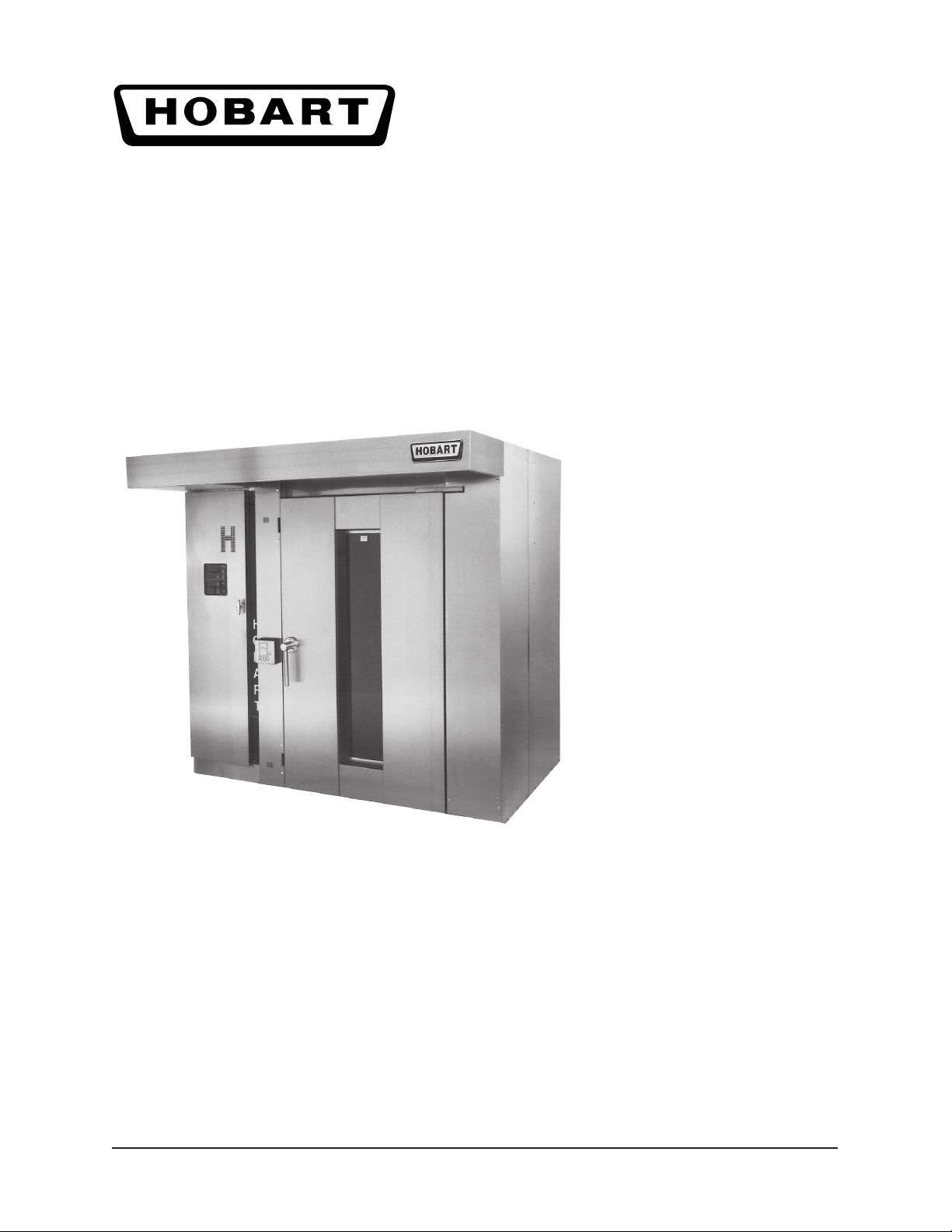
MODEL DRO2G
RACK OVEN
A product of HOBART CORPORATION 701 S. RIDGE AVENUE TROY, OHIO 45374-0001
FORM 19217 Rev. A (November 2001)
Page 2
MODEL DRO2G RACK OVEN REPLACEMENT PARTS
1
2
3
16
20
21
18
19
17
14-15
5
4
6
9
7
13
12
8
10-11
F-19217 Rev. A (November 2001)
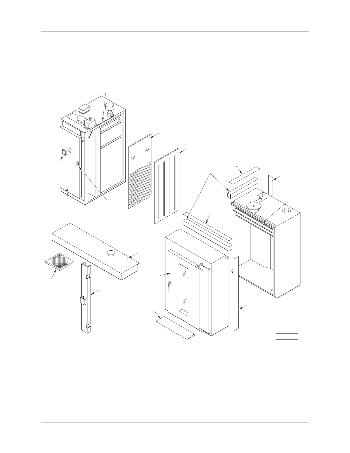
ROTARY OVEN ASSEMBLY
- 2 -
PL-55906
© HOBART CORPORATION
Page 3

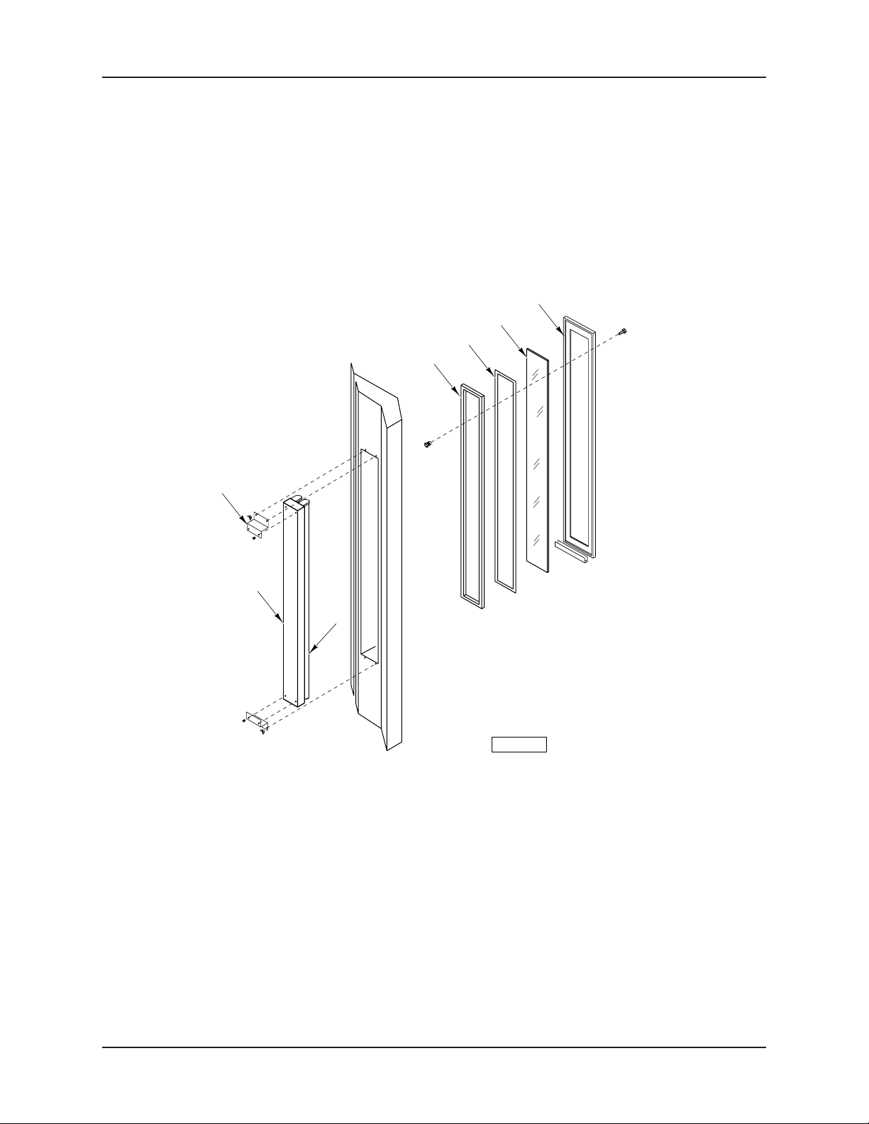
MODEL DRO2G RACK OVEN REPLACEMENT PARTS
ROTARY OVEN ASSEMBLY
ILLUS. PART NO. NAME OF PART AM T.
PL-55906
1 00-630172-00031 Rod – Damper ............................................................................................................................. 1
2 00-630130-00002 Plate – Return Air Perforated .....................................................................................................1
3 00-630131 Adjustable Slotted Plate Assy. ................................................................................................... 1
4 00-630130-00038 Strip – Insulation ......................................................................................................................... 2
5 00-630130-00007 Strip (Right and Left Section)..................................................................................................... 1
6 00-630130-00010 Strip – Vertical (Back) ................................................................................................................ 1
7 00-630130-00006 Strip (Back and Front Section)...................................................................................................1
8 00-630130-00011 Strip – Vertical (Right) ................................................................................................................ 1
9 00-837002-00001 Gasket – Fiberglass ................................................................................................................. AR
10 00-630171-00013 Ramp Assy. ................................................................................................................................ 1
11 00-630161-00002 Mach. Screw 8-32 x 1/2 Slotted Hd. ...........................................................................................4
12 00-630113 Door Assy................................................................................................................................... 1
13 00-630197 Hood Assy. .................................................................................................................................1
14 00-630130-00009 Panel – Vertical Filler (Left) ........................................................................................................ 1
15 00-630174-00062 Panel – Vertical Filler (Right) ......................................................................................................1
16 00-630152-00007 Filter ............................................................................................................................................3
17 00-630151-00023 Handle – Burner Door ................................................................................................................ 1
18 00-630108 Burner Door Assy. (With Sysmac Control) ................................................................................ 1
19 00-630193 Burner Door Assy. (With Electronic Control) .............................................................................1
20 00-630142-00088 Electronic Control Box Assy. ..................................................................................................... 1
21 00-630143-00003 Control-Oven Programmable ...................................................................................................... 1
00-630161-00011 Plug – Button .............................................................................................................................. 1
00-630151-00057 Key – Allen (For Electrical Box) ................................................................................................. 1
00-791219 Facia – Top .................................................................................................................................1
00-630161-00011 Plug – Button .............................................................................................................................. 1
00-630161-00001 Wedge – Oven ..........................................................................................................................36
01-009485 Socket – Light (Rear Glass Unit) ............................................................................................... 1
- 3 -
F-19217 Rev. A (November 2001)
Page 4
MODEL DRO2G RACK OVEN REPLACEMENT PARTS
16
1
2
3
4
15
14
13
12
11
10
9
5
6
7
8
PL-55912
F-19217 Rev. A (November 2001)
FILLER PIECES ASSEMBLY
- 4 -
Page 5

MODEL DRO2G RACK OVEN REPLACEMENT PARTS
FILLER PIECES ASSEMBLY
ILLUS. PART NO. NAME OF PART AM T.
PL-55912
1 00-630101-00001 Side – Left Exterior ....................................................................................................................1
2 00-630191-00002 Back – Left Exterior ................................................................................................................... 1
3 00-630125-00002 Clad – External Back .................................................................................................................. 1
4 00-630125-00001 Clad – External Right Corner ......................................................................................................1
5 00-630111-00001 Clad – External ...........................................................................................................................1
6 00-630130-00008 Panel – Vertical Filler (Right) ......................................................................................................1
7 00-630161-00002 Mach. Screw 8-32 x 1/2 Slotted Hd. ...........................................................................................4
8 00-630161-00011 Button – Plug 1/2 (SST) ................................................................................................................3
9 00-630151-00054 Tape – Double Adhesive (1/2 x 0.050 In. Thick) .......................................................................... 1
10 00-630130-00028 Holder – Gloves.......................................................................................................................... 1
11 00-630171-00053 Mach. Screw 8-32 x 4 ............................................................................................................... 2
12 00-630191-00003 Panel – Burner Vent ...................................................................................................................1
13 00-630151-00024 Latch – Adjustable (For Burner Door) ....................................................................................... 1
14 00-630151-00023 Handle – Burner Door ................................................................................................................ 1
15 00-630171-00039 Door – Burner Section ............................................................................................................... 1
16 - Screw 5/16-18 x 3/4 Hex Hd. ....................................................................................................... 6
00-630152-00023 Label – Hood ..............................................................................................................................1
- 5 -
F-19217 Rev. A (November 2001)
Page 6
MODEL DRO2G RACK OVEN REPLACEMENT PARTS
13
53
52
51
44 THRU 50
1-2-3
12
11
10
4
5
6
7
8
9
19
14-15
16
17
18
20
21
43
42
41
25
39
34
27
26
33
32
30-31
29
28
40
38
37
35
36
DOOR ASSEMBLY (OVEN)
22
2324
PL-55911
F-19217 Rev. A (November 2001)
- 6 -
Page 7

MODEL DRO2G RACK OVEN REPLACEMENT PARTS
ASSEMBLY (OVEN)
ILLUS. PART NO. NAME OF PART AM T.
PL-55911
1 00-630113-00005 Clad – Door (Back) .....................................................................................................................1
2 00-630151-00004 Gasket – Silicone (76 In.) (Sides) ...............................................................................................
3 00-630151-00005 Gasket – Silicone (42
4 00-630151-00048 Silicone – Heat Resistant ......................................................................................................... AR
5 00-630151-00019 Glass – Heat Reflective 12 x 57
6 00-630151-00029 Rock Wool 2 Ft. x 4 Ft. x 11/2 In. .................................................................................................2
7 00-630151-00043 Gasket – Fiberglass 1 In. x 1/16 In. (Comes in 100 Ft. Roll) ...................................................... AR
8 00-630151-00053 Tape – Double Adhesive 1 In. (Comes in 100 Ft. Roll) ............................................................. AR
9 00-630171-00007 Outside Clad Assy. ..................................................................................................................... 1
10 00-630130-00082 Bracket – Switch .......................................................................................................................1
11 00-630161-00009 Washer – Flat 5/16 ........................................................................................................................ 1
12 00-630161-00048 Lockwasher 3/8 ........................................................................................................................... 1
13 00-630161-00030 Bolt
5
/16-16 x 3/4 Hex Hd. (SST) ...................................................................................................1
14 00-630142-00090 Switch – Micro ........................................................................................................................... 1
15 00-630142-00091 Case – Switch............................................................................................................................ 1
16 00-630171-00041 Top Hinge & Shaft Assy. ............................................................................................................1
17 00-630113-00011 Bushing – Door ........................................................................................................................... 1
18 00-630213-00001 Bracket – Top Hinge (On Door Jamb) ........................................................................................ 1
19 00-630113-00013 Bracket – Door Jamb (Bottom Hinge) ........................................................................................ 1
20 00-630113-00011 Bushing – Door ........................................................................................................................... 1
21 00-630171-00010 Bottom Hinge & Shaft Assy. ....................................................................................................... 1
22 00-630161-00011 Button – Plug
23 00-630171-00011 Vertical Moulding & Retaining Strip Assy. .................................................................................. 2
24 00-630113-00022 Molding – Horizontal ................................................................................................................... 2
25 00-630113-00040 Spacer – Inside Handle .............................................................................................................. 1
26 00-630113-00037 Plate – Mounting Outside Handle ............................................................................................... 1
27 00-630161-00009 Screw 8-32 Oval Hd. ................................................................................................................. 4
28 00-630113-00035 Base – Handle Outside (Previous Construction) ...................................................................... 1
29 00-630152-00062 Shaft – Handle (Current Construction) ...................................................................................... 1
30 00-630113-00036 Shaft – Handle Outside (Previous Construction) ......................................................................1
31 00-630152-00061 Handle – Outside (Current Construction) ..................................................................................1
32 00-630161-00080 Screw – Handle Outside ............................................................................................................ 1
33 00-630113-00038 Collar – Handle Outside .............................................................................................................. 1
34 00-630113-00039 Shaft – Handle............................................................................................................................ 1
35 00-630113-00034 Plate – Mounting Inside Handle ..................................................................................................1
36 00-630161-00002 Mach. Screw 8-32 x 1/2 .............................................................................................................. 2
37 00-630113-00033 Shaft – Inside Handle ................................................................................................................. 1
38 00-630113-00032 Base – Inside Handle .................................................................................................................1
39 00-630113-00026 Strip – Retaining.......................................................................................................................... 6
40 00-630113-00025 Strip – Spacing Masonite 2 x 731/4 .............................................................................................. 4
41 00-630151-00022 Mechanism – Handle (Main Door) ..............................................................................................1
42 00-630113-00009 Panel – Mobile Locking Device ................................................................................................... 1
43 00-630113-00010 Cover – Locking Device .............................................................................................................1
44 00-630440-00001 Bracket – Switch .......................................................................................................................1
45 00-630151-00090 Bearing – Roller ..........................................................................................................................1
46 00-630161-00080 Cap Screw 5/16-18 x 1 Hex Hd. .................................................................................................. 1
47 00-837018-00044 Plate ............................................................................................................................................1
48 SC-041-11 Screw 5/16-18 x 3/4 Hex Hd. (SST) .............................................................................................. 2
49 WS-017-08 Washer (SST) ............................................................................................................................2
50 NS-048-56 Lock Nut 5/16-18 ...........................................................................................................................1
51 00-630113-00017 Angle – Retainer Door Wiper .....................................................................................................1
52 00-630113-00019 Wiper – Door (Silicone) ..............................................................................................................1
53 00-630113-00018 Retainer – Door Wiper ................................................................................................................ 1
00-630113-0000G Door – Assy. (Left Hand Open) .................................................................................................1
00-630113-0000D Door – Assy. (Right Hand Open) ............................................................................................... 1
00-630130-00024 Label – Warning ......................................................................................................................... 1
5
/8 In.) ........................................................................................................1
1
/4 x 3/16 ..................................................................................... 1
1
/2 (SST) ................................................................................................................4
- 7 -
F-19217 Rev. A (November 2001)
Page 8
MODEL DRO2G RACK OVEN REPLACEMENT PARTS
1
2
3
4
5
6
7
PL-51063
F-19217 Rev. A (November 2001)
LIGHT FIXTURE ASSEMBLY
- 8 -
Page 9

MODEL DRO2G RACK OVEN REPLACEMENT PARTS
LIGHT FIXTURE ASSEMBLY
ILLUS. PART NO. NAME OF PART AM T.
PL-51063
1 00-630114-00001 Retainer – Glass ........................................................................................................................ 2
2 00-630151-00018 Glass – Heat Reflective 6 In. Wide x 50 In. Lg. x 3/16 Thk. ......................................................... 1
3 00-630151-00053 Tape – Double Adhesive 1 In. (Comes in 100 Ft. Roll) ............................................................. AR
4 00-630151-00043 Gasket – Fiberglass 1 In. x 1/16 In. (Comes in 100 Ft. Roll) ...................................................... AR
5 00-630114-00002 Bracket – Fluorescent ................................................................................................................ 2
6 00-630141-00028 Fixture – Fluorescent (Incls. Ballast) .........................................................................................1
7 00-630141-00029 Tube – Fluorescent Sylvania 48 In. (F40CW) ........................................................................... 2
- 9 -
F-19217 Rev. A (November 2001)
Page 10

MODEL DRO2G RACK OVEN REPLACEMENT PARTS
1
2
3
4
10 THRU 14
9
5
6
7
8
PL-55907
F-19217 Rev. A (November 2001)
RACK ROTATING DRIVE ASSEMBLY
- 10 -
Page 11

MODEL DRO2G RACK OVEN REPLACEMENT PARTS
RACK ROTATING DRIVE ASSEMBLY
ILLUS. PART NO. NAME OF PART AM T.
PL-55907
1 00-630151-00026 Pulley (21/2 In.) .............................................................................................................................1
2 00-630161-00033 Nut 3/8 (SST) ................................................................................................................................1
3 00-630161-00034 Washer .......................................................................................................................................1
4 00-630171-00005 Belt Tightener Assy. ................................................................................................................... 1
5 00-630151-00003 Spring – Torsion.......................................................................................................................... 1
6 00-630106-00002 Bushing ......................................................................................................................................1
7 00-630171-00006 Support – Belt Tightener ............................................................................................................ 1
8 00-630161-00069 Bolt 3/8-16 x 31/2 (SST) ................................................................................................................ 1
9 00-630106-00001 Bracket – Motor Rotating Drive ..................................................................................................1
10 00-630152-00058 Reducer ......................................................................................................................................1
11 00-630106-00008 Bracket – Motor ..........................................................................................................................2
12 00-630161-00014 Bolt 3/8-16 x 3 Hex Hd. ................................................................................................................ 8
13 00-630161-00048 Washer .......................................................................................................................................8
14 00-630106-00009 Support – Belt Tension ............................................................................................................... 1
- 11 -
F-19217 Rev. A (November 2001)
Page 12

MODEL DRO2G RACK OVEN REPLACEMENT PARTS
1
37
28
27
13
14
15
16
21
26
17 THRU 20
22
23
24
25
PL-55910
2
3
4
6
5
36
35
34
7
8
9
11
12
10
29
30
31
32
33
F-19217 Rev. A (November 2001)
LIFTING DEVICE ASSEMBLY
- 12 -
Page 13

MODEL DRO2G RACK OVEN REPLACEMENT PARTS
LIFTING DEVICE ASSEMBLY
ILLUS. PART NO. NAME OF PART AM T.
PL-55910
1 00-630151-00001 Belt .............................................................................................................................................. 1
2 00-630161-00006 Lock Nut 1/2-20 ............................................................................................................................1
3 00-630151-00055 Joint – Ball Female 1/2 .................................................................................................................. 1
4 00-630161-00010 Washer .......................................................................................................................................2
5 00-630161-00004 Bolt Hex
6 00-630152-00009 Rod .............................................................................................................................................1
7 00-630152-00040 Coupling – Rod ........................................................................................................................... 1
8 00-630152-00041 Connector – Rod ........................................................................................................................ 1
9 00-630151-00055 Joint – Ball Female
10 00-630151-00012 Ring – Snap External 25/32 ............................................................................................................1
11 00-630121-00002 Sleeve – Lifting Device Spacing ................................................................................................1
12 00-630151-00015 Bearing – Thrust ........................................................................................................................ 1
13 00-630151-00010 Bearing – Ball ............................................................................................................................. 1
14 00-630151-00012 Ring – Snap External 25/32 ............................................................................................................1
15 00-630153-00051 Bushing ......................................................................................................................................2
16 00-630151-00014 Key 3/8 x 3/8 x 2 ............................................................................................................................1
17 00-630123 Device – Lifting Assy. (Style C) .................................................................................................1
18 00-630171-00056 Device – Lifting Assy. (Style C) (17/8 In. Longer) .......................................................................1
19 00-630128-00001 Device – Lifting Assy. (Style A) .................................................................................................1
20 00-630129 Device – Lifting Assy. (Style B) .................................................................................................1
21 00-630161-00047 Mach. Screw 1/4-20 x 1 Flat Hd. (SST) ......................................................................................2
22 00-630123-00004 Device – Locking ........................................................................................................................ 2
23 00-630123-00005 Bushing – Locking Device .........................................................................................................2
24 00-630161-00008 Washer .......................................................................................................................................2
25 00-630161-00036 Lock Nut 1/4-20 ............................................................................................................................2
26 00-630121-00006 Bracket – Limit Switch ............................................................................................................... 1
27 00-630141-00016 Switch – Limit .............................................................................................................................1
28 00-630122 Pivot Bracket Assy. .................................................................................................................... 1
29 00-630122-00004 Bushing ......................................................................................................................................1
30 00-630151-00010 Bearing – Ball ............................................................................................................................. 1
31 00-630151-00013 Ring – Snap External 13/8 ............................................................................................................1
32 00-630121-00007 Bracket – Carriage Lift ...............................................................................................................1
33 00-630124-00003 Shim ........................................................................................................................................... 10
34 00-630151-00016 Pulley 14 In. Dia. ......................................................................................................................... 1
35 00-630121-00008 Bracket – Limit Switch Pulley .....................................................................................................1
36 00-630121-00001 Washer – Lifting Device............................................................................................................. 1
37 00-630161-00013 Lock Nut 1-14 .............................................................................................................................1
1
/2 x 20 x 21/4 ................................................................................................................. 1
1
/2 .................................................................................................................. 1
- 13 -
F-19217 Rev. A (November 2001)
Page 14

MODEL DRO2G RACK OVEN REPLACEMENT PARTS
1
2
3
4
7
5
6
PL-51029
F-19217 Rev. A (November 2001)
LIFTING DEVICE ASSEMBLY
- 14 -
Page 15

MODEL DRO2G RACK OVEN REPLACEMENT PARTS
BLOWER AND DRIVE ASSEMBLY
ILLUS. PART NO. NAME OF PART AM T.
PL-51029
1 00-630141-00031 Motor – Fan 3 Hp. .......................................................................................................................1
2 00-630105-00001 Support – Fan Motor .................................................................................................................. 1
3 00-630171-00004 Plate & Spring Assy. ................................................................................................................... 1
4 00-630151-00020 Wheel (Clockwise) ..................................................................................................................... 1
5 00-630151-00021 Ring – Inlet .................................................................................................................................. 1
6 00-630105-00003 Bushing – Fan Oilite ................................................................................................................... 1
7 00-630151-00017 Pulley – 6 In. (11/8 Shaft, 1/4 Keyway) ........................................................................................ 1
- 15 -
F-19217 Rev. A (November 2001)
Page 16

MODEL DRO2G RACK OVEN REPLACEMENT PARTS
41
40
39
38
37
1
29
30
31
32
36
35
34
33
9
10
11
12
13
14
2
3
4-5
6
7
8
15
16
17
F-19217 Rev. A (November 2001)
27-28
25
26
24
400 GAS BURNER
HSG (WAYNE)
- 16 -
23
22
18
19
20
21
PL-55909
Page 17

MODEL DRO2G RACK OVEN REPLACEMENT PARTS
400 GAS BURNER
HSG (WAYNE)
ILLUS. PART NO. NAME OF PART AM T.
PL-55909
1 00-688287 Valve – Gas 7000DERHC ...........................................................................................................1
2 00-688282 Bushing – Strain Relief/Ignition Wire .......................................................................................... 1
3 00-688281 Bushing – Strain Relief/Sensor Wire ......................................................................................... 1
4 00-688279 Wire – Ignition 8 In. .....................................................................................................................1
5 00-688278 Wire – Sensor 11 In.................................................................................................................... 1
6 00-688277 Support – Electrode Bracket (Incls. Items 7, 34 & Set Screws)............................................... 2
7 00-688274 Bushing – Insulator .................................................................................................................... 2
8 00-688273 Sensor Probe Assy. ................................................................................................................... 1
9 00-688270 Box – Junction............................................................................................................................ 1
10 00-688263 Pointer – Damper Indicator .........................................................................................................1
11 00-688267 Arm – Adjustment Off-Cycle Damper ........................................................................................ 1
12 00-688269 Bracket – Off-Cycle Damper Mounting ......................................................................................1
13 00-688268 Plate – Off-Cycle Damper .......................................................................................................... 1
14 00-688250 Housing – Burner ....................................................................................................................... 1
15 00-688262 Control – Primary Safety Without 30 Sec. Prepurge (S89E-1033) (See TSB-806) .................. 1
16 00-616973 Controller (S89F) ........................................................................................................................1
17 00-688261 Relay – Motor ............................................................................................................................. 1
18 00-688260 Transformer (24 V.) ................................................................................................................... 1
19 00-688266 Strip – Thermostat Terminal ........................................................................................................1
20 00-688258 Box – Control .............................................................................................................................. 1
21 00-688259 Timer With Resistor Wire Assy. (See TSB-806) ........................................................................ 1
22 00-688265 Switch Mounting Plate Slot Cover Assy. ................................................................................... 1
23 00-688265 Switch – Air Proving ..................................................................................................................1
24 00-688263 Pointer – Damper Indicator .........................................................................................................1
25 00-688257 Damper – Combustion Air Inlet ................................................................................................... 1
26 00-688251 Tube – Air (61/4 In.) ..................................................................................................................... 1
27 00-688253 Gasket – Flange ......................................................................................................................... 1
28 00-688252 Adjustable Flange Assy. ............................................................................................................ 1
29 00-688256 Motor – Split Phase 1/7 or 1/8 Hp., 3450 RPM, 115 V./60 .............................................................. 1
30 00-688254 Wheel – Blower 51/2 In. O.D. ...................................................................................................... 1
31 00-688255 Plate – Side ................................................................................................................................. 1
32 00-688271 Transformer – Ignition (7500 V.)................................................................................................ 1
33 00-688272 Electrode Assy. ..........................................................................................................................1
34 00-688275 Manifold – Chamber 61/4 In. ........................................................................................................ 1
35 00-688276 Clip – Electrode Bracket .............................................................................................................1
36 00-688280 Plate – Top/Housing Cover ......................................................................................................... 1
37 00-688283 Housing – Orifice ....................................................................................................................... 1
38 00-688289 Orifice (0.468 In. Drill) ................................................................................................................ 1
39 00-688284 Spring – Orifice...........................................................................................................................1
40 00-688285 Gasket – Orifice ......................................................................................................................... 1
41 00-688286 Cap – Orifice .............................................................................................................................. 1
00-618897 Regulator – Pressure Valve ....................................................................................................... 1
00-663657 Burner – Gas (Complete) ...........................................................................................................1
00-630143-00023 Kit – Propane .............................................................................................................................. 1
00-687940 Kit – Pressure Switch ................................................................................................................ 1
- 17 -
F-19217 Rev. A (November 2001)
Page 18

MODEL DRO2G RACK OVEN REPLACEMENT PARTS
18
17
16
15
1
2
3
4
5
13
12
10
11
14
6
PL-51569
9
8
7
F-19217 Rev. A (November 2001)
HEAT EXCHANGER
(GAS)
- 18 -
Page 19

MODEL DRO2G RACK OVEN REPLACEMENT PARTS
HEAT EXCHANGER
(GAS)
ILLUS. PART NO. NAME OF PART AM T.
PL-51569
1 00-630161-00030 Bolt 5/16-18 x 3/4 Hex Hd. .............................................................................................................. 4
2 00-630161-00048 Lockwasher ............................................................................................................................... 4
3 00-630161-00009 Washer .......................................................................................................................................4
4 00-630151-00043 Gasket – Fiberglass 1 In. x 1/16 In. (Comes in 100 Ft. Roll) ...................................................... AR
5 00-630151-00053 Tape – Double Adhesive 1 In. (Comes in 100 Ft. Roll) ............................................................. AR
6 00-630196 Heat Exchanger Assy. ............................................................................................................... 1
7 00-630171-00042 Plate Assy................................................................................................................................... 1
8 00-630161-00034 Washer .......................................................................................................................................4
9 00-630161-00033 Nut 3/8 Hex ...................................................................................................................................4
10 00-630161-00030 Bolt 5/16-18 x 3/4 Hex Hd. .............................................................................................................. 1
11 00-630102-00022 Port – Observation .....................................................................................................................1
12 00-630196-00021 Panel – Front Box Protection ..................................................................................................... 1
13 00-630161-00046 Mach. Screw 8-32 x 2 Slotted Hd. ............................................................................................2
14 00-630161-00032 Tric Nut 8-32 ............................................................................................................................... 2
15 00-630161-00030 Bolt 5/16-18 x 3/4 Hex Hd. ............................................................................................................. 12
16 00-630171-00043 Heat Exchanger Cover Assy. .................................................................................................... 1
17 00-630151-00043 Gasket – Fiberglass 1 In. x 1/16 In. (Comes in 100 Ft. Roll) ...................................................... AR
18 00-630151-00053 Tape – Double Adhesive 1 In. (Comes in 100 Ft. Roll) ............................................................. AR
00-616595 Inducer – Draft (0-15 Ft.) ........................................................................................................... 1
00-630143-00020 Inducer – Draft (16-100 Ft.) .......................................................................................................1
00-616597 Damper – Barometric ................................................................................................................. 1
00-684320 Switch – Pressure Safety .........................................................................................................1
- 19 -
F-19217 Rev. A (November 2001)
Page 20

MODEL DRO2G RACK OVEN REPLACEMENT PARTS
15
14
1
13
12
11
2
3
10
9
8
7
4
6
F-19217 Rev. A (November 2001)
5
PL-51027
STEAM GENERATOR ASSEMBLY
- 20 -
Page 21

MODEL DRO2G RACK OVEN REPLACEMENT PARTS
STEAM GENERATOR ASSEMBLY
ILLUS. PART NO. NAME OF PART AMT.
PL-51027
1 00-630109-00021 Cover – Heat Accumulator ......................................................................................................... 1
2 00-630171-00003 Steam Pipe Assy. (37 In. Lg.) ..................................................................................................... 1
3 00-630151-00037 Cap 3/8 NPT Female (SST) ...........................................................................................................1
4 00-630151-00039 Plug – Sq. Hd. 1 NPT Male (SST) ............................................................................................... 1
5 00-630161-00061 Coupling – Female 1 In. NPT ....................................................................................................... 1
6 00-630103-00007 Baffle – Steam Generator ......................................................................................................... 16
7 00-630103-00002 Accumulator – Heat 3 Rows .................................................................................................... 32
8 00-630103-00001 Accumulator – Heat 2 Rows .................................................................................................... 32
9 00-630161-00061 Coupling – Female 1 In. NPT ....................................................................................................... 1
10 00-630141-00034 Valve – Solenoid ........................................................................................................................ 1
11 00-630151-00035 Bushing – Hex 3/8 NPT Internal, 1/2 NPT External (SST) ..............................................................1
12 00-630151-00034 Nipple 3/8 NPT (SST) ....................................................................................................................1
13 00-630151-00033 Union 3/8 NPT Female (SST) ........................................................................................................ 1
14 00-630151-00032 Elbow 3/8 NPT Male-Female (SST) .............................................................................................. 1
15 00-630103-00003 Retainer – Steam Pipe ................................................................................................................ 1
01-100V17-00330 Regulator – Pressure Water (Panera Bread) ............................................................................ 1
01-100V17-00089 Valve – Ball (Bronze) (Panera Bread) ....................................................................................... 1
01-100V17-00204 Gauge – Pressure (Panera Bread)............................................................................................1
01-100V17-00275 Strainer (Brass) (Panera Bread) ............................................................................................... 1
01-100V17-00274 Valve – Solenoid 1/2 (Panera Bread) .......................................................................................... 1
- 21 -
F-19217 Rev. A (November 2001)
Page 22

MODEL DRO2G RACK OVEN REPLACEMENT PARTS
21
19-20
1
2
3
18
6
4-5
7-8
17
9-10
H
16
O
15
11-12
13
14
CONTROL PANEL
B
A
R
T
PL-55908
ELECTRONIC CONTROLMECHANICAL CONTROL
F-19217 Rev. A (November 2001)
- 22 -
Page 23

MODEL DRO2G RACK OVEN REPLACEMENT PARTS
CONTROL PANEL
ILLUS. PART NO. NAME OF PART AM T.
PL-55908
1 00-630171-00016 Panel – Control Box ....................................................................................................................1
2 00-630151-00052 Bushing – Snap ..........................................................................................................................1
3 00-630171-00040 Panel – Hobart (Use W/Electronic Control) ................................................................................ 1
4 00-630171-00017 Damper Activating Stem Assy. ...................................................................................................1
5 00-630109-00045 Plate – Adjustable (For Damper Control Stem) .......................................................................... 1
6 00-630161-00015 Ball – Plastic (With Brass Insert 3/8-16) (15/8 O.D.) ..................................................................... 1
7 00-630141-00001 Switch – High Limit Control ........................................................................................................ 1
8 00-630141-00003 Buzzer – Sonalert ...................................................................................................................... 1
9 00-630141-00005 Timer – SAIA (KKH 20200 B5J2 U00) (Min.) .............................................................................. 1
10 00-630153-00039 Knob – Timer .............................................................................................................................. 2
11 00-630141-00037 Button – Jog ............................................................................................................................... 1
12 00-630141-00067 Clock – Contact Jog Button ........................................................................................................1
13 00-630171-00015 Panel – Center ............................................................................................................................1
14 00-630171-00014 Panel – Lower ............................................................................................................................ 1
15 00-630141-00007 Selector – Main Power Switch .................................................................................................. 1
16 00-630141-00006 Timer – SAIA (KKH 20200 E3J1U00) (Sec.) ..............................................................................1
17 00-630141-00002 Thermostat – Electronic ............................................................................................................. 1
18 00-630161-00015 Ball – Plastic (With Brass Insert 3/8-16) (15/8 O.D.) ..................................................................... 1
19 00-630171-00017 Damper Activating Stem Assy. ...................................................................................................1
20 00-630109-00045 Plate – Adjustable (For Damper Control Stem) .......................................................................... 1
21 00-630151-00052 Bushing – Snap ..........................................................................................................................1
- 23 -
F-19217 Rev. A (November 2001)
Page 24

MODEL DRO2G RACK OVEN REPLACEMENT PARTS
1 - 2
10
12
13
14
15
16
17
18
19
20
21
22
23
24
CONTROL BOX
5432
6
3CR
3
4
5
7
7
8
9
13
5
A2
A2
3
1 CR
1
A1
13 14
5
A2
A2
3 CON
3
1
A1
13 14
5
A2
A2
2 CON
3
1
A1
13 14
5
A2
A2
1 CON
3
1
A1
1
7CB
1
6CB
1
5CB
3
4
3TR
5
6
B1A1B2 A2
4TR
15 16 18
23
13 14
56
M3
34
12
56
M2
34
12
23 13 14 24
56
M1
34
12
5643
1
11
10
31
30
4CR
2
8
2
7
1
PVC BOX 8" X 8" X 4"
5643
6 TR
8
7
2
1
33
32
6
8
CONTROL PANEL
9
11
14
6
4
2
6
4
2
6
4
2
6
4
2
2
1
8
7
24
61 62
53
54
2
2
2
29
28
5
4
3
2
1
1
2
3
1
2
3
1
5
6
2
1 TEC
3
4
1 SW
+-
1 TR
2 TR
GND
10
9
8
7
6
4
5
6
4
5
6
1H. - T.
3
7
8
4
34
35
36
38
39
40
41
42
37
41
GND
2 TAS
42
CONTROL PANEL INSIDE
25
26
27
F-19217 Rev. A (November 2001)
PL-51571
WITH MECHANICAL CONTROL
GAS CONTROL
(STANDARD)
- 24 -
Page 25

MODEL DRO2G RACK OVEN REPLACEMENT PARTS
GAS CONTROL
(STANDARD)
ILLUS. PART NO. NAME OF PART AM T.
PL-51571
1 00-630141-00042 Relay 3 Pole ................................................................................................................................ 1
2 00-630141-00043 Socket – Relay (11 Pins) ............................................................................................................ 1
3 00-630141-00072 End – Stop .................................................................................................................................. 1
4 00-630141-00070 End – Section ............................................................................................................................. 1
5 00-630141-00071 Block – Terminal ..........................................................................................................................3
6 00-630141-00070 End – Section ............................................................................................................................. 1
7 00-630141-00069 Connector ................................................................................................................................... 4
8 00-630141-00076 Bar – Jumper (10 Pole) .............................................................................................................. 2
9 00-630141-00070 End – Section ............................................................................................................................. 1
10 00-630141-00069 Connector ................................................................................................................................... 5
11 00-630141-00070 End – Section ............................................................................................................................. 1
12 00-630141-00069 Connector ................................................................................................................................... 1
13 00-630141-00012 Contactor (12 Amp.)................................................................................................................... 3
14 00-630141-00013 Contactor (9 Amp.)..................................................................................................................... 1
15 00-630141-00015 Breaker (10 Amp.) ...................................................................................................................... 1
16 00-630141-00014 Breaker (6 Amp.) ........................................................................................................................ 2
17 00-630141-00017 Timer – Omron (H3G-8ACI20-30S) ............................................................................................1
18 00-630141-00019 Timer (30 Min.)............................................................................................................................ 1
19 00-630141-00069 Connector ................................................................................................................................... 1
20 00-630141-00070 End – Section ............................................................................................................................. 1
21 00-630141-00008 Starter – Manual (1.6 Amp.) .......................................................................................................1
22 00-630141-00009 Starter – Manual ......................................................................................................................... 1
23 00-630141-00011 Contactor – Aux. ........................................................................................................................1
24 00-630141-00010 Starter – Manual (10 Amp.) ........................................................................................................1
25 00-630141-00069 Connector ................................................................................................................................... 5
26 00-630141-00070 End – Section ............................................................................................................................. 1
27 00-630141-00072 End – Stop ..................................................................................................................................1
28 00-630141-00018 Socket – Relay (8 Pins) .............................................................................................................. 1
29 00-630141-00040 Contact – Aux. ............................................................................................................................ 1
30 00-630141-00021 Bar – Grounding ......................................................................................................................... 1
31 00-630141-00020 Relay........................................................................................................................................... 1
32 00-630141-00039 Timer (0-10 Sec.) ....................................................................................................................... 1
33 00-630141-00018 Socket – Relay (8 Pins) .............................................................................................................. 1
34 00-630141-00003 Buzzer – Sonalert ...................................................................................................................... 1
35 00-630184-00036 Buzzer (W/Ribbon Cable) .......................................................................................................... 1
36 00-630141-00002 Thermostat – Electronic ............................................................................................................. 1
37 00-630141-00001 Switch – High Limit Control ........................................................................................................ 1
38 00-630141-00005 Timer – SAIA (KKH 20200 B5J2 U00) (Min.) .............................................................................. 1
39 00-630141-00006 Timer – SAIA (KKH E3J1U00) (Sec.) ........................................................................................ 1
40 00-630141-00037 Button – Jog ............................................................................................................................... 1
41 00-630141-00067 Clock – Contact Jog Button ........................................................................................................1
42 00-630141-00007 Selector – Main Power Switch .................................................................................................. 1
- 25 -
F-19217 Rev. A (November 2001)
Page 26

MODEL DRO2G RACK OVEN REPLACEMENT PARTS
UP
DOWN
UP
DOWN
STACK FAN
PROVER
2
3
4
5
9
11
1
STACK FAN
MOTOR
2 TAS
20
13 14
5
3
1
13 14
5
3
1
13 14
5
3
1
13 14
5
3
1
32
4
5
6
1
1
1
56
34
12
56
34
12
A2
4 CON
A1
A2
3 CON
A1
A2
2 CON
A1
A2
1 CON
A1
4 CR
3CB
2CB
1CB
M2
M1
80
6
A2
4
2
6
A2
4
2
6
A2
4
2
6
A2
4
2
1
8
7
2
2
2
6
7
10
12
13
14
ROTOR
SWITCH
15
16
17
18
ROTOR
MOTOR
8
FAN
MOTOR
BURNER
VALVE
DOOR
SWITCH
CONTROL BOX
ELECTRONIC CIRCUIT
F-19217 Rev. A (November 2001)
19
PL-51572
WITH ELECTRONIC CONTROL
GAS CONTROL
(WITH ELECTRONIC CONTROL)
- 26 -
Page 27

MODEL DRO2G RACK OVEN REPLACEMENT PARTS
GAS CONTROL
(WITH ELECTRONIC CONTROL)
ILLUS. PART NO. NAME OF PART AM T.
PL-51572
1 00-630142-00097 Board – Relay (For Electronic Control) ......................................................................................1
2 00-630141-00001 Switch – High Limit Control ........................................................................................................ 1
3 00-630141-00072 End – Stop .................................................................................................................................. 1
4 00-630141-00070 End – Section ............................................................................................................................. 1
5 00-630141-00071 Block – Terminal ..........................................................................................................................3
6 00-630141-00070 End – Section ............................................................................................................................. 1
7 00-630141-00076 Bar – Jumper (10 Pole) .............................................................................................................. 1
8 00-630141-00021 Bar – Grounding ......................................................................................................................... 1
9 00-630141-00069 Connector .................................................................................................................................. 18
10 00-630141-00070 End – Section ............................................................................................................................. 2
11 00-630141-00012 Contactor (12 Amp.)................................................................................................................... 3
12 00-630141-00013 Contactor (9 Amp.)..................................................................................................................... 1
13 00-630141-00020 Relay........................................................................................................................................... 1
14 00-630141-00018 Socket – Relay (8 Pins) .............................................................................................................. 1
15 00-63011-00015 Breaker (10 Amp.) ...................................................................................................................... 1
16 00-630141-00014 Breaker (8 Amp.) ........................................................................................................................ 2
17 00-630141-00008 Starter – Manual (1.6 Amp.) .......................................................................................................1
18 00-630141-00010 Starter – Manual (10 Amp.) ........................................................................................................1
19 00-630142-00085 Transformer (120/12-12) ........................................................................................................... 1
00-630142-00098 Cable – Flat (For Electronic Control) (Male) ...............................................................................1
00-636171-00094 Control Box Assy. ...................................................................................................................... 1
01-009439 Varistor (130 V.) ........................................................................................................................1
00-630141-00074 Rod – Nylon ................................................................................................................................ 2
00-630143-00049 Relay ...........................................................................................................................................1
00-630143-00015 Probe – Relay (176 In.) .............................................................................................................. 1
00-630142-00089 Cable – Flat (Female) ................................................................................................................. 1
00-630142-00089 Cable – Flat (Female) ................................................................................................................. 1
00-630143-00003 Control – Oven Programmable ................................................................................................... 1
- 27 -
F-19217 Rev. A (November 2001)
Page 28

MODEL DRO2G RACK OVEN REPLACEMENT PARTS
FORM 19217 Rev. A NOVEMBER 2001 PRINTED IN U.S.A.
 Loading...