

Page 1
\HOBART]
FOOD
EQUIPMENT
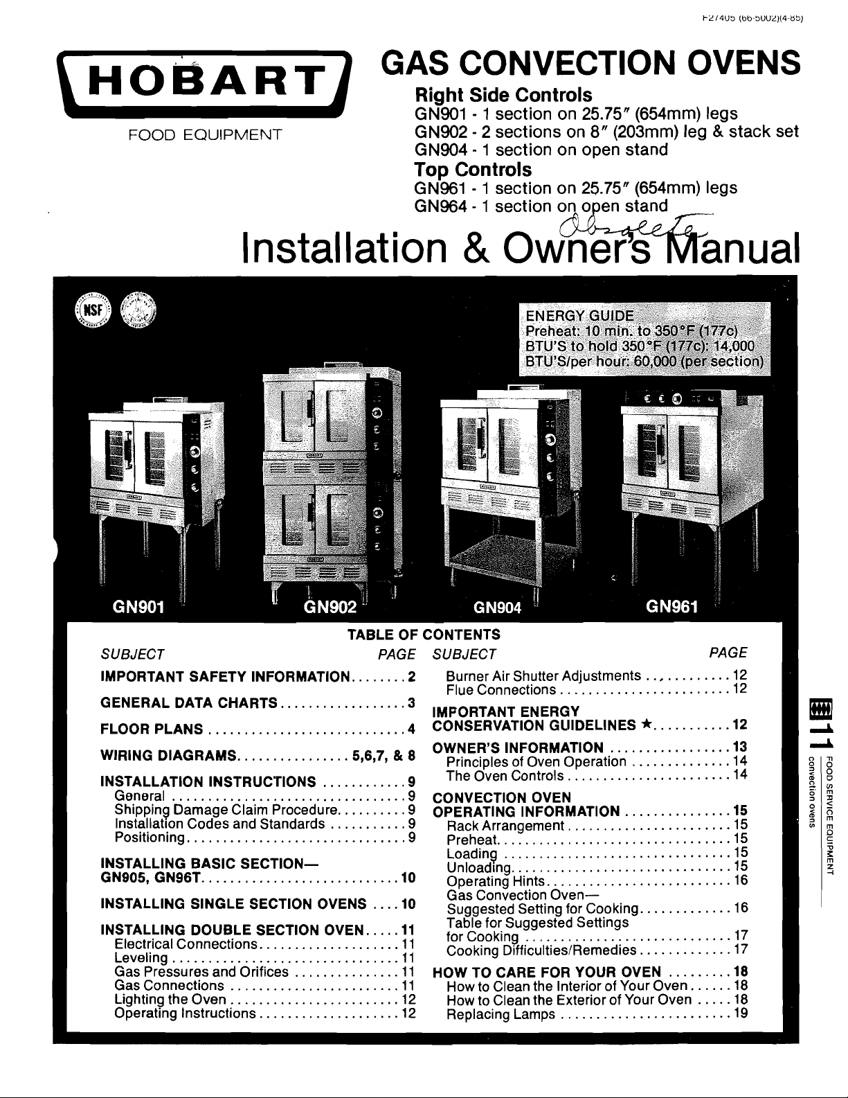
GAS
Ria
GN901 - 1 section on 25.75" (654mm) leas
ON902 . 2
GN904 . 1 section on open stand
CONVECTION OVENS
ht
V-~
Side
...
Controls
sections on
8"
(203mm)
Top Controls
GN961 . 1 section on 25.75" (654mm) legs
GN964 . 1 section
leg
&-stack set
.
.
Installation
TABLE OF CONTENTS
SUBJECT
IMPORTANT SAFETY INFORMATION
GENERAL DATA CHARTS
FLOOR PLANS
WIRING DIAGRAMS 5.6.7. & 8
INSTALLATION
General
Shipping Damage Claim Procedure
lnstallatlon Codes and Standards
Positioning
INSTALLING BASIC SECTIONGNQOS. GN96T
INSTALLING SINGLE SECTION OVENS 10
INSTALLING DOUBLE SECTION OVEN
Electrical Connections
Leveling
Gas Pressures and Orifices
Gas Connections
Lighting the Oven
Operating Instructions
............................
................
INSTRUC'rIONS
.................................
...............................
............................
................................
........................
........................
..................
............
...........
....................
...............
....................
PAGE
........
..........
2
3
4
9
9
9
9
9
10
....
.....
11
11
11
11
11
12
12
&
0
SUBJECT
Burner Air Shutter Adjustments
Flue Connections 12
IMPORTANT ENERGY
CONSERVATION GLllDELlNES
OWNER'S INFORMATION 13
Principles of Oven Operation
The Oven Controls
CONVECTION OVEN
OPERATING INFORMATION 15
Rack Arrangement
Preheat
Loading 15
Unload~ng
Operating Hints 16
Gas Convection Oven-
Suggested Setting for Cooking 16
Table for Suggested Settings
for Cooking 17
Cooking
HOW TO CARE FOR YOUR OVEN
How to Clean the Interior of Your Oven
How to Clean the Exterior of Your Oven
Replacing Lamps 19
.................................
................................
...............................
Difficulties/Remedies
........................
.......................
.......................
..........................
.............................
........................
............
...........
*
.................
.............
...............
.............
.............
.........
n ual
PAGE
-14
......
.....
12
12
14
15
15
15
17
18
18
18
Page 2
THlS MANUAL HAS BEEN PREPARED FOR PERSONNEL AUTHORIZED, QUALIFIED, CERTIFIED OR LICENSED TO INSTALL GAS EQUIPMENT, WHO SHOULD PERFORM THE
JUSTMENTS OF THE EQUIPMENT COVERED BY THlS MANUAL.
INITIAL FIELD STARTUP AND AD-
POST IN A PROMINENT LOCATION THE INSTRUCTIONS TO BE FOLLOWED IN THE EVENT
OF GAS IS DETECTED. THlS INFORMATION CAN BE OBTAINED FROM THE LOCAL GAS
IMPORTANT
IN THE EVENT A GAS ODOR IS DETECTED
SHUT DOWN UNITS AT
AND CONTACT THE LOCAL GAS COMPANY OR
GAS SUPPLIER FOR SERVICE.
MAIN SHUT-OFF VALVE
SUPPI-IER.
THE SMELL
DO NOT STORE OR USE GASOLINE OR OTHER FLAMMABLE VAPORS AND LIQUIDS IN THE VICINITY
OF THlS OR ANY OTHER APPLIANCE.
NOTE
IT IS IMPORTANT THAT YOU RETAIN THlS MANUAL FOR FUTURE REFERENCE.
Page 3
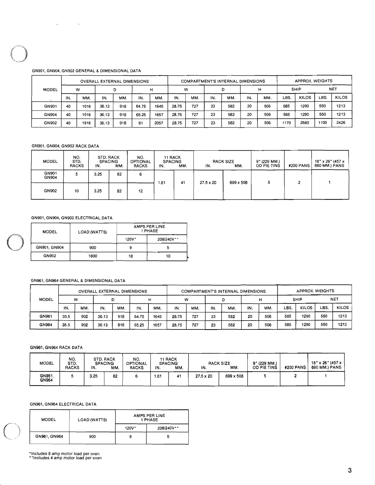
GN901. GN904, GN902 GENERAL & DIMENSIONAL DATA
GN901. GN904, GN902 RACK DATA
MODEL
GN901
GN904
GN902
NO.
STD.
RACKS
5
10
STD. RACK
SPACING
IN. MM.
3.25
3.25
82
82
OPTIONAL
GN901, GNW, GN902 ELECTRICAL DATA
MODEL LOAD (WATS) 1 PHASE
120'4' 2081240V~
GN901, GN904
GN961, GN964 GENERAL & DIMENSIONAL DATA
NO.
RACKS
6
12
AMPS PER
SPACING
IN.
1.61
LlNE
11 RACK
*
MM.
41 27.5
SIZE
RACK
IN. MM.
x
20
699 x 508
9"
(229 MM.)
OD PIE
TINS
5
#PO0 PANS
2
18" x 26" (457
660 MM.) PANS
1
x
GN961, GN964 RACK DATA
MODEL
GN961,
GN964
NO.
STD.
RACKS
5
STD. RACK
SPACING
IN. MM.
82
OPTIONAL
RACKS
GN961, GN964 ELECTRICAL DATA
MODEL LOAD (WATS) 1 PHASE
120'4' 2081240V*
GN961, GN964
'Includes 8 amp motor load per oven
"includes
4 amp motor load per oven
NO.
6 3.25
11 RACK
SPACING
IN. MM.
1.61 27.5 x 20 41 699 x 508
AMPS PER LlNE
RACK SIZE
IN. MM.
9" (229 MM.)
OD PIE TINS
5
U2OO PANS
2
18" x 26" (457
660 MM.) PANS
1
x
Page 4
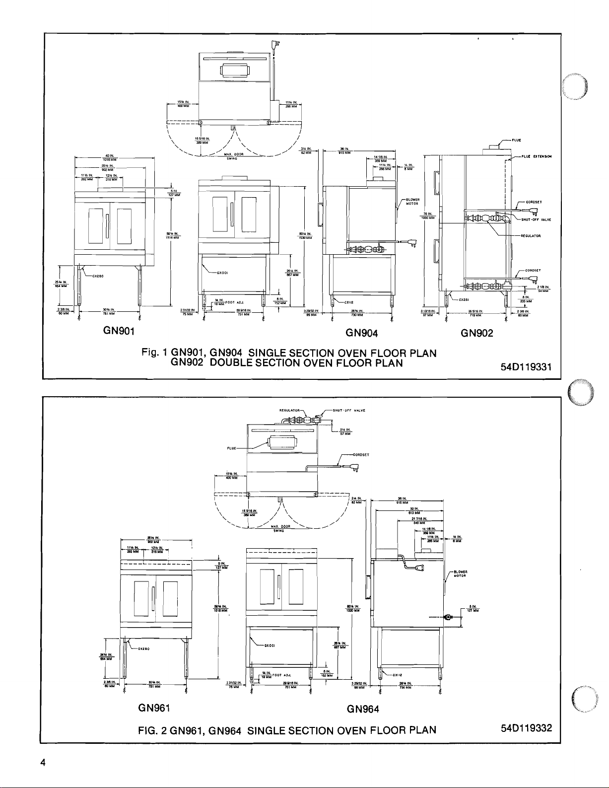
Fig. 1 GN901, GN904 SINGLE SECTION OVEN FLOOR PLAN
GN902 DOUBLE SECTION OVEN FLOOR PLAN
54D119331
GN961 G N964
FIG.
2
GN961, GN964 SINGLE SECTION OVEN FLOOR PLAN
5401 19332
Page 5
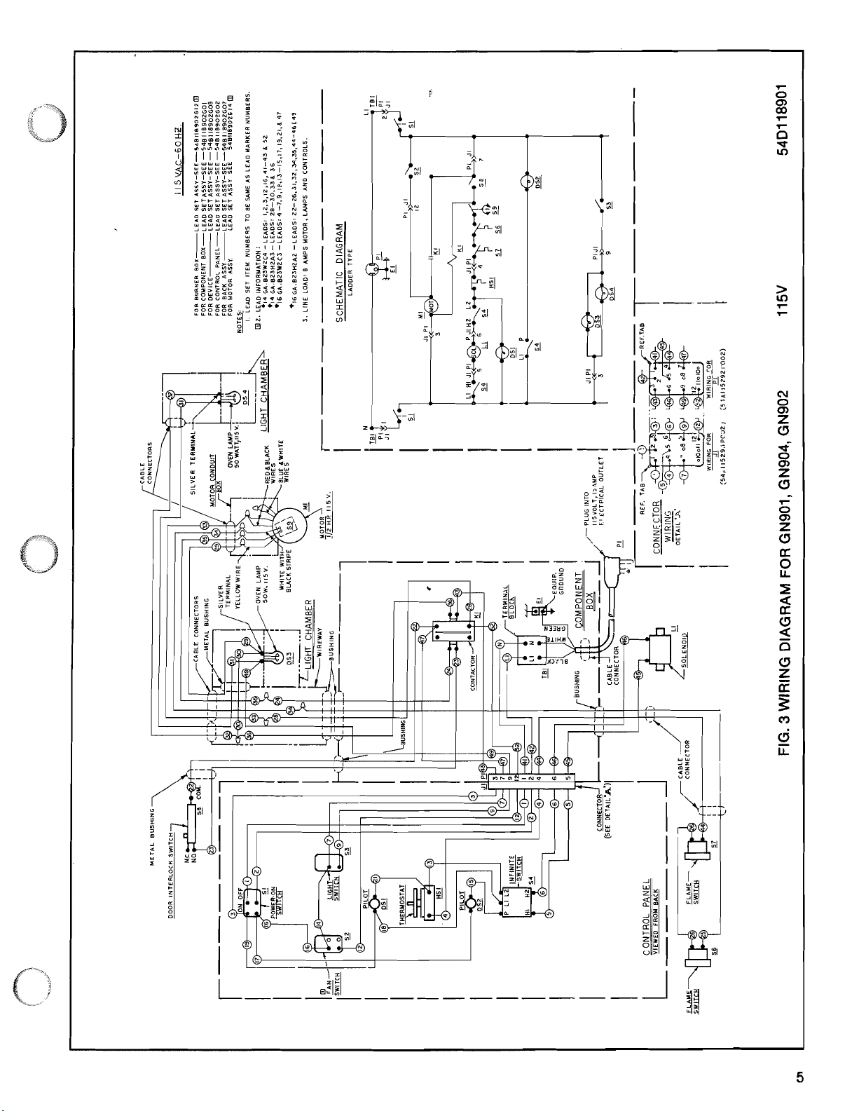
WIRING DIAGRAM FOR GN901, GN904, GN902 115V 54D118901
3
FIG.
Page 6
Page 7

V.AC -60HZ
5
11
NOTES:
ITEM NUYOERS ARE THE SAME AS
MARKER NUMBERS.
LEAD
I. LEAD
2. LEID
FOR
FMI
FOR
FOR
FOR
FOR
LINE 4 LEAD IHFORYATIOH:
3.
0231ZC4-LEADS: IJ.12.16.41-43 462
C*.
-14
-
-
SCHEMATIC DIAGRAM
1
(LADDER TYPE
--
I
SWITCH
DOOR INTERLOCK
ONNECTOR
%IRING -OETAIL~A~
I
-
--
WI:cING FOR WIFING FOR
JI~l54A115293POOZ~ ~-t54A115292P0021
-
I
EDGE
SWITCH
LCENTRIFUGAL
CHAMBER LIGHT CHAMBER
LIGHT
FIG. 5 WIRING DIAGRAM FOR GN961, GN964 115V 5401 19301
Page 8

Page 9

GENERAL
The Hobart gas oven you have purchased is a
quality product in the tradition of Hobart
fine
quality excellence. Properly installed and used it
will provide you with many years of service and
contribute to your profitable business environ-
ment.
codes or in the absence of local codes with
the National
70.1981. The 115 volt ovens are equipped with
a three-prong (grounding)
tection against shock hazard and should be
plugged directly into a
three-hole receptacle. DO NOT CUT OR REMOVE THE GROUNDING PRONG FROM
THIS PLUG.
Electrical Code ANSllNFPS No.
plug for your pro-
properly grounded
SHIPPING DAMAGE CLAIM PROCEDURE
The equipment you have received was carefully
inspected and packed by competent personnel
before leaving the factory. The company transporting the equipment assumes full responsibility
for safe delivery upon acceptance of the shipment. If the shipment is damaged:
1. Damage or Loss that is Visible
Make certain this is noted on the freight bill
or other shipping documents and signed by
\
7&&'
the person making
2. Damage Claims Should be Filed Immediately
This should be done regardless of extent of
damage. clear from combustibles.
Unnoticed Damage or Loss
If damage is noticed after the equipment is
unpacked, the transportation company or de-
livering carrier
and a concealed damage claim filed wlt
them within (15) days of date dellve
.made. The package should be kept or In
spectlon.
Hobart cannot assume responsibility for loss or
damage Incurred In transit.
INSTALLATION CODES AND STANDARDS
Hobart ovens
wlth:
1. State and local codes;
Natlonal Fuel Gas Code, ANSI-Z223.1-1980.
2.
Copies of this code may be obtained from
American Gas Assn.,
Arlington, Virginia 22209.
should be Installed In accordance
delivery.
b
should be notified lmmedlatel
i
y
Inc., 1515 Wllson Blvd.,
5. Check device nameplate to make sure that
the oven
that being
POSITIONING
Table 1 shows key general and dimensional data
all models. Consult floor plan on pages
of
for positioning and related information.
1. Combustibles in the Area
The equipment area should be kept free and
2. Clearances from Combustible
The ovens when installed should have the
followlng clearances from combustible construction:
The Flow of Combustion and Ventllatlon
The ovens must be Installed so that the flow
of
obstructed. Adequate
ings
provlded. Make sure there Is an adequate
su
p
qu
burners.
4.
Clearances for Servlclng
The lnstallatlon locatlon should also take lnto conslderatlon adequate clearances for
servlclng and proper operatlon.
voltage and type of gas agrees with
supplied.
4 & 5
Construction
Inches from the
inches from the back
combustlon and ventllatlon alr wlll not be
Into the combustlon chamber must be
ply of alr In the room to allow for that re-
red for
combustion
sldes - 6
-
6
clearance for alr open-
of the gas at the oven
Air
4-1
1%-
3. The ovens must be installed under a ventila-
-
tion hood and ventilation provided in accord-
ante
with NFPA Standard #96.
4.
The appliance when installed must be electrically grounded in accordance with local
1. Crating and packaging materials should be
removed with care.
2. The doors should not be used to
the oven.
lift or move
Page 10

These basic sections must be installed on legs
unless they are mounted on a Hobart modular
stand. Installations on concrete bases or other after being uncrated.
supports restricting air circulation on the bottom
-
will void the warranty. If a modular stand is ordered, the oven section must be set on the stand
A. Assembling the Legs to the Oven
1.
Unpack the oven and leg set.
2. Position the oven on its back, taking care
not to scratch or damage it. The motor
protrudes beyond the back; provide for
this when the oven is tipped back by resetting it on suitable spacers (2 x
3.
Attach each of the four leg assemblies to
the bottom of the oven with the
four bolts and lockwashers (6 bolts per
1
eg).
4. Place the oven in its normal attitude, on
its legs and lower it in the installing position.
5.
Attach the flue diverter over the flue vent
in the holes provided.
4's, etc.).
twenty-
Fig.
8
Installing lower flue extension
6. Attach flue trimpiece in front of the flue
diverter.
Assembling the Oven on the Stand
1.
Uncrate the oven and stand.
2. Screw two locating studs (found in stand
carton) into bottom of basic section (Fig.
7).
3.
Attach the four leg assemblies to the
bottom of the stand with the
furnished.
4. Mount basic section (Fig. 7).
5.
Attach flue diverter and flue trim to the
oven.
STAND
Fin. 7 Installation of basic oven on oDen stand
16
bolts
Fig.
9
sion.
Fig. 10 Attaching the upper flue extension
Installing middle piece of the flue exten-
Page 11

1. Unpack one oven and leg set.
2.
Rosition the oven on its back, taking care not
to scratch or damage it. The motor protrudes
beyond the back. Provide for this when the
oven is tipped back by resting it on suitable
spacers (2 x
4's, etc.).
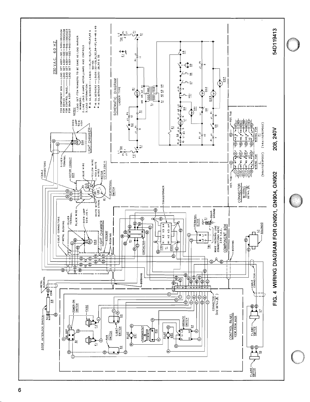
2. Refer to the appropriate wiring diagram Fig. 3,
4, 5, 6 and the information on it for making
proper line connections to the terminal block.
The 115 volt models have a cord and plug
attached and do not have to be wired. Each
of these ovens should be plugged into a
properly grounded 115 volt receptacle.
3. Attach each of the four leg assemblies to the
bottom of the oven with the twenty-four bolts
and lockwashers (6 bolts per leg).
4. Place the oven in its normal attitude, on its
legs, and lower it in the installing position.
5. Unpack the other oven, screw the two locking studs in the bottom of the oven Fig. 7.
6. Attach the flue diverter over the flue vent in
the holes provided. Screw in place.
7. Attach flue trimpiece in front of the flue
diverter.
8. Place top oven over bottom oven so that the
locating studs nest in the holes provided in
the bottom oven.
9.
Take the lower flue extension from the stack
kit and attach
oven Fig. 8.
10. Attach the middle piece of the flue extension
11. Attach upper flue extension to the upper
12. Connect the piping between the top oven
13. Leave
9.
Fig.
oven as shown in Fig. 10.
and bottom oven as shown on the floor plan
Fig. 1. Pipe compound must be suitable for
the gas being used. Check for gas leaks with
a soap and water solution.
gas valves closed until all the electrical
conne~tions are made and the ovens are
checked or used.
it to the bottom of the top
3. For 2081240 volt ovens the line leads must be
connected to the line terminal block which
may be reached by removing the wiring box
cover. Attach the ground lead to the terminal
provided.
4. Replace the wiring box cover.
5. Do not energize the power supply until after
the gas connections have been made.
LEVELING
Using a spirit level - adjust the legs to insure that
the oven racks are level in the final installed
position.
GAS PRESSLlRES AND ORIFICES
1.
"
Natural Gas
The standard orifices are set at 3.7 inch WC
(Water Column) pressure. A pressure regulator is supplied and must be installed when
the oven is connected to the gas supply.
Liquefied Propane Gas
2.
The standard orifices are set at 10 inches WC
(Water Column) pressure. A pressure regulator is supplied and must be installed when
the oven is connected to the gas supply.
GAS CONNECTIONS
1. The regulator supplied must be connected to
the manifold (note direction of gas flow
arrow).
2. The oven should be connected to the gas
line after leveling.
ELECTRICAL CONNECTIONS
1. Insure that the voltage stamped on the oven codes.
nameplate matches the available power
SUPP~Y.
WARNING
POWER AT THE MAIN CIRCUIT BOX. PLACE
A TAG ON THE CIRCUIT BOX INDICATING
ClRCLllT IS BEING WORKED ON.
THE
-
DISCONNECT THE ELECTRICAL
3. A gas shut-off valve should be installed in
the gas line ahead of the oven as required by
4. The gas supply lin'e must be at least the
equivalent of
5. Make sure the pipes are clean and free of
structions, dirt and piping compound.
3/4"
iron pipe.
ob-
Page 12

6.
IMPORTANT: All joints in the gas supply line
must be checked for leaks before lighting.
THE CHECK SHOULD BE MADE WITH SOAP
AND WATER SOLUTION (BUBBLES). AN
OPEN FLAME SHOULD NOT BE USED.
CAUTION: If burners do not light after the pilots
have been lit, check:
1.
Flame switch bulb should be hot (slightly
red).
LIGHTING THE OVEN
CAUTION: Prior to lighting, check all joints in the
as supply line for leaks. USE SOAP AND WATER
OLUTION. DO NOT USE AN OPEN FLAME.
D
OPERATING INSTRUCTIONS
1.
Open the manual valve and purge the gas
line to remove the air. Check for leaks with a
soap solution.
2. Light pilots (2) with a match or lighter rod.
1/2"
The flame should be approximately
The pilot flame will heat up the flame switch
sensing bulb.
3.
Turn on the electrical power, turn thermostat
to
max. and load control to "HI". After a brief
time the flame switch sensing bulb will heat
up and close the circuit to the
which will allow the gas to flow to the burners.
Oven door should be closed.
WARNING: Do not turn manual valves on unless
the pilots are to be lit. Before relighting pilot
lights, the manual valves must be OFF for a
minimum of five minutes.
BURNER AIR SHUTTER ADJUSTMENTS
1.
Burner air shutters should be adjusted as required. To adjust open the shutter until flame
leaves the burner port, then close slightly. Yellow
tipped flame should not be present.
2. The pilots wlll remain lit until the gas valves
are closed. If the oven
some time close the manual valve on the
oven. When the time comes to reuse the
oven, rellght the
pllots as described.
Is not to be used for
solonoid valve
high.
2. Thermostat setting.
3.
Load switch setting.
4.
Doors closed.
5.
Cool-down switch is off.
If burners still do not light, turn off the manual
valve and call a qualified servicer.
FLUE CONNECTIONS
Ventilation requirements will vary with each installation and must comply with applicable portions National Fire Protection Association Standard
#96
and with local codes. Considerations
to be kept in mind include:
1.
Flue connections should never be made directly to the oven.
2. The oven should be located under a hood
with an adequate connection to an exhaust
6
duct and having a
the oven sides.
3.
Clearance above the oven flue should be
adequate for the flue products to escape so
that there is no interference with the heat circulation In the ovens. Refer to the Standard
for the
moval of Smoke and
from Commerical Cooklng Equlpment, NFPA
Standard
4.
Conditions
the kitchen
wlndows next to the oven or fans blowing
dlrectly on the oven should not be allowed to
exlst.
5.
To prevent the oven function from belng
affected by a reduced atmospheric pressure,
adequate make up alr In the kltchen should
be
the ventllatlng system.
lnstallatlon of Equlpment for the Re-
#96.
resulting
-
such as wall type fans, or open
provided to replace the alr taken out by
inch extension beyond
Grease.Laden Vapors
In cross currents within
1.
Purchase properly sized equipment for your
operatlon; don't overslze or undersize.
2. Don't oversize ventilating system. Use the
size that will provide optimum air flow.
3.
Turn off unused equipment.
4.
Reduce thermostat settings In slack periods
slnce gas equipment heats up, recovers fast.
-
5.
Ad'ust menu patterns and cooking and baking
sc
A
edules: for optimum equipment use.
*Based on National Restaurant Association's
"Check-List for Energy Control and Conservation".
Page 13

Five standard racks per
section measure 27.5" x
"
(670 x 508 mm).
20
Cool to touch handle 200 pans. Six additional
Each rack holds two No.
opens both doors 180 racks optional for
non-
degrees, simultaneously. rising products.
Recycler recirculation system saves
approximately 40% in gas energy
costs by reusing already heated air.
INTERIOR: Porcelain panels over
stainless steel liner. Inner door liner
stainless steel.
Six-sided insulation (top, bottom,
sides, back and front) for high energy
efficiency.
Positive stops hold loaded racks securely when two-thirds withdrawn.
Automatic interlock switch shuts off
blower motor and burners when
doors are opened.
Two interior lights turned 'on by separate switch for in-process inspection.
Motor-driven blower fan constantly
circulates forced air for fast,
high-
loading, volume cooking.
cuts heat loss
for greater en-
ergy efficiency
and is more
sanitary and
virtually trouble-free.
M
Long-life energy-efficient
HP 1725rpm motor has sealed ball bearings,
needs no lubrication for 10 years.
Front-service access.
Fan switch allows operating the
blower when door is open for quick
cool down.
Interior temperature cycle varies
~t
only
10F.
Page 14

W
PRINCIPLES OF OVEN OPERATION
The heating of the oven involves the following:
1. Two tubular sheet
combustion chamber that is insulated.
2.
Above the combustion chamber is the flame
chamber which collects the heat coming
from the burners.
3.
The collected heat is directed through heat
exchanger tubes located in the cooking com-
partment. The oven compartment is first
heated indirectly by the heat from those
tubes.
4.
Heated flue products are then collected in a
chamber above the oven compartment,
drawn back into the oven and recirculated by
the blower wheel throughout the compartment.
5.
The fan distributes the heat throughout the
oven cavity.
W
THE OVEN CONTROLS
The control panel on the
mounted on the top and on the
section is mounted on the side. In both arrangements, the control functions are the same as
described
below.
metal burners operate in a
GN96T basic section is
GNSOS basic
Power
@
ON-OFF Switch. Energizes the oven controls
electrically.
@
Load Control. 'This is an infinite type control
which varies the input between
percent.
OFF
PERCENT OF
CONTROL SETTING FULL INPUT
HI-7
6
5
4
3
2
LO
-
1
OFF
@
Load Control Signal Light. When the light is
on, it indicates the
ing in the range between HI and LO settings.
@
Thermostat. This is a snapaction type control
of the temperature from
control
@
Thermostat Slgnal Llght. When the signal
light is "ON" it shows that the oven is preheating or is recovering to the termperature
dial settings
activatesldeactivates the burners.
while In a cooling cycle.
load control is function-
200'F
to
500'F.
and 100
This
I
CONTROL PANEL ON GN96T
I
CONTROL PANEL ON GN9OS
@
Tlmer. Any time interval can
one hour. The tlmer
val when the set time Is reached. The duration
of the timer rlng depends on how much the
tlmer has been wound.
@
Oven Llght Swltch. The oven lights are controlled by a rocker switch. To prolong
bulb Ilfe, use Ii hts only when loadlng the
oven, checking t
@
Automatlc Interlock Swltch (not vislble). Thls
switch shuts off the blower motor and burners
when the doors are opened except as noted
Item 9.
In
@
Cool Down Fan Switch. Thls swltch allows
the operatlon of the fan only (not the burners)
to cool down the oven
doors are o en. (See the para raph 1, page 18
Cool the &en to Clean un er the section
How to Care for Your Oven.)
will rlng for a short lnter-
1
e product or unloadlng.
be
selected up to
rapldly when the
8
llght
Page 15

6~
f@-)
k.
RACK ARRANGEMENT
The oven has eleven rack positions and five
racks are furnished with it. Additional racks are
available as optional accessories. The rack arrangement to be used for a cooking run will be
determined by the height of the particular product
being cooked. Thus the racks on which the product
will be placed may have one, two or more unused positions between them. For example,
cookies which have very little height can be
placed on 18 x 26 pans on each of the eleven
rack positions. Turkeys and other roasts with
considerable height would be placed on the
lowest positions
(#5
or #6).
PREHEAT
Followin are the steps to be followed in pre-
heating t e oven.
1.
2.
3. Set the thermostat dial to the temperature at
4.
5. Turn the Power Switch to "ON".
6.
R
The proper rack arrangement should be made
for the product to be cooked. (Refer to the
previous section.)
Your oven operates only when the doors are
closed. An electric interlock is provided that
de-energizes the blower and the burners
whenever the oven door is opened.
which the product will be cooked. Regarding
the temperature setting, the following Is
suggested. Since the oven chamber opening
is large and loading to capacity necessitates
keeping the doors open longer than Is usual
with standard ovens, temperature drops will
take place. To offset
while preheating, before the food is intro-
duced, the
the temperature at which the foo s
cooked.
Set the load control to HI.
The slgnal light will come on and stay on
until the set tem erature
preheat time is
350°F. The oven should be allowed to cycle
twice before loading for baklng to assure
good heat saturation of the oven chamber.
NOTE: Remember to set the thermostat to
desired cooking temperature if a higher
temperature was used to preheat the oven.
(#I) and the half-way position
this it Is suggested that
dial setting be 50°F hi her than
will be
B
1
g
mlnutes at a setting of
Is reached. Thls
7.
Under normal operating conditions, the
blower will continue to operate at all times
when the oven is on, except when the oven
doors are opened.
LOADING
With the oven preheated as noted above, it is
ready to proceed with the cooking.
1.
Open the doors (the fan will stop) and load
quickly. The pans should be centered on the
racks.
2.
When loading has been completed, close the
doors.
all cases, the oven should be loaded as
quickly as possible, keeping the door open
for the shortest possible period.
3. With the food in the oven chamber, reset the
temperature dial setting to what is appropriate
for the particular food product.
4.
Set the load control to the recommended
setting for the product and load to be cooked.
Refer to the Suggested Cooking Chart for
"
specifics.
5. Set the timer to the suggested time. A ain
refer to the Suggested Cooking Chart.
timer Is strict1 a mechanical one - IT IN NO
WAY
OVEN OR TURNS IT OFF. To insure that it
will ring when the time at which it was set
has elapsed, wind the timer to the maximum
setting. Then back-up to the desired setting
for the product. This will result in spring
tension sufficient to activate the alarm.
6.
When the cook time has elapsed, check for
proper doneness. If the food is done to your
satisfaction unload; if not set for additional
time and cooking as required.
UNLOADING
1.
Since convection ovens are high production
devices, consider the space that will be
needed to accommodate the food to be unloaded from the oven.
2.
Unloading should be fast to minimize the
heat loss while the doors are open
essential practice if consecutive cooking
loads are to be made.
3.
If consecutive loads are to be cooked, it is
suggested the doors be closed between each
load so the oven can recover to the preset
temperature.
'The blower will resume operation. In
%he
CONTR~LS
THE FUNCTION
OF THE
-
an
Page 16

OPERATING HINTS
Although some of the following points have been
touched on, they are mentioned again for their
significance.
1. When using the convection oven for the first
time with a particular food, check the degree
of doneness periodically before the suggested
time has elapsed, to make sure the desired
doneness is achieved.
2. Your own tables of temperature and times for
the various products should be completed,
as the oven is used, to reflect your own
operation.
3. Because the convection oven moves forced
heated air around in the oven chamber, the
temperature setting for the various products
are lower and the cook times are shorter than
in a conventional deck-type oven. Since recipes and foods are subject to many variations
and tastes, the recommendations about temperature settings and cooking times contained in this manual are SUGGESTIONS ONLY.
You, the operator, should do some experimenting in the beginning with your food products, since the oven may open up new vistas
of cooking for you, to find what temperatures
and times give you the best results.
4.
Do not open the doors unless it is necessary.
The windows on the doors allow product inspection without necessitating door opening.
There's adequate lighting, too
that go on when needed by turning the light
switch on the control panel.
-
two lights
In the table the temperatures are shown in
The indication on the dial is in both OF and "C as
shown in -Fig. 11.
Fig. 11 The temperature dial
'The load control varies from LO to HI as shown
in Fig. 12.
OF.
5. Load racks evenly and center the pans on
them. Keep them toward the front, to avoid
the possibility of light foods being thrown on
the motor fan.
6.
Use interior lights sparingly.
GAS CONVECTION OVEN - SUGGESTED SET-
TINGS FOR COOKING
The following Table 4 shows sug ested settings
of Temperature, Load Control and
products. These settings are intended as suggestions only since results depend on numerous
variables such as variations and content of the
food, recipes and preferences of the users.
In meat roasting it may be desirable to take
some steps to reduce shrinkage. In addition to
cooking meat at low temperatures (per the recommendations of USDA and the American Meat
Institute beef, lamb, and poultry should be cooked
at 225°F to
moisture in the cavity can be retained by placing
a shallow (1" deep) pan with water in the bottom
of the oven.
325"F, fresh pork at 325°F to 350°F)
7
ime,for various
4
MED
Fig. 12 Load Control
Page 17

TABLE 4 - SUGGESTED SETTINGS FOR COOKING
PRODUCT PRODUCT TEMPERATURE
CATEGORY PRODUCT DESCRIPTION
MEAT
FOWL
FISH
BREAD PRODUCTS
PASTRIES
Hamburger patties
Rolled rlb roasts
Standing rib roasts
Veal Roast
Steamship round Whole 6080 Lbs.
Meat Loaf 8-10 Lbs.
Turkeys
Chicken
2.2M Lbs.
Chicken
2.2112 Lbs. Backs 8 Wings
Fish stlcks 20.7. % X3"
Halibut steaks
Lobsters
Lobster tails
Bread-loaf 1 Lb.
(
Rolls
I
Rolls 2% Oz.
I
Biscuits
Muffins
Corn Bread
Sheet cakes
Angel cakes
Sugar cookies
Frult'pies (Frozen)
Apple pies (Fresh)
Pumpkin ples
Apple turnovers
2 Oz.
2.5 02.
4
02.
2022 Lbs.
15-20 Lbs. 300 3 Hr.
Breasts 8 Thighs 35
Breaded Fr
5 Oz. Fr.
1
M
Lb.
Y4
Lb.
Lbs118 x 2 6
7
26 Oz.
0.7.
20
x
1
Pan
(OF)
400-450
400450
375-400
1
?$
3M)
/
I I
I
335
56
7.10
8.12
1
l.%r. (Rare)
4-45 Hr. ,Me\
3 ~r. (~e'd)
1
45.60
33
i:
I
$:
TIME LOAD NO. OF
(MINUTES) CONTROL RACKS
4-6
6
5
283
6
46
5
283
7
46
5
283
7 3
1
'
1314
2
I
2
5
5
4
5
5 (24
5 (30 Pies)
5
5
2-PanlRack
Pies)
MISCELLANEOUS
Oven preheat Is proper but oven
never recovers from temperature
drop after food Is put In.
Edges of pans over-cooklng or very
uneven
browning.
Food
epllllng or
an
edge.
Overbrownlng or
Shrinkage very hlgh.
Melted cheese sand.
Pizza (Frozen)
Idaho potatoes
Frozen
TV
dinners
02. foil meals
Frozen 8
Frozen entrees (1" thick)
COOKING DIFFICULTIES AND SUGGESTED REMEDIES
DIFFICULTY PROBABLE CAUSE REMEDY
"running"
ahrlnklng.
towards
120 count150 Lbs.
100 count150 Lbs.
Count150 Lbs.
80
Load too big.
1.
Load control setting too high.
2.
Too many racks.
1.
Oven not leveled.
2.
Warped sheet pans.
Load control setting too high.
1.
Roasting temperature high
2.
Oven moisture low.
5 (120)
5
5
5
5
5
5
5
Check cooking chart for proper
loading.
Check Cooking Chart for proper
settings and loads.
1.
Level ovens on the racks both
front to back and side to side.
2.
Remove warped pans from the pan
set used for baking. Keep baking
pans separate from the others.
Lower the load control setting. Refer
to Cooking Chart.
1.
Reduce oven temperature.
2.
Put water in shallow pan
bottom.
on
oven
Page 18

W
HOW TO CLEAN THE INTERIOR OF YOUR
OVEN
Cool the Oven to Clean
Always allow oven to cool prior to cleaning.
To speed up the cooling, a Cool Down Fan
Switch is featured on the oven. In the Cool
Down position only, the blower will operate
when the doors are open. If the oven is still
hot make sure the fan is turned on with the
doors only slightly ajar to minimize the ex-
posure of the operator to the current of hot
air.
2.
Do Not Allow Large Accumulations
Keep the inside of the oven and racks wiped
clean. If food
so doors cannot be tightly closed, heat is
wasted and the oven will not operate properly.
Poorly closed doors permit a constant escape
of steam and vapor around the door.
causes a condensatioin which deteriorates
the finish around the oven front and door
lining.
3.
The Porcelain Liner Panels
Clean often when the oven in cold with mild
detergent or soa and water. This will prevent
food and dirt
frequently be all the cleaning that is necessary. Where soil resists soap-water clean-
ing, use a wooden tool to loosen
from the cold oven. Follow with a non-etching
cleaner which
procelaln enamel. Use clear water to rlnse;
for
d wlth a soft clean cloth. DO NOT USE
S~EEL
SOLUTIONS such as lye, soda ash, or
monla.
WOOL. WIRE BRUSHES and CAUSTIC
articles
P
rom "baking on" and will
Is specifically recommended
or carbon accumulate
splllage
'This
am-
foods and grease which resist simple
water cleaning, an abrasive cleaner such as
Bon Ami or Ajax, mixed into a paste, may be
employed. Apply with stainless steel wool or
sponge, always rubbing with the "grain".
This treatment is equally effective for "heat
tint" (slightly darkened areas caused by oxidation). Again, remember to rub in the direction of the polish lines. Rinse with clear wa-
ter, and dry with a soft cloth.
6.
The Recycler Tube
This tube should never be blocked. It should
be kept clean at all times for proper operation of the oven.
7.
Odors In The Oven
Low temperature cooking mayVresult in lingering odors. They can be eliminated by setting the thermostat at 500°F and the load
control at HI, and running the oven for half
an hour.
H
HOW TO CLEAN THE EXTERIOR OF YOUR
OVEN
Washln!
Wash al exterior surfaces at least once daily.
Use a cloth with warm water and a mild soap
or detergent. Where surfaces have been pol-
-
ished, use a cloth lightly
remove
dry. This simple beauty treatment not only
keeps your equlpment
but virtually ellminates the danger of grease
accumulation
remove stain
pollsh. Follow with a clear rlnse, then
-
which may form a hard-to-,
If left on too long.
hard rubbing will
dlrt-free and sparkling,
soap-
4.
The Llner Itself
The
porcelain
and should be removed periodically to check
for build-ups
air circulation and heat transfer, keep the
area around the heat exchange tubes clean.
The Stainless Steel Door Liner
5.
Soap or detergent and water will usually take
care of routine cleaning. Drying is accomplished with a soft clean cloth. For burnt-on-
liner side panels are removable
-
salt, batter, etc., For proper
Permalucent Flnlsh - Exterior Slde Panels
If rease has accumulated on the PERMALU 8 ENT flnlsh, remove It with any siliconbase polish, follow dlrectlons on the container. NEVER use a scouring pad-type
cleaner on the PERMALUCENT finish. If the
surface should be accidentally marred, it can
be quickly and easily restored to its original
beauty with a "PERMALUCENT Touch-Up-Kit",
available through your Hobart Chicago
Heights
each kit.
Servicer. Full instructions are in
Page 19

3.
Cleaning The Stainless Steel
To keep the stainless steel front bright and
gleaming at all times, just clean it regularly
with a damp cloth and polish with a soft, dry
cloth. To remove discolorations which may
have formed when regular
glected, use any detergent or plain soap and
water. For
a self-soaping scour
CAUTION: ALWAYS RUB WITH THE "GRAIN"
IN A HORIZONTAL DIRECTION.
4.
Plastlc Control Knobrr
Waah, d and pollsh with a soft cloth. Avoid
uslngl grl 7 ty soepsl or harah cleaners.
I
REPLACING
1.
Ctr@~k
2.
WARNING turn off electrlc aupply.
particular1 stubborn discolorations,
Y
ng pad may be used.
LAMPS
to
aneure
that the oven Is cool.
cleanlng was ne-
R~rnava
up
4,
ffcllm~v@
5.
Part1
6,
Rtaylace the burnt-out bulb,
7,
Replace the hardware by reversing the dls-
rrmombly procedure.
all rack5 by pulling forward, lifting
and
out.
screws from the llght window bezel.
out the bezel and wlndow.
b
Page 20

As
continued
changed without notlce.
product Improvement Is a pollcy of Hobart, speclflcatlons may
be
14th &Arnold Streets Chlcago Helghts, IL 60411
HOBART CORPORA'I'ION
PRINTED
IN
U.S.A.
 Loading...