

Page 1

DDU38 DIRECT DRIVE UNLOADER
R-L OPERATION L-R OPERATION
ML-110564 ML-110565
701 S. RIDGE AVENUE
TROY, OHIO 45374-0001
FORM 33690 (6-97)
Page 2

Installation Instructions
DDU38 DIRECT-DRIVE UNLOADER
GENERAL
The DDU38 Unloader is connected to the unload end of a C-Line A, W, or AW dishwasher. It moves
the 20" x 20" rack in a 90 degree arc onto a dish table. The Unloader uses a direct linkage with the
dishwasher cradle to oscillate the rack-moving mechanism.
NOTE: The Unloader cannot be installed on dishwashers having either the Blower Dryer or the framemounted Electric Booster Heater options.
INSTALLATION
UNPACKING
Immediately after unpacking, check for possible shipping damage. If the Unloader is found to be
damaged, save the packaging material and contact the carrier within 15 days of delivery.
LOCATION
CAUTION: Do not use a forklift to move or unskid machine.
Place Dishwasher and Unloader as close to their final positions as possible. Review all tags and labels
but do not remove any until installation is complete. Remove any packaging, tape, wire, and bracing.
ASSEMBLY
Leg Installation and Leveling
Insert the long legset into the two rear leg
sockets underneath the Unloader (Fig.1).
Insert the short legset into the two front leg
sockets. Fasten legs to leg sockets by
loosening and tightening the set screw in
each leg socket. Fill set screws with an NSF
approved silicone sealant.
Make sure adjoining parts of Dishwasher and
Unloader are exactly in line with each other.
Turn leveling feet (on bottom of legs) in or out
to adjust height and level machine. Also,
refer to Track Guide Leveling, page 6.
UNLOADER
LEG SOCKETS
DRAIN
LEVELING FEET
DISHWASHER
PL-52426
© HOBART CORPORATION, 1997
Fig. 1
– 2 –
Page 3
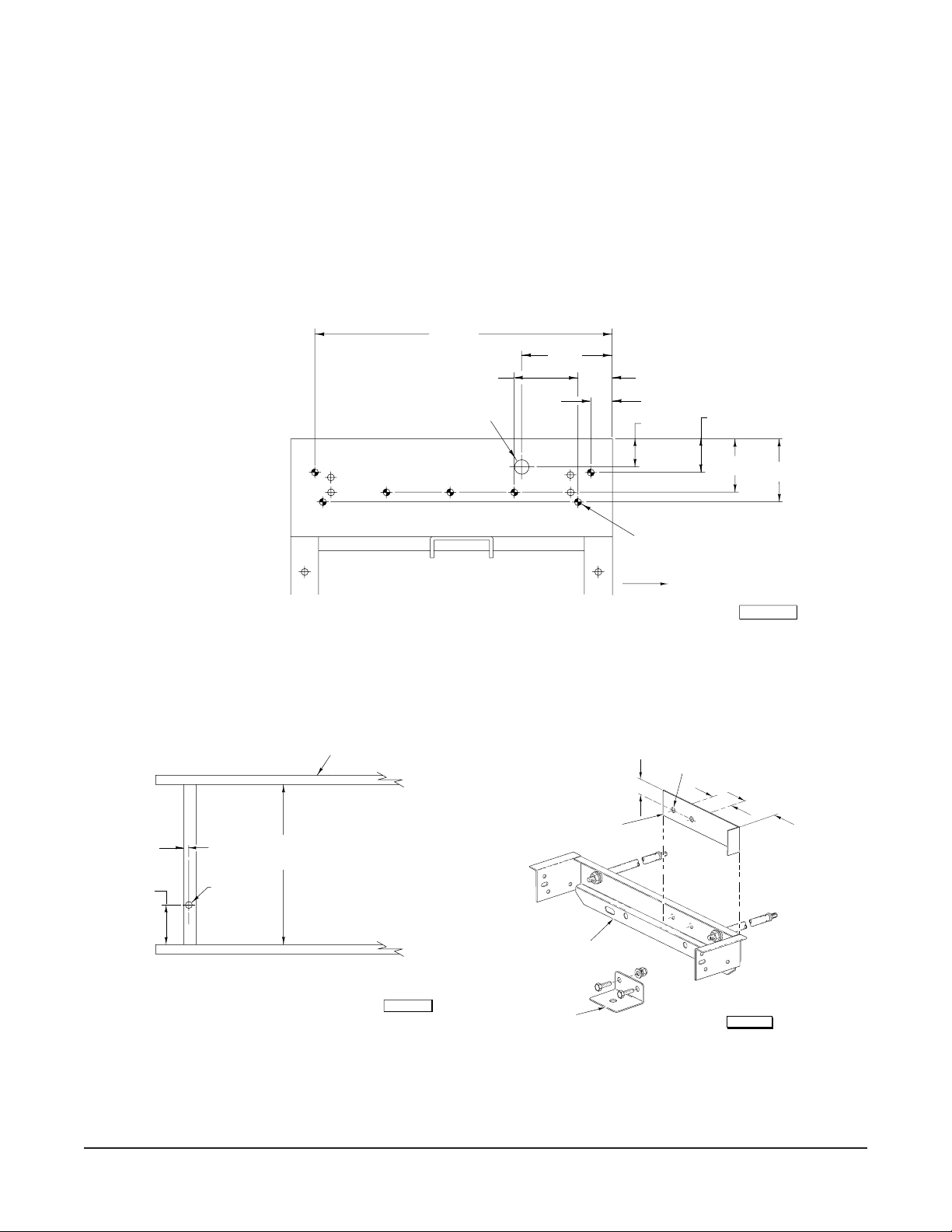
Drill Holes
If the Dishwasher was not specified for installation with a DDU38 Unloader, the mating holes may not
be present and must be drilled.
Refer to Figs. 2 & 3 for Right-to-Left Operation. Refer to Figs. 4 & 5 on page 4 for Left-to-Right
Operation. Templates are provided.
Right-to-Left Operation
23-11/16
7-9/32
5.000
4 PLC
1.000 DIA.
HOLE
2-5/8
1-17/32
2-1/4
5/16 DIA.
7 HOLES
2-11/16
2 PLC
4-1/8
3 PLC
4-7/8
2 PLC
15/32
3-15/16
18-3/16
INSIDE
REF.
11/32 DIA.
HOLE FOR
R-L OPER.
FRONT OF DISHWASHER
LEFT "UNLOAD" SIDE OF DISHWASHER
Fig. 2
CRADLE
PL-52428
BRACKET
TEMPLATE
CRADLE
FRONT
7
/8
11
/32 DIA.-2 HOLES
1 3/4
FRONT
PL-52758
PL-52427
1
3
/8
All C-Line A Models Except C54A-Series C54A-Series Only
Fig. 3
– 3 –
Page 4

Left-to-Right Operation
1-17/32
2-1/4
5/16 DIA.
7 HOLES
4-7/8
2 PLC
2-11/16
2 PLC
4-1/8
3 PLC
2-5/8
7-9/32
5.000
4 PLC
23-11/16
1.000 DIA.
HOLE
CRADLE
FRONT
18-3/16
INSIDE
REF.
11/32 DIA.
HOLE FOR
L-R OPER.
RIGHT "UNLOAD" SIDE OF DISHWASHER
Fig. 4
1
3
/8
15/32
3-15/16
PL-52429
11
/32 DIA.-2 HOLES
1 3/4
7
/8
TEMPLATE
CRADLE
FRONT OF DISHWASHER
PL-52430
FRONT
BRACKET
All C-Line A Models Except C54A-Series C54A-Series Only
Fig. 5
– 4 –
PL-52755
Page 5

Assemble Three Splash Guards, Apply Foam Tape, and Assemble Unloader-to-Dishwasher
1
Use 1
/2" foam tape (supplied) to make a watertight seal where the Unloader bolts to the Dishwasher
(Fig. 6). Assemble the unload end of the Dishwasher with the load end of the Unloader using six
1
/4" - 20 x 5/8" bolts, lockwashers, and nuts (provided). Refer to the paragraph after the next paragraph
regarding the seventh, upper-front, hole.
Three splash guards are provided in the bag of loose parts. Install the two splash guards with slotted
holes between dishwasher and unloader by bolting them to the end of the dishwasher chamber (Fig. 6).
1
Use the lowest hole on the chamber end as the bottom hole. Assemble using two
/4" - 20 x 5/8" screws,
lockwashers, and nuts (provided).
The smaller splash guard with round holes goes inside the unloader tank near the front corner (Fig. 6).
This splash guard uses the upper hole nearest the front of the seven holes that join the Unloader to
the Dishwasher. Assemble the smaller splash guard using one
1
/4" - 20 x 5/8" screw, lockwasher, and
nut (provided) — the screw goes through the bottom hole of the splash guard, the wall of the Unloader,
the Foam Tape, and the tank of the Dishwasher.
Right-to-Left Operation Left-to-Right Operation
FOAM TAPE
FRONT
FRONT
PL-52754
LEFT "UNLOAD" SIDE OF DISHWASHER RIGHT "UNLOAD" SIDE OF DISHWASHER
Fig. 6
– 5 –
Page 6

Direct Drive Linkage
Your Hobart service technician should assemble the linkage from the drive mechanism on the Unloader
to the Cradle of the dishwasher. The distance between the centers of the screws holding the drive rod
to the Unloader and the Cradle should be 113/32". If the 113/32" dimension is not present, turn the
Adjustable End on the Drive Rod until the dimension is present (Fig. 7). The bolt, washers, spacer, and
stopnut, (provided) should be assembled through the hole in the top of the Cradle and the Adjustable
End (Fig. 7) on all models except C54A Series. On C54A Series only, mount the bracket to the cradle
using two
5
/16" - 18 x 3/4" bolts, lockwashers, and nuts (provided) and assemble the Adjustable End to
the bracket with the bolt, washers, spacer, and stopnut (bottom view, Fig. 7). During assembly, your
Hobart service technician should apply a small amount of Neverseez graphite lubricant (not supplied)
on the spacer.
Right-to-Left Operation Shown
11-3/32"
ADJUSTABLE ENDDRIVE ROD
Fig. 7
Assemble Dish Table to Unloader
Assemble a suitable dish table (not included) to the discharge
end of the Unloader. Use suitable fasteners, such as two or
more stainless steel
5
/16"-18 x 5/8" machine screws,
lockwashers, and nuts (not provided) (Fig. 8). Use silicone
sealer or 1" foam tape between dish table and tank lip on
Unloader to make a watertight seal. The dish table should
tilt so it drains into the Unloader.
BRACKET
5/8"
CUSTOMER'S
TABLE
QUANTITY & LOCATION
OF MOUNTING HOLES
AND HARDWARE
BY OTHERS
BOLT
WASHER
SPACER
WASHER
STOPNUT
PL-52433
Fig. 8
CRADLE
C54A SERIES
CRADLE
7/8"
DDU38 TANK END
PL-52434
Track Guide Leveling
The track guides on which the rack rides should be even or slightly lower as the rack progresses from
the Dishwasher to the Unloader and from the Unloader to the dish table. Your Hobart service technician
can make any necessary adjustments.
– 6 –
Page 7

Assemble Table Limit Switch to Dishtable
The exact location of the Table Limit Switch (provided) is customer selectable. It may be mounted
either at the end or on the back of the dish table. When mounted on the back of the dish table, space
for at least three racks (60 inches) is usually provided.
Drill holes in the dish table at the proper location for mounting the Table Limit Switch. Refer to Fig. 9
for Right-to-Left operation. Refer to Fig. 10 for Left-to-Right operation.
Right-to-Left Operation Left-to-Right Operation
7/32" DIA.
2 HOLES
7/32" DIA.
2 HOLES
1/2" DIA.
2 HOLES
1-1/2"
3/4"
BOTTOM OF
DISH TABLE
1-1/2"
3/4"
1/2" DIA.
2 HOLES
BOTTOM OF
DISH TABLE
PL-52435
13/16"
PL-52439
13/16"
Fig. 9 Fig. 10
Disassemble actuator by removing two screws (Fig. 11). Save actuator and screws for reassembly
after switch is mounted.
Remove two screws, lockwashers, and nuts from switch bracket and reuse in mounting switch to dish
table through two
7
/32" diameter holes (Fig. 11). Reassemble actuator through two 1/2" diameter holes
in dish table. Reinstall actuator on hinge using two original screws (Fig. 11).
MOUNT SWITCH
REMOVE AND SAVE
TWO SCREWS,
LOCKWASHERS AND NUTS
ACTUATOR
REMOVE AND SAVE TWO
ACTUATOR SCREWS
USING TWO SCREWS,
LOCKWASHERS AND NUTS
THRU 7/32"DIA. HOLES
ACTUATOR
ASSEMBLE ACTUATOR
WITH TWO SCREWS
THRU 1/2" DIA. HOLES
SECURE WIRES WITH
STRAIN RELIEF AS SHOWN
RIGHT TO LEFT OPERATION SHOWN
(LEFT TO RIGHT OPPOSITE)
Fig. 11
– 7 –
PIGTAIL
LEADS
PL-52436
Page 8

PLUMBING CONNECTION
WARNING: PLUMBING CONNECTIONS MUST COMPLY WITH APPLICABLE SANITARY, SAFETY,
AND PLUMBING CODES.
Drain
The drain fitting (1
1
/2" NPT internal threads) underneath the Unloader (Fig.1) should be properly
connected to a suitable drain.
ELECTRICAL CONNECTION
WARNING: ELECTRICAL AND GROUNDING CONNECTIONS MUST COMPLY WITH THE
APPLICABLE PORTIONS OF THE NATIONAL ELECTRICAL CODE AND/OR OTHER LOCAL
ELECTRICAL CODES.
WARNING: DISCONNECT ELECTRICAL POWER SUPPLY AND PLACE A TAG AT THE
DISCONNECT SWITCH INDICATING THAT YOU ARE WORKING ON THE CIRCUIT.
1
Run
/2" conduit containing three #14 AWG insulated wires rated 90°C and 600 volt from the Table Limit
Switch to the control box on top of the dishwasher. Conduit and wires should be UL listed . When
routing conduit on gas heat dishwashers, provide a minimum clearance of 10 inches around the flue.
The installer should connect the Common, Normally Closed and Normally Open pigtails at the Table
Limit Switch; pigtail leads should be looped through strain relief to make secure (Fig. 13). The installer
should NOT connect the wires in the dishwasher control box. Only a properly trained Hobart service
technician should make the final wire connections in the dishwasher control box.
FORM 33690 (6-97) PRINTED IN U.S.A.
– 8 –
 Loading...