

Page 1
D340 MIXER
TECHNICAL MANUAL
(ML-134254)
(208/60/3)
SPECIFICATION SHEET
INSTALLATION INSTRUCTIONS
OPERATION INSTRUCTIONS
CLEANING INSTRUCTIONS
MAINTENANCE INSTRUCTIONS
TROUBLE SHOOTING INSTRUCTIONS
WIRING DIAGRAMS
CATALOG OF REPLACEMENT PARTS
SMARTPARTS™ USER GUIDE
RECOMMENDED SPARE PARTS LIST
Page 2

D340 Mixer Technical Manual Page 2 of 67
Need other Hobart Services?
Warranty Registration
Delivery and Installation
Preventive Maintenance
Hobart Service Contracts
Extended Warranty Contracts
Parts and Accessories
Specialty Programs
Water Treatment Programs
Air Filtration System
Page 3
Item # ________________________________
D340 Mixer Technical Manual Page 3 of 67
Quantity_______________________________
C.S.I. Section 11400
D340
701 S Ridge Avenue, Troy, OH 45374
1-888-4HOBART • www.hobartcorp.com
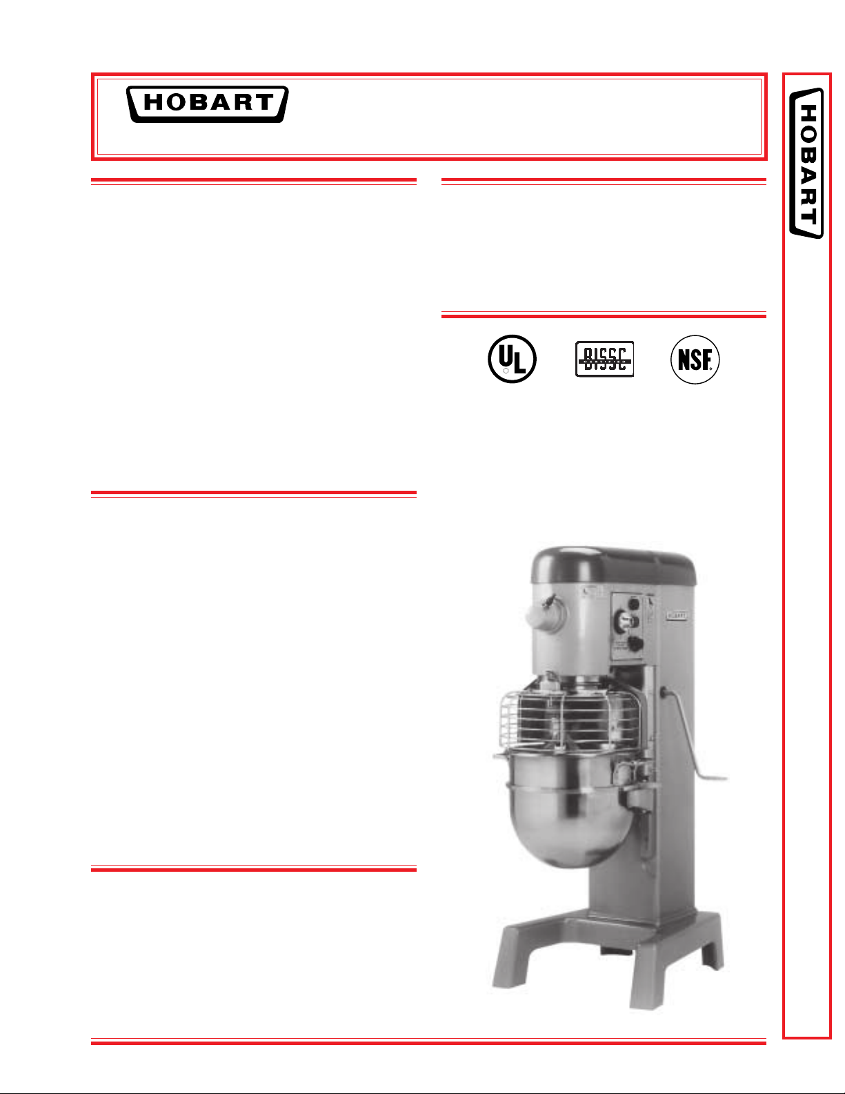
STANDARD FEATURES
■ 11⁄2 H.P. Hobart Designed Fixed Speed Motor
■ Gear-Driven Transmission
■ 15 Minute Timer
■ Three Fixed Speeds
■ Open Base
■ Large, Easy-To-Reach Controls
■ #12 Taper Attachment Hub
■ Stainless Steel Bowl Guard
■ Manual Bowl Lift
■ 40-Quart Stainless Steel Bowl, “B” Flat Beater,
“D” Wire Whip, “ED” Dough Hook
ACCESSORIES
MIXER
MODELS
❑ D340 – 40-Quart All Purpose Mixer
❑ D340C – 40-Quart All Purpose Mixer with
Maximum Security Correctional
Package (208/60/1 and 208/60/3 only)
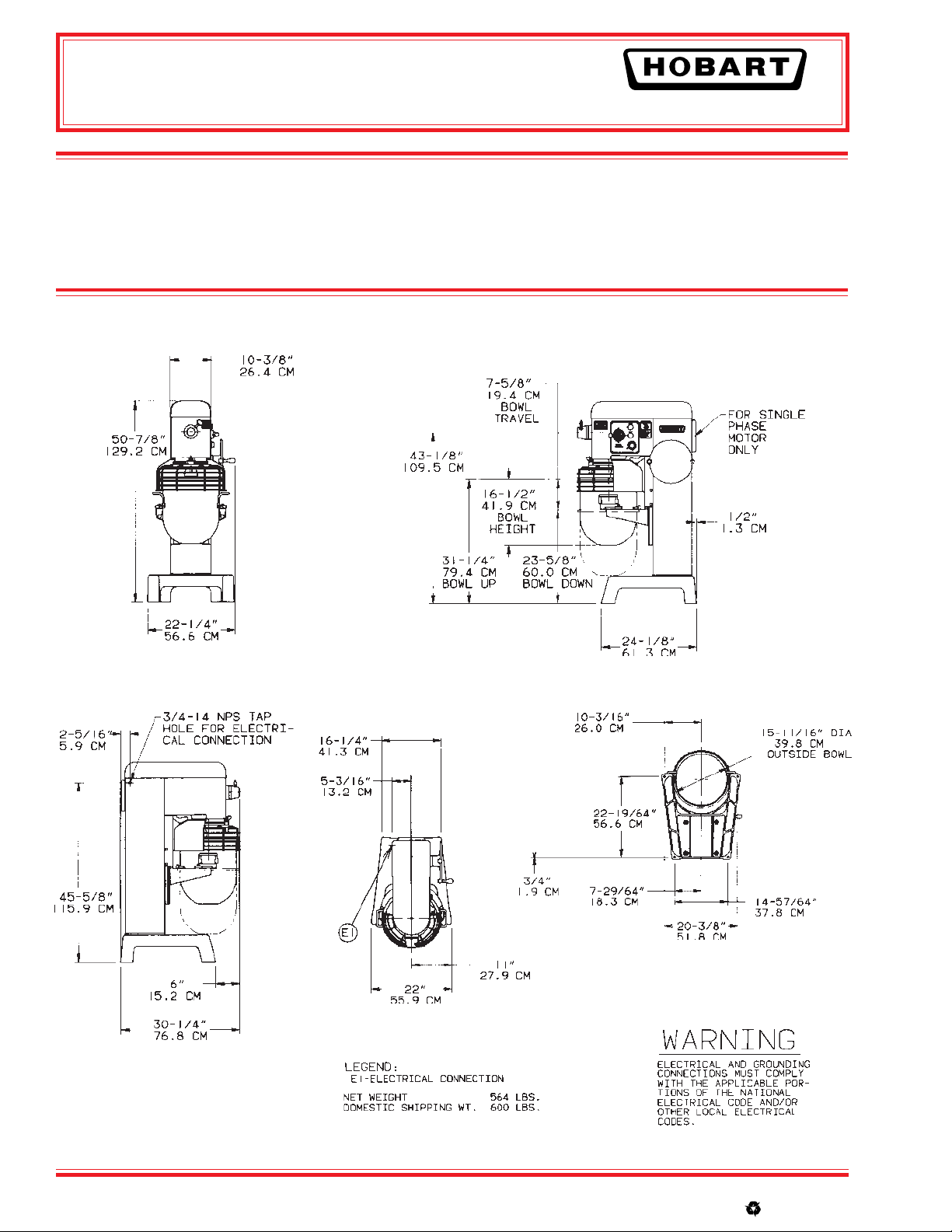
Specifications, Details and Dimensions on Inside and Back.
R
❑ Stainless Steel Bowl
❑ “B” Flat Beater
❑ “C” Wing Whip
❑ “D” Wire Whip
❑ “ED” Dough Hook
❑ “P” Pastry Knife
❑ “I” Heavy Duty Wire Whip
❑ Bowl Truck
❑ Bowl Scraper
❑ 20 Quart Accessories
❑ Ingredient Chute
❑ 9" Vegetable Slicer
❑ Meat Chopper Attachment
D340 MIXER
F-8426 – D340 Mixer Page 1 of 4
Page 4
D340
D340 Mixer Technical Manual Page 4 of 67
MIXER
SOLUTIONS/BENEFITS
11⁄2 H.P. Hobart Designed Motor
Durability
■ Heavy-duty to meet the most demanding
operations
15-Minute Electric Timer
Convenience, Ease of Use, Consistency
■ Supports recipe mixing times
■ Simplifies operation
■ Provides accurate results and eliminates
overmixing
Three Fixed Speeds
Flexibility, Reliability, Consistency
■ For incorporating, blending, mixing ingredients
■ Supports consistent results and thorough
mixing
Bowl Guard
Protection
■ Safety interlock prevents operation when front
portion of guard is out of position
Gear-Driven Transmission
Durability, Reliability
■ Ensures consistent performance and minimum
downtime with positive drive under heady loads
Hobart Attachments
Durability, Flexibility
■ Hobart manufactured accessories are designed
for long-term usage under heavy-duty
conditions
■ Large array of attachments provides multiple
uses for recipe and product processing
701 S Ridge Avenue, Troy, OH 45374
1-888-4HOBART • www.hobartcorp.com
D340 MIXER CAPACITY CHART
Recommended Maximum Capacities - dough capacities based
on 70°F water and 12% flour moisture
AGITATORS
PRODUCT SUITABLE FOR D340
CAPACITY OF BOWL (QTS. LIQUID) 30
Egg Whites D 13⁄4 qts.
Mashed Potatoes B & C 30 lbs.
Mayonnaise (Qts. of Oil) B or C or D 13 qts.
Meringue (Qts. of Water) D 11⁄2 qts.
Waffle or Hot Cake Batter B 16 qts.
Whipped Cream D or C 9 qts.
Cake, Angel Food
(8-10 oz. cake) C or I 30
Cake, Box or Slab B or C 40 lbs.
Cake, Cup B or C 45 dz.
Cake, Layer B or C 45 lbs.
Cake, Pound B 40 lbs.
Cake, Short (Sponge) C or I 25 lbs.
Cake, Sponge C or I 40 lbs.
Cookies, Sugar B 30 lbs.
Dough, Bread or Roll (Lt.-Med.)
60% AR § ED 45 lbs.
Dough, Heavy Bread 55% AR § ED 35 lbs.
Dough Pie B & P 35 lbs.
Dough, Thin Pizza 40% AR
(max. mix time 5 min.) §† ED 25 lbs.
Dough, Med. Pizza 50% AR §† ED 32 lbs.
Dough, Thick Pizza 60% AR §† ED 45 lbs.
Dough, Raised Donut 65% AR ED 25 lbs.*
Dough, Whole Wheat 70% AR ED 45 lbs.
Eggs & Sugar for Sponge Cake B & C or I 18 lbs.
Icing, Fondant B 25 lbs.
Icing, Marshmallow C or I 41⁄2 lbs.
Shortening & Sugar, Creamed B 35 lbs.
Pasta, Basic Egg Noodle
(max. mix time 5 min.) ED 15 lbs.
NOTE: %AR (% Absorption Ratio) - Water weight divided by
flour weight. Capacity depends on moisture content of dough.
Above capacities based on 12% flour moisture at 70°F water
temperature.
■■
1st Speed
* 2nd Speed
§ If high gluten flour is used, reduce above dough batch size
by 10%.
† 2nd speed should never be used on 50% AR or lower
products.
USE OF ICE REQUIRES A REDUCTION IN BATCH SIZE.
1 gallon of water weighs 8.33 lbs.
NOTE: Attachment hub should not be used while mixing.
OPERATION
■■
■■
■■
■■
■■
■■
Page 2 of 4 F-8426 – D340 Mixer
Page 5
D340
D340 Mixer Technical Manual Page 5 of 67
701 S Ridge Avenue, Troy, OH 45374
1-888-4HOBART • www.hobartcorp.com
SPECIFICATIONS
MOTOR:
11⁄2 H.P., Hobart designed, permanently lubricated
ball bearings, totally enclosed, fan-cooled.
Single-phase is capacitor-start, capacitor-run type.
Three-phase is squirrel cage, induction-run type.
ELECTRICAL:
120/60/1, 208/60/1, 240/60/1, 208/60/3, 240/60/3,
and 480/60/3 – U L Listed. Also available in 380/50/3
and 415/50/3 – not submitted for U L Listing.
CONTROLS:
Magnetic contactor with bimetallic thermal overload
protection internally mounted. “Start-Stop” pushbuttons protected by rubber caps. A 15-minute
electric timer is standard.
TRANSMISSION:
Gear-driven. Gears are constant mesh heat-treated
alloy steel. Anti-friction ball or roller bearings.
A hardened steel worm and alloy bronze worm gear
transmit power from motor to transmission. Grease
lubricated.
SPEEDS:
Three positive speeds - Low, Intermediate, and High.
Agitator Attachment
(RPM) (RPM)
MIXER
FINISH:
Metallic Gray Hybrid Powder Coat finish. Top
Charcoal Gray, Polyurethane Enamel.
STANDARD EQUIPMENT:
Consists of the mixer unit with one (1) 40-quart
stainless steel bowl, one (1) “B” flat beater, one (1)
“D” wire whip, one (1) stainless steel “ED” dough
hook and stainless steel bowl guard.
ATTACHMENT HUB:
Equipped with front-mounted Hobart standard #12
taper attachment hub, and any #12 size attachments
may be used.
NOTE: Use of attachment hub during mixing operation may result in a negative impact on performance
and longevity of mixer.
ATTACHMENTS AND ACCESSORIES:
The following are available at extra cost:
Stainless Steel Bowl
“B” Flat Beater
“C” Wing Whip
“D” Wire Whip
“ED” Dough Hook
“P” Pastry Knife
“I” Heavy Duty Wire
Whip
Bowl Truck
Bowl Scraper
20 Quart Accessories
Ingredient Chute
9" Vegetable Slicer
Meat Chopper Attachment
Low 96 56
Intermediate 179 104
High 319 185
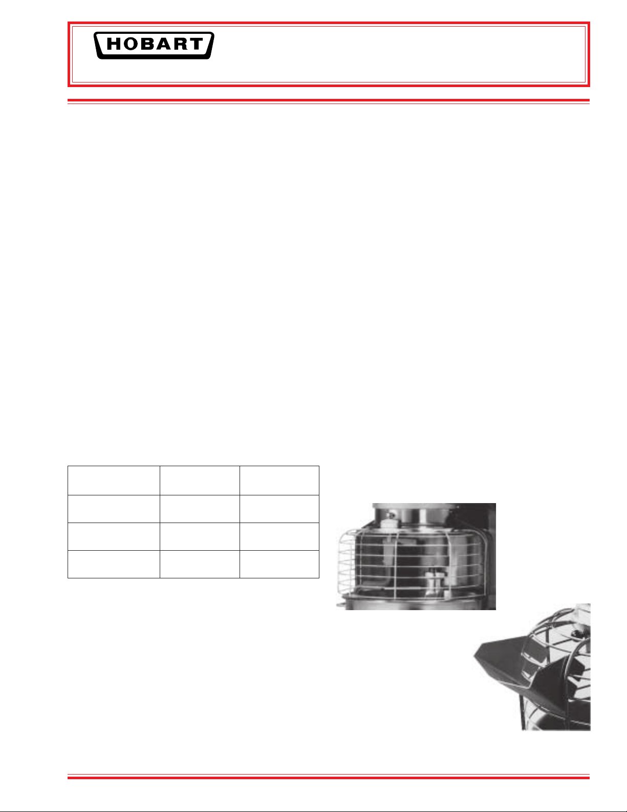
BOWL GUARD:
Heavy-duty stainless steel wire front and solid
stainless steel rear portion. Front portion of guard
rotates easily to add ingredients and install or
remove agitator. It detaches in seconds for cleaning
in dishwasher or sink. Rear portion of guard can be
quickly cleaned in position. Guard must be in closed
position before mixer will operate. The bowl support
lock prevents the bowl from being lowered while
mixer is running. Bowl support interlock provides
further protection.
BOWL LIFT:
Hand crank operated, self-locking in any position.
F-8426 – D340 Mixer Page 3 of 4
Hobart Bowl
Scraper
Hobart Ingredient
Chute
LISTED BY: Underwriters Laboratories, Inc. and NSF International.
Certified by the Baking Industry Sanitation Standard Committee.
Page 6
D340
D340 Mixer Technical Manual Page 6 of 67
MIXER
SPECIFICATIONS
ELECTRICAL SPECIFICATIONS: 120/60/1,
208/60/1, 240/60/1, 208/60/3 and 480/60/3 –
U L Listed. Also available in 380/50/3 and 415/50/3
– not submitted for U L Listing.
DETAILS AND DIMENSIONS
701 S Ridge Avenue, Troy, OH 45374
1-888-4HOBART • www.hobartcorp.com
WEIGHT: 575 lbs. net; 600 lbs. domestic shipping.
WARRANTY: Unit has full one-year warranty on
parts, labor and mileage against manufacturer’s
defects. Service contracts are available.
As continued product improvement is a policy of Hobart, specifications are subject to change without notice.
Page 4 of 4 F-8426 – D340 Mixer
F-8426 (REV. 2/04) LITHO IN U.S.A. (H-01)
Printed On Recycled Paper
Page 7

D340 MIXERS
D340 Mixer Technical Manual Page 7 of 67
D340 ML - 1 3425 4
I
N
S
T
D340 MIXER
R
U
C
T
I
O
N
S
D340 W/Electronic Timer ML - 1 3 425 6
701 S. RIDGE AVENUE
TROY, OHIO 45374-0001
937 332-3000
www.hobartcorp.com
F34926 (June 2005)
Page 8
D340 Mixer Technical Manual Page 8 of 67
MODEL D340 MIXER
– 2 –© HOBART 2005
Page 9

2345678901234567890123456789012123456789
0
0
0
0
0
0
0
0
0
0
0
0
0
0
0
0
0
0
0
0
0
0
0
0
0
0
0
0
0
0
0
0
0
D340 Mixer Technical Manual Page 9 of 67
2345678901234567890123456789012123456789
2345678901234567890123456789012123456789
2345678901234567890123456789012123456789
2345678901234567890123456789012123456789
2345678901234567890123456789012123456789
2345678901234567890123456789012123456789
2345678901234567890123456789012123456789
2345678901234567890123456789012123456789
2345678901234567890123456789012123456789
2345678901234567890123456789012123456789
2345678901234567890123456789012123456789
2345678901234567890123456789012123456789
2345678901234567890123456789012123456789
2345678901234567890123456789012123456789
2345678901234567890123456789012123456789
2345678901234567890123456789012123456789
2345678901234567890123456789012123456789
2345678901234567890123456789012123456789
2345678901234567890123456789012123456789
2345678901234567890123456789012123456789
2345678901234567890123456789012123456789
2345678901234567890123456789012123456789
2345678901234567890123456789012123456789
2345678901234567890123456789012123456789
2345678901234567890123456789012123456789
2345678901234567890123456789012123456789
2345678901234567890123456789012123456789
2345678901234567890123456789012123456789
2345678901234567890123456789012123456789
2345678901234567890123456789012123456789
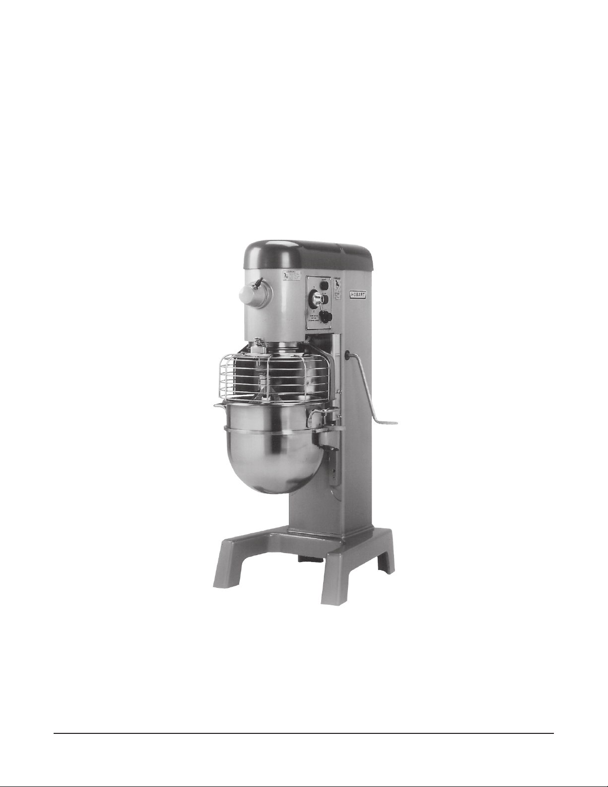
The D340 Mixer is a medium-duty mixer which develops 11/2 horsepower and features a timer, thermal
2345678901234567890123456789012123456789
2345678901234567890123456789012123456789
overload protection and a #12 Attachment Hub as standard equipment. A variety of agitators are
Installation, Operation and Care of
MODEL D340 MIXERS
SAVE THESE INSTRUCTIONS
GENERAL
available for use on either the standard 40-quart bowl or the optional 30-quart bowl. A special 20-quart
bowl and agitators are available options.
Programmable Timer Controller is optional on D340 models.
A variety of attachments and accessories are available for all mixers. These are described in a
separate
Use and Applications Handbook,
which is furnished with each mixer.
UNPACKING
Immediately after unpacking the mixer, check for possible shipping damage. If this machine is found
to be damaged, save the packaging material and contact the carrier within 15 days of delivery.
Prior to installation, test the electrical service to assure that it agrees with the specifications on the
machine data plate.
LOCATION
Place the mixer in its operating location. There should be adequate space around the mixer for the user
to operate the controls and to install and remove bowls. The area above the mixer should allow the top
cover to be removed for routine maintenance and servicing.
Holes are provided in the base for permanent bolting to the floor, although this is not necessary in normal
installations. Four plastic plugs are supplied with the mixer to plug these holes if they are not used.
INSTALLATION
– 3 –
Page 10
ELECTRICAL CONNECTION
D340 Mixer Technical Manual Page 10 of 67
WARNING: ELECTRICAL AND GROUNDING CONNECTION MUST COMPLY WITH THE
APPLICABLE PORTION OF THE NATIONAL ELECTRICAL CODE AND/OR OTHER LOCAL
ELECTRICAL CODES.
WARNING: DISCONNECT THE ELECTRICAL POWER TO THE MACHINE AND FOLLOW
LOCKOUT / TAGOUT PROCEDURES.
C06
reppoC
erIW
eziS
tiucriC
eziS
)spmA(
rekaerBtiucriC
)spmA(
sledoM hP/zH/stloV
detaR
spmA
tiucriC
eziS
)spmA(
esuF
eziS
)spmA(
043D1/06/0214.21020221020221
043D1/06/8020.8510141020221
043D1/06/0422.6510141515141
043D3/06/8028.351641516 41
043D3/06/0424.351641516 41
043D3/06/0847.151341516 41
C06
eriWreppoC
eziS
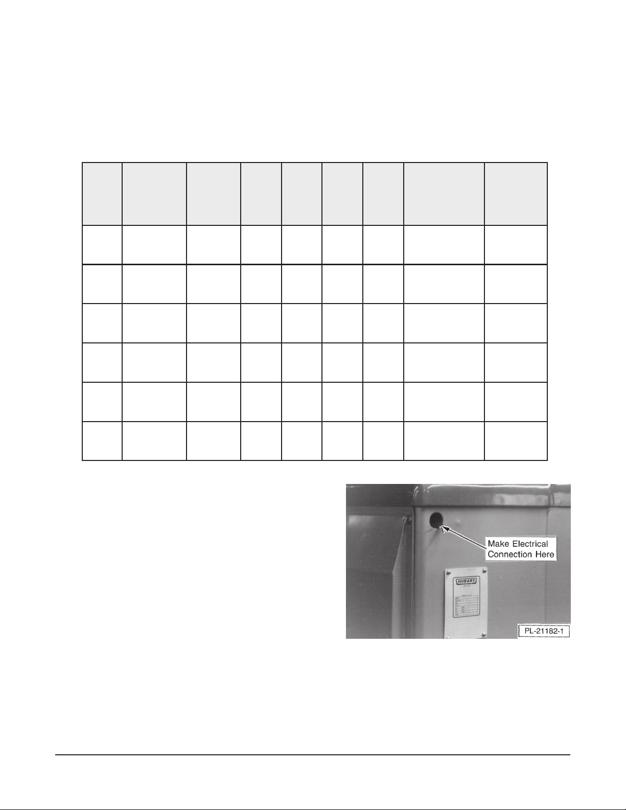
A hole for
1
/2 trade size conduit is located at the top of the
pedestal (Fig. 1). Make electrical connections per the
wiring diagram located on the inside of the top cover.
Check Rotation (Three-Phase Machines Only)
Three-phase machines must be connected so the
planetary rotates in the direction of the arrow on the Drip
Cup. To check rotation:
1. Set the Gear Shift Lever on 1.
2. Apply power to the mixer, set the
Electromechanical Timer on hold; or, if equipped
with a Programmable Timer Controller, set it on
Fig. 1
[-- : --]. With the Bowl Support all the way up,
momentarily run the machine by pushing the START and then STOP buttons.
3. If rotation is incorrect, disconnect electrical power supply and interchange any two of the
incoming power supply leads.
– 4 –
Page 11
OPERATION
D340 Mixer Technical Manual Page 11 of 67
WARNING: MOVING BEATER IN BOWL. KEEP HANDS, CLOTHING AND UTENSILS OUT
WHILE IN OPERATION. DO NOT USE WITHOUT INTERLOCKED GUARD.
Every D340 mixer is equipped with either an Electromechanical Timer Control (described at the bottom
of this page) or a Programmable Timer Controller (described on page 6). Also, become familiar with the
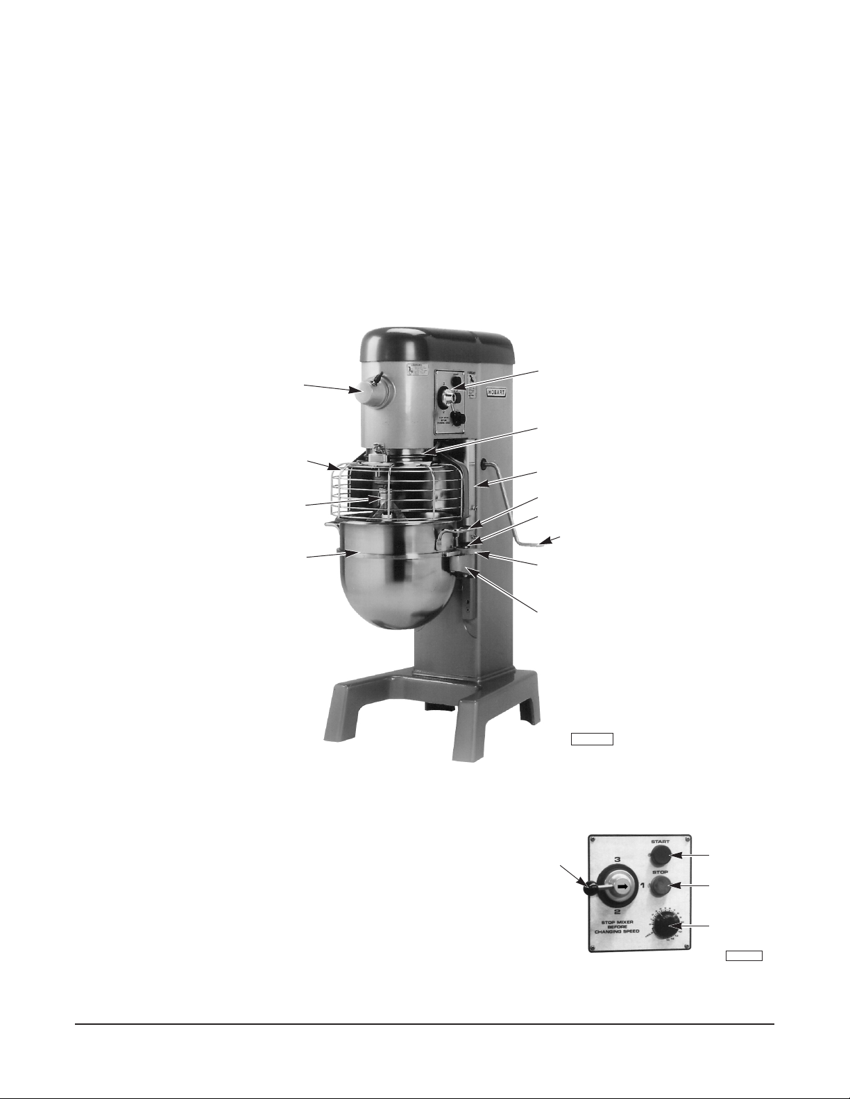
other operating parts (Fig. 2) and their functions, which are referenced throughout the Operation
section.
The Bowl Guard must be in the Front-Center Position or the mixer will not operate (see page 10).
If the Bowl Support is not all the way up, the mixer will not operate unless the START button is held in.
Controls
Attachment Hub
Drip Cup
Bowl Guard
(Wire Cage)
Agitator
Bowl
Apron
Bowl Handle
Alignment Pin
Bowl Lift Handle
Bowl Clamp
Bowl Support
PL-40174-1
Fig. 2
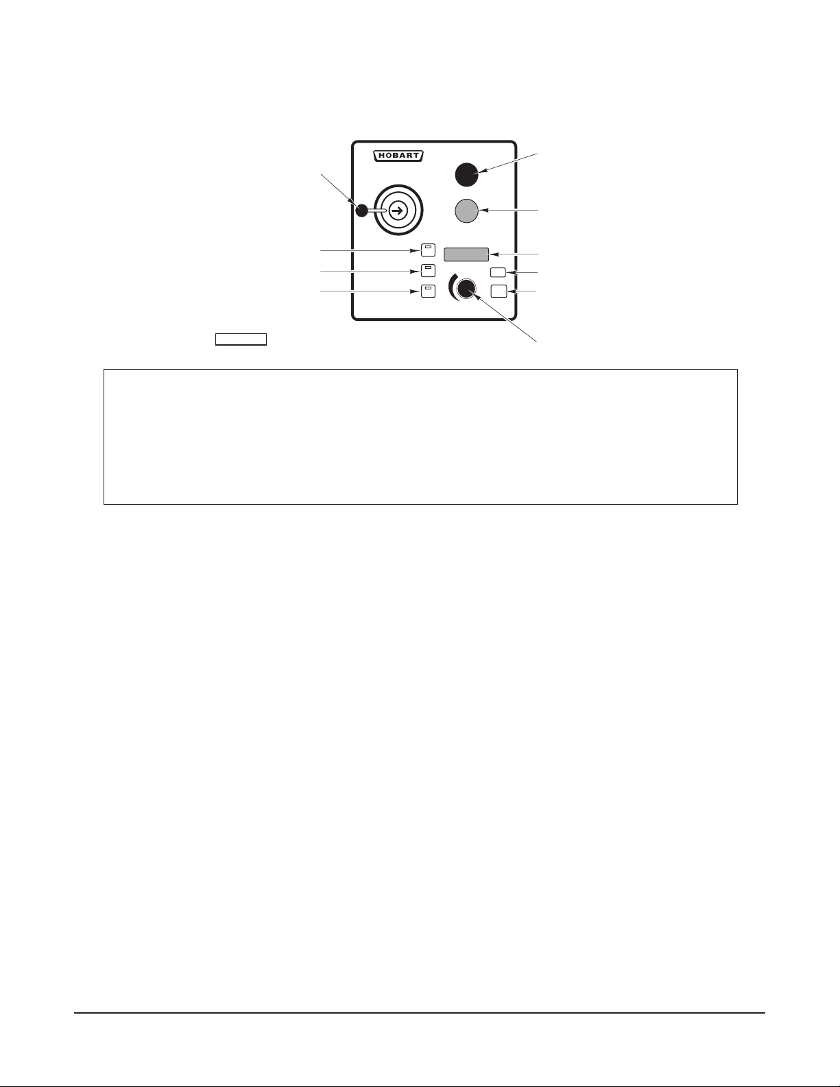
ELECTROMECHANICAL TIMER CONTROLS (When Equipped, Fig. 3)
The START button is used to start the mixer.
The STOP button is used to stop the mixer.
Gear Shift Lever
The TIMER is used in conjunction with the START
button for timed mixing operations and will stop the
mixer when a preset time has elapsed.
Non-timed Mixing
Fig. 3
Set the timer on hold and use the START and STOP buttons to operate the mixer.
Start Button
Stop Button
Timer
PL-40142-1
– 5 –
Page 12
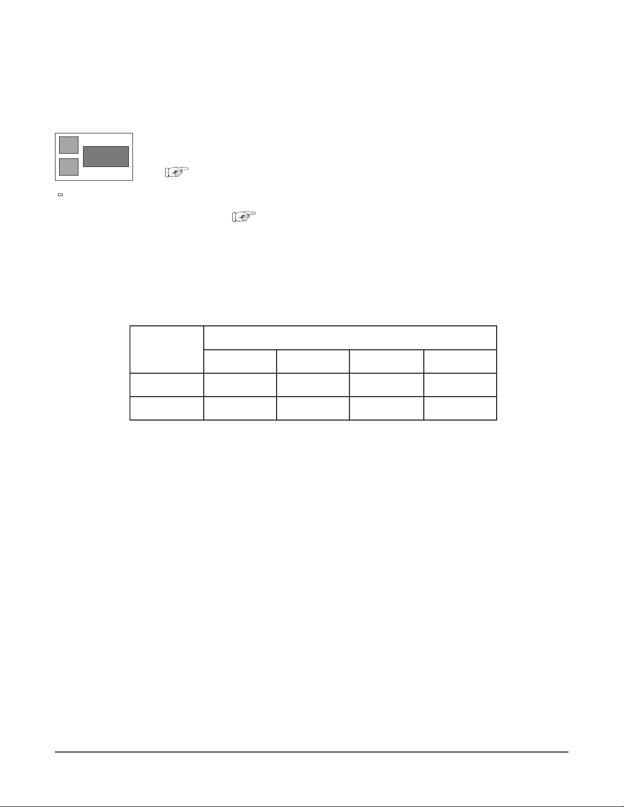
PROGRAMMABLE TIMER CONTROLLER (When Equipped)
D340 Mixer Technical Manual Page 12 of 67
At idle, the TIME DISPLAY [--:--] shows that no time has been set (Fig. 4).
Timer Keys Programming Function (if the mixer is not mixing)
P1 Contains up to four preset times. Displays each preset time sequentially.
P2 Contains up to four additional preset times. Displays each preset time sequentially.
TIME Knob Turn the TIME knob until the desired time is shown on the TIME DISPLAY.
SAVE Replaces the preset time with the indicated time.
CLEAR Returns to idle from a programming function.
Continuous Mixing
GEAR SHIFT LEVER
P1 KEY
P2 KEY
M/C INDICATOR
PL-56563
3
2
STOP MIXER
BEFORE
CHANGING SPEEDS
Fig. 4
START
STOP
1
TIMER CONTROLLER
P1
123 4
P2
TIME
M/C
SAVE
CLEAR
START BUTTON
STOP BUTTON
TIME DISPLAY
SAVE KEY
CLEAR KEY
KNOB
START and STOP buttons control mixing operation.
Beginning from the idle display [-- :--], press START to begin mixing. The M/C Indicator will be lit,
and the total mixing time will be indicated (minutes and seconds).
Press STOP when mixing is done. The M/C Indicator light goes off and the idle display [-- :--]
returns.
Set Mixing Time (Using TIME Knob)
Beginning from the idle display [-- :--], turn the TIME knob to set the mixing time. The M/C Indicator
will be lit.
START and STOP buttons control mixing operation.
Press START to begin mixing. The timer will count down from the set time to [00 : 00].
If STOP is pressed, both mixing and timer countdown will be interrupted. After pressing STOP,
press START to resume both mixing and timer countdown; or, press CLEAR to return to the idle
display.
When the timer reaches [00 : 00], the mixer will stop and the M/C Indicator will be lit. A
tone will sound for 2 seconds and the idle display [-- :--] will return.
– 6 –
Page 13

Set Mixing Time (Preset Keys P1 or P2)
D340 Mixer Technical Manual Page 13 of 67
Each preset key has four time settings. The indicator lights above the number 1, 2, 3 or 4 and the P1
or P2 indicator light identify which preset time is being displayed. The chart below shows the default
settings. The next page shows how to revise these preset times. The TIME Knob can be used to adjust
the mixing time if it is turned prior to pressing START.
-
P1
01:00
-
- - - -
P2
1 2 3 4
Indicators above P1
and 1 indicate the
first preset time
contained in P1.
Beginning from the idle display [-- :--], press P1 or P2 to display the #1 preset mixing
time. (Pressing P1 or P2 again will display the next preset time, etc.)
The TIME knob can adjust the time.
START and STOP buttons control mixing operation.
Press START to begin mixing. The timer will count down from the set time to [00 :
00].
If STOP is pressed, both mixing and timer countdown will be interrupted. After
pressing STOP, press START to resume both mixing and timer countdown; or press
CLEAR to return to the idle display.
When the mixer is stopped, you can perform the following tasks: add ingredients,
change speed, reset the timer, continue mixing or unload.
When the timer reaches [00 : 00], the mixer stops. A tone sounds for 2 seconds and
the next preset mixing time displays. When the last preset time reaches [00 : 00], the
P1 or P2 indicator light is lit and the idle display [-- : --] returns. Repeat from
to complete four preset times.
The timer reverts to the factory-programmed preset times after any power interruption.
FACTORY-PROGRAMMED PRESET TIMES
rotacidnI
yeKteserP
12 3 4
1P00:1000:2000:0100:00
2P00:2000:1000:5000:30
– 7 –
Page 14
Revise Preset Mixing Times (Preset Keys P1 or P2)
D340 Mixer Technical Manual Page 14 of 67
Each preset key has four preset time settings. The indicator lights above the number 1, 2, 3 or 4 and
the P1 or P2 indicator light identify which preset time is being displayed.
-
P1
01:00
-
- - - -
P2
1 2 3 4
Indicators above P1
and 1 indicate the
first preset time
contained in P1.
Beginning from the idle display [-- :--], press P1 or P2 to display the #1 preset
mixing time. (Pressing P1 or P2 again will display the next preset time, etc.)
Turn the TIME knob to change the time for the indicated preset.
Press SAVE to retain the revised time and move to the next preset time.
Repeat from
for each preset time (1, 2, 3 and 4 contained in P1 or P2).
Press CLEAR to retain the saved times and return to the idle display [-- : --].
The timer reverts to the factory-programmed preset times after any power interruption.
FACTORY PROGRAMMED PRESET TIMES
rotacidnI
yeKteserP
12 3 4
1P00:1000:2000:0100:00
2P00:2000:1000:5000:30
CHANGING SPEEDS
The Gear Shift Lever is used to change speeds. Always stop the mixer before changing speeds.
1. Push the STOP button.
2. Move the Gear Shift Lever to the desired speed.
3. Push the START button to restart the mixer.
NOTE: If you do not stop the mixer to change speeds, it will automatically shut itself off and you will
have to restart it after changing speeds.
Mixer Speeds
Speed 1 (Low) — This speed is for heavy mixtures such as bread dough, heavy batters and potatoes.
Speed 2 (Medium) — This speed is for light dough (which must rise quickly), cake batters, mashing
potatoes and some whipping operations.
Speed 3 (High) — This is a fast speed for light work, such as whipping cream, beating eggs and mixing
thin batters.
– 8 –
Page 15

BOWL LIFT
D340 Mixer Technical Manual Page 15 of 67
D340 models are equipped with a Bowl Lift Handle (see Fig. 2). Mixers equipped with Bowl Lift Handle
must be turned off to lower the bowl.
• Raise the bowl by rotating the lift handle
• Lower the bowl by rotating the lift handle
downward.
upward
.
MIXING
This section explains operation of the mixer and how to install bowls, agitators and attachments. A
separate
Use and Applications Handbook,
provided with the mixer, contains information on mixing
procedures and outlines specific uses for agitators, attachments and accessories.
Bowl
New mixer bowls and agitators (beaters, whips and dough arms) should be thoroughly washed with hot
water and a mild soap solution, rinsed with either a mild soda or vinegar solution, and thoroughly rinsed
with clear water before being used. This cleaning procedure should also be followed for bowls and
agitators before whipping egg whites or whole eggs.
The bowl must be installed before the agitator is installed.
To install the bowl, fully lower the Bowl Support (Fig. 2). Position the bowl so the alignment bracket on
the back of the bowl is in the bowl retainer on the Bowl Support and the alignment pins on the front of
the Bowl Support fit in the holes in the bowl. Lock the bowl in place by rotating the Bowl Clamps (Fig.
2) over the ears of the bowl.
Agitator
To install an agitator, the bowl must be installed and fully lowered. Place the agitator in the bowl, push
the agitator up on the agitator shaft and turn the agitator
clockwise
to seat the shaft pin in the slot of the
agitator shank.
To Raise the Bowl While Mixing
To raise the bowl while the agitator is mixing the product (when required by recipe or when using the
bowl scraper attachment):
1. Load ingredients.
2. Close the wire cage assembly.
3. Select low speed.
4. To begin mixing, press and hold the START button; then raise the bowl.
– 9 –
Page 16
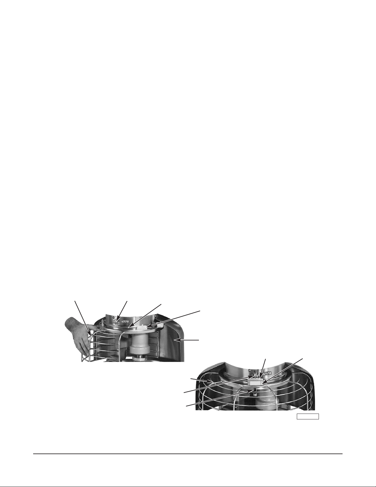
BOWL GUARD
D340 Mixer Technical Manual Page 16 of 67
The Wire Cage Assembly can be rotated out of the way to add ingredients or to access the bowl and
agitator.
Rotate the Wire Cage Assembly
Push the Latch in to release the Centering Pin from the Centering Ramp. Note how the grooves on the
nylon retainers allow the Wire Cage to ride around the circular Ridge on the Planetary Drip Cup. The
Wire Cage can rotate 360° left or right. When the Wire Cage returns to the Front-Center Position, the
Centering Pin is captured and held by the Centering Ramp, restricting rotation of the Wire Cage until
the Latch is pressed again.
The Wire Cage must be in the Front-Center Position for the mixer to operate.
Remove Wire Cage Assembly
Lower the bowl. Rotate the Wire Cage to the rear. Remove both agitator and bowl. Return the Wire Cage
to the front.
While holding the Wire Cage securely with both hands, use your thumb to push down on the Black
Release Knob. Lower and remove the Wire Cage. Wash it in a sink, rinse with clear water and dry with
a clean cloth.
The stainless steel Splash Guard can be wiped off or washed easily with a cloth or sponge and warm,
soapy water. Rinse with clear water and dry with a clean cloth.
Reinstall Wire Cage Assembly
Hold the Wire Cage so its top ring is positioned around the Drip Cup with the grooves in both nylon Rear
Retainers straddling the Ridge on the Drip Cup. Push in the Front-Center Retainer until it stays in and
its grooves straddle the Ridge on the Drip Cup. The Wire Cage is properly assembled when all three
Retainers straddle the Ridge on the Drip Cup in the three opposed locations.
Rotate the Wire Cage to the rear to install or remove the agitator and bowl or to add ingredients.
Return the Wire Cage to the Front-Center Position to operate the mixer.
Wire Cage Rotated Left
Latch
Ridge On Drip Cup
Wire Cage Front-Center Position
Centering Pin
Rear Retainer
Splash Guard
Centering Ramp
Front-Center
Retainer
Black Release Knob
PL-40071-1
Fig. 5
– 10 –
Page 17

ATTACHMENTS
D340 Mixer Technical Manual Page 17 of 67
To install an attachment, loosen the Attachment Hub thumb screw (Fig. 2) and remove the plug. Insert
the attachment into the Attachment Hub, making certain that the square shank of the attachment is in
the square driver of the mixer. Secure the attachment by tightening the thumb screw.
Move the Gear Shift Lever to the desired speed. With the Bowl Support all the way up and the Wire Cage
in the Front-Center Position (Fig. 5), start the mixer to operate the attachment.
The meat and food chopper attachment should be operated in second or third speed. If material in the
cylinder stalls the mixer, push the STOP button at once. Do not attempt to restart the mixer in a lower
speed; remove the adjusting ring, knife, plate and worm and clear any obstruction.
Note: This attachment must not be used to chop bread crumbs.
Bowl Scraper Attachment
The Mixer bowl scraper attachment (when ordered) is provided with a separate instruction manual
covering its installation, operation, use and care.
CLEANING
WARNING: DISCONNECT THE ELECTRICAL POWER TO THE MACHINE AND FOLLOW
LOCKOUT / TAGOUT PROCEDURES.
A flat scraper and a brush are furnished to aid in cleaning bowls and agitators.
The mixer should be thoroughly cleaned daily. Do not use a hose to clean the mixer; wash with a clean,
damp cloth. The base allows ample room for cleaning under the mixer. The apron may be removed by
loosening the thumb screws. Behind this apron is an access cover which may be removed for cleaning.
The Drip Cup-Splash Guard Assembly (Fig. 5) should be removed periodically and wiped clean.
MAINTENANCE
WARNING: DISCONNECT THE ELECTRICAL POWER TO THE MACHINE AND FOLLOW
LOCKOUT / TAGOUT PROCEDURES.
LUBRICATION
Bowl Clamps
The bowl clamp area of the bowl support should be lubricated twice a year. Lightly coat with Lubriplate
630AA (supplied).
– 11 –
Page 18
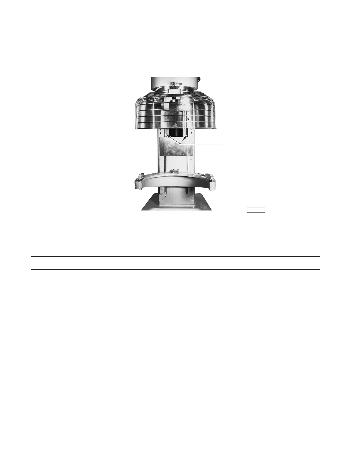
BOWL LIFT SLIDE-WAYS
D340 Mixer Technical Manual Page 18 of 67
The Slideways (Fig. 8) should be lubricated once each month. Remove the apron (secured by four
thumb screws) from the front of the pedestal. Lightly coat both Slideways with Lubriplate 630AA
(supplied). Replace the apron and thumbscrews.
Bowl Lift Slideways
Fig. 8
TROUBLESHOOTING
SYMPTOMS POSSIBLE CAUSES
Mixer will not start.
1. Gear Shift Lever between gears (not fully
engaged).
2. Circuit protector in open position — check fuse
or disconnect switch.
3. Bowl not all the way up.
4. Wire Cage Assembly is not in the Front-Center
Position.
5. Mixer or attachment overloaded.
PL-40172-1
SERVICE
If service is needed on this equipment, contact your local Hobart Service Office.
FORM 34926 (June 2005) PRINTED IN U.S.A.
Page 19
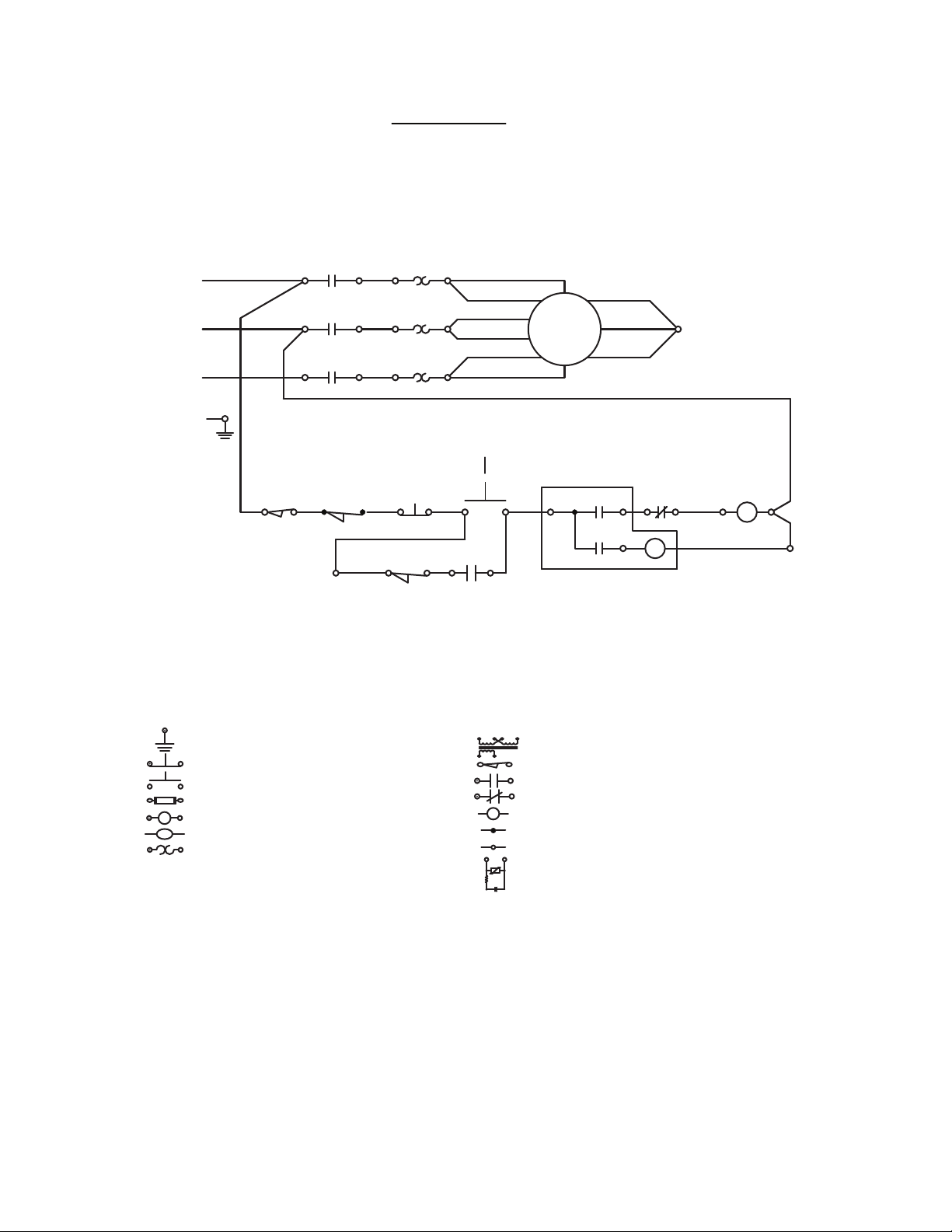
WARNING
D340 Mixer Technical Manual Page 19 of 67
ELECTRICAL AND GROUNDING CONNECTIONS
MUST COMPLY WITH THE APPLICABLE
PORTIONS OF THE NATIONAL ELECTRICAL
CODE AND/OR OTHER LOCAL ELECTRICAL CODES.
L1
L2
L3
GND
L1
L2 L2
L3
LS
CNC
CON
CON
CON
2LS
GUARD
SPLICE
OL
L1 T1
T1
OL
T2
T3
L3
3LS
HEIGHT
T2
OL
T3
1PB
STOP
CNC
2PB START
*
NC
NO
C
CON
SYMBOL DEFINITIONS
T1
T7
T2
T8
T3
T9
NO
MIXER
MOTOR
12
C
TIMER
T4
T5
T6
OL
CNC
3
C1
CON
C3
SPLICE
GND GROUND
PB PUSH BUTTON-STOP (N.C.)
PB PUSH BUTTON-START (N.O.)
FUSE
FU
CONTACTOR COILCON
TIMERTMR
OL OVERLOAD HEATER ELEMENT
DERRIVED FROM F-18763E
T TRANSFORMER
LS
LIMIT SWITCH
CONTACT-NORMALLY OPEN (N.O.)
CONTACT-NORMALLY CLOSED (N.C.)
MOTOR
INSEPARABLE CONNECTION
SEPARABLE CONNECTION
RC
SNUBBER ASSY
ELECTRICAL DIAGRAM
D-340 MIXER
208V - 60HZ - 3PH
AI 2594
Page 20
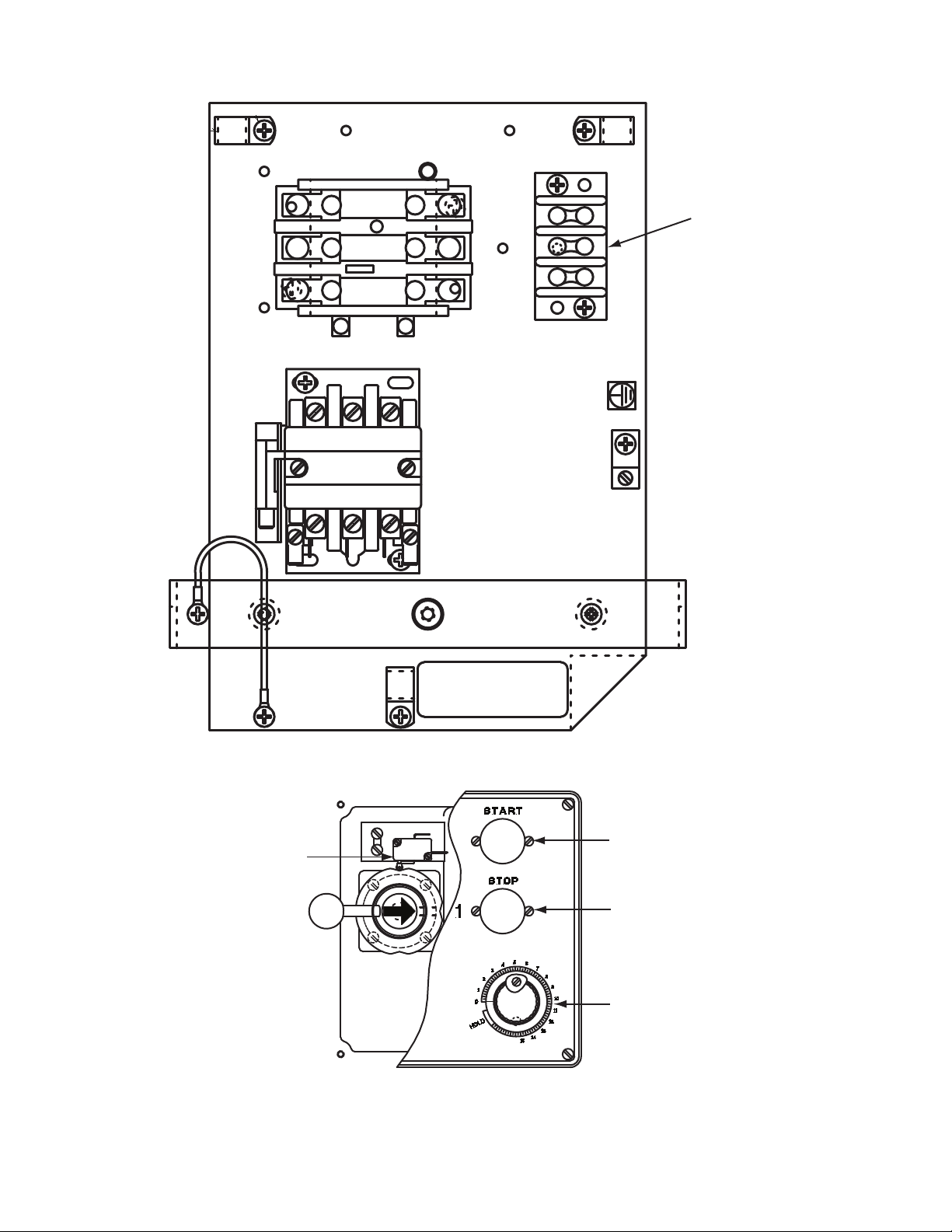
OL
D340 Mixer Technical Manual Page 20 of 67
OL
OL
T2T3
T1
CON
L3 L2 L1
MOTOR
CONNECTIONS
LS
FOR SUPPLY CONNECTION USE WIRES
SUITABLE FOR AT LEAST 90°C, OR
EQUIVALENT.
NOTE
2PB
1PB
TMR
COMPONENT LAYOUT
AI 2595
Page 21

CATALOG OF
D340 Mixer Technical Manual Page 21 of 67
REPLACEMENT
PARTS
MODEL D340 MIXER
(INCLUDES MOTOR PARTS)
D340 ML-134254
D340C ML-134257
PRIOR MLS COVERED IN THIS CATALOG
D340 ML-134185
D340C ML-134188
D340 W/O Brake ML-104483
D340 W/Brake ML-104484
D340C ML-134118
A product of HOBART 701 S. RIDGE AVENUE TROY, OHIO 45374-0001
FORM 19154 Rev. C (August 2005)
Page 22

MODEL D340 MIXER REPLACEMENT PARTS
D340 Mixer Technical Manual Page 22 of 67
F-19154 Rev. C (August 2005)
- 2 -
© HOBART
Page 23

MODEL D340 MIXER REPLACEMENT PARTS
D340 Mixer Technical Manual Page 23 of 67
Table of Contents
5 TIMER CONTROL AND SWITCH UNIT
7 ELECTRICAL COMPONENT PANEL – 1 PHASE
9 ELECTRICAL COMPONENT PANEL – 3 PHASE
11 BASE AND COLUMN
(ML-104483, ML-104484, & ML-134118)
13 BASE AND COLUMN
(ML-134185, ML-134188, ML-134254, & ML-134257)
15 BOWL SUPPORT
(ML-104483, ML-104484, & ML-134118)
17 BOWL SUPPORT AND LIFT UNIT
(ML-134185, ML-134188, ML-134254, & ML-134257)
19 TRANSMISSION CASE
21 SHIFTER UNIT
22 MOTOR PARTS – 1 PHASE
(*NON GE MOTORS)
23 MOTOR PARTS – 1 PHASE
(GENERAL ELECTRIC)
24 MOTOR PARTS – 3 PHASE
(*NON GE MOTORS)
25 MOTOR PARTS – 3 PHASE
(GENERAL ELECTRIC)
27 TRANSMISSION
29 PLANETARY AND ATTACHMENT HUB
31 BOWL GUARD UNIT
(PREVIOUS CONSTRUCTION)
33 BOWL GUARD UNIT
(CURRENT CONSTRUCTION)
34 BRAKE UNIT
35 BOWL
36 AGITATORS
- 3 -
F-19154 Rev. C (August 2005)
Page 24

MODEL D340 MIXER REPLACEMENT PARTS
D340 Mixer Technical Manual Page 24 of 67
38
1-2
39-40
30-31-32
33
34
3-4
5
6
7-8
9
10-11
18-19
35
12 THRU 17
20-21
36
37
22
23-24-25
26
27
28-29
TIMER CONTROL AND SWITCH UNIT
PL-56934
F-19154 Rev. C (August 2005)
- 4 -
Page 25

MODEL D340 MIXER REPLACEMENT PARTS
D340 Mixer Technical Manual Page 25 of 67
TIMER CONTROL AND SWITCH UNIT
ILLUS. PART NO. NAME OF PART AM T.
PL-56934
1 00-271312 Plate – Switch & Timer (ML-104483, ML-104484, ML-134185, & ML-134254) ........................ 1
2 00-271312 Plate – Switch & Timer (ML-134118, ML-134188, & ML-134257)............................................. 1
3 SC-013-12 Mach. Screw 6-32 x 1/4 Slotted Flat Hd.
4 SC-128-67 Mach. Screw 6-32 x 1/4 Tx. Flat Hd. (SST) (ML-134118, ML-134188, & ML-134257) ..............4
5 00-087711-183-4 Switch – Push Button (N.O.) .....................................................................................................1
6 00-102467-00001 Cap – Push Button (Start) (Black) .............................................................................................. 1
7 00-087711-183-2 Switch – Push Button (N.C.) ...................................................................................................... 1
8 00-087711-183-3 Switch – Push Button (N.C.) (ML-104484) ................................................................................ 1
9 00-102467-00002 Cap – Push Button (Stop) (Red) ................................................................................................ 1
10 SC-121-89 Mach. Screw 6-32 x 1/4 Hex Flat Hd. (SST) (ML-134118, ML-134188, & ML-134257) ............ 2
11 SC-013-07 Mach. Screw 5-40 x 1/4 Slotted Flat Hd. .................................................................................... 2
12 00-291748 Knob – Timer .............................................................................................................................. 1
13 00-294650-004-1 Timer Assy. (115 V., 60 Hz.) ......................................................................................................1
14 00-294650-004-2 Timer Assy. (200/300 V., 60 Hz.) ............................................................................................... 1
15 00-294650-004-3 Timer Assy. (415 V., 50 Hz.) ......................................................................................................1
16 SC-013-07 Mach. Screw 5-40 x 1/4 Slotted Flat Hd. .................................................................................... 2
17 00-271313 Insulator – Timer .........................................................................................................................1
18 SD-024-01 Self-Tapping Screw 10-24 x 3/8 Slotted Pan Hd., Type TT ........................................................ 2
19 SD-037-59 Self-Tapping Screw 10-24 x 1/2 Hex Button Hd., Type F
20 00-087711-183-4 Switch – Push Button (N.O.) .....................................................................................................1
21 SC-053-38 Mach. Screw 6-32 x 1/4 Slotted Truss Hd. ................................................................................. 2
22 00-102467-00001 Cap – Push Button (Start) (Black).............................................................................................. 1
23 00-087711-183-2 Switch – Push Button (N.C.) ...................................................................................................... 1
24 00-087711-183-4 Switch – Push Button (N.C.) (ML-104484)................................................................................ 1
25 SC-053-38 Mach. Screw 6-32 x 1/4 Slotted Truss Hd. (SST) ...................................................................... 2
26 00-102467-00002 Cap – Push Button (Stop) (Red) ................................................................................................ 1
27 SD-024-01 Self-Tapping Screw 10-24 x 3/8 Slotted Pan Hd., Type TT ........................................................ 4
28 00-437775 Knob – Potentiometer ................................................................................................................. 1
29 00-437742 Seal – Shaft ................................................................................................................................ 1
30 00-438323-00001 Switch Plate & Keypad Assy. (120 VAC) .................................................................................. 1
31 00-439400-00001 Board Assy. (120 VAC) ............................................................................................................. 1
32 00-439400-00002 Board Assy. (240 VAC) ............................................................................................................. 1
33 NS-046-17 Stop Nut 4-40 Hex ...................................................................................................................... 2
34 00-438499 Buzzer Assy............................................................................................................................... 1
35 00-477670 Hasp Weldment (ML-134118, ML-134188, & ML-134257) ........................................................ 1
36 00-477667 Cover Assy. & Hinge (ML-134118, ML-134188, & ML-134257) ................................................ 1
37 SC-128-69 Mach. Screw 10-24 x 3/8 Tx. Button Hd. (SST) (ML-134118, ML-134188, & ML-134257) ....... 2
38 NS-032-01 Lock Nut 10-24 Hex (ML-134118, ML-134188, & ML-134257) ................................................ 2
39 SD-024-01 Self-Tapping Screw 10-24 x 3/8 Slotted Pan Hd., Type TT ........................................................ 2
40 SD-037-58 Self-Tapping Screw 10-24 x 3/8 Hex Button Hd., Type F
(ML-104483, ML-104484, ML-134185, & ML-134254) ..............................................................4
(ML-134118, ML-134188, & ML-134257)...................................................................................2
(ML-134118, ML-134188, & ML-134257)..................................................................................2
- 5 -
F-19154 Rev. C (August 2005)
Page 26

MODEL D340 MIXER REPLACEMENT PARTS
D340 Mixer Technical Manual Page 26 of 67
30
29
28
31
1
2-3 4 5 6
T2L2
T1
L1
22
21
18
17
7
8
11
12
9
10
13
14
15
1619232425-26-27 20
PL-55617
F-19154 Rev. C (August 2005)
ELECTRICAL COMPONENT PANEL – 1 PHASE
- 6 -
Page 27

MODEL D340 MIXER REPLACEMENT PARTS
D340 Mixer Technical Manual Page 27 of 67
ELECTRICAL COMPONENT PANEL – 1 PHASE
ILLUS. PART NO. NAME OF PART AM T.
PL-55617
1 00-274031 Bracket – Support (Component Panel) (Top Cover).................................................................. 1
2 00-087713-037-2 Contactor (115 V., 60 Hz., 1 Ph.) (30 Amp.) (2 Pole) ................................................................ 1
3 00-087713-037-1 Contactor (208/240 V., 60 Hz., 1 Ph.) (30 Amp.) (2 Pole) ......................................................... 1
4 SD-015-20 Self-Tapping Screw 10-32 x 3/8 Phil. Pan Hd., Type TT ............................................................. 2
5 00-274027 Panel – Component Mounting ..................................................................................................... 1
6 00-078752-00009 Clamp – Cable ............................................................................................................................. 1
7 SD-015-20 Self-Tapping Screw 10-32 x 3/8 Phil. Pan Hd., Type TT ............................................................. 1
8 SD-015-20 Self-Tapping Screw 10-32 x 3/8 Phil. Pan Hd., Type TT ............................................................. 2
9 00-088196-006-1 Relay – Thermal Overload (1 Ph.)..............................................................................................1
10 * Heater Element (Overload Relay) ............................................................................................ AR
11 SC-060-03 Mach. Screw 10-24 x 3/4 Slotted Rd. Hd. ................................................................................... 1
12 WL-007-12 Lockwasher #10 External Shakeproof ..................................................................................... 1
**13 00-070486-00002 Cap – Capacitor End .................................................................................................................. 1
14 SD-015-20 Self-Tapping Screw 10-32 x 3/8 Phil. Pan Hd., Type TT ............................................................. 1
15 00-078752-00009 Clamp – Cable ............................................................................................................................. 1
**16 00-070487-00018 Capacitor (Motor Start) ............................................................................................................... 1
**17 SD-029-06 Self-Tapping Screw 10-24 x 1/2 Phil. Flat Hd., Type F (SST) .....................................................2
**18 00-066621-00001 Bracket – Capacitor (Motor Start) .............................................................................................. 1
**19 00-274034 Capacitor (Motor Run) ................................................................................................................1
20 SD-015-20 Self-Tapping Screw 10-32 x 3/8 Phil. Pan Hd., Type TT ............................................................. 1
21 WL-007-12 Lockwasher #10 External Shakeproof ..................................................................................... 2
22 00-118544-00001 Lug – Solderless ........................................................................................................................ 1
**23 SD-015-20 Self-Tapping Screw 10-32 x 3/8 Phil. Pan Hd., Type TT ............................................................. 2
**24 00-274032 Bracket – Capacitor (Motor Run) ............................................................................................... 1
25 00-274033 Nut – Well (Component Bracket) ................................................................................................2
26 SC-060-85 Mach. Screw 10-24 x 1 Slotted Rd. Hd. ....................................................................................2
27 WL-007-12 Lockwasher #10 External Shakeproof ..................................................................................... 2
28 SD-015-20 Self-Tapping Screw 10-32 x 3/8 Phil. Pan Hd., Type TT ............................................................. 1
29 00-078752-00009 Clamp – Cable ............................................................................................................................. 1
30 SD-015-20 Self-Tapping Screw 10-32 x 3/8 Phil. Pan Hd., Type TT ............................................................. 2
31 00-087525-00669 Lead Wire Assy. ......................................................................................................................... 1
00-113703 Cable Tie ................................................................................................................................... AR
*Give Elec. Spec., Mach. Model, & Motor Type.
**GE Motor Capacitors Mounted on Motor, Not Serviceable (See Page 23).
- 7 -
F-19154 Rev. C (August 2005)
Page 28

MODEL D340 MIXER REPLACEMENT PARTS
D340 Mixer Technical Manual Page 28 of 67
31
30
32
33
1 2-3
4
5
6
7
8
9
10
11
12
13
14
15
16
27-28-29
F-19154 Rev. C (August 2005)
26
22
23
17 THRU 20
212425
ELECTRICAL COMPONENT PANEL – 3 PHASE
- 8 -
PL-55722
Page 29

MODEL D340 MIXER REPLACEMENT PARTS
D340 Mixer Technical Manual Page 29 of 67
ELECTRICAL COMPONENT PANEL – 3 PHASE
ILLUS. PART NO. NAME OF PART AM T.
PL-55722
1 00-274031 Bracket – Support (Component Panel) (Top Cover).................................................................. 1
2 00-087713-080-1 Contactor (208/240 V., 60 Hz., 3 Ph.) (30 Amp.) (3 Pole) ......................................................... 1
**3 00-087713-080-2 Contactor (480 V., 60 Hz., 3 Ph.) (30 Amp.) (3 Pole) ................................................................1
4 SD-015-20 Self-Tapping Screw 10-32 x
5 00-274027 Panel – Component Mounting ..................................................................................................... 1
6 00-078752-00009 Clamp – Cable ............................................................................................................................. 1
7 SD-015-20 Self-Tapping Screw 10-32 x
8 00-088196-005-1 Relay – Thermal Overload (3 Ph.)..............................................................................................1
9 * Heater Element (Overload Relay) ............................................................................................ AR
10 SC-060-03 Mach. Screw 10-24 x 3/4 Slotted Rd. Hd. ................................................................................... 1
11 WL-007-12 Lockwasher #10 External Shakeproof ..................................................................................... 1
12 SD-015-20 Self-Tapping Screw 10-32 x 3/8 Phil. Pan Hd., Type TT ............................................................. 1
13 SD-033-72 Self-Tapping Screw 10-32 x 7/8 Phil. Pan Hd., Type TT ............................................................. 2
14 00-271336 Terminal Block............................................................................................................................. 1
15 SD-015-20 Self-Tapping Screw 10-32 x 3/8 Phil. Pan Hd., Type TT ............................................................. 1
16 00-078752-00009 Clamp – Cable ............................................................................................................................. 1
**17 00-294436-00003 Block – Fuse............................................................................................................................... 1
**18 FE-017-03 Fuse (2 Amp.) (W/Brake) ...........................................................................................................1
**19 FE-009-25 Fuse (0.5 Amp.)..........................................................................................................................1
**20 SD-015-38 Self-Tapping Screw 6-32 x 3/8 Phil. Pan Hd., Type TT ...............................................................1
**21 SD-015-20 Self-Tapping Screw 10-32 x 3/8 Phil. Pan Hd., Type TT ............................................................. 1
22 SD-015-20 Self-Tapping Screw 10-32 x 3/8 Phil. Pan Hd., Type TT ............................................................. 1
23 WL-007-12 Lockwasher #10 External Shakeproof ..................................................................................... 2
24 00-118544-00001 Lug – Solderless ........................................................................................................................ 1
**25 00-101935 Transformer ............................................................................................................................... 1
**26 00-436960 Transformer (W/Brake) .............................................................................................................. 1
27 00-274033 Nut – Well (Component Bracket) ................................................................................................2
28 SC-060-85 Mach. Screw 10-24 x 1 Slotted Rd. Hd. ....................................................................................2
29 WL-007-12 Lockwasher #10 External Shakeproof ..................................................................................... 2
30 SD-015-20 Self-Tapping Screw 10-32 x 3/8 Phil. Pan Hd., Type TT ............................................................. 1
31 00-078752-00009 Clamp – Cable ............................................................................................................................. 1
32 SD-015-20 Self-Tapping Screw 10-32 x 3/8 Phil. Pan Hd., Type TT ............................................................. 2
33 00-087525-00669 Lead Wire Assy. ......................................................................................................................... 1
00-113703 Cable Tie ................................................................................................................................... AR
3
/8 Phil. Pan Hd., Type TT ............................................................. 2
3
/8 Phil. Pan Hd., Type TT ............................................................. 1
*Give Elec. Spec., Mach. Model, & Motor Type.
**Above 250 V. Machines.
- 9 -
F-19154 Rev. C (August 2005)
Page 30

MODEL D340 MIXER REPLACEMENT PARTS
D340 Mixer Technical Manual Page 30 of 67
THRU
4
12
11
45 THRU 50
38 THRU 44
36-37
5
8
10
9
13-14
15 THRU 19
20
23
24
25
21
22
34
33
35
32
2-3
1
31
30
28
29
26
27
PL-57868
F-19154 Rev. C (August 2005)
BASE AND COLUMN
(ML-104483, ML-104484, & ML-134118)
- 10 -
Page 31

MODEL D340 MIXER REPLACEMENT PARTS
D340 Mixer Technical Manual Page 31 of 67
BASE AND COLUMN
(ML-104483, ML-104484, & ML-134118)
ILLUS. PART NO. NAME OF PART AM T.
PL-57868
1 00-437824 Cover – Bowl Support ...............................................................................................................1
2 00-070641-00001 Thumb Screw (ML-104483 & ML-104484) ................................................................................ 4
3 SC-128-74 Mach. Screw
4 SC-061-06 Cap Screw 5/16-18 x 13/4 Hex Flat Hd. .......................................................................................10
5 00-435267 Gib – Upper ................................................................................................................................2
6 00-435264-00001 Shim – Gib (0.003 Thk.) ............................................................................................................ AR
7 00-435264-00002 Shim – Gib (0.005 Thk.) ............................................................................................................ AR
8 00-435264-00003 Shim – Gib (0.010 Thk.) ............................................................................................................ AR
9 00-435265 Gib – Center ...............................................................................................................................2
10 00-435266 Gib – Lower ............................................................................................................................... 2
11 SC-023-19 Mach. Screw
12 SC-128-64 Mach. Screw
13 00-274038 Cover – Top Assy. (Incls. Item 14) ............................................................................................. 1
14 00-123687-00007 Gasket ........................................................................................................................................ 1
15 00-435230 Vent – Air Intake (1 Ph.) (ML-104484) .......................................................................................1
16 00-435270 Gasket – Air ................................................................................................................................ 1
17 00-274668 Vent – Air Intake (1 Ph.) (ML-104483) .......................................................................................1
18 00-435236 Cover – Motor (3 Ph.) (ML-104484) .......................................................................................... 1
19 00-271300-00001 Cover – Motor (3 Ph.) (ML-104483) .......................................................................................... 1
20 SC-053-41 Mach. Screw 1/4-20 x 1/2 Slotted Truss Hd. (SST) (ML-104483 & ML-104484) ........................2
21 00-875377 Cover – Motor (ML-134118) .......................................................................................................1
22 SC-128-74 Mach. Screw 1/4-20 x 5/8 Tx. Button Hd. (SST) (ML-134118) .................................................... 2
23 SC-053-41 Mach. Screw 1/4-20 x 1/2 Slotted Truss Hd. (SST) (ML-104483 & ML-104484) ........................1
24 SC-128-74 Mach. Screw 1/4-20 x 5/8 Tx. Button Hd. (SST) (ML-134118) .................................................... 1
25 00-271299-00001 Cover – Lift Mechanism ............................................................................................................. 1
26 00-875476-00002 Column ........................................................................................................................................ 1
27 00-271227-002-2 Base Assy. .................................................................................................................................1
28 WL-004-11 Lockwasher 1/2 Medium.............................................................................................................. 4
29 SC-120-28 Cap Screw 1/2-13 x 2 Hex Hd. ................................................................................................... 4
30 00-087668-00002 Caster .........................................................................................................................................4
31 00-875748 Bowl Truck Assy. .......................................................................................................................1
32 00-018682-00001 Bumper .......................................................................................................................................4
33 SC-047-30 Set Screw 5/16-18 x 5/16 Hdls., Flat Pt. ......................................................................................... 2
34 SC-112-65 Set Screw 5/16-18 x 3/4 Hdls., Cone Pt. .......................................................................................2
35 00-011800-00118 Dowel ......................................................................................................................................... 2
36 SC-036-26 Cap Screw 5/16-18 x 7/8 Hex Hd. ................................................................................................. 2
37 WL-003-41 Lockwasher 5/16 Light .................................................................................................................2
38 00-438596 Bracket – Switch ....................................................................................................................... 1
39 00-438625 Insulator ......................................................................................................................................1
40 00-087711-00248 Switch – Bowl Height ................................................................................................................ 1
41 SC-021-05 Mach. Screw 4-40 x 5/8 Slotted Rd. Hd. (SST) .......................................................................... 2
42 WL-003-01 Lockwasher #4 Light ................................................................................................................. 2
43 WL-003-41 Lockwasher 5/16 Light .................................................................................................................1
44 NS-013-14 Nut 5/16-18 Hex ............................................................................................................................ 1
45 00-078752-00011 Clamp – Wire ..............................................................................................................................1
46 SC-119-53 Mach. Screw 8-32 x 3/4 Slotted Pan Hd. (SST) .........................................................................1
47 SC-128-66 Mach. Screw 8-32 x 1/2 Tx. Button Hd. (SST) (ML-134118) ..................................................... 1
48 WS-019-16 Washer .......................................................................................................................................1
49 WL-007-07 Lockwasher #8 External Shakeproof .......................................................................................1
50 NS-009-12 Mach. Nut 8-32 Hex ................................................................................................................... 1
1
/4-20 x 5/8 Tx. Button Hd. (SST) (ML-134118) .................................................... 4
1
/4-20 x 3/4 Slotted Oval Hd. (SST) (ML-104483 & ML-104484) ..........................2
1
/4-20 x 1 Tx. Flat Hd. (SST) (ML-134118) .......................................................... 2
- 11 -
F-19154 Rev. C (August 2005)
Page 32

MODEL D340 MIXER REPLACEMENT PARTS
D340 Mixer Technical Manual Page 32 of 67
11-12
THRU
4
13-14
15-16
17-18
50
49
48
45
44
42-43
41
5
8
10
9
40
38
39
36
37
47
46
25
22
23
24
19
21
20
34
33
35
32
2-3
1
31
30
28
29
26
27
PL-57869
BASE AND COLUMN
(ML-134185, ML-134188, ML-134254, & ML-134257)
F-19154 Rev. C (August 2005)
- 12 -
Page 33

MODEL D340 MIXER REPLACEMENT PARTS
D340 Mixer Technical Manual Page 33 of 67
BASE AND COLUMN
(ML-134185, ML-134188, ML-134254, & ML-134257)
ILLUS. PART NO. NAME OF PART AM T.
PL-57869
1 00-435262 Cover – Bowl Support ...............................................................................................................1
2 00-070641-00001 Thumb Screw (ML-134185 & ML-134254) ................................................................................ 4
3 SC-128-74 Mach. Screw
4 SC-061-06 Cap Screw
5 00-435267 Gib – Upper ................................................................................................................................2
6 00-435264-00001 Shim – Gib (0.003 Thk.) ............................................................................................................ AR
7 00-435264-00002 Shim – Gib (0.005 Thk.) ............................................................................................................ AR
8 00-435264-00003 Shim – Gib (0.010 Thk.) ............................................................................................................ AR
9 00-435265 Gib – Center ...............................................................................................................................2
10 00-435266 Gib – Lower ............................................................................................................................... 2
11 SC-023-19 Mach. Screw 1/4-20 x 3/4 Slotted Oval Hd. (SST) (ML-134185) .................................................2
12 SC-128-64 Mach. Screw 1/4-20 x 1 Tx. Flat Hd. (SST) (ML-134188 & ML-134257) ...................................2
13 00-274038 Cover – Top Assy. (Incls. Item 14) ............................................................................................. 1
14 00-123687-00007 Gasket ........................................................................................................................................ 1
15 00-435270 Gasket – Air Intake ..................................................................................................................... 1
16 00-479512 Vent – Air Intake (1 Ph.) ............................................................................................................. 1
17 SC-053-41 Mach. Screw 1/4-20 x 1/2 Slotted Truss Hd. (SST) (ML-134185) ............................................... 2
18 SC-121-38 Mach. Screw 1/4-20 x 5/8 Hex Button Hd. (SST) (ML-134188) ................................................... 2
19 00-875377 Cover – Motor (3 Ph.) .................................................................................................................1
20 SC-053-41 Mach. Screw 1/4-20 x 1/2 Slotted Truss Hd. (SST) (ML-134185) ............................................... 2
21 SC-128-74 Mach. Screw 1/4-20 x 5/8 Tx. Button Hd. (SST) (ML-134188) ....................................................2
22 SC-053-41 Mach. Screw 1/4-20 x 1/2 Slotted Truss Hd. (SST) (ML-134185 & ML-134254) ........................1
23 SC-128-74 Mach. Screw 1/4-20 x 5/8 Tx. Button Hd. (SST) (ML-134188 & ML-134257) .............................1
24 00-271299-00001 Cover – Lift Mechanism ............................................................................................................. 1
25 00-271343 Grommet – Handle ...................................................................................................................... 1
26 00-875476-00002 Column ........................................................................................................................................ 1
27 00-271227-002-2 Base Assy. .................................................................................................................................1
28 WL-004-11 Lockwasher 1/2 Medium.............................................................................................................. 4
29 SC-120-28 Cap Screw 1/2-13 x 2 Hex Hd. ................................................................................................... 4
30 00-087668-00002 Caster .........................................................................................................................................4
31 00-875748 Bowl Truck Assy. .......................................................................................................................1
32 00-018682-00001 Bumper .......................................................................................................................................4
33 SC-047-30 Set Screw 5/16-18 x 5/16 Hdls., Flat Pt. ......................................................................................... 2
34 SC-112-65 Set Screw 5/16-18 x 3/4 Hdls., Cone Pt. .......................................................................................2
35 00-011800-00118 Dowel ......................................................................................................................................... 2
36 SC-036-11 Cap Screw 1/4-20 x 2 Hex Hd. ................................................................................................... 2
37 WL-006-16 Lockwasher 1/4 Light ..................................................................................................................2
38 SC-109-85 Set Screw 5/16-18 x 11/2 Hdls., Oval Pt. ......................................................................................1
39 NS-017-08 Jam Nut 5/16-18 Hex .....................................................................................................................1
40 00-271267 Block – Stop ................................................................................................................................ 1
41 SC-063-33 Set Screw 3/8-16 x 3/8 Hdls., Flat Pt. ........................................................................................... 2
42 SC-036-06 Cap Screw 1/4-20 x 1 Hex Hd. ................................................................................................... 4
43 WL-006-16 Lockwasher 1/4 Light ..................................................................................................................4
44 00-087711-306-1 Switch – Bowl Height Sensing ..................................................................................................1
45 00-438577 Bracket – Sensor ....................................................................................................................... 1
46 WL-006-16 Lockwasher 1/4 Light (SST) (Use to Mount Item 40) .................................................................. 1
47 NS-013-02 Nut 1/4-20 Hex (Use to Mount Item 40) .......................................................................................1
48 SC-053-46 Mach. Screw 1/4-20 x 3/4 Slotted Truss Hd. (SST) ..................................................................... 2
49 SC-124-50 Mach. Screw 1/4-20 x 3/4 Tx. Button Hd. (SST) .......................................................................... 2
50 00-522815 Loctite 271 Size 31 (50cc) ........................................................................................................2
1
/4-20 x 5/8 Tx. Button Hd. (SST) (ML-134188 & ML-134257) .............................4
5
/16-18 x 13/4 Hex Flat Hd. .......................................................................................10
- 13 -
F-19154 Rev. C (August 2005)
Page 34

MODEL D340 MIXER REPLACEMENT PARTS
D340 Mixer Technical Manual Page 34 of 67
68
59 THRU 62
9
8
7
65
66
63
64
57
58
56
69
70-71
14-15
16
13
18
67
17
19
20
22
21
39
40
33 THRU 36
41-42
43
47
48
23
46
45
24
37
38
25
32
26-27
28
29
30
31
44
6
5
4
3
1
2
11-12
51
10
52
53
50
49
55
54
PL-55773
BOWL SUPPORT
(ML-104483, ML-104484, & ML-134118)
ILLUS. PART NO. NAME OF PART AM T.
PL-55773
1 NS-032-13 Lock Nut 5/16-18 Flexloc .............................................................................................................. 2
2 SC-037-75 Cap Screw 5/16-18 x 3/4 Hex Hd. ................................................................................................. 2
3 00-070411 Pin – Bowl Locating ................................................................................................................... 2
4 WS-004-18 Washer .......................................................................................................................................2
5 00-070057 Clamp – Bowl ............................................................................................................................. 2
6 00-070087 Washer – Spring ........................................................................................................................ 2
7 SC-062-28 Cap Screw 5/16-18 x 31/2 Hex Hd. ............................................................................................... 2
8 SC-068-14 Mach. Screw 8-32 x 3/8 Hex Hd. ................................................................................................ 2
9 00-435262 Cover – Bowl Support ...............................................................................................................1
F-19154 Rev. C (August 2005)
- 14 -
Page 35

MODEL D340 MIXER REPLACEMENT PARTS
D340 Mixer Technical Manual Page 35 of 67
BOWL SUPPORT
(ML-104483, ML-104484, & ML-134118) (CONT.)
ILLUS. PART NO. NAME OF PART AM T.
PL-55773
10 00-070044 Retainer – Bowl .......................................................................................................................... 1
11 SC-036-09 Cap Screw 1/4-20 x 11/4 Hex Hd. ................................................................................................ 2
12 WL-006-16 Lockwasher 1/4 Light (SST) .......................................................................................................2
13 WS-010-17 Washer .......................................................................................................................................1
14 NS-017-16 Jam Nut 3/8-16 Hex ......................................................................................................................1
15 SC-124-91 Cap Screw 3/8-16 x 21/2 Hex Hd. ................................................................................................ 1
16 00-435252-00002 Bearing – Bowl Lift Screw ........................................................................................................1
17 BB-005-30 Ball Bearing ................................................................................................................................1
18 00-024193 Gear – Bowl Lift Screw (31T) ................................................................................................... 1
19 WS-010-17 Washer .......................................................................................................................................1
20 NS-034-04 Lock Nut N.D. #N-03 ...................................................................................................................1
21 WL-012-04 Lockwasher N.D. #W-03 ...........................................................................................................1
22 00-024195-00002 Gear – Bowl Lift Miter (23T) ...................................................................................................... 1
23 RR-005-02 Retaining Ring (Spirolox) ............................................................................................................ 1
24 KW-003-03 Key – Woodruff 1/8 x 1/2 Lg. ........................................................................................................1
25 NS-032-29 Stop Nut 1/2-20 Flexloc ................................................................................................................ 1
26 00-024196-00002 Pinion – Bowl Lift Miter (23T) .....................................................................................................1
27 00-012430-00041 Key 3/16 Sq. x 5/8 Lg. .................................................................................................................... 1
28 RP-002-06 Roll Pin 1/4 Dia. x 1 Lg. .................................................................................................................2
29 00-089684 Handwheel Bracket & Bearing Assy. ........................................................................................ 1
30 PG-007-19 Grooved Pin – Type E 1/4 x 23/4 ...................................................................................................1
31 00-024191 Shaft – Hand Wheel ................................................................................................................... 1
32 00-024192 Gear – Bowl Lift (41T) ...............................................................................................................1
33 00-024614-00003 Washer – Miter Gear Spacer (0.086 Thk.) .............................................................................. AR
34 00-024614-00004 Washer – Miter Gear Spacer (0.081 Thk.) .............................................................................. AR
35 00-024614-00005 Washer – Miter Gear Spacer (0.076 Thk.) .............................................................................. AR
36 00-024614-00006 Washer – Miter Gear Spacer (0.071 Thk.) .............................................................................. AR
37 00-024194 Shaft – Miter Gear ......................................................................................................................1
38 RR-005-02 Retaining Ring (Spirolox) ............................................................................................................ 1
39 00-012430-00043 Key 3/16 Sq. x 7/16 Lg. ................................................................................................................... 1
40 WS-010-17 Washer .......................................................................................................................................2
41 SC-036-53 Cap Screw 3/8-16 x 7/8 Hex Hd. .................................................................................................. 1
42 WL-004-06 Lockwasher 3/8 Light ..................................................................................................................1
43 00-024201 Retainer – Bowl Lift Nut .............................................................................................................1
44 00-024609-00001 Ring – Handwheel Bracket Clamping ........................................................................................ 1
45 SC-011-95 Mach. Screw 5/16-18 x 1 Fil. Hd. .................................................................................................4
46 WL-003-48 Lockwasher 5/16 High Collar ....................................................................................................... 4
47 00-024198 Nut – Bowl Lift Screw ...............................................................................................................1
48 00-435268-00002 Lift – Bowl .................................................................................................................................. 1
49 SC-037-69 Cap Screw 5/16-18 x 13/4 Hex Hd. ............................................................................................... 2
50 WL-003-41 Lockwasher 5/16 Light .................................................................................................................2
51 00-438597 Bar – Switch ..............................................................................................................................1
52 00-290052-00001 Screw – Bowl Lift ...................................................................................................................... 1
53 00-435269-00002 Support – Bowl .......................................................................................................................... 1
54 00-024765 Handle – Bowl Lift Handwheel .................................................................................................. 1
55 00-435235 Hand Wheel & Handle Assy. (Incls. Item 54) ............................................................................. 1
56 NS-048-20 Stop Nut 10-24 ............................................................................................................................ 4
57 NS-048-17 Stop Nut 3/8-16 Flexloc ................................................................................................................ 1
58 NS-048-24 Lock Nut 3/8-16 (ML-134118) ...................................................................................................... 1
59 00-438600 Plate – Bowl Lock ...................................................................................................................... 1
60 SC-053-46 Mach. Screw 1/4-20 x 3/4 Slotted Truss Hd. (SST) ..................................................................... 2
61 WS-003-07 Washer .......................................................................................................................................2
62 NS-032-08 Stop Nut 1/4-20 Flexloc ................................................................................................................ 2
63 00-438575 Spring – Torsion .......................................................................................................................... 1
64 00-438516 Spacer – Lever...........................................................................................................................1
65 00-438494 Spring – Extension .....................................................................................................................1
66 PC-006-32 Cotter Pin ....................................................................................................................................1
67 SC-018-20 Mach. Screw 10-24 x 1/2 Slotted Pan Hd. ..................................................................................4
68 SC-086-24 Shoulder Screw 1/2 Dia. x 11/2 Soc. Hex Hd. ..............................................................................1
69 00-438413-00002 Lever – Bowl Lock .....................................................................................................................1
70 00-875737-00001 Solenoid (115 V. Coil) ................................................................................................................. 1
71 00-875737-00002 Solenoid (230 V. Coil).................................................................................................................1
- 15 -
F-19154 Rev. C (August 2005)
Page 36

MODEL D340 MIXER REPLACEMENT PARTS
D340 Mixer Technical Manual Page 36 of 67
40
15
14
39
38
13
12
4
3
5
6
7
1
2
10
9
8
11
41
36
37
20
35
25
26
27
16
17
30
31
32
33
34
18
28
19
29
21
22
23
24
PL-55618
F-19154 Rev. C (August 2005)
BOWL SUPPORT AND LIFT UNIT
(ML-134185, ML-134188, ML-134254, & ML-134257)
- 16 -
Page 37

MODEL D340 MIXER REPLACEMENT PARTS
D340 Mixer Technical Manual Page 37 of 67
BOWL SUPPORT AND LIFT UNIT
(ML-134185, ML-134188, ML-134254, & ML-134257)
ILLUS. PART NO. NAME OF PART AM T.
PL-55618
1 NS-036-19 Stop Nut 5/16-18 Hex (SST) .........................................................................................................2
2 SC-037-75 Cap Screw
3 00-070411 Pin – Bowl Locating ................................................................................................................... 2
4 SC-062-28 Cap Screw
5
/16-18 x 3/4 Hex Hd. ................................................................................................. 2
5
/16-18 x 31/2 Hex Hd. ............................................................................................... 2
5 00-070087 Washer – Spring ........................................................................................................................ 2
6 00-070057 Clamp – Bowl .............................................................................................................................2
7 WS-004-18 Washer .......................................................................................................................................2
8 00-070044 Retainer – Bowl .......................................................................................................................... 1
9 WL-006-16 Lockwasher 1/4 Light (SST) .......................................................................................................2
10 SC-036-09 Cap Screw 1/4-20 x 11/4 Hex Hd. ................................................................................................ 2
11 00-271342 Spring – Counterbalance............................................................................................................ 1
12 00-271345 Bracket – Spring .........................................................................................................................1
13 SC-036-06 Cap Screw 1/4-20 x 1 Hex Hd. ................................................................................................... 2
14 WL-006-16 Lockwasher 1/4 Light (SST) .......................................................................................................2
15 NS-013-02 Nut 1/4-20 Hex ............................................................................................................................. 2
16 RP-002-25 Roll Pin 1/8 Dia. x 7/8 Lg. ................................................................................................................1
17 00-068718 Rod – Bowl Lift ........................................................................................................................... 1
18 WS-008-47 Washer .......................................................................................................................................1
19 00-271259-00002 Arm – Bowl Lift .......................................................................................................................... 1
20 RP-002-26 Roll Pin 1/4 Dia. x 11/8 Lg. ..............................................................................................................1
21 00-271269-00002 Bearing – Bowl Lift Handle ........................................................................................................ 1
22 WS-020-01 Washer (SST) ............................................................................................................................ 1
23 RP-002-25 Roll Pin 1/8 Dia. x 7/8 Lg. ................................................................................................................1
24 00-271322 Handle – Bowl Lift ......................................................................................................................1
25 RP-002-10 Roll Pin 3/16 Dia. x 1 Lg. ................................................................................................................ 1
26 WS-008-47 Washer .......................................................................................................................................1
27 00-438576 Bracket – Lower Lift .................................................................................................................. 1
28 WL-003-41 Lockwasher 5/16 Light .................................................................................................................2
29 SC-037-75 Cap Screw 5/16-18 x 3/4 Hex Hd. ................................................................................................. 2
30 00-070131 Washer – Cup Bowl Lift............................................................................................................. 1
31 00-070104 Spring – Bowl Lift ....................................................................................................................... 1
32 WS-008-47 Washer .......................................................................................................................................1
33 NS-017-31 Jam Nut 1/2-20 Hex ......................................................................................................................1
34 00-271346 Bracket – Lower Spring Lift ....................................................................................................... 1
35 NS-017-31 Jam Nut 1/2-20 Hex ......................................................................................................................1
36 00-271319 Bumper .......................................................................................................................................2
37 00-435269-00001 Support – Bowl .......................................................................................................................... 1
38 WL-003-01 Lockwasher #4 Light ................................................................................................................. 2
39 SC-021-01 Mach. Screw 4-40 x 1/4 Slotted Rd. Hd. (SST) .......................................................................... 2
40 00-120332 Retainer – Magnet ...................................................................................................................... 1
41 00-111941 Magnet ........................................................................................................................................ 1
- 17 -
F-19154 Rev. C (August 2005)
Page 38

MODEL D340 MIXER REPLACEMENT PARTS
D340 Mixer Technical Manual Page 38 of 67
9
1-2
7
6
5
4
3
8
10
11
12
13
14
15 16
19
17
18
32
33
34
F-19154 Rev. C (August 2005)
31
29
30
28
TRANSMISSION CASE
- 18 -
27
26
20
21
22
23
24-25
PL-55774
Page 39

MODEL D340 MIXER REPLACEMENT PARTS
D340 Mixer Technical Manual Page 39 of 67
TRANSMISSION CASE
ILLUS. PART NO. NAME OF PART AM T.
PL-55774
1 00-271206-002-2 Case – Transmission (ML-104483, ML-104484, & ML-134118) ...............................................1
2 00-271206-003-2 Case – Transmission (ML-134185, ML-134188, ML-134254, & ML-134257) .......................... 1
3 WL-003-44 Lockwasher 5/16 Medium............................................................................................................. 7
4 SC-120-38 Cap Screw 5/16-18 x 1 Hex Hd. .................................................................................................. 7
5 WL-003-37 Lockwasher 1/4 Medium.............................................................................................................. 4
6 SC-036-06 Cap Screw 1/4-20 x 1 Hex Hd. ................................................................................................... 4
7 00-271222-00002 Retainer – Bearing (Planetary Shaft) ........................................................................................ 1
8 SC-047-70 Set Screw 10-32 x 3/8 Hdls., Cup Pt. .........................................................................................2
9 SC-036-06 Cap Screw 1/4-20 x 1 Hex Hd. ................................................................................................... 4
10 WL-003-37 Lockwasher 1/4 Medium.............................................................................................................. 4
11 00-271225-00002 Retainer – Bearing (Worm Gear Shaft) ..................................................................................... 1
12 00-064871 Plug – Friction ............................................................................................................................. 1
13 00-271218-002-1 Transmission Case Cover Assy. ............................................................................................... 1
14 00-011800-00249 Dowel ......................................................................................................................................... 2
15 00-271340 Bar – Reinforcing .......................................................................................................................6
16 WL-004-06 Lockwasher 3/8 Medium.............................................................................................................. 6
17 SC-116-83 Cap Screw 3/8-16 x 11/2 Hex Hd. ................................................................................................ 6
18 00-011800-00118 Dowel ......................................................................................................................................... 2
19 00-437809 Gasket – Reed Housing .............................................................................................................1
20 00-437793-00002 Housing – Reed ..........................................................................................................................1
21 SC-022-22 Mach. Screw 10-24 x 3/4 Slotted Flat Hd. (SST) ........................................................................2
22 00-437435 Spring – Reed Switch ................................................................................................................ 1
23 00-087711-304-1 Housing – Reed Switch ............................................................................................................. 1
24 SC-122-48 Mach. Screw 8-32 x 13/4 Slotted Rd. Hd. (SST) ........................................................................ 1
25 SC-122-75 Mach. Screw 8-32 x 2 Hex Button Hd. (SST) (ML-134118 & ML-134188) ..............................1
26 SC-018-50 Mach. Screw 6-32 x 1/4 Slotted Pan Hd. .................................................................................... 2
27 NS-031-08 Nut – Stop Special 8-32 Hex (SST) ............................................................................................1
28 FP-085-17 Pipe Plug 5/8 Hex Socket ............................................................................................................. 1
29 00-437809 Gasket – Reed Housing (ML-134185, ML-134188, ML-134254, & ML-134257) ......................1
30 00-874974 Plate – Transmission Cover (ML-134185, ML-134188, ML-134254, & ML-134257) ................ 1
31 SC-022-22 Mach. Screw 10-24 x 3/4 Slotted Flat Hd. .................................................................................. 2
32 00-874990 Extension – Bowl Guard Switch (ML-134185, ML-134188, ML-134254, & ML-134257) ........ 1
33 SC-075-14 Set Screw 6-32 x 1/8 Hex Hdls., Cup Pt. .................................................................................... 1
34 00-874958 Switch – Reed & Extension (ML-134185, ML-134188, ML-134254, & ML-134257) ................ 1
00-068288 Shim (Between Trans. Case & Column) (Not Shown) ............................................................ AR
- 19 -
F-19154 Rev. C (August 2005)
Page 40

MODEL D340 MIXER REPLACEMENT PARTS
D340 Mixer Technical Manual Page 40 of 67
27
24
25
1
2
3
12
17
16
15
14
13
PL-55776
23
22
21
20
18
26
7
5
6
4
19
10
9
8
11
F-19154 Rev. C (August 2005)
SHIFTER UNIT
- 20 -
Page 41

MODEL D340 MIXER REPLACEMENT PARTS
D340 Mixer Technical Manual Page 41 of 67
SHIFTER UNIT
ILLUS. PART NO. NAME OF PART AM T.
PL-55776
1 SC-047-17 Set Screw 1/4-20 x 3/4 Hdls., Cup Pt. ..........................................................................................1
2 00-291272 Shifter Handle Assy. (Incls. Items 1 & 27)
3 00-439306 Shifter Handle Assy. (Pinned) (Incls. Items 1 & 27)
4 00-110961 Grommet – Shifter Handle .......................................................................................................... 1
5 00-271276 Cam – Interlock Assy. .................................................................................................................1
6 SC-047-70 Set Screw 10-32 x 3/8 Hdls., Cup Pt. .........................................................................................1
7 00-875238 Shaft – Shifter ............................................................................................................................ 1
8 00-290115-00001 Plate – Index ............................................................................................................................... 1
9 00-067500-00044 O-Ring .........................................................................................................................................1
10 00-023946 Gasket – Index Plate ..................................................................................................................1
11 PS-003-08 Spiral Pin 1/8 Dia. x 3/4 Lg. .............................................................................................................1
12 00-873504 Cam – Gear Shifter .................................................................................................................... 1
13 00-271291 Rod – Shifter Guide ....................................................................................................................1
14 00-271245-00002 Yoke – Shifter.............................................................................................................................1
15 00-012733 Plunger – Shifter Yoke ............................................................................................................... 2
16 00-012734 Spring – Shifter Yoke .................................................................................................................2
17 00-012732 Retainer – Shifter Yoke Spring ................................................................................................... 2
18 BA-002-09 Ball 1/4 Dia. ...................................................................................................................................2
19 00-111170 Spring – Detent ...........................................................................................................................2
20 SC-021-05 Mach. Screw 4-40 x 5/8 Slotted Rd. Hd. (SST) .......................................................................... 2
21 WL-003-01 Lockwasher #4 Light ................................................................................................................. 2
22 00-271315 Switch – Interlock (10 Amp., 250 VAC).....................................................................................1
23 00-271277 Plate – Switch Mounting ............................................................................................................. 1
24 WL-003-20 Lockwasher #10 Light ............................................................................................................... 2
25 SC-009-25 Mach. Screw 10-24 x 5/8 Slotted Rd. Hd. ................................................................................... 2
26 SC-014-57 Mach. Screw 10-24 x 1/2 Slotted Flat Hd. .................................................................................. 4
27 00-070085 Knob – Shifter Handle Ball ......................................................................................................... 1
00-875240 Shifter – Sub-Assy. ................................................................................................................... 1
(ML-104483, ML-104484, ML-134185, & ML-134254) ..............................................................1
(ML-134118, ML-134188, & ML-134257)...................................................................................1
- 21 -
F-19154 Rev. C (August 2005)
Page 42

MODEL D340 MIXER REPLACEMENT PARTS
D340 Mixer Technical Manual Page 42 of 67
14-15
12-13
11
9-10
17
16
8
19
18
20
21
22
23
7
5
6
3
4
1
2
PL-55613
MOTOR PARTS – 1 PHASE
(*NON GE MOTORS)
ILLUS. PART NO. NAME OF PART AM T.
PL-55613
1 00-022275-00276 Rotor Assy. (ML-104483)........................................................................................................... 1
2 00-022275-00277 Rotor Assy. (ML-104484) (Not Shown) .................................................................................... 1
3 00-065477-162-1 Stator Assy. (120/240 V., 60 Hz.) ..............................................................................................1
4 00-065477-162-2 Stator Assy. (208 V., 60 Hz.) .....................................................................................................1
5 00-435867-00003 Housing – Motor (Rear) (ML-104484) ....................................................................................... 1
6 00-435867-00002 Housing – Motor (Rear) (ML-104483) ....................................................................................... 1
7 SC-009-49 Mach. Screw 6-32 x 3/8 Slotted Rd. Hd. ..................................................................................... 2
8 00-121110 Switch – Starting (Stationary Part) (1 Ph.) ................................................................................ 1
9 BB-017-39 Ball Bearing (MRC SZZ-01-ST-A-92-C) (ML-104484)...............................................................1
10 BB-005-34 Ball Bearing (MRC 204 SZZ-01-ST-E-92-C) (ML-104483) ........................................................1
11 RR-011-05 Retaining Ring .............................................................................................................................1
12 00-274646-00002 Fan – Ventilating (ML-104484) ...................................................................................................1
13 00-292466-00001 Fan – Ventilating (ML-104483) ...................................................................................................1
14 00-435868 Shroud – Motor (ML-104483) .................................................................................................... 1
15 00-435869 Shroud – Motor (ML-104484) (Not Shown) ..............................................................................1
16 00-271335-00001 Bolt – Motor (1-Phase) ............................................................................................................... 4
17 WL-003-22 Lockwasher #8 .......................................................................................................................... 4
18 SC-018-34 Mach. Screw 8-32 x 1/2 Phil. Pan Hd. .........................................................................................3
19 WL-003-12 Lockwasher #8 Medium.............................................................................................................3
**20 00-873505-00002 Housing – Motor (Front) (Not Shown) ....................................................................................... 1
21 BB-015-08 Ball Bearing (MRC 105KSZZ-01-ST-A-92-C) ............................................................................ 1
22 SL-005-04 Spring – Loading ........................................................................................................................ 2
23 OR-001-01 O-Ring......................................................................................................................................... 1
00-275152 Shim .......................................................................................................................................... AR
00-435256-00003 Motor (120/240 V., 60 Hz.) (ML-104484) .................................................................................. 1
00-435256-00004 Motor (208 V., 60 Hz.) (ML-104484) ......................................................................................... 1
F-19154 Rev. C (August 2005)
*For GE Motors, See Page 23.
**Also Order 67500-126 and See TSB 843E.
- 22 -
Page 43

1-2
D340 Mixer Technical Manual Page 43 of 67
MODEL D340 MIXER REPLACEMENT PARTS
PL-55936
MOTOR PARTS – 1 PHASE
(GENERAL ELECTRIC)
ILLUS. PART NO. NAME OF PART AM T.
PL-55936
1 00-875334-00003 Motor (208 V., 60 Hz.) (ML-104483-BH Starting Serial No. 31-1260-524, 4/20/02)
2 00-875334-00004 Motor (120/240 V., 60 Hz.) (ML-104483, ML-134185, & ML-134254) ...................................... 1
(ML-134185, ML-134188, ML-134254, & ML-134257) ..............................................................1
- 23 -
F-19154 Rev. C (August 2005)
Page 44

MODEL D340 MIXER REPLACEMENT PARTS
D340 Mixer Technical Manual Page 44 of 67
12-13
10-11
7-8
15
14
9
17
16
5
6
3
4
18
19
20
21
1
2
PL-55615
MOTOR PARTS – 3 PHASE
(*NON GE MOTORS)
ILLUS. PART NO. NAME OF PART AM T.
PL-55615
1 00-015747-00312 Rotor Assy. (ML-104483)........................................................................................................... 1
2 00-015747-00313 Rotor Assy. (ML-104484) (Not Shown) .................................................................................... 1
3 00-065478-184-1 Stator Assy. (208 V., 60 Hz.) .....................................................................................................1
4 00-065478-184-2 Stator Assy. (240/480 V., 60 Hz.) ..............................................................................................1
5 00-435867-00002 Housing – Motor (Rear) (ML-104483) ....................................................................................... 1
6 00-435867-00003 Housing – Motor (Rear) (ML-104484) ....................................................................................... 1
7 BB-005-34 Ball Bearing (MRC 204 SZZ-01-ST-E-92-C) (ML-104483) ........................................................1
8 BB-017-39 Ball Bearing (MRC 205 SZZ-01-ST-A-92-C) (ML-104484) ....................................................... 1
9 RR-011-05 Retaining Ring .............................................................................................................................1
10 00-292466-00001 Fan – Ventilating (ML-104483) ...................................................................................................1
11 00-274646-00002 Fan – Ventilating (ML-104484)...................................................................................................1
12 00-435868 Shroud – Motor (ML-104483) .................................................................................................... 1
13 00-435869 Shroud – Motor (ML-104484) (Not Shown) ..............................................................................1
14 00-271335-00002 Bolt – Motor (3 Phase) ...............................................................................................................4
15 WL-003-22 Lockwasher #10 Light ............................................................................................................... 4
16 SC-018-34 Mach. Screw 8-32 x 1/2 Phil. Pan Hd. .........................................................................................3
17 WL-003-12 Lockwasher #8 Medium.............................................................................................................3
**18 00-873505-00002 Housing – Motor (Front) (Not Shown) ....................................................................................... 1
19 BB-015-08 Ball Bearing (MRC 105KSZZ-01-ST-A-92-C) ............................................................................ 1
20 SL-005-04 Spring – Loading ........................................................................................................................ 2
21 OR-001-01 O-Ring......................................................................................................................................... 1
00-275152 Shim .......................................................................................................................................... AR
00-435255-00003 Motor (208 V., 60 Hz.) (ML-104484) ......................................................................................... 1
00-435255-00004 Motor (240/480 V., 60 Hz.) (ML-104484) .................................................................................. 1
F-19154 Rev. C (August 2005)
*For GE Motors, See Page 25.
**Also Order 67500-126 and See TSB 843E.
- 24 -
Page 45

1-2
D340 Mixer Technical Manual Page 45 of 67
MODEL D340 MIXER REPLACEMENT PARTS
PL-55652
MOTOR PARTS – 3 PHASE
(GENERAL ELECTRIC)
ILLUS. PART NO. NAME OF PART AM T.
PL-55652
1 00-875334-00001 Motor (208 V., 60 Hz.) (ML-104483 Starting Serial No. 31-1240-016, 7/16/2001)
2 00-875334-00002 Motor (240 & 480 V., 60 Hz.) (ML-104483 Starting Serial No. 31-1240-016, 7/16/2001)
(ML-134185, ML-134188, ML-134254, & ML-134257) ..............................................................1
(ML-134185 & ML-134254) ........................................................................................................ 1
- 25 -
F-19154 Rev. C (August 2005)
Page 46

MODEL D340 MIXER REPLACEMENT PARTS
D340 Mixer Technical Manual Page 46 of 67
50
49
52
51
7
8
9
6
5
4
3
2
1
10
11
12
13
14
15
16
17
18
19
20
21
22
23
24
25
26
48
45-46-47
43
41
40
39
38
37
35
34
33
32
31
30
29
27-28
53
36
44
42
F-19154 Rev. C (August 2005)
PL-55614
TRANSMISSION
- 26 -
Page 47

MODEL D340 MIXER REPLACEMENT PARTS
D340 Mixer Technical Manual Page 47 of 67
TRANSMISSION
ILLUS. PART NO. NAME OF PART AM T.
PL-55614
1 00-271253 Deflector – Grease ....................................................................................................................1
2 00-077840 Washer – Belleville .....................................................................................................................6
3 00-012430-00069 Key 3/16 Sq. x 139/64 Lg. ................................................................................................................ 1
4 00-271243 Worm (5T) (60 Hz.) .................................................................................................................... 1
5 WS-021-01 Washer (SST) ............................................................................................................................ 1
6 NS-047-99 Lock Nut 7/16-20 ...........................................................................................................................1
7 BB-021-21 Ball Bearing (SKF-6203-2Z-NR-C3-UE) .....................................................................................1
8 00-271301 Sleeve – Worm Gear ..................................................................................................................1
9 00-271281 Spacer (Top of Worm Gear) ...................................................................................................... 1
10 00-271280 Spacer (Worm Gear).................................................................................................................. 1
11 00-012430-00151 Key 1/2 Sq. x 13/16 Lg. .................................................................................................................. 1
12 00-271244 Gear – Worm (29T) (60 Hz.) ......................................................................................................1
13 00-271242 Shaft – Worm Gear .................................................................................................................... 1
14 BB-020-06 Ball Bearing (Fafnir 204KDFA51580) ........................................................................................ 1
15 RR-004-07 Retaining Ring .............................................................................................................................1
16 BB-005-46 Ball Bearing (Fafnir 204KDDFS50545) ...................................................................................... 1
17 00-271238 Shaft – Transmission .................................................................................................................1
18 00-012430-00138 Key 1/4 Sq. x 3/4 Lg. .....................................................................................................................1
19 00-271239 Gear (36T) .................................................................................................................................. 1
20 00-271282 Spacer ........................................................................................................................................1
21 00-012430-00152 Key 1/4 Sq. x 13/16 Lg. ................................................................................................................... 1
22 00-271240 Gear (27T) .................................................................................................................................. 1
23 00-271241 Gear (44T) .................................................................................................................................. 1
24 00-271283 Spacer – Lower Center Shaft ...................................................................................................1
25 BB-020-06 Ball Bearing (Fafnir 204KDFA51580) ........................................................................................ 1
26 RR-004-07 Retaining Ring .............................................................................................................................1
27 00-067500-00070 O-Ring .........................................................................................................................................1
28 00-437599 Seal – Hub .................................................................................................................................. 1
29 BB-015-36 Ball Bearing – Hoover (NSK 6007 DDUCE1 SRIS).....................................................................1
30 00-271278 Spacer – Lower Planetary Shaft ...............................................................................................1
31 00-271237 Gear – Lower Clutch (46T) .......................................................................................................1
32 00-271287 Bearing – Lower Clutch Gear .................................................................................................... 1
33 00-271226-00002 Sleeve – Clutch .......................................................................................................................... 1
34 00-012430-00182 Key 1/4 Sq. x 2 Lg. ......................................................................................................................2
35 00-271236 Gear – Upper Clutch (33T) ........................................................................................................ 1
36 00-271285 Bearing – Upper Clutch Drive ....................................................................................................1
37 00-271234-00002 Gear – Bevel (45T) (Also Order 271324-02) ............................................................................1
38 00-271233 Gear – Roller Clutch (55T) ......................................................................................................... 1
39 00-271289 Spring – Roller ........................................................................................................................... 10
40 00-271288 Roller – Clutch ...........................................................................................................................10
41 00-271279 Sleeve – Drive ............................................................................................................................ 1
42 00-109070-00028 Key .............................................................................................................................................1
43 00-271286 Spacer – Planetary Shaft ...........................................................................................................1
44 00-271229 Planetary Shaft ........................................................................................................................... 1
45 WS-030-25 Washer (0.002 Thk.) ................................................................................................................ AR
46 WS-030-26 Washer (0.003 Thk.) ................................................................................................................ AR
47 WS-030-27 Washer (0.010 Thk.) ................................................................................................................ AR
48 BB-021-22 Ball Bearing (SKF 5205A2ZNRC3) ............................................................................................ 1
49 WL-012-06 Lockwasher N.D. #W-05 ...........................................................................................................1
50 NS-034-06 Lock Nut Bearing N.D. #N-05 ..................................................................................................... 1
51 WL-012-04 Lockwasher N.D. #W-03 ...........................................................................................................1
52 NS-034-04 Lock Nut N.D. #N-03 ...................................................................................................................1
53 00-271341 Seal – Planetary Shaft ...............................................................................................................1
00-437603 Planetary Shaft & Gear Assy. (Incls. Items 27 thru 32 & 44) ....................................................1
00-274039 Center Shaft Assy. (Incls. Items 16 thru 26) ............................................................................. 1
- 27 -
F-19154 Rev. C (August 2005)
Page 48

MODEL D340 MIXER REPLACEMENT PARTS
D340 Mixer Technical Manual Page 48 of 67
1
2
3
4
19
31
32
33
13
30
28 29
20 THRU 27
18
16-17
15
5
12
11
10
9
8
7
6
14
PL-55650
F-19154 Rev. C (August 2005)
PLANETARY AND ATTACHMENT HUB
- 28 -
Page 49

MODEL D340 MIXER REPLACEMENT PARTS
D340 Mixer Technical Manual Page 49 of 67
PLANETARY AND ATTACHMENT HUB
ILLUS. PART NO. NAME OF PART AM T.
PL-55650
1 RR-009-19 Retaining Ring ............................................................................................................................. 1
2 00-012430-00180 Key
1
/4 Sq. x 13/16 Lg. .................................................................................................................. 1
3 00-435548 Pinion – Agitator Shaft (18T)...................................................................................................... 1
*4 BB-021-34 Ball Bearing ................................................................................................................................ 1
*5 00-438240-00002 Planetary (Painted) .....................................................................................................................1
*6 00-438229 Agitator Shaft Assy. (Incls. Item 7) ............................................................................................ 1
7 00-070019 Pin – Agitator .............................................................................................................................. 1
*8 00-439286 Seal – Agitator Shaft ..................................................................................................................1
*9 BB-021-35 Ball Bearing ................................................................................................................................ 1
10 SC-062-58 Cap Screw 3/8-24 x 11/4 Hex Hd. ................................................................................................ 1
11 WL-006-27 Lockwasher 3/8 Light (SST) .......................................................................................................1
12 00-070047-00001 Washer – Planetary ................................................................................................................... 1
13 00-114824-00001 Plug – Attachment Hub ...............................................................................................................1
14 00-874984 Cup – Planetary Drip ..................................................................................................................1
*15 00-439291-00002 Gear – Internal (59T) ..................................................................................................................1
16 SC-089-19 Cap Screw 5/16-18 x 13/8 Soc. Hex Hd. ....................................................................................... 6
17 WL-003-48 Lockwasher 5/16 High Collar ....................................................................................................... 6
18 00-012430-00173 Key 1/4 Sq. x 21/4 Lg. ................................................................................................................... 1
19 00-271324-00002 Attachment Drive Gear (34T) & Expansion Plug Assy. (Also Order 271234-2) ...................... 1
20 00-070045-00002 Washer – Thrust (0.119 Thk.) .................................................................................................. AR
21 00-070045-00003 Washer – Thrust (0.121 Thk.) ................................................................................................. AR
22 00-070045-00004 Washer – Thrust (0.123 Thk.) ................................................................................................. AR
23 00-070045-00005 Washer – Thrust (0.127 Thk.) ................................................................................................. AR
24 00-070045-00001 Washer – Thrust (0.125 Thk.) ................................................................................................. AR
25 00-070045-00006 Washer – Thrust (0.129 Thk.) ................................................................................................. AR
26 BN-005-09 Needle Bearing (Torrington TRB 1828)......................................................................................1
27 BN-005-10 Needle Bearing (Torrington NTA-1828) ..................................................................................... 1
28 BN-002-12 Needle Bearing ...........................................................................................................................2
29 00-070511-00003 Attachment Hub & Bearing Assy. (Incls. Item 28) ..................................................................... 1
30 00-070090 Seal – Attachment Hub...............................................................................................................1
31 00-108197-00001 Thumb Screw ............................................................................................................................. 1
32 WL-003-43 Lockwasher 5/16 Light .................................................................................................................3
33 SC-040-50 Cap Screw 5/16-18 x 21/4 Soc. Hex Hd. ....................................................................................... 3
* 00-438230 Planetary Assy. (Incls. Items 1 thru 6, 8, & 9) ...........................................................................1
*See TSB 787B.
- 29 -
F-19154 Rev. C (August 2005)
Page 50

MODEL D340 MIXER REPLACEMENT PARTS
D340 Mixer Technical Manual Page 50 of 67
9
8
7
3
5-6
1-2
4
25
35
36-37-38
11
12-13-14
27
32-33-34
31
28-29-30
26
10
24
23
22
21
F-19154 Rev. C (August 2005)
20
17-18-19
BOWL GUARD UNIT
(PREVIOUS CONSTRUCTION)
- 30 -
15-16
PL-55777
Page 51

MODEL D340 MIXER REPLACEMENT PARTS
D340 Mixer Technical Manual Page 51 of 67
BOWL GUARD UNIT
(PREVIOUS CONSTRUCTION)
ILLUS. PART NO. NAME OF PART AM T.
PL-55777
1 00-070641-00011 Thumb Screw 8-32 Special .......................................................................................................3
2 SC-121-91 Mach. Screw 8-32 x
3 00-479007 Latch – Catch Detent (Incls. Items 7, 8, & 9) .............................................................................1
4 00-478602 Screw – Shoulder (ML-104483, ML-104484, & ML-134185) (See TSB 1039) ........................1
5 NS-011-07 Mach. Nut 6-32 (SST) Hex (ML-134118 & ML-134188) (Not Shown) ...................................... 1
6 NS-031-50 Nut – Stop Special 6-32 (SST) (See TSB 1039) ........................................................................ 1
7 00-437446-00001 Spring – Cage Detent ................................................................................................................. 1
8 00-437724 Plunger – Detent ......................................................................................................................... 1
9 00-437725 Bushing – Detent ........................................................................................................................1
10 00-874981 Splash Guard & Drip Cup Assy. (Painted) ................................................................................. 1
11 00-437713 Shoe – Fixed ..............................................................................................................................1
12 SC-122-52 Mach. Screw 1/4-20 x 3/8 Hex Button Hd. (SST) (ML-134118 & ML-134188) ............................2
13 00-512987 Loctite 222 Size 31 (50 cc) (ML-134118 & ML-134188) ........................................................... 1
14 SC-122-45 Mach. Screw 1/4-20 x 3/8 Slotted Truss Hd. (SST) (ML-104483, ML-104484, & ML-134185)... 2
15 00-874956-00001 Wire Cage (ML-104483 & ML-104484) ......................................................................................1
16 00-874956-00002 Wire Cage (ML-134118) .............................................................................................................1
17 SC-122-46 Mach. Screw 1/4-20 x 3/4 Slotted Truss Hd. (SST) (ML-104483, ML-104484, & ML-134185)... 2
18 SC-122-68 Mach. Screw 1/4-20 x 3/4 Hex Button Hd. (SST) (ML-134118 & ML-134188) ............................2
19 00-512987 Loctite 222 Size 31 (50 cc) (ML-134118 & ML-134188) ........................................................... 1
20 00-437817 Stop – Cage ................................................................................................................................1
21 00-437436 Pin – Plunger ...............................................................................................................................1
22 00-437447 Housing – Plunger Assy. ............................................................................................................1
23 00-437446-00002 Spring – Cage On/Off................................................................................................................. 1
24 00-437432 Plunger ....................................................................................................................................... 1
25 00-437718-00002 Saddle – Shoe ............................................................................................................................ 1
26 00-437715 Shoe – Saddle ............................................................................................................................ 1
27 00-437720 Key – Shoe .................................................................................................................................1
28 SC-122-45 Mach. Screw 1/4-20 x 3/8 Slotted Truss Hd. (SST) (ML-104483, ML-104484, & ML-134185)... 2
29 SC-122-52 Mach. Screw 1/4-20 x 3/8 Hex Button Hd. (SST) (ML-134118 & ML-134188) ............................2
30 00-512987 Loctite 222 Size 31 (50 cc) (ML-134118 & ML-134188) ........................................................... 1
31 00-437714 Shoe – Adjustable ...................................................................................................................... 1
32 SC-123-07 Mach. Screw Special 8-32 x 1/2 Slotted Truss Hd. (SST)
(ML-104483, ML-104484, & ML-134185) .................................................................................. 1
33 SC-122-76 Mach. Screw Special 8-32 x 1/2 Hex Button Hd. (SST) (ML-134118 & ML-134188)................. 1
34 00-512987 Loctite 222 Size 31 (50 cc) (ML-134118 & ML-134188) ........................................................... 1
35 00-437805 Retainer – Magnet ...................................................................................................................... 1
36 SC-122-44 Mach. Screw 8-32 x 3/8 Slotted Truss Hd. (SST) (ML-104483, ML-104484, & ML-134185).... 1
37 SC-121-92 Mach. Screw 8-32 x 3/8 Hex Button Hd. (SST) (ML-134118 & ML-134188) .............................1
38 00-512987 Loctite 222 Size 31 (50 cc) (ML-134118 & ML-134188) ........................................................... 1
00-439096 Ingredient Chute ......................................................................................................................... 1
1
/4 Hex Button Hd., (SST) (ML-134188 & ML-134118) ............................3
- 31 -
F-19154 Rev. C (August 2005)
Page 52

MODEL D340 MIXER REPLACEMENT PARTS
D340 Mixer Technical Manual Page 52 of 67
1
9-10
11
8
TRANSMISSION
5
6
2
3-4
HOUSING
7
13
14
16
12
15
17
23
22
F-19154 Rev. C (August 2005)
18-19
20
21
PL-57870
BOWL GUARD UNIT
(CURRENT CONSTRUCTION)
- 32 -
Page 53

MODEL D340 MIXER REPLACEMENT PARTS
D340 Mixer Technical Manual Page 53 of 67
BOWL GUARD UNIT
(CURRENT CONSTRUCTION)
ILLUS. PART NO. NAME OF PART AM T.
PL-57870
1 00-437809 Gasket – Reed Housing ............................................................................................................. 1
2 00-874974 Plate – Transmission Cover ....................................................................................................... 1
3 SC-022-22 Mach. Screw 10-24 x 3/4 Slotted Pan Hd. (SST) .......................................................................2
4 SC-122-77 Mach. Screw 10-24 x 3/4 Tx. Flat Hd. (SST) ..............................................................................2
5 00-874990 Extension – Bowl Guard Switch ...............................................................................................1
6 SC-075-14 Set Screw 6-32 x 1/8 Hex Hdls., Cup Pt. .................................................................................... 1
7 00-874958-00001 Reed – Switch & Plug ................................................................................................................1
8 00-874981 Guard – Splash...........................................................................................................................1
9 00-070641-00011 Thumb Screw 8-32 Special (ML-134254) ................................................................................. 3
10 SC-128-73 Mach. Screw 8-23 x 1/4 Tx. Button Hd. (SST) (ML-134257) .....................................................3
11 00-874983 Shoe – Front ...............................................................................................................................1
12 00-437720 Key – Shoe .................................................................................................................................1
13 SC-123-07 Mach. Screw 8-23 x 1/2 Slotted Truss Hd. ................................................................................. 1
14 00-437714 Shoe – Adjustable ...................................................................................................................... 1
15 SC-122-45 Mach. Screw 1/4-20 x 3/8 Slotted Truss Hd. ................................................................................ 2
16 00-437805 Retainer – Magnet (Incls. Magnet) ............................................................................................. 1
17 00-437713 Shoe – Fixed ..............................................................................................................................1
18 00-874978-00001 Wire Cage (ML-134254) ............................................................................................................. 1
19 00-874978-00002 Wire Cage (ML-134257) ............................................................................................................. 1
20 SC-122-45 Mach. Screw 1/4-20 x 3/8 Slotted Truss Hd. ................................................................................ 2
21 SC-122-44 Mach. Screw 8-23 x 3/8 Slotted Truss Hd. ................................................................................. 1
22 SC-122-45 Mach. Screw 1/4-20 x 3/8 Slotted Truss Hd. ................................................................................ 1
23 00-874980 Stop – Cage ................................................................................................................................1
00-874977-00001 Wire Cage Assy. (Incls. Items 8, 9, 11 thru 18, & 20 thru 23) (ML-134254) ............................. 1
00-874977-00002 Wire Cage Assy. (Incls. Items 8, 10 thru 17, & 19 thru 23) (ML-134257).................................1
- 33 -
F-19154 Rev. C (August 2005)
Page 54

MODEL D340 MIXER REPLACEMENT PARTS
D340 Mixer Technical Manual Page 54 of 67
8
7
9
11
6
10
1
2
5
4
19
20
13
14-15
16-17
18
21
12
3
22
PL-50049
BRAKE UNIT
ILLUS. PART NO. NAME OF PART AM T.
PL-50049
1 WL-004-06 Lockwasher 3/8 Medium.............................................................................................................. 3
2 SC-116-83 Cap Screw 3/8-16 x 11/2 Hex Hd. ................................................................................................ 3
3 00-006566 Lock Nut ..................................................................................................................................... 2
4 NS-037-06 Lock Nut 8-32 Nylok ................................................................................................................... 4
5 WS-019-10 Washer .......................................................................................................................................4
6 00-435250 Plate – Solenoid .......................................................................................................................... 1
7 WL-006-16 Lockwasher 1/4 Light .................................................................................................................. 2
8 SC-110-12 Cap Screw 1/4-20 x 5/8 Hex Hd. .................................................................................................. 2
9 00-271292 Spring – Brake ............................................................................................................................1
10 00-435247 Pivot – Brake Band .....................................................................................................................1
11 00-024776 Brake Band Assy. ...................................................................................................................... 1
12 00-024775 Spring – Motor Brake .................................................................................................................. 1
13 RR-006-22 Retaining Ring .............................................................................................................................1
14 00-023926-00007 Solenoid – Brake (120 V.) .......................................................................................................... 1
15 00-023926-00001 Solenoid – Brake (208/240 V.)...................................................................................................1
16 00-063201 Pin – Solenoid Clevis .................................................................................................................. 1
17 PC-003-23 Cotter Pin 1/16 x 1/2 ........................................................................................................................ 1
18 SC-009-61 Mach. Screw 8-32 x 1/2 Slotted Rd. Hd. ..................................................................................... 4
19 00-024167-00001 Clamp – Lead Support ................................................................................................................1
20 KW-003-05 Key – Woodruff #405 ................................................................................................................ 1
21 00-435251 Bushing – Brake Drum ...............................................................................................................1
22 00-060777 Brake Drum ................................................................................................................................. 1
F-19154 Rev. C (August 2005)
- 34 -
Page 55

4-5
D340 Mixer Technical Manual Page 55 of 67
MODEL D340 MIXER REPLACEMENT PARTS
1-2-3
PL-51550
BOWL
ILLUS. PART NO. NAME OF PART AM T.
PL-51550
1 00-437410 Bowl – 30 Qt. (SST) ...................................................................................................................1
2 00-295647 Bowl – 20 Qt. (SST) ...................................................................................................................1
3 00-315245 Bowl – 40 Qt. (SST) ...................................................................................................................1
4 00-438080 Splash Cover Assy. – 30 Qt. ...................................................................................................... 1
5 00-438079 Splash Cover Assy. – 20 Qt. ...................................................................................................... 1
- 35 -
F-19154 Rev. C (August 2005)
Page 56

MODEL D340 MIXER REPLACEMENT PARTS
D340 Mixer Technical Manual Page 56 of 67
1 3
4-5 6 7
2
PL-55806
AGITATORS
ILLUS. PART NO. PART NO. NAME OF PART AM T.
PL-55806 30/40 Qt. 20 Qt.
1 00-295120 00-275465 “E” Dough Arm (Packaged)................................................................................ 1
2 00-295037 - “P” Pastry Knife (Packaged)..............................................................................1
3 00-295163 - “I” Wire Whip (Deluxe) (Packaged) ................................................................... 1
4 00-275450 00-275461 “B” Flat Beater (Standard) (Packaged) ............................................................. 1
5 00-275451 00-275462 “B” Flat Beater (Deluxe) (Packaged)................................................................. 1
6 00-275899 00-295029 “D” Wire Whip (Deluxe) (Packaged) .................................................................. 1
7 00-295161 - “C” Wing Whip (Packaged) ................................................................................ 1
00-315556 - “ED” Dough Arm – Spiral (Not Shown) (Deluxe) (Packaged) ........................... 1
00-478596 - “ED” Dough Arm – Spiral (Not Shown) (Standard) (Packaged) ........................1
FORM 19154 Rev. C AUGUST 2005 PRINTED IN U.S.A.
Page 57

Online Parts Catalog
D340 Mixer Technical Manual Page 57 of 67
Note: It is helpful, but not essential to know
the ML (Material List) Number of the
equipment for which a part is needed
User Guide
Section 1 – If Equipment ML Number is known
Section 2 – If Equipment ML Number is not known
Page 58

From
D340 Mixer Technical Manual Page 58 of 67
hobartservice.com
select
PARTS
User Guide
Web Browser Pop-up blocker must be turned off for this site in order for SmartParts to operate
Next
select
SMARTPARTS
Page 59

This is SmartParts
D340 Mixer Technical Manual Page 59 of 67
home page
If the ML Number of
the Equipment is
known,
select
Use SmartParts Now
(We’ll explain what to
do if the ML number of
the Equipment is not
known in Section 2)
104352
104352
Enter the ML number
and click on
Search SmartParts
For this example, the part needed is a Water
Pressure Gauge used on the LX 30 Undercounter
Dishwasher
The ML number of this dishwasher is 104352
Section 1 – If Equipment ML Number is known
Page 60

Click on the
D340 Mixer Technical Manual Page 60 of 67
Radio button
to select the
Parts Catalog
•
Then click on
Continue
The Water Pressure Gauge is
on the Base Assembly
Section 1 – If Equipment ML Number is known
Select Base Assembly
Then click on Continue
Page 61

•
D340 Mixer Technical Manual Page 61 of 67
Select an appropriate figure size
19: Gauge – Water Pressure (LX30/40, LXG, & LXiG Series)
Locate the part needed (Water
Pressure Gauge) on the drawing
Placing the cursor on the number
will display the Description of the
Part
Click on the number pointing to
the part
Section 1 – If Equipment ML Number is known
Page 62

• Selecting the part on the figure causes the part to be highlighted on the parts list
D340 Mixer Technical Manual Page 62 of 67
• Click on the Add button to add the part to the shopping cart
• You can add more parts or change the quantity of the parts already in the cart
• When finished, click on the Confirm Parts Selected and then on Print Parts List if
you want to print
Section 1 – If Equipment ML Number is known
Use SMARTPARTS Now
Page 63

This (again) is SmartParts
D340 Mixer Technical Manual Page 63 of 67
home page
For this example, the part
needed is a Water
Pressure Gauge used on
the LX 30 Undercounter
Dishwasher
If the ML Number of the
Equipment is not known,
click on the Radio button
to select Warewash /
Waste Equipment
Then click on Continue
(Go to Section 1 if you do know
the ML number of the
Equipment)
Section 2 – If Equipment ML Number is not known
Click on the Radio button
to select UnderCounter
Dishwasher
Then click on
Continue
Page 64

Click on the Radio button
D340 Mixer Technical Manual Page 64 of 67
to select LX Series
Dishwashers
Then click on
Continue
The Water Pressure Gauge
is on the Base Assembly
Select Base Assembly
Then click on Continue
Section 2 – If Equipment ML Number is not known
Page 65

Select an appropriate figure size
D340 Mixer Technical Manual Page 65 of 67
19: Gauge – Water Pressure (LX30/40, LXG, & LXiG Series)
Locate the part needed (Water
Pressure Gauge) on the
drawing
Placing the cursor on the
number will display the
Description of the Part
Click on the number pointing to
the part
Section 2 – If Equipment ML Number is not known
Page 66

• Selecting the part on the figure causes the part to be highlighted on the parts list
D340 Mixer Technical Manual Page 66 of 67
• Click on the Add button to add the part to the shopping cart
• You can add more parts or change the quantity of the parts already in the cart
• When finished, click on the Confirm Parts Selected and then on Print Parts List if
you want to print
Section 2 – If Equipment ML Number is not known
Use SMARTPARTS Now
Page 67

D340 MIXER
D340 Mixer Technical Manual Page 67 of 67
JULY 2009
PRODUCT SERVICE DEPARTMENT TROY, OH. 45374-0001
RECOMMENDED SPARE PARTS LIST
D340 MIXER
(ML-134254)
(280/30/3)
Qty Part Number Description
1 87711-304-1 Bowl Guard Switch
1 87711-183-2 Stop Switch
1 87711-183-4 Start Switch
1 87711-306-4 Bowl Height Sensing Switch
1 294650-4-2 Timer Assy (200/230V)
1 87713-80-1 Contactor (208/240V 3 Pole)
1 70487-6 Capacitor
1 88196-5-1 Overload Relay
1 438614-1-2 Bowl Lock Solenoid (240V)
1 437805 Magnet Retainer
1 BB-21-34 Bearing - Top Agitator Shaft Bearing
1 BB-21-35 Bearing - Bottom Agitator Shaft Bearing
1 439286 Seal - Agitator Shaft Seal
1 271315 Interlock Switch
1 875334-1 Motor (208/60/3)
1 24198 Bowl Lift Nut
Page 1 of 1
D340 Mixer
 Loading...