

Page 1

MODEL
4812
Page 1 - English
Page
17 - French
ML-136159
FORM 35114 (July 2008)
Page
INSTALLATION AND OPERATION MANUAL
MANUEL D'INSTALLATION ET D'UTILISATION
INSTALLATIONS UND BEDIENUNGSANLEITUNG
33 - German
Page 2

ENGLISH / CONTENTS
4812 CE Mincer Section Page
Safety Information 1.0 3
Safety Guidelines 1.1 3
Warning Symbols 1.2 3
Liability 1.3 3
Foreword 2.0 4
General Information 3.0 4
Caring for Our Environment 4.0 4
Packaging Material 4.1 4
Disposal of Your Old Appliance 4.2 4
Mincer Dimensions 5.0 5
Table 1 Technical Information 6.0 6
Installation 7.0 7
Un-Packing 7.1 7
Location 7.2 7
Electrical Installation 7.3 7
Commissioning and Operating Instructions 8.0 8
Operator Training 8.1 8
Using for the First Time 8.2 8
Component Identifi cation: 8.3 8
Assembly of Mincing End and Feed Pan 8.4 9
Operation 9.0 9
Controls 9.1 9
Mincing 9.2 9
Cleaning and Sanitizing 10.0 10
Maintenance 11.0 11
Fault Finding 12.0 12
Recommended Spares 13.0 13
Notes 14.0 14
Service Contact Numbers 15.0 15
© Hobart 2008
– 2 –
Page 3

1.0 SAFETY INFORMATION
The procedures and precautions contained in this manual are understood to apply to the
machinery only when it is used in the prescribed manner. If the machinery is used other than in
the recommended manner, the operator will be responsible for his/her own safety and for the
safety of the other persons who may be involved.
The information in this manual has been prepared to assist the operator to understand,
maintain, and operate the mincer. In order to prevent accidents, read, understand and follow
all the precautions and warnings contained in this manual before installation or operating for
the fi rst time. This manual must be studied to obtain a clear understanding of the mincer and its
capabilities.
1.1 SAFETY GUIDELINES
• Do not hose or pressure clean this appliance. It is vital to adhere to the cleaning instructions
detailed in this manual.
• Do not remove any covers or loosen any fi ttings whilst the machine is operating.
• Ensure this manual is kept in an easily accessible place for future reference near the
mincer.
• All operators must be trained in the safe operation of the mincer and its components.
• Ensure the electrical supply has been isolated before attempting to service or move the
mincer.
• Rotating machinery and electricity are potentially hazardous and may cause injury if
suffi cient precautions are not taken prior to operating or servicing the machine.
• Always have your miner and attachments regularly serviced; at least twice a year, depending
on frequency of use.
1.2 WARNING SYMBOLS
To identify the safety messages in this manual, the following symbols have been used.
The “Warning” symbol is found primarily where the corresponding information is
important for the safe use of the machinery.
The electrical hazard symbol is used when there are risks of an electrical nature.
Prior to servicing the machinery, always disconnect the power cable from the mains
supply.
1.3 LIABILITY
Installations and repairs which are not carried out by Authorized technicians or the use of
other than original spare parts, and any technical alterations to the machine, may affect the
warranty set out in the standard conditions of sale.
– 3 –
Page 4

2.0 FOREWORD
Hobart reserves the right to alter the design of their products without prior notice. Whilst every
effort is made to ensure this publication refl ects the latest design, the Company cannot guarantee
full compliance. Take pride in your 4812 Mincer - keep it clean and in good mechanical and
electrical condition.
3.0 GENERAL INFORMATION
The information and instructions contained in this manual may not cover all details or variations
in the equipment, not provide for every eventuality to arise with installation, operation, or
maintenance. If additional information is required, please contact your local Hobart offi ce.
The Model 4812 Mincer has a 0.37 kw (0.5 hp) electric motor. The 4812 will grind meat at a rate
of 3.63 kg per minute (8 pounds), fi rst cut through a plate with 3 mm (1/8 inch) diameter holes.
The machine is rated to operate on 230 volts/ 50 hertz/ 1 phase electrical supply. The mincer is
fi tted with a “no volt release” safety feature to prevent automatic restarting after a supply failure
or disconnection from the mains.
4.0 CARING FOR OUR ENVIRONMENT
4.1 PACKAGING MATERIAL
The pallet and protective polyethylene packing fi lm have been selected from
materials that are environmentally friendly for disposal or can be recycled.
Instead of throwing them away, please ensure they are recycled.
4.2 DISPOSAL OF YOUR OLD APPLIANCE
Old appliances contain materials that can be recycled. Please contact your local waste collection
centre; scrap merchant or local Hobart offi ce about potential recycling schemes.
– 4 –
Page 5
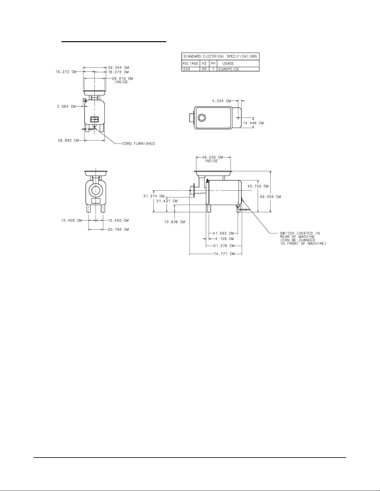
5.0 MINCER DIMENSIONS
– 5 –
Page 6

6.0 TABLE 1 TECHNICAL INFORMATION
Description Units 4812
Motor kW (hp) .373 (.5)
Maximum speed of rotating part (50Hz) rpm 1425
Nominal electrical supply Volts/Hz/ph 230/50/1
Full load current at above voltage Amps 2.9
Locked rotor current at above voltage Amps 15
Recommended fuse size Amps 10
Minimum ambient temperature °C 0
Maximum ambient temperature °C 40
Attachment hub drive size -- #12
Mincer weight (body only) Kg (Lbs) 39 (86)
Mincer with chopping end weight Kg (Lbs) 51 (122)
##
Noise level dB (A)
Shipping weight (body only) Kg (Lbs) 48 (105)
Mincing end, shipping weight Kg (Lbs) 10.2 (23)
Shipping dimensions (carton with body only) LxWxH cm 65.5 x 40.5 x 58.5
Storage conditions. Temperature and humidity. °C,
% RH
Class of appliance -- Class 1
Enclosure IP rating -- IP35
less than 70
+5 to +38,
85
##
In accordance with EN-ISO 12001:1996.
– 6 –
Page 7

7.0 INSTALLATION
7.1 UN-PACKING
Whenever possible the mincer should be transported to the
installation position in the packaging provided to avoid damage.
Do not use a sharp knife to cut into the box as damage to the
machine may occur. Check for possible shipping damage. If the
unit is found to be damaged, save the packaging material and
contact your nearest Hobart sales offi ce. Before installing, verify
that the electrical service agrees with the specifi cations on the rating plate located on the front
panel of the mincer below the drive hub.
With the machine in the vicinity of its fi nal position, remove carton from around the machine.
Remove the four bolts holding the machine to the skid. Unpack the mincer attachment carton.
After removing the skid, screw the threaded studs of the four legs (provided) into the tapped
holes in the four corners of the base. The rubber feet on these legs cushion the machine. Under
normal operation, the machines does not need to be bolted down.
7.2 LOCATION
The mincer is not suitable for outdoor installation and must not be installed where
a water jet could be used for cleaning. The mincer must only be operated by trained staff and
must be installed in a area where the use and maintenance is restricted to trained personnel.
The mincer must be installed on a horizontal fl at surface level to a minimum of 1mm in a 1 metre
side to side and front to back. Select a suitable fl at surface that can support the weight of the
mincer and feed pan when full (refer to table 1 for weights and page 5 for dimensions).
7.3 ELECTRICAL INSTALLATION
The electrical installation of the mincer must conform to the local electricity board
regulations. When installed in the United Kingdom the installation must be in accordance
with the current edition of the IEE Regulations for electrical equipment in buildings and
must conform to the requirements of the Electricity at work act.
A competent person must carry out the electrical installation.
The technical data shown in Table 1, page 6 details the electrical requirements for the
mincer. Ensure that the electrical power supply agrees with the machine specifi cation prior to
connection.
The mincer is equipped with a three-wire power supply cord ready for installation of an appropriate
grounding-type attachment plug. The plug and its mating receptacle must be properly grounded.
Contact an electrician. Provide proper fuse or circuit breaker protection.
– 7 –
Page 8
8.0 COMMISSIONING AND OPERATING INSTRUCTIONS
8.1 OPERATOR TRAINING
Take time to explain the correct operation and cleaning of the mincer to the users, referring to
this manual. Leave this manual with the operator and explain that it is important to use it for
further reference.
8.2 USING FOR THE FIRST TIME
The mincer must be cleaned and sanitized before use. Refer to Cleaning and Sanitizing,
page 10.
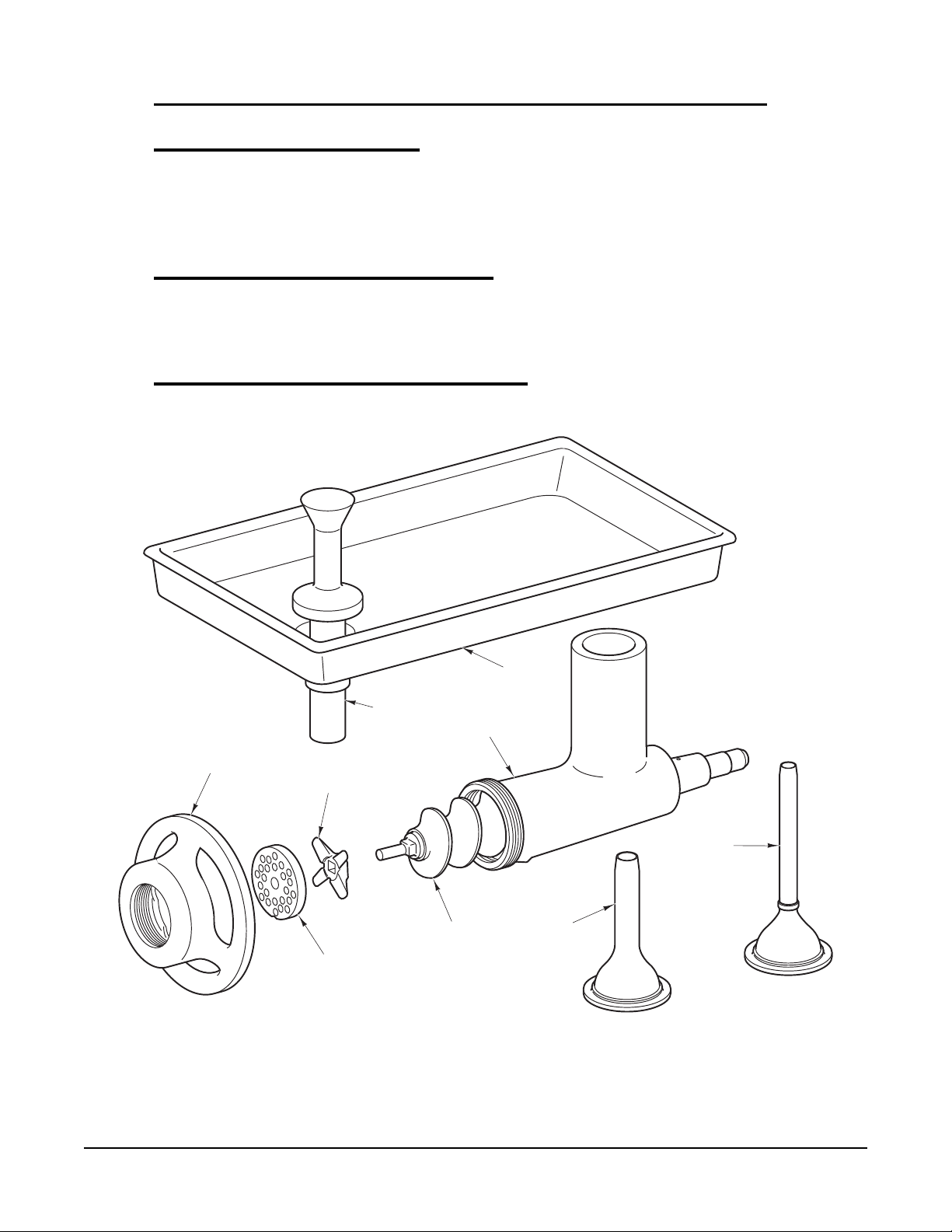
8.3 COMPONENT IDENTIFICATION:
MINCING END
ADJUSTING
RING
KNIFE
MINCER
PLATE
FEED
STOMPER
#12 MINCER
CYLINDER
WORM
(HOG CASING)
Figure 1
FEED
PAN
SAUSAGE
STUFFER
(SHEEP CASING)
SAUSAGE
STUFFER
– 8 –
Page 9

8.4 ASSEMBLY OF MINCING END AND FEED PAN
Make sure the drive hub and socket are clean and clear of any obstruction. Insert the socket end
of the cylinder into the drive hub with a slight twisting motion toward the left. The mincer cylinder
stop pin in the attachment will contact the side of the hole that receives it. Tighten the thumb
screw to secure the mincer cylinder in place.
Removing the mincer cylinder requires loosening the thumb screw three complete turns. The
thumb screw should never be removed. Slide the worm into the cylinder and rotate it until the
square shank of the worm locks into the hub drive. Install the knife on the end of the worm with
the cutting edges out, followed by the grind plate (Fig. 1). The notch on the grind plate aligns
with the pin in the bottom of the mincer cylinder. Thread the adjusting ring on the mincer cylinder
hand tight. Install the feed pan and feed stomper.
The knife and plate depend on meat for lubrication. Therefore, the mincer should
never be operated without meat.
9.0 OPERATION
9.1 CONTROLS
Main power switch:
I (green) ----- Push turns mincer motor ON.
0 (red) ----- Push turns mincer motor OFF
9.2 MINCING
Cut the meat into strips.
Turn the machine ON.
Feed the meat into the mincer using the feed stomper only as needed.
If the strips are cut to the proper size, they will feed without assistance from the stomper; allowing
both hands of the operator free to feed the meat. When running meat through the mincer a
second time, more speed is attained by feeding small quantities at a time rather than by trying
to force large amounts with the feed stomper. The feed pan should always be kept in place on
the cylinder. It not only makes regular feeding easy, but it keeps the mincer attachment ready for
immediate use. The fi neness to which the meat is cut is governed by the size of the holes in the
perforated Grind Plate, not by the tension put on the Adjusting Ring. Do not tighten the Adjusting
Ring more than hand tight. Between uses, remove the entire mincer end and feed pan and place
them in the refrigerator for re-use; or, clean and sanitize, if required.
– 9 –
Page 10

10.0 CLEANING AND SANITIZING
Disconnect the mains electricity supply before cleaning or servicing this
machine.
Remove the following parts for cleaning; Feed Pan, Adjusting Ring, Grind Plate, Knife, Worm,
and Mincer Cylinder.
The mincer must be thoroughly cleaned and sanitized after installation and before being placed
into service.
Cleaning Supplies (Not Provided)
Recommended cleaning and sanitizing supplies include:
• A 12" handle nylon brush that will slide through the cylinder
• A two compartment pail for cleaning solutions
• A pail for sanitizing solution
• A scrap pail
• Clean cloths
• A spray bottle
NOTE: When using detergents and sanitizers, always refer to the chemical manufacture’s safety
data sheet for hazard, handling, and fi rst aid information. Wear suitable gloves and eye / face
protection.
Prepare a hot detergent solution in one side of the two compartment pail. Fill the other compartment
with warm potable rinse water.
Mix a sanitizing solution by adding one tablespoon of sodium hypochlorite bleach (5.25%) to one
gallon of water in a pail. This makes a 200 ppm solution. Use this solution to fi ll the spray bottle
as well as the pail for sanitizing.
Thoroughly clean and sanitize the feed pan, feed stomper, mincer cylinder assembly, worm
assembly, knife, plate, adjusting ring and machine housing. Refer to Fig. 1 for component
identifi cation.
NOTE: After cleaning, apply a light coat of food grade mineral oil to the cylinder, adjusting ring,
knife, plate and worm before reassembly.
To reassemble, refer to section 8.4, page 9.
– 10 –
Page 11

11.0 MAINTENANCE
Unplug mincer power cord before cleaning, servicing or removing parts. Replace
parts before use.
MACHINE CLEAN UP
The machine should be thoroughly cleaned at the end of an operating day or after being idle for
an extended period of time. Refer to CLEANING for proper procedure (previous section).
HUB AND CYCLINDER DRAIN
Hub Drain
A drain slot in the trim washer allows any meat juices to drain from the hub. This slot should be
inspected periodically to make sure that it is free of obstructions. A small brush can be used to
remove any material which may have accumulated.
Cylinder Drain
A drain hole at the bottom end of the cylinder allows any meat juices to drain. This hole should
be inspected periodically to make sure that it is free of obstructions. A small wire can be used to
remove any material which may have accumulated.
AIR INTAKE
Under normal operating conditions the motor air intake screen, located in the base of the mincer,
will need little or no attention. However, in some installations where sawdust or other foreign
materials are present in the air, this intake screen may become partially or completely covered.
Where an adverse dust condition does exist, periodically check the screen and wipe clean with
a rag or brush as required.
STORAGE
The mincer should be completely cleaned and covered with a towel or other suitable cover when
it is not to be used in the immediate future.
– 11 –
Page 12

12.0 FAULT FINDING
Fault Possible cause
Machine will not start. Circuit breaker tripped, check fuse or circuit breaker.
Internal overload tripped, motor overload will auto reset
after cooling.
Product has poor appearance,
comes out soft or mushy.
Motor comes on, but worm shaft
will not turn.
Knife and/or plate worn, replace knife and plate or
End ring loose, tighten end ring, hand tight only.
End ring too tight, tighten end ring hand tight only, or
foreign object caught in cylinder, remove cylinder and
worm to inspect for cause of binding.
– 12 –
Page 13

13.0 RECOMMENDED SPARES
087711-232-1 Pushbutton on/off switch
914288 Contactor
914287 Overload
077643-00002 Ring-Adjusting
015881 Worm Assy.
119760-00001 Cylinder Assembly
122554 Stomper
122555 Pan-Feed
004221 Washer-Worm Thrust
004839-00001 Washer-Cylinder Thrust
295181 Stuffer-Sausage (Sheep Casing)
295180 Stuffer-Sausage (Hog Casing)
108197-00004 Thumb Screw Assy.
914767 Trim Washer (Attachment Hub)
065140 Gasket (Attachment Hub)
083681 Foot-Rubber
290481-00019 Housing-50 Hertz
064965-00008 Panel-Front Housing
064805-00008 Panel-Rear Housing
914759-00001 Motor Assy.
914157 Hub Adapter
914156 Seal-oil
016423-00001 Mincer Plate (1/8" Dia. Holes)(Carbon Steel)
016424-00001 Mincer Plate (3/16" Dia. Holes)(Carbon Steel)
016425-00001 Mincer Plate (1/4" Dia. Holes)(Carbon Steel)
016423-00002 Mincer Plate (1/8" Dia. Holes)(Stay Sharp)
016424-00002 Mincer Plate (3/16" Dia. Holes)(Stay Sharp)
016425-00002 Mincer Plate (1/4" Dia. Holes)(Stay Sharp)
290339 Knife-Mincer
– 13 –
Page 14

14.0 NOTES
– 14 –
Page 15

15.0 SERVICE CONTACT NUMBERS
Hobart trained service technicians strategically located at national Hobart service branches
are prepared to give you fast, effi cient and reliable service. Protect your investment by having
a Hobart inspection contract, which assures the continued, effi cient operation of your Hobart
machines, spares and accessories. For disposal of mincer, contact Hobart Service Centre for
return details.
For further details please contact: -
Department Telephone Facsimile
SALES: 07002 101 101 02088 864 396
SERVICE 07002 202 202 01733 371 709
SPARES 07002 303 303 01733 371 332
– 15 –
Page 16

– 16 –
FORM 35114 (July 2008)
Page 17

Modèle
4812
Page 1 - Anglais
Page
17 - Français
ML-136159
FORM 35114 (Juillet 2008)
Page
INSTALLATION AND OPERATION MANUAL
MANUEL D'INSTALLATION ET D'UTILISATION
INSTALLATIONS UND BEDIENUNGSANLEITUNG
33 - Allemand
Page 18

FRANÇAIS / TABLE DES MATIERES
4812 Hachoir CE Section Page
Informations de securite 1.0 19
Consignes de securite 1.1 19
Symboles d’avertissement 1.2 19
Responsabilite 1.3 20
Avant-propos 2.0 20
Informations generales 3.0 20
Respect de l’environnement 4.0 20
Materiaux d’emballage 4.1 20
Elimination de vos anciens appareils 4.2 20
Dimensions du hachoir 5.0 21
Tableau 1 informations techniques 6.0 22
Installation 7.0 23
Deballage 7.1 23
Emplacement 7.2 23
Installation electrique 7.3 23
Instructions de mise en service et de fonctionnement 8.0 24
Formation de l’operateur 8.1 24
Premiere utilisation 8.2 24
Identifi cation des composants: 8.3 24
Assemblage du côte hachoir et du bac d’alimentation 8.4 25
Utilisation 9.0 25
Commandes 9.1 25
Hachage 9.2 25
Nettoyage et desinfection 10.0 26
Maintenance 11.0 27
Localisation des defaillances 12.0 28
Pieces de rechange recommandee 13.0 29
Remarques 14.0 30
Informations et adresses du service 15.0 31
– 18 –
Page 19

1.0 INFORMATIONS DE SECURITE
Les procédures et les précautions contenues dans ce manuel ne sont applicables, selon notre
compréhension, que sur la machine lorsque celle-ci est utilisée conformément aux indications.
Si la machine est utilisée différemment, l’opérateur sera responsable de sa propre sécurité et de
la sécurité des autres personnes pouvant alors être impliquées.
Les informations de ce manuel ont été préparées pour aider l’opérateur à comprendre, entretenir
et faire fonctionner le hachoir. Pour éviter les accidents, veuillez lire, comprendre et suivre toutes
les précautions et tous les avertissements contenus dans ce manuel avant l’installation ou lors
du premier fonctionnement. Ce manuel doit être étudié si l’on souhaite parvenir à une bonne
compréhension du hachoir et de ses capacités.
1.1 CONSIGNES DE SECURITE
• N’arrosez ni ne placez cet appareil sous pression pour le nettoyer. Le respect des instructions
de nettoyage fi gurant dans ce manuel est vital.
• Ne retirez aucun capot et ne desserrez aucune fi xation pendant le fonctionnement de la
machine.
• Veillez à ce que ce manuel demeure accessible près du hachoir pour pouvoir vous y référer
si nécessaire.
• Tous les opérateurs doivent être formés au fonctionnement sans danger du hachoir et de
ses composants.
• Veillez à ce que l’alimentation électrique soit isolée avant de procéder à la réparation ou au
déplacement du hachoir.
• Les éléments rotatifs et l’électricité peuvent être dangereuses et peuvent provoquer des
blessures si trop peu de précautions sont prises avant le fonctionnement ou la réparation
de la machine.
• Entretenez votre hachoir et ses accessoires au moins deux fois par an ; si vous les utilisez
très fréquemment un entretien plus régulier sera alors nécessaire.
1.2 SYMBOLES D’AVERTISSEMENT
Les symboles suivants ont été utilisés pour identifi er les messages de sécurité fi gurant dans ce
manuel:
Le symbole “Avertissement” a été initialement rencontré aux endroits où les
informations correspondantes étaient importantes pour une utilisation de la machinerie en toute
sécurité.
Le symbole “Dangers électriques” a été utilisé lorsqu’il existe des risques électriques.
Avant l’entretien de la machinerie, débranchez toujours le câble d’alimentation de
l’alimentation sur secteur.
– 19 –
Page 20

1.3 RESPONSABILITE
Si les installations et les réparations ne sont pas effectuées par des techniciens autorisés ou
si l’on utilise des pièces autres que les pièces originales sur la machine, et si l’on effectue des
modifi cations techniques, cela peut affecter la garantie établie dans les conditions spéciales de
vente.
2.0 AVANT-PROPOS
Hobart se réserve le droit de modifi er la conception de leurs produits sans préavis. Bien que
tous les efforts soient fournis pour veiller à ce que la publication refl ète la dernière conception,
l’entreprise ne peut garantir une conformité exacte. Prenez soin de votre hachoir 4812, veillez à
ce qu’il reste propre et en bon état mécanique et électrique.
3.0 INFORMATIONS GENERALES
Les informations et instructions contenues dans ce manuel peuvent ne pas couvrir tous les
détails ou toutes les variations en matière d’équipement ou encore ne pas répondre à toutes
les questions pouvant survenir lors de l’installation, du fonctionnement ou de l’entretien. Si plus
d’informations sont nécessaires, veuillez contacter votre agence locale Hobart.
Le modèle de hachoir 4812 dispose d’un moteur électrique de .37 kw (.5 hp) hachera la viande
à une cadence de 3,63 kg par minute, premier découpage à travers une plaque avec des trous
de 3 mm de diamètre .
La machine est programmée pour fonctionner avec une alimentation électrique monophasée de
230 volts / 50 hertz.
Le hachoir est installé avec une caractéristique de sécurité « tension nulle » pour empêcher
un redémarrage automatique après une défi cience de l’alimentation ou le débranchement de
l’alimentation sur secteur principal.
4.0 RESPECT DE L’ENVIRONNEMENT
4.1 MATERIAUX D’EMBALLAGE
La palette et le fi lm d’emballage de protection en polyéthylène ont été
sélectionnés parmi des matériaux qui ne nuiront pas à l’environnement
lors de leur élimination ou qui peuvent être recyclés. Au lieu de les jeter,
veuillez vous assurer qu’ils sont recyclés.
4.2 ELIMINATION DE VOS ANCIENS APPAREILS
Les vieux appareils contiennent des matériaux qui peuvent être recyclés. Veuillez contacter
le centre de collecte des déchets, le ferrailleur ou l’agence Hobart le plus proche en ce qui
concerne les plans de recyclage.
– 20 –
Page 21

5.0 DIMENSIONS DU HACHOIR
Légende :
Standard electrical specifi cations : Spécifi cations électriques normales
Voltage : Tension
Usage : Utilisation
Inside : Intérieur
Cord furnished : Cordon fourni
Switch located in rear of machine (can be changed to front of machine) :
Interrupteur situé à l’arrière de la machine (peut être déplacé à l’avant de la machine)
– 21 –
Page 22

6.0 TABLEAU 1 INFORMATIONS TECHNIQUES
Description Unités 4812
Puissance kW (hp) .373 (.5)
Vitesse Maximum de la pièce de rotation (50Hz) rpm 1425
Alimentation électrique nominale Volts/Hz/ph 230/50/1
Courant de pleine charge à la tension ci-dessus Amps 2.9
Courant du rotor verrouillé à la tension ci-dessus Amps 15
Taille de fusible recommandée Amps 10
Température ambiante minimum °C 0
Température ambiante maximum °C 40
Taille de l’entraînement du moyeu de l’attache -- #12
Poids du hachoir (Corps uniquement) Kg (Lbs) 39 (86)
Poids du hachoir à tête hacheuse Kg (Lbs) 51 (122)
##
Niveau de bruit dB (A)
Poids d’expédition (Corps uniquement) Kg (Lbs) 48 (105)
Tête hacheuse, poids de l’expédition Kg (Lbs) 10.2 (23)
Dimensions de l’expédition (carton avec corps seulement) LxWxH cm 65.5 x 40.5 x 58.5
Conditions de rangement. Température et humidité. °C,
% RH
Catégorie d’appareil -- Catégorie 1
Cotation IP du coffre -- IP35
Moins de 70
+5 to +38,
85
##
Conforme à la norme EN-ISO 12001:1996.
– 22 –
Page 23

7.0 INSTALLATION
7.1 DEBALLAGE
Dès que cela s’avère possible, le hachoir doit être transporté
vers la position d’installation dans l’emballage fourni pour
éviter les dommages. N’utilisez pas de couteau pointu pour
découper la boîte ; la machine pourrait être endommagée.
Vérifi ez que la machine n’a pas été endommagée pendant
le transport. Si vous vous apercevez que la machine a été
abîmée, conservez l’emballage et contactez l’agence de vente Hobart la plus proche. Avant
l’installation, vérifi ez que le matériel électrique répond bien aux spécifi cations de la plaque
signalétique situées sur le panneau frontal du hachoir sous le moyeu entraîneur.
Lorsque la machine approche de sa position fi nale, retirez le carton de la machine. Retirez les
quatre boulons retenant la machine à la cale. Retirez le carton d’emballage du hachoir.
Une fois la cale ôtée, fi xez les goujons à fi lets des quatre pattes (fournis) dans les trous taraudés aux
quatre coins de base. Les pieds en plastique de ces pattes servent d’amortisseurs à la machine.
Lors de leur fonctionnement normal, les machines n’ont pas besoin d’être boulonnées.
7.2 EMPLACEMENT
Le hachoir ne convient pas pour une installation à l’extérieur et ne doit pas être
installé là où on peut utiliser un jet d’eau pour le nettoyage. Le hachoir ne doit être utilisé que par
du personnel qualifi é et doit être installé dans un endroit où l’utilisation et la maintenance sont
réservées à du personnel formé.
Le hachoir doit être installé sur une surface plane, horizontale, de niveau avec une tolérance de
1 mm par mètre d’un côté à l’autre et d’avant en arrière. Choisissez une surface plane appropriée
qui peut supporter le poids du hachoir et du bac d’alimentation lorsqu’il est plein (voir le tableau
1 pour les poids et la page 21 pour les dimensions).
7.3 INSTALLATION ELECTRIQUE
L’installation électrique du hachoir doit être conforme aux réglementations des services
d’électricité locaux.
L’installation électrique doit être effectuée par une personne compétente.
Les caractéristiques techniques indiquées dans le Tableau 1, page 22 indiquent en détails
les exigences électriques du hachoir. Assurez-vous que la prise d’alimentation secteur est
compatible avec les caractéristiques de l’appareil avant le branchement.
Le hachoir est équipé d’un cordon d’alimentation trifi laire prévu pour l’installation d’une prise
d’alimentation appropriée de type mise à la terre. La prise et le connecteur correspondant doivent
être correctement mis à la terre. Contactez un électricien. Installez un fusible ou un disjoncteur
approprié pour une protection adéquate.
– 23 –
Page 24

8.0 INSTRUCTIONS DE MISE EN SERVICE ET DE
FONCTIONNEMENT
8.1 FORMATION DE L’OPERATEUR
Prenez le temps d’expliquer le bon fonctionnement et le nettoyage du hachoir aux utilisateurs,
en vous référant au présent manuel. Confi ez ce manuel à l’opérateur et expliquez qu’il est
important de l’utiliser pour référence ultérieure.
8.2 PREMIERE UTILISATION
Le hachoir doit être nettoyé et désinfecté avant utilisation. Consultez la Section Nettoyage et
Désinfection, page 26.
8.3 IDENTIFICATION DES COMPOSANTS:
EXTREMITE HACHOIR
Bague
de réglage
Couteau
Plaque
de hachoir
Poussoir
Vis hélicoïdale
Bac d'alimentation
Cylindre
de hachoir n° 12
Introducteur
pour saucisse
(boyau de mouton)
Introducteur
pour saucisse
(boyau de porc)
Figure 1
– 24 –
Page 25

8.4 ASSEMBLAGE DU CÔTE HACHOIR ET DU BAC
D’ALIMENTATION
Assurez-vous que le moyeu d’entraînement et la douille sont propres et non obturés. Introduisez
le côté douille du cylindre dans le manchon d’entraînement avec un léger mouvement de rotation
vers la gauche. La goupille de butée du cylindre de hachoir dans l’accessoire entrera en contact
avec le côté du trou qui la reçoit. Bloquez la vis moletée pour bien fi xer le cylindre de hachoir en
place.
Pour déposer le cylindre de hachoir, il faut desserrer la vis moletée de trois tours complets. La
vis moletée ne doit jamais être retirée. Faites glisser la vis dans le cylindre et tournez-la jusqu’à
ce que la tige carrée de la vis se bloque dans l’entraînement du moyeu. Installez le couteau
à l’extrémité de la vis avec les bords coupants vers l’extérieur, suivi de la plaque de broyage
(Figure 1). L’encoche sur la plaque de broyage s’aligne avec la goupille en bas du cylindre de
hachoir. Vissez la bague de réglage sur le cylindre de hachoir en serrant à la main. Installez le
bac d’alimentation et le poussoir d’alimentation.
Le couteau et la plaque tirent leur lubrifi cation de la viande. Par conséquent, le hachoir
ne doit jamais tourner sans viande.
9.0 UTILISATION
9.1 COMMANDES
Interrupteur secteur :
I (vert) ----- Poussez pour mettre le moteur de hachoir en MARCHE.
0 (rouge) ----- Poussez pour ARRETER le moteur de hachoir
9.2 HACHAGE
Coupez la viande en bandes.
Mettez la machine en MARCHE.
Alimentez la viande dans le hachoir en utilisant le poussoir d’alimentation comme nécessaire.
Si les bandes sont découpées à la largeur appropriée, elles s’alimenteront sans aide du poussoir,
ce qui laissera les deux mains de l’opérateur libres pour alimenter la viande. Lorsqu’on fait passer
la viande par le hachoir une deuxième fois, on obtient davantage de vitesse en alimentant de
petites quantités à la fois plutôt qu’en essayant de forcer de grandes quantités avec le poussoir.
Le bac d’alimentation doit toujours rester à sa place sur le cylindre. Cela rend l’alimentation
plus régulière et plus facile, mais aussi cela garde l’accessoire de hachoir prêt pour utilisation
immédiate. La fi nesse de hachage de la viande est déterminée par le diamètre des trous dans
la plaque de broyage perforée, et non par la tension qui est exercée sur la bague de réglage.
Ne serrez pas la bague de réglage davantage qu’à la main. Entre les utilisations, retirez le côté
hachoir et le bac d’alimentation tout entiers et placez-les dans le réfrigérateur pour réutilisation
ou nettoyez-les et désinfectez-les si nécessaire.
– 25 –
Page 26

10.0 NETTOYAGE ET DESINFECTION
Débranchez l’alimentation électrique secteur avant de nettoyer ou d’entretenir cet
appareil.
Retirez les parties suivantes pour le nettoyage : Bac d’alimentation, Bague de réglage, Plaque
de broyage, Couteau, Vis hélicoïdale et Cylindre de hachoir.
Le hachoir doit être entièrement nettoyé et désinfecté après installation et avant d’être mis en
service.
Fournitures de nettoyage (non fournies)
Les fournitures recommandées pour le nettoyage et la désinfection comprennent:
• Une brosse en nylon à poignée de 30 cm qui coulissera dans le cylindre.
• Un seau à deux compartiments pour les solutions de nettoyage
• Un seau pour la solution de désinfection
• Un seau pour les déchets
• Des chiffons propres
• Une bouteille à pulvérisation
NB: Lorsqu’on utilise des détergents et des produits de désinfection, il faut toujours se référer
à la fi che de données de sécurité du fabricant de produits chimiques concernant les dangers,
la manipulation et les informations sur les premiers secours. Portez des gants et une protection
pour les yeux et visière appropriée.
Préparez une solution de détergent très chaude d’un côté du seau à deux compartiments.
Remplissez l’autre compartiment d’eau tiède potable pour le rinçage.
Mélangez une solution de désinfection en ajoutant une cuillerée à soupe d’hypochlorure de
sodium (5,25 %) à cinq litres d’eau dans un seau. Cela constitue une solution à 200 ppm. Utilisez
cette solution pour remplir la bouteille de pulvérisation ainsi que le seau pour la désinfection.
Nettoyez et désinfectez entièrement le bac d’alimentation, le poussoir, l’ensemble à cylindre de
hachoir, l’ensemble à vis hélicoïdale, le couteau, la plaque, la bague de réglage et le carter de
la machine. Reportez-vous à la Figure 1 pour l’identifi cation des composants.
NB: Après nettoyage, appliquez une légère couche d’huile minérale de qualité alimentaire au
cylindre, en ajustant la bague, le couteau, la plaque et la vis hélicoïdale avant réassemblage.
Pour réassembler, voir la section 8.4 page 25.
– 26 –
Page 27

11.0 MAINTENANCE
Debranchez le cordon d’alimentation electrique du hachoir avant de nettoyer,
d’entretenir ou de deposer les pieces. Replacez les pieces avant utilisation.
NETTOYAGE DE L’APPAREIL
L’appareil doit être entièrement nettoyé à la fi n d’une journée de fonctionnement ou après une
période de non utilisation prolongée. Référez-vous à NETTOYAGE pour la procédure appropriée
(section précédente).
VIDANGE DU MOYEU ET DU CYLINDRE
Vidange du moyeu
Une fente de drainage dans la rondelle d’épaisseur permet de vidanger les jus de viande du
moyeu. Cette fente doit être contrôlée périodiquement pour s’assurer qu’elle n’est pas obstruée.
On peut utiliser une petite brosse pour retirer toutes matières qui auraient pu s’accumuler.
Vidange du cylindre
Un trou de vidange du côté inférieur du cylindre permet de vidanger les jus de viande. Ce trou
doit être contrôlé périodiquement pour s’assurer qu’il n’est pas obstrué. Un petit fi l métallique
peut être utilisé pour retirer toute matière qui peut s’être accumulée.
PRISE D’AIR
Dans les conditions normales de service le tamis d’admission d’air du moteur, situé à la base du
hachoir ne demandera pas ou presque pas de soin. Cependant, dans certaines installations où
la sciure ou autres matières étrangères sont présentes dans l’air, ce tamis d’admission peut être
partiellement ou complètement couvert. Lorsque de telles conditions poussiéreuses existent,
vérifi ez périodiquement le tamis et nettoyez avec un chiffon ou une brosse comme nécessaire.
STOCKAGE
Si l’on prévoit de ne pas utiliser dans un avenir immédiat le hachoir, celui-ci doit être complètement
nettoyé et recouvert d’un torchon ou autre couverture appropriée.
– 27 –
Page 28

12.0 LOCALISATION DES DEFAILLANCES
Défaut Cause possible
La machine refuse de démarrer. Disjoncteur déclenché, vérifi ez le fusible ou le disjoncteur.
Relais de surcharge interne déclenché, le relais de
surcharge moteur se ré-enclenchera automatiquement
après refroidissement.
Le produit a mauvais aspect, sort
trop mou.
Le moteur est sous tension, mais
l’arbre de la vis hélicoïdale ne
tourne pas.
Le couteau et / ou la plaque sont usés, remplacer
le couteau et la plaque ou la bague d’extrémité est
desserrée, resserrez la bague uniquement à la main.
La bague d’extrémité est trop serrée, serrez la bague
d’extrémité uniquement à la main, ou un objet est pris
dans le cylindre, retirez le cylindre et la vis hélicoïdale
pour vérifi er la cause du grippage.
– 28 –
Page 29

13.0 PIECES DE RECHANGE RECOMMANDEE
087711-232-1 Interrupteur bouton-poussoir Marche / Arrêt
914288 Contacteur
914287 Relais de surcharge
077643-00002 Bague – de réglage
015881 Ensemble vis hélicoïdale
119760-00001 Ensemble cylindre
122554 Poussoir
122555 Bac d’alimentation
004221 Rondelle de butée vis hélicoïdale
004839-00001 Rondelle de butée cylindre
295181 Introducteur – saucisse (boyau de mouton)
295180 Introducteur – saucisse (boyau de porc)
108197-00004 Ensemble vis moletée
914767 Rondelle de calage (moyeu accessoire)
065140 Rondelle plate (moyeu accessoire)
083681 Pied caoutchouc
290481-00019 Boîtier 50 Hz
064965-00008 Panneau – boîtier avant
064805-00008 Panneau – boîtier arrière
914759-00001 Ensemble moteur
914157 Adaptateur de moyeu
914156 Huile d’étanchéité
016423-00001 Plaque hachoir (trous diamètre 1/8") (acier au carbone)
016424-00001 Plaque hachoir (trous diamètre 3/16") (acier au carbone)
016425-00001 Plaque hachoir (trous diamètre 1/4") (acier au carbone)
016423-00002 Plaque hachoir (trous diamètre 1/8") (non affûtable)
016424-00002 Plaque hachoir (trous diamètre 3/16") (non affûtable)
016425-00002 Plaque hachoir (trous diamètre 1/4") (non affûtable)
290339 Couteau – hachoir
– 29 –
Page 30

14.0 REMARQUES
– 30 –
Page 31

15.0 INFORMATIONS ET ADRESSES DU SERVICE
Les techniciens d’entretien formés par Hobart sont situés stratégiquement dans des succursales
Hobart et sont prêts à vous fournir un service rapide, effi cace et fi able. Protégez votre
investissement par un contrat d’inspection Hobart, qui assure le fonctionnement continu, effi cace
de vos appareils Hobart, de leurs pièces de rechange et accessoires. Pour la mise au rebut du
hachoir, veuillez contacter le Centre de Service Hobart pour obtenir des renseignements.
– 31 –
Page 32

– 32 –
FORM 35114 (Juillet 2008)
Page 33

Modell
4812
Seite
Seite 1 - Englisch
17 - Französisch
FORM 35114 (Juli 2008)
ML-136159
INSTALLATION AND OPERATION MANUAL
MANUEL D'INSTALLATION ET D'UTILISATION
INSTALLATIONS UND BEDIENUNGSANLEITUNG
Seite
33 - Deutsch
Page 34

DEUTSCH / INHALT
4812 CE Fleischwolf Kapitel Seite
Allgemeine Hinweise 1.0 35
Wichtige Sicherheitshinweise 1.1 35
Warnsymbole 1.2 35
Garantie 1.3 36
Vorwort 2.0 36
Allgemeine Informationen 3.0 36
Umwelt 4.0 36
Verpackungsmaterial 4.1 36
Entsorgung Ihres Altgerätes 4.2 36
Gerätemaße 5.0 37
Tabelle 1 Technische Daten 6.0 38
Installation 7.0 39
Auspacken 7.1 39
Standort 7.2 39
Elektrische Installation 7.3 39
Inbetriebnahme und Bedienung 8.0 40
Anwendertraining 8.1 40
Vor dem ersten Gebrauch 8.2 40
Geräteteile: 8.3 40
Montage Von Hackinstrumenten und Einfüllschale 8.4 41
Betrieb 9.0 41
Steuerung 9.1 41
Hackfunktionen 9.2 41
Reinigung und Desinfi zierung 10.0 42
Wartung 11.0 43
Fehlersuche 12.0 44
Empfohlene Ersatzteile 13.0 45
Notizen 14.0 46
Serviceadressen 15.0 47
– 34 –
Page 35

1.0 ALLGEMEINE HINWEISE
Die in der Bedienungsanleitung beschriebenen Vorgänge und Sicherheitsmaßnahmen beziehen
sich nur auf die Verwendung des Gerätes in der hier beschriebenen Weise. Wird das Gerät in einer
anderen als der hier empfohlenen Weise verwendet, ist der Anwender für die eigene Sicherheit
und die Sicherheit anderer möglicherweise betroffener Personen selbst verantwortlich.
Bitte lesen Sie die Gebrauchsanleitung vor Inbetriebnahme sorgfältig durch. Zur Vorbeugung
von Unfällen beachten Sie die Sicherheitsmaßnahmen und Warnungen, bevor Sie das Gerät
installieren und in Betrieb nehmen.
1.1 WICHTIGE SICHERHEITSHINWEISE
• Verwenden Sie für die Reinigung dieses Gerätes weder Spritz- noch Druckreiniger. Befolgen
Sie unbedingt die Reinigungsanleitungen in dieser Bedienungsanleitung.
• Entfernen Sie keine Abdeckungen und schrauben Sie keine Maschinenteile ab, während
das Gerät im Betrieb ist.
• Bewahren Sie die Bedienungsanleitung zum Nachschlagen in greifbarer Nähe des
Fleischwolfes auf.
• Machen Sie jeden Benutzer mit der sicheren Anwendung des Fleischwolfes und der
Geräteteile vertraut.
• Ziehen Sie unbedingt den Netzstecker, bevor Sie das Gerät warten lassen, pfl egen oder
bewegen.
• Drehmechanismus und Elektrizität stellen potentielle Gefahren dar und können zu
Verletzungen führen, wenn keine entsprechenden Vorsichtsmaßnahmen vor Inbetriebnahme
und Wartung des Gerätes getroffen werden.
• Lassen Sie den Fleischwolf und das Zubehör regelmäßig, jedoch mindestens zweimal
jährlich warten. Die Häufi gkeit der Wartung ist abhängig von der Nutzung des Gerätes.
1.2 WARNSYMBOLE
Zur Kennzeichnung der Sicherheitshinweise in dieser Bedienungsanleitung werden diese
Symbole verwendet:
Das Warnsymbol weist auf einen wichtigen Hinweis zur sicheren Anwendung des
Gerätes hin.
Das Elektrizitätszeichen weist auf Risiken durch Elektrizität hin. Ziehen Sie vor Wartung
und/oder Pfl ege des Gerätes unbedingt den Netzstecker.
– 35 –
Page 36

1.3 GARANTIE
Installationen und Reparaturen dürfen nur durch qualifi ziertes Fachpersonal durchgeführt werden.
Verwenden Sie nur Originalersatzteile. Ihre Garantie kann nach unsachgemäßen Installationen
und Reparaturen, sowie technischen Veränderungen am Gerät und der Verwendung von NichtOriginal-Ersatzteilen verfallen.
2.0 VORWORT
Hobart behält sich das Recht vor, das Design der Produkte ohne vorherige Ankündigung zu
ändern. Der Hersteller unternimmt jegliche Anstrengungen, dass die Anleitungen dem neuesten
Design entsprechen, kann jedoch keine hundertprozentige Übereinstimmung gewährleisten.
Halten Sie das Gerät sauber und in gutem mechanischen und elektrischen Zustand, und Sie
werden lange Freude an Ihrem 4812 Fleischwolf haben.
3.0 ALLGEMEINE INFORMATIONEN
Die in dieser Bedienungsanleitung enthaltenen Informationen und Anleitungen decken
möglicherweise nicht alle Details oder Abweichungen des Gerätes sowie alle Eventualitäten bei
Installation, Betrieb oder Wartung des Gerätes ab. Wenn Sie weitere Informationen benötigen,
kontaktieren Sie bitte Ihr Hobart Service Center.
Das Modell 4812 hat einen .37 kW (.5 PS) starken Elektromotor. Der 4812 hackt 3,63 kg Fleisch
pro Minute, indem dieses zuerst durch eine Platte mit Löchern, die einen Durchmesser von 3mm
haben, gedrückt wird.
Das Gerät ist für eine Spannung mit 230 Volt/ 50 Hertz Einphasenstrom vorgesehen. Der
Fleischwolf ist mit einem „Stromstopp“ ausgestattet, der einen automatischen Start nach einem
Stromausfall oder einem vorübergehenden Abbruch der Verbindung zum Stromnetz verhindert.
4.0 UMWELT
4.1 VERPACKUNGSMATERIAL
Die Palette und die schützende Polyethylenverpackungsfolie sind
aus umweltfreundlichem, recycelfähigem Material. Werfen Sie das
Verpackungsmaterial bitte nicht einfach weg, sondern sorgen Sie dafür,
dass es recycelt wird.
4.2 ENTSORGUNG IHRES ALTGERÄTES
Altgeräte enthalten Materialien, die recycelt werden können. Bitte fragen Sie bei Ihrerer
Müllsammelstelle (z.B. Wertstoffhof) nach.
– 36 –
Page 37

5.0 GERÄTEMASSE
Standard electrical specifi cations : Standard Elektrische Daten
Voltage : Spannung
Usage : Verwendung
Inside : Innenmaße
Cord furnished : Kabel
Switch located in rear of machine (can be changed to front of machine):
Schalter an Rückwand des Gerätes (kann an der Vorderseite des Gerätes angebracht werden)
– 37 –
Page 38

6.0 TABELLE 1 TECHNISCHE DATEN
Beschreibung Einheit 4812
Motorleistung kW (hp) .373 (.5)
Maximale Drehzahl des Gewindes (50 Hz) rpm 1425
Nennspannung Volts/Hz/ph 230/50/1
Volllaststrom bei o.g. Spannung Amps 2.9
Anzugsstrom bei o.g Spannung Amps 15
Empfohlene Geräteschutzsicherung Amps 10
Minimale Umgebungstemperatur °C 0
Maximale Umgebungstemperatur °C 40
Antriebsspitzelgröße -- #12
Gerätegewicht (Rumpf) Kg (Lbs) 39 (86)
Gerätegewicht (Rumpf und Hackinstrumente) Kg (Lbs) 51 (122)
##
Geräuschpegel dB (A)
Transportgewicht (Rumpf) Kg (Lbs) 48 (105)
Transportgewicht (Hackinstrumente) Kg (Lbs) 10.2 (23)
Transportmaße (Karton mit Rumpf) LxWxH cm 65.5 x 40.5 x 58.5
Lagerbedingungen (Temperatur und relative
Luftfeuchtigkeit)
°C,
% RH
Anwendungsklasse -- Klasse 1
Internationale Sicherheitsstufe (IP Rating) -- IP35
unter 70
+5 bis +38,
85
##
in Übereinstimmung mit EN-ISO 12001;1996
– 38 –
Page 39

7.0 INSTALLATION
7.1 AUSPACKEN
Zur Vermeidung von Beschädigungen sollte der Fleischwolf
nach Möglichkeit immer in der Verpackung bis zu seinem
endgültigen Standort transportiert werden. Verwenden Sie zum
Öffnen der Box keine scharfen Gegenstände, da Sie ansonsten
das Gerät beschädigen könnten. Überprüfen Sie das Gerät
auf mögliche Transportschäden. Im Falle einer Beschädigung des Gerätes bewahren Sie die
Originalverpackung auf und kontaktieren Sie umgehend Ihren nächsten Hobert Händler.
Vergewissern Sie sich vor der Installation, dass Ihre Stromversorgung mit den auf dem Typenschild
(befi ndet sich an der Vorderfront unter dem Antriebsritzel) genannten Angaben übereinstimmt.
Wenn das Gerät in der Nähe des endgültigen Standortes steht, entfernen Sie den Karton.
Entfernen Sie hierzu die vier Bolzen, die das Gerät auf dem Gestell halten. Packen Sie den
beigefügten Karton aus.
Nach Entfernen des Gestells, schrauben Sie die Gewindeschrauben der vier Füsse in die
Gewindelöcher an den vier Ecken des Bodens. Die Gummisockel der Beine dämpfen das Gerät
ab. Bei normalem Betrieb ist ein Festschrauben der Maschine nicht notwendig.
7.2 STANDORT
Der Fleischwolf ist nicht für den Gebrauch im Freien geeignet und darf nicht an
Orten aufgestellt werden, an denen mit einem Wasserstrahl gereinigt wird. Der Standort muss
so gewählt werden, dass nur geschultes Personal das Gerät bedienen und warten kann. Der
Fleischwolf darf nur ausschließlich von geschultem Personal bedient werden.
Der Fleischwolf muss auf einer waagerechten, ebenen Unterlage von mindestens 1mm Dicke
und einer Größe von mindestens 1x1 Meter aufgestellt werden. Wählen Sie einen geeigneten
ebenen Standort, der stabil genug für das Gewicht des Fleischwolfes und eine volle Einfüllschale
ist (siehe Tabelle 1 für Gewicht & Seite 37 für Maße).
7.3 ELEKTRISCHE INSTALLATION
Die elektrische Installation der Fleischwolf muss mit den örtlichen behördlichen
Vorschriften übereinstimmen.
Die elektrischen Installationen müssen von einer Fachkraft ausgeführt werden.
Die elektrischen Anforderungen zur Installation der Fleischwolf im Detail entnehmen Sie bitte
den technischen Daten in Tabelle 1, Seite 38. Vergewissern Sie sich vor dem Anschluss, dass
die Stromversorgung des Geräts mit dessen technischen Anforderungen übereinstimmt.
Die Fleischwolf ist mit einem dreifachen Stromversorgungskabel ausgerüstet und kann mit einem
geeigneten Schukostecker verbunden werden. Der Stecker und sein Gegenkontakt müssen
korrekt geerdet werden. Kontaktieren Sie einen Elektriker. Sorgen Sie für ausreichenden Schutz
der elektrischen Sicherungen oder des Hauptschalters.
– 39 –
Page 40

8.0 INBETRIEBNAHME UND BEDIENUNG
8.1 ANWENDERTRAINING
Nehmen Sie sich Zeit, um allen Anwendern unter Berücksichtigung dieser Bedienungsanleitung
die richtige Bedienung und Reinigung des Fleischwolfes zu erklären. Zeigen Sie den Anwendern
die Bedienungsanleitung und weisen Sie sie darauf hin, die Anleitung unbedingt anzuwenden.
8.2 VOR DEM ERSTEN GEBRAUCH
Der Fleischwolf muss vor der Inbetriebnahme gereinigt und desinfi ziert werden. Die Anleitung
zur Reinigung und Desinfi zierung fi nden Sie auf Seite 42.
8.3 GERÄTETEILE:
HACKINSTRUMENTE
Verschlußring
Kreuzmesser
Lochplatte
Stopfer
Schnecke
Einfüllschale
Zylinder
Wurstaufsatz
(Schafdarm)
Wurstaufsatz
(Schweinedarm)
Abb. 1
– 40 –
Page 41

8.4 MONTAGE VON HACKINSTRUMENTEN UND
EINFÜLLSCHALE
Stellen Sie sicher, dass das Antriebsritzel und die Steckdose sauber und frei von Hindernissen
sind. Stecken Sie den Stecker des Zylinders mit einer leichten Drehbewegung nach links in
das Antriebsritzel. Ist der Anschlagbolzen des Fleischwolfzylinders im hinteren Teil fest in der
Öffnung, ziehen Sie die Fingerschraube an, um den Zylinder zu montieren.
Um den Fleischwolfzylinder zu entfernen, drehen Sie die Fingerschraube dreimal um 360°. Die
Fingerschraube sollte niemals entfernt werden. Schieben Sie das Gewinde in den Zylinder und
drehen Sie es so lange, bis der Vierkantschaft in das Antriebsritzel einrastet. Montieren Sie das
Kreuzmesser am Ende des Gewindes mit den Klingen zur Vorderseite, und wiederholen Sie
dies mit der Lochscheibe. (Abb. 1). Die Einkerbung an der Lochscheibe ist an dem Stift an der
Unterseite des Fleischwolfzylinders ausgerichtet. Ziehen Sie den Verschlußring fest. Montieren
Sie die Einfüllschale und den Stopfer.
Das Kreuzmesser und die Lochscheibe benötigen Fleisch für die Schmierung.
Benutzen Sie den Fleischwolf daher niemals ohne Fleisch.
9.0 BETRIEB
9.1 STEUERUNG
Hauptschalter:
I (grün) ----- betätigen, um den Fleischwolf einzuschalten
0 (rot) ----- betätigen, um den Fleischwolf auszuschalten
9.2 HACKFUNKTIONEN
Schneiden Sie das Fleisch in Streifen.
Stellen Sie die Maschine an.
Führen Sie das Fleisch in den Fleischwolf ein und nutzen Sie den Stopfer nur bei Bedarf.
Fleischstreifen mit der richtigen Größe lassen sich ohne Verwendung des Stopfers in den
Fleischwolf einführen, und somit hat der Nutzer beide Hände für das Einführen des Fleisches
frei. Wenn Sie das Fleisch ein zweites Mal durch den Fleischwolf verarbeiten lassen, erreichen
sie eine höhere Geschwindigkeit, indem Sie kleine Portionen einführen, als wenn Sie mit dem
Stopfer große Mengen hineindrücken. Die Einfüllschale sollte immer an ihrem Platz auf dem
Zylinder bleiben. Dieses erleichtert nicht nur ein schnelles Einführen des Fleisches, sondern hält
auch die anderen Geräteteile in ständiger Bereitschaft. Die Dicke des gehackten Fleisches ist
abhängig von der Größe der Löcher der Lochscheibe und nicht von der Spannung, mit der der
Verschlußring befestigt ist. Ziehen Sie daher den Verschlußring nur so fest, dass Sie ihn auch mit
der Hand lösen können. Entfernen Sie vor dem nächsten Gebrauch sämtliche Hackinstrumente
sowie die Einfüllschale, reinigen und desinfi zieren Sie diese bei Bedarf und bewahren Sie sie im
Kühlschrank auf.
– 41 –
Page 42

10.0 REINIGUNG UND DESINFIZIERUNG
Ziehen Sie den Netzstecker, bevor Sie die Maschine reinigen oder warten.
Für die Reinigung entfernen Sie bitte die folgenden Geräteteile : Einfüllschale, Verschlußring,
Lochplatte, Kreuzmesser, Schnecke und Zylinder.
Der Fleischwolf muss nach der Installation und vor Inbetriebnahme gründlich gereinigt und
desinfi ziert werden.
Reinigungmaterial (nicht mitgeliefert)
Wir empfehlen folgende Reinigungs- und Desinfi zierungsprodukte:
• Eine Nylon-Bürste mit etwa 30 cm (12 Zoll) langem Griff zur Reinigung des Zylinders
• Einen Eimer mit zwei Fächern für das Reinigungswasser
• Einen Eimer für die Desinfektionslösung
• Einen Abfalleimer
• Saubere Tücher
• Eine Sprühfl asche
BITTE BEACHTEN: Sie bei der Benutzung von Reinigungsmitteln und Desinfektionsmitteln die
Herstellerhinweise zu Gefahren, Handhabung und erster Hilfe. Tragen Sie bei der Reinigung
geeignete Handschuhe sowie Augen-/Gesichtsschutz.
Füllen Sie in ein Fach des Eimers Reinigungsmittel und heißes Wasser. Füllen Sie die andere
Seite mit warmen Trinkwasser.
Mischen Sie in einem Eimer einen Esslöffel Chlorbleichlauge (5,25 %; Natriumhypochlorit) mit
4,5 Liter Wasser. Das ergibt eine Desinfi zierungslösung von 200:1.000.000. Geben Sie diese
Lösung in die Spritzfl asche und in den Desinfektionseimer.
Reinigen und desinfi zieren Sie sorgfältig Einfüllschale, Stopfer, Zylinderteile, Schnecke,
Kreuzmesser, Lochplatte, Verschlußring und das Gehäuse. Die Bezeichnung der Maschinenteile
fi nden Sie in Abb. 1.
BITTE BEACHTEN: Sie, dass Sie nach der Reinigung und vor der Montage eine dünne Schicht
lebensmittelunbedenkliches Mineralöl auf Zylinder, Schnecke, Kreuzmesser, Lochplatte, und
Verschlußring auftragen.
Für die Montage: Sie bitte Abschnitt 8.4 Seite 41.
– 42 –
Page 43

11.0 WARTUNG
Ziehen Sie den Netzstecker vor der reinigung, wartung oder der entfernung von
geräteteilen. Ersetzen Sie die geräteteile, bevor sie das gerät das nächste mal benutzen.
REINIGUNG DES GERÄTES
Das Gerät sollte nach Gebrauch immer sorgfältig gereinigt werden, oder wenn es längere Zeit
nicht im Betrieb gewesen ist. (Reinigung: siehe vorheriges Kapitel).
ABFLUSS
UNTERLEGSCHEIBENABFLUSS
Durch ein Abfl ussloch im Motorblock kann der abgegebene Saft des Fleisches ablaufen.
Dieser Abfl uss sollte regelmäßig auf Fremdkörper untersucht werden. Zur Entfernung der
angesammelten Fremdkörper wird die Benutzung einer kleinen Bürste empfohlen.
ZYLINDERABFLUSS
Durch ein Abfl ussloch an der Unterseite des Zylinders kann der abgegebene Saft des Fleisches
ablaufen. Dieser Abfl uss sollte regelmäßig auf Fremdkörper untersucht werden. Zur Entfernung
der angesammelten Fremdkörper kann ein kleiner Draht benutzt werden.
LÜFTUNG
Unter normalen Betriebsbedingungen erfordern die Lüftungsschlitze an der Unterseite
des Fleischwolfes nur geringe Aufmerksamkeit. In einer staubigen Umgebung können die
Lüftungsschlitze jedoch teilweise oder vollständig verstopfen. Bei solch staubigen Bedingungen
sollten Sie die Lüftungschlitze regelmäßig überprüfen und bei Bedarf mit einem Lappen oder
einer Bürste reinigen.
AUFBEWAHRUNG
Der Fleischwolf sollte bei längerer Nichtbenutzung in gereinigtem Zustand mit einem Tuch oder
einer anderen geeigneten Abdeckung abgedeckt werden.
– 43 –
Page 44

12.0 FEHLERSUCHE
PROBLEM MÖGLICHE URSACHE
Machine startet nicht. Der Leistungsschutzschalter wurde ausgelöst. Überprüfen
Sie die Sicherung und den Leistungsschutzschalter.
Die Maschine ist überlastet und der Überlastungsschutz
hat sich aktiviert. Bei einer Überlastung des Motors
wird die Maschine nach Motorabkühlung selbst wieder
anspringen.
Verarbeitetes Fleisch sieht
schlecht aus, ist weich oder
breiig.
Motor springt an, Gewinde dreht
sich nicht.
Verschleiß des Kreuzmessers oder der Lochplatte,
ersetzen Sie das Kreuzmesser und/oder die Lochplatte.
Verschlußring lose, ziehen Sie den Verschlußring mit der
Hand an.
Verschlußring zu fest, lösen Sie den Verschlußring, und
ziehen Sie ihn mit der Hand an. Fremdkörper im Zylinder,
entfernen Sie Zylinder und Gewinde zur Fehlersuche.
– 44 –
Page 45

13.0 EMPFOHLENE ERSATZTEILE
087711-232-1 Ein/Aus-Schalter
914288 Schalter
914287 Überlastung
077643-00002 Ring, Verschluß015881 Schneckenbauteil
119760-00001 Zylinderbauteil
122554 Stopfer
122555 Einfüllschale
004221 Schneckendruckscheibe
004839-00001 Zylinderdruckscheibe
295181 Wurststopfer (Schafdarm)
295180 Wurststopfer (Schweinedarm)
108197-00004 Fingerschraube Montage
914767 Zierscheibe (am Motorblock)
065140 Dichtungsring (am Motorblock)
083681 Gummifuss
290481-00019 Gehäuse-50 Hertz
064965-00008 Gehäusevorderfront
064805-00008 Gehäuserückwand
914759-00001 Motorschraube Montage
914157 Nabenadapter
914156 Dichtungsring
016423-00001 Lochplatte (Lochdurchmesser 3,18 mm; 1/8")(unlegierter Stahl)
016424-00001 Lochplatte (Lochdurchmesser 4,76 mm; 3/16")(unlegierter Stahl)
016425-00001 Lochplatte (Lochdurchmesser 6,35 mm; 1/4")(unlegierter Stahl)
016423-00002 Lochplatte (Lochdurchmesser 3,18 mm 1/8")(Stay Sharp)
016424-00002 Lochplatte (Lochdurchmesser 4,76 mm; 3/16")(Stay Sharp)
016425-00002 Lochplatte (Lochdurchmesser 6,35 mm; 1/4")(Stay Sharp)
290339 Schneideset
– 45 –
Page 46

14.0 NOTIZEN
– 46 –
Page 47

15.0 SERVICEADRESSEN
Hobart bietet Ihnen technische Unterstützung durch unsere geschulten Techniker in unseren
nationalen Hobart Service Centern, die Ihnen schnell, effi zient und zuverlässig helfen werden.
Für eine lange Lebensdauer Ihres Gerätes empfehlen wir Ihnen den Abschluss eines
Wartungsvertrages mit Hobart, damit Ihre Hobart Geräte, Ersatz- und Zubehörteile auch in
Zukunft einwandfrei funktionieren. Für die Entsorgung Ihres Altgerätes wenden Sie sich bitte an
Ihr Hobart Service Center.
– 47 –
Page 48

– 48 –
FORM 35114 (Juli 2008)
 Loading...