

Hobart 3210-50, 3210, 3209-50 Operation And Maintenance Manual
:.
:
TM-318 /
020674 /
OPERATION AND MAINTENANCE MANUAL
with
ILLUSTRATED PARTS LIST
for
HOBART 400 HZ AC GENERATOR
Synchronous Motor Driven
with
Static Voltages Regulator
Manufactured by
MOTOR GENERATOR DIVISION
HOBART BROTHERS COMPANY
I
TROY, OHIO 45373

r
SAFETY INSTRUCTIONS AND WARNINGS FOR ELECTRICAL POWER EQUIPMENT
ELECTRIC SHOCK can kill. Do not touch live electrical parts.
FUMES AftID GASES can be fire and health hazards. Ventilate all fumes and exhaust gases to the outside.
ELECTRIC ARC FLASH can injure eyes, burn skin, cause equipment damage, and ignite combustible material. Do not
use power cables to break load and be sure tools don’t cause short circuits.
IMPROPER PHASE CONNECTION, PARALLELING, OR USE can damage this and attached equipment.
MOVING PARTS can cause serious injury. Keep clear of moving parts.
IMPORTANT - Protect yourself and others. Read and understand all the instructions in this Operating/Instruction
Manual before installing, operating, or servicing this equipment. Keep this manual available for future
use by all operators.
A. GENERAL
Equipment that supplies electrical power can cause serious injury or death, or damage to other equipment or
property, if the operator does not strictly observe all safety rules and take precautionary actions. Safe practices
have developed from past experience in the use of power source equipment. Certain of the practices below apply to
engine driven equipment.
B. SHOCK PREVENTION
Bare conductors, or terminals in the output circuit, or ungrounded, electrically-live equipment can fatally shock a
person. Have a competent electrician verify that the equipment is adequately grounded and learn what terminals
and parts are electrically HOT. Use proper safety clothing, procedures, and test equipment.
The electrical resistance of the body is decreased when wet, thus more easily permitting dangerous currents to flow
through it. When inspecting or servicing equipment, do not work in damp areas without being extremely careful.
Stand on dry rubber mat or dry wood, use insulating gloves that are effective when dampness or sweat cannot be
avoided. Keep your clothing dry and never work alone.
1. Installation and Grounding of Electrically Powered Equipment - Electrical equipment must be installed
and maintained in accordance with the National Electrical Code, ANSI/NFPA 70, and other applicable codes.
A power disconnect switch or circuit breaker must be located at the equipment. Check the nameplate for voltage,
frequency, and phase requirements. If only 3-phase power is available, connect any single-phase rated equipment to
only two wires of the 3-phase line. DO NOT CONNECT the equipment grounding conductor (lead) to the third live
wire of the 3-phase line, as this makes the equipment frame electrically HOT, which can cause a fatal shock.
---- --- ---
Be sure to connect the grounding lead, if supplied in a power line cable, to the grounded switch box or building
ground. If not provided, use a separate grounding lead. Be certain that the current (amperage) capacity of the
grounding lead will be adequate for the worst fault current situation. Refer to the National Electrical Code ANSI/
NFPA 70 for details. Do not remove plug ground prongs. Use correct mating receptacles.
2. Output Cables and Terminals - Inspect cables often for damage to the insulation and the connectors. Replace
or repair cracked or worn cables immediately. Do not overload cables. Do not touch output terminal while equipment is energized.
I
Instruction 910082
Nov 16182 Revised
Page 1
C.
FIRE AND EXPLOSION PREVENTION
Fire and explosion are caused by electrical short circuits, combustible material near engine exhaust piping, misuse
of batteries and fuel, or unsafe operating or fueling conditions.
1. Electrical Short Circuits and Overloads - Overloaded or shorted equipment can become hot enough to cause
fires either by self destruction or causing nearby combustibles to ignite. Provide primary input protection to remove short circuited or heavily overloaded equipment from the line.
2. Battery - Batteries may explode and/or give off flammable hydrogen gas. The acid and arcing from a ruptured
battery can cause fires and additional failures. When servicing, do not smoke, causing sparking, or use open flame
near the battery.
3. Encrine Fuel
- Use only approved fuel container or fueling system. Fires and explosions can occur if the fuel
tank is not grounded prior to and during fuel transfer. Shut unit DOWN before removing fuel tank cap. Do not
completely fill tank. Heat from the equipment may cause fuel expansion overflow. Remove all spilled fuel immediately including any that penetrates the unit. After cleanup, open equipment doors and blow fumes away with
compressed air.
D.
E.
F.
TOXIC FUME PREVENTION
Carbon Monoxide - Engine exhaust fumes can kill and cause health problems. Pipe or vent the exhaust fumes to a
suitable exhaust duct or outdoors. Never locate engine exhausts near intake ducts or air conditioners.
BODILY INJURY PREVENTION
Serious injury can result from contact with fans, belts, and pulleys inside the equipment. Shut DOWN equipment
for inspection and routine maintenance. When equipment is in operation use extreme care in doing necessary
troubleshooting and adjustment.
MEDICAL AND FIRST AID TRFATMFNT
First aid facilities and a qualified first aid person should be available for each shift for immediate treatment of all
injury victims. Electric shock victims should be checked by a physician and taken to a hospital immediately if any
abnormal signs are observed.
Call physician immediately. Seek additional assistance and use First Aid techniques recommended
by American Red Cross until medical help arrives.
IF BREATHING IS DIFFICULT, give oxygen, if available, and have victim lie down. FOR ELECTRICAL SHOCK, turn off power. Remove victim; if not breathing, begin artificial respiration,
preferably mouth-to-mouth. If no detectable pulse, begin external heart massage. Call Emergency
Rescue Squad immediately.
G.
EQUIPMENT PRECAUTIONARY LABELS
Inspect all precautionary labels on the equipment monthly. Order and replace all labels that cannot be easily read.
I
1
1
3. Service and Maintenance - This equipment must be maintained in good electrical and mechanical condition
to avoid hazards stemming from disrepair. Report any equipment defect or safety hazard to your supervisor and
discontinue use of the equipment until its safety has been assured. Repairs should be made by qualified personnel
only. Shut OFF all power at the disconnecting switch or line breaker before inspecting or servicing the equipment.
Lock switch OPEN (or remove line fuses) so that power cannot be turned ON accidentally. Disconnect power to
equipment i
I’ .
rt IS out of service. If troubleshooting must be done with the unit energized, have present another per-
son trained in turning off the equipment and providing or calling for first aid.
EMERGENCY FIRST AID
Page 2 Instruction 910082
Revised Nov 16182
FORART
B
$MOTOR GENERATOR DIVISION
a
“c
QD
!
HOBART BROTHERS COMPANY
%
z
Q. .q,+
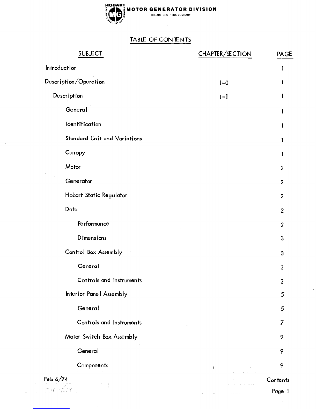
TABLE OF CONTENTS
SUBJECT
CHAPTER/SECTION
PAGE
Introduction
Description/Operation
Description
General
Identification
Standard Unit and Variations
Canopy
Motor
Generator
Hobart Static Regulator
Data
Performance
Dimensions
Control Box Assembly
General
Controls and Instruments
Interior Pane I Assembly
General
Controls and Instruments
Motor Switch Box Assembly
Genera I
Components
1-O
l-1
I
Fe b 6/‘74
Contents
Page 1
FOBART
I
z
“0
B . B ,,d-
;MOTOR GENERATOR DIVISION
QD
:
2
HOBART BROTHERS COMPANY
TABLE OF CONTENTS (CONT’D)
SUBJECT
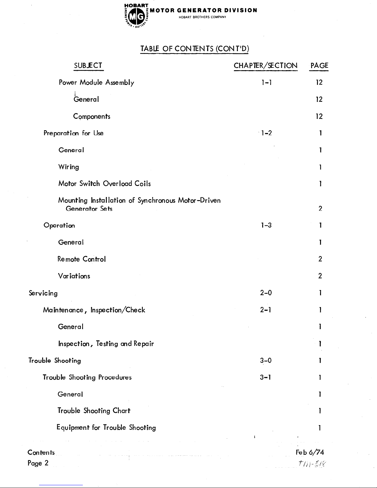
Power Module Assembly
General
Components
Preparation for Use
Genera I
Wiring
Motor Switch Overload Coils
Mounting Installation of Synchronous Motor-Driven
Generator Sets
Operation
Genera I
CHAPlER/SECTI,ON
l-l
l-2
l-3
PAGE
12
12
12
1
1
1
1
2
1
1
Remote Control
Variations
Servicing
Maintenance, Inspection/Check
Genera I
Inspection, Testing and Repair
Trouble Shooting
Trouble Shooting Procedures
General
Trouble Shooting Chart
Equipment for Trouble Shooting
2-o
2-l
3-O
3-l
2
2
1
1
1
1
1
1
1
1
1
Contents
Page 2
SUBJECT
CHA PTER/SECT ION
PAGE
FOBART
8
5
;MOTOR GENERATOR DIVISION
3
QD
3
HOBART BROTHERS COMPANY
%
4. 8ud
TABLE OF CONTENTS (CONT’D.)
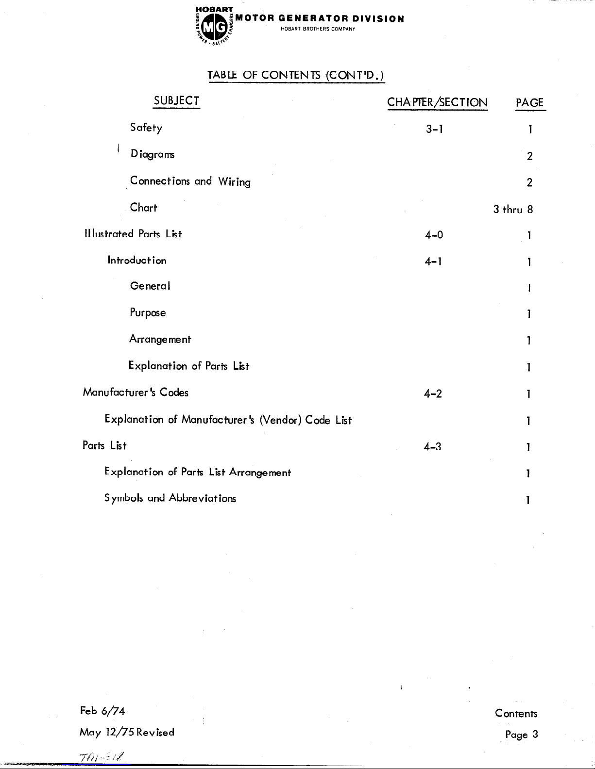
Safety
’ Diagrams
Connections and Wiring
Chart
II lustrated Parts List
Introduction
Genera I
Purpose
Arrangement
Explanation of Parts List
Manufacturer ‘s Codes
Explanation of Manufacturer’s (Vendor) Code List
Parts List
Explanation of Parts List Arrangement
Symbols and Abbreviations
Feb 6/;74
May 12/75 Revised
3-l
4-o
4-l
4-2
4-3
1
2
2
3 thru 8
1
1
1
1
1
1
1
I
Contents
Page 3
Con tents
Page 4
GENERATOR DIVISION
HOBART BROTHERS COMPANY
Fe b 6/74
HOBART
z
J
QD
$MOTOR GENERATOR DIVISION
:
z
HOBART BROTHERS COMPANY
“0
b. B,,\6
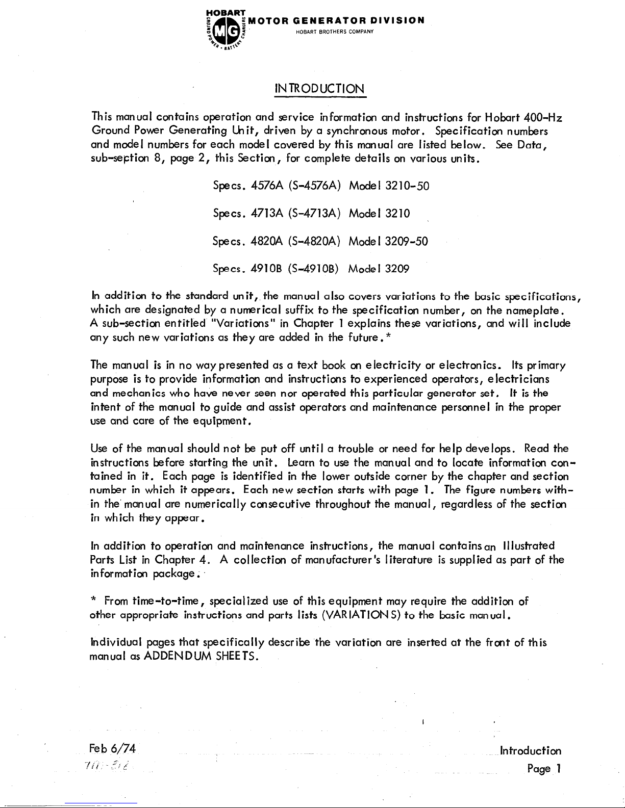
INTRODUCTION
This manual contains operation and service information and instructions for Hobart 400-Hz
Ground Power Generating hit, driven by a synchronous motor. Specification numbers
and model numbers for each model covered by this manual are listed below. See Data,
sub-seption 8, page 2, this Section,
for complete details on various units.
Specs. 4576A (S-4576A) Mode I 32 1 O-50
Specs. 4713A (S-4713A) Model 3210
Specs. 4820A (S-4820A) Mode I 3209-50
Specs. 4910B (S-4910B) Model 3209
In addition to the standard unit,, the manual also covers variations to the basic specifications,
which are designated by a numerical suffix to the specification number, on the nameplate.
A sub-section entitled “Variations” in Chapter 1 explains these variations, and will include
any such new variations as they are added in the future.*
The manual is in no way presented as a text book on electricity or electronics. Its primary
purpose is to provide information and instructions to experienced operators, electricians
and mechanics who have never seen nor operated this particular generator set. It is the
intent of the manual to guide and assist operators and maintenance personnel in the proper
use and care of the equipment.
Use of the manual should not be put off until a trouble or need for help develops. Read the
instructions before starting the unit. Learn to use the manual and to locate information con-
tained in it. Each page is identified in the lower outside corner by the chapter and section
number in which it appears. Each new section starts with page 1. The figure numbers within the’manual are numerically consecutive throughout the manual, regardless of the section
in which they appear.
In addition to operation and maintenance instructions,
the manual containsan Illustrated
Parts List in Chapter 4.
A collection of manufacturer’s I iterature is supplied as part of the
information package;
* From time-to-time, specialized use of this equipment may require the addition of
other appropriate instructions and parts lists (VARIATIONS) to the basic manual.
Individual pages that specifically describe ‘the variation are inserted at the front of this
manual as ADDENDUM SHEETS.
I
Introduction
Page 1

FOBART
e
a
QD
gMOTOR GENERATOR DIVISION
i
HOBART BROTHERS COMPANY
“0
b. ,,,I++
CHAPTER 1. DESCRIPTION/OPERATION
SECTION 1. DESCRIPTION
1.
The 400-Hz AC generator set is a self-contained motor generator set, complete with
all controls, instruments and protective devices necessary for manual or fully automatic
0 ration.
I=
It is designed to utilize standard line power (either 50 or 60 hertz) to
generate power for providing ground service to aircraft, requiring 400-Hz power.
The’ motor and generator rotors are mounted on a common shaft supported at the ends
by ball bearings.
A centrifugal fan is mounted on the shaft between the motor and
generator rotors. In operation,
the fan draws air in axial ly from the outer ends of the
housing, over the rotor and stator windings, and discharges it radially through a duct
at the center of the housing. The housing is of two-piece construction, bolted together
circumferentia-lly at the middle to facilitate removal when necessary for service or repair of enclosed parts.
The entire unit is mounted on a welded structural stee I frame.
2.
Identification
A nameplate bearing SPECS, MODEL and SERIAL numbers of the unit is located
on or near the generator control pane I.
Parts orders or inquiries regarding this
equipment must refer to these numbers. Direct all parts orders and correspondence
to:
MOTOR GENERATOR DIVISION
HOBART BROTHERS COMPANY
TROY , OH IO 45373
U.S.A.
3.
Standard lktit and Variations
As stated above, the standard 400-Hz AC generator is a self-contained, stationary
unit identified by one of the specification (S) numbers listed in lntroductioni
Page 1. Variations to the standard models are identified by VAR. numbers. A
variation provides for motor switch 220-V input power on some models which are
380-volt standard, and a variation provides for mounting the unit on a trailer for
portable use. See the sub-section on VARIATION S, Section 1-3, page 2.
If other variations become available, or if changes are made, new information will
be added at the end of the sections in which the information would normally be located.
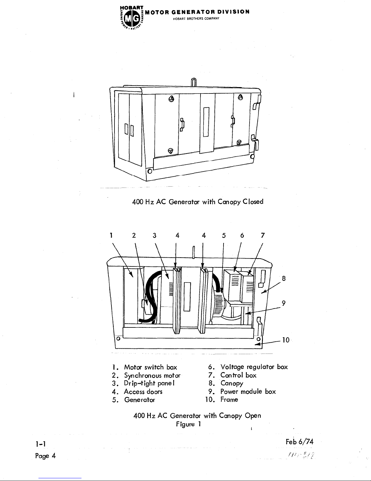
4. Canopy
A sheet metal enclosure, identified as a canopy, provides protection for the electric
motor, generator and electrical controls.
It is equipped with two large (four panels)
hinged doors on each side to provide easy access for service and maintenance. Doors
I
l-l
Page 1

FOBART
I
z
“0
QD
B . II ,+”
gMOTOR GENERATOR DIVISION
2
HOBART BROTHERS COMPANY
at each end of the canopy provide access to the motor switch box on the one end, and the
control box and power module box on the other end.
See Figure 1 for location of these
items .
5. Motor
The drivel motor is 50 or 60 Hz synchronous motor. Field excitation is provided by a rotary
brush less exciter, and is set to provide approximate unity power factor on the input.
6. Generator
The generator is a 3-phase, 4000hertz, synchronous AC generator, or alternator, of the
rotating field type, having output terminals for connection to a 4-wire, grounded neutral,
external circuit. Fie Id excitation is provided by an automatically regulated brush less
rotary exe iter .
7. Hobart Static Regulator
The voltage regulator is designed to maintain the set voltage of the generator within f 1%.
See the regulator manual furnished with this equipment for detailed instructions on installation,
operation and maintenance.
8. Data
A. Performance
Mod. 32 1 O-50
(S-4576A)
Mod. 3210
(S-4713A)
Mod. 3209-50
(S-4820A)
Mod. 3209
(S-4910B)
Motor
Volts
Amperes
Hertz
Phase
Power Factor
RPM
HP
Generator
(2
380
94
50
3
1 .O
1500
75
230/460
154/77
60
3
1.0
1200
75
380
63
50
3
1.0
1500
50
230/460
103/52
60
3
1.0
1200
50
Volts
115/200
Amperes 173
KVA
Duty Cycle 100%
Power Factor 0.8
60
115/200
174
60
48
100%
0.8
400
3
1200
115/200
108
37.5
30
100%
0.8
400
3 ’
1500
115/200
108
37.5
30
100%
0.8
400
3 ’
1200
Fe b 6/74
GENERATOR DIVISION
HOBART BROTHERS COMPANY
B.
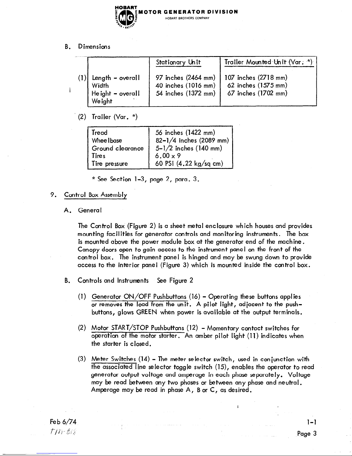
Dimensions
Stationary Unit
Trailer Mounted’Unit- (Var; -*)
(1) Length - overall
97 inches (2464 mm)
107 inches (2718 mm)
I
Width 40 inches (1016 mm)
62 inches (1575 mm)
He ight - overal I
54 inches (1372 mm)
67 inches (1702 mm)
Weight
(2) Trailer (Var. *)
Tread 56 inches (1422 mm)
Whee I base 82-l/4 inches (2089 mm)
Ground clearance
5-l/2 inches (140 mm)
Tires 6.00x9
Tire pressure 60 PSI (4.22 kg/sq‘cm)
* See Section 1-3, page 2, para. 3.
9. Control Box Assembly
A. General
The Control Box (Figure 2) is a sheet metal enclosure which houses and provides
mounting facilities for generator controls and monitoring instruments. The box
is mounted above the power module box at the generator end of the machine.
Canopy doors open to gain access to the instrument panel on the front of the
control box.
The instrument panel is hinged and may be swung down to provide
access to the interior panel (Figure 3) which is mounted inside the control box.
B. Controls and Instruments See Figure 2
(1) Generator ON/OFF Pushbuttons (16) - Operating these buttons applies
or removes the load from the unit. A pilot light, adjacent to the push-
buttons, glows GREEN when power is available at the output terminals.
(2) Motor START/STOP Pushbuttons (12) - Momentary contact switches for
operation of the motor starter.
An amber pilot light (11) indicates when
the starter is closed.
(3) Meter Switches (14) - The meter selector switch, used in conjunction with
the associated line selector toggle switch (15), enables the operator to read
generator output voltage and amperage in each phase separately. Voltage
may be read between any two phases or between any phase and neutral.
Amperage may be read in phase A, B or C, as desired.
l-l
Page 3
rOBART_
e
QD
gMOTOR GENERATOR DIVISION
B
:
z
HOBART BROTHERS COMPANY
“c
b. sa+e
400 Hz AC Generator with Canopy Closed
3
4 5 6 7
8
10
1. Motor switch box
6. Voltage regulator box
2. Synchronous motor
7. Control box
3. Drip-tight panel
8. Canopy
4. Access doors
9. Power module box
5. Generator
10. Frame
400 Hz AC Generator with Canopy Open
Figure 1
I
l-l
Feb
6/74
Page 4
-tr-c p;
FOBART
:
;MOTOR GENERATOR DIVISION
‘:
“0
QD
=i
HOBART BROTHERS COMPANY
%
z
.9. ,q,1”
(4)
(5)
I
(6)
(7)
(8)
(9)
(10)
(11)
(12)
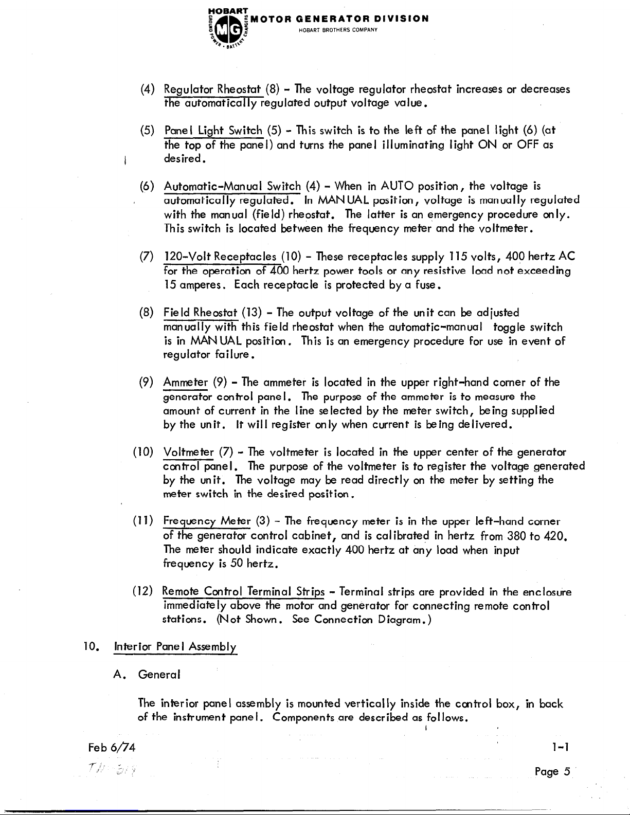
Regulator Rheostat (8) - The voltage regulator rheostat increases or decreases
the automatically regulated output voltage value.
Panel Light Switch (5) - Th is switch is to the left of the panel light (6) (at
the top of the panel) and turns the pane I illuminating light ON or OFF as
desired.
Automatic-Manual Switch (4) - When in AUTO position, the voltage is
automatically regulated.
In MANUAL position, voltage is manually regulated
with the manual (field) rheostat. The latter is an emergency procedure only.
This switch is located between the frequency meter and the voltmeter.
120-Volt Receptacles (10) - These receptacles supply 115 volts, 400 hertz AC
for the operation of 400 hertz power tools or any resistive load not exceeding
15 amperes. Each receptacle is protected by a fuse.
Field Rheostat (13) - Th e output voltage of the unit can be adjusted
manually with this field rheostat when the automatic-manual toggle switch
is in MANUAL position,
This is an emergency procedure for use in event of
regulator failure.
Ammeter (9) - Th e ammeter is located in the upper right-hand corner of the
generator control pane I.
The purpose of the ammeter is to measure the
amount of current in the line selected by the meter switch, being supplied
by the unit. It will register only when current is being delivered.
Voltmeter (7) - The voltmeter is located in the upper center of the generator
control pane I. The purpose of the voltmeter is to register the voltage generated
by the unit. The voltage may be read directly on the meter by setting the
meter switch in the desired position.
Frequency Meter (3) - The frequency meter is in the upper left-hand corner
of the generator control cabinet, and is calibrated in hertz from 380 to 420.
The meter should indicate exactly 400 hertz at any load when input
frequency is 50 hertz.
Remote Control Terminal Strips -
Terminal strips are provided in the enclosure
immediately above the motor and generator for connecting remote control
stations. (Not Shown.
See Connection Diagram.)
10.
Interior Pane I Assembly
A. General
The interior panel assembly is mounted vertically inside the control box, in back
of the instrument pane I.
Components are described as follows.
I
Feb 6/74
l-l
Page 5
FOBART
e
s
QD
iMOTOR GENERATOR DIVISION
d
HOBART BROTHERS COMPANY
%
4F,. s,,l’*’
1. 3 45 6 7 8
9 2 1
k
53
0
10
II0
16
t-:
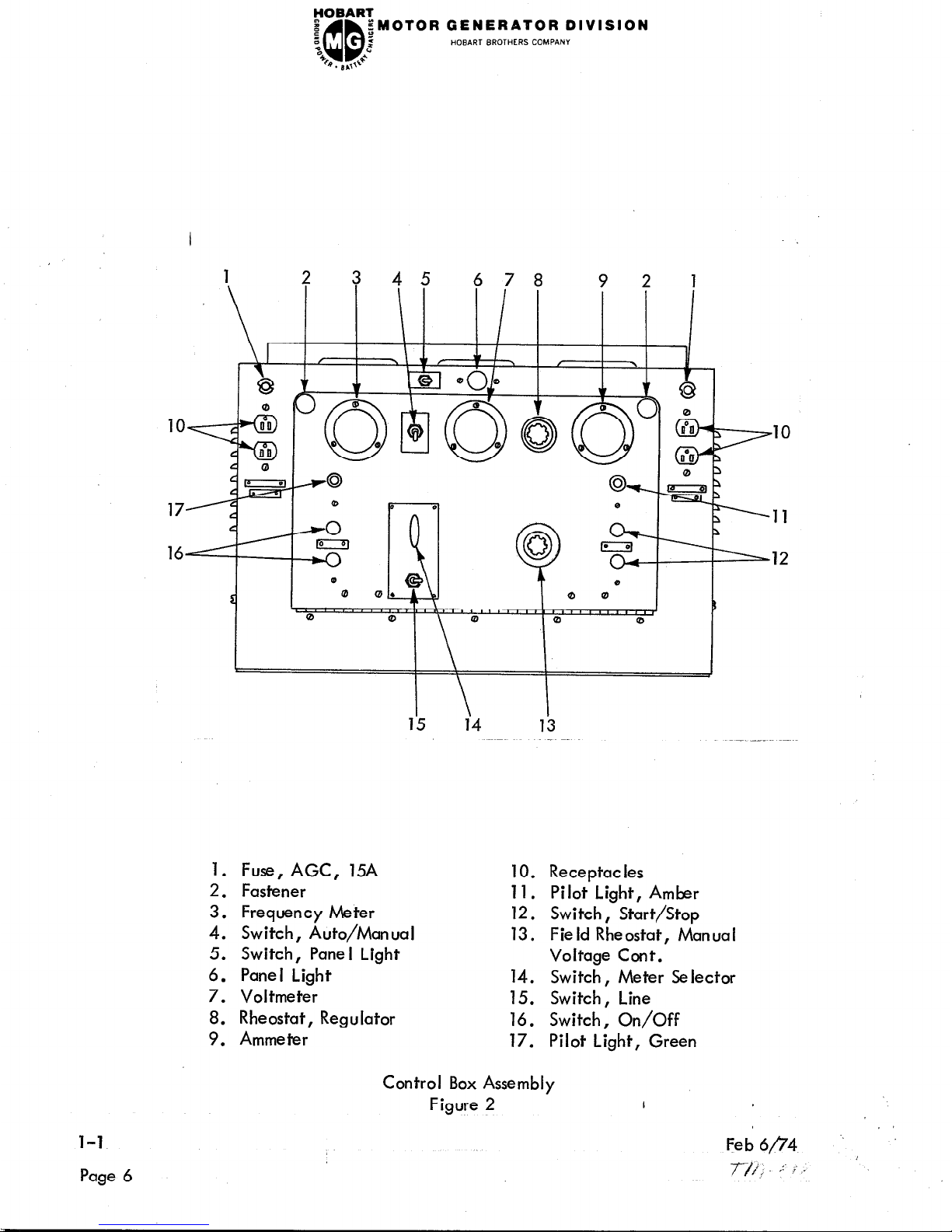
1. Fuse, AGC, 15A
10. Receptacles
2. Fastener
11. Pilot Light, Amber
3. Frequency Meter
12. Switch, Start/Stop
4. Switch, Auto/Manual
13. Field Rheostat, Manual
5. Switch, Pane I Light
Voltage Cont.
6. Panel Light
14. Switch, Meter Selector
7. Voltmeter
15. Switch, Line
8. Rheostat, Regulator
16. Switch, On/Off
9. Ammeter
17. Pilot Light, Green
,lO
,ll
.12
l-l
Page 6
Control Box Assembly
Figure 2
I
rOBART_
I
z
QD
:MOTOR GENERATOR DIVISION
:
“0
E
HOBART BROTHERS COMPANY
48
6
9. 8.0
B. Controls and Instruments
(1)
, (2)
(3)
(4)
(5)
(6)
(7)
(8)
(9)
Rectifier, Load Contactor (10) - Furnishes direct current to the operating
coil of the load contactor.
Relay, Time De lay (11) (hdervoltage Timer) - This relay is set for a 5-second
time delay in the undervoltage circuit.
This relay provides time de lay when
abnormal loads are encountered for a short period of time. If an undervoltage
persists for a period longer than 5 seconds,
the main contactor circuit will be
opened.
Manual Range Limiting Resistor (6) - This 250-ohm resistor is set to limit
voltage when the AUTO-MAN UAL Switch is in MAN UAL position, and the
manual rheostat is turned all the way clockwise.
Undervoltage Relay (2) - This relay is set to close its set of contacts when
the line-to-neutral voltage falls to 93-103 volts; this is equivalent to a
line-to-line output voltage of 161-178.5 volts. The closing of these contacts
energize a 5-seccnd time delay relay switch Gee (2) above], which in turn
opens the main contactor, protecting the load from effects of low voltage.
hderfrequency Relay (4) - Th
ese contacts open if the frequency drops to
approximately 360 hertz and ret lose when the frequency recovers to 375 hertz.
The purpose of this relay is to open the main contactor and protect the load
from the effects of operating at too low a frequency.
Overvoltage Relay (1) - Th
is relay has a normally closed set of contacts
which open if the voltage exceeds 130 to 134 volts, line-to-neutral, or
225 to 232 volts, I ine-to-l ine .
This opens the main contactor to remove the
load from the generator.
Plug Interlock Relay (13) - The 28 volts DC from the aircraft, through
terminals E and F and Neutral causes the interlock relay to close, as well
as the contactor in the aircraft. With the interlock relay closed, power is
maintained to the rectifier, holding the contactor closed when the ON button
is released.
Plug Interlock Switch (or Test Bank Switch) (12) - This toggle switch should be
OFF when feeding an aircraft with control leads on E and F, or ON for feeding
a load bank or other non-aircraft load without the plug interlock system.
Current Limiting Resistor (3) - This 1000ohm, 250watt resistor is in series
with the plug interlock relay to limit the amount of load current drawn through
the plug interlock relay contacts, in case phase “C” of the load contactor
does not close when the generator “ON ” pushbutton is actuated.
I
l-l
Page 7
YOBART
e
QQ
EMOTOR GENERATOR DIVISION
s
:
z
HOBART BROTHERS COMPANY
3
b . n ,,+**
2
3
4
5
6 7
I
I
I
t
0
I
t
I
A
13
9 12
I r
II IO 9
8
J
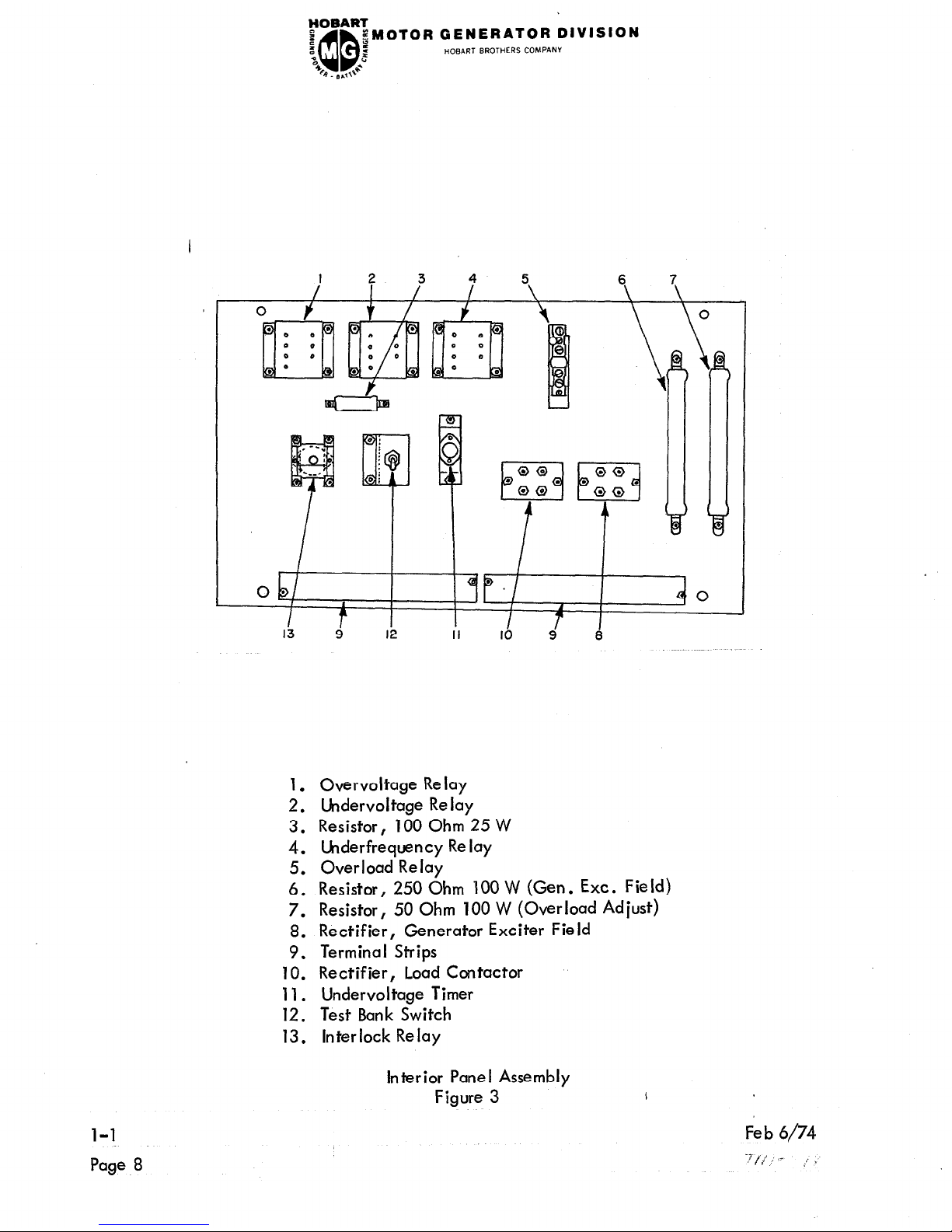
1. Overvoltage Relay
2. Undervoltage Relay
3. Resistor, 100 Ohm 25 W
4. Underfrequency Relay
5. Overload Relay
6. Resistor, 250 Ohm 100 W (Gen . Ext. Field)
7. Resistor, 50 Ohm 100 W (Overload Adjust)
8. Rectifier, Generator Exciter Field
9. Terminal Strips
10. Rectifier, Load Contactor
11. Undervoltage Timer
12. Test Bank Switch
13. Interlock Relay
l-l
Page 8
Interior Panel Assembly
Figure 3
FOBART
e
QQ
;MOTOR GENERATOR DIVISION
I
z
e
HOBART BROTHERS COMPAN”
“0
s. B,,+a
(10)
(11)
I
Overload Relay (OL) (5) - This thermally operated relay serves to protect the
generator set from the effects of any induced overload (grounding or shorting
of exciter or generator, or exce,ssive load).
Overload Adjustment Resistor (7) - This resistor, connected in parallel with
the overload relay, serves to regulate the tripping time of the overload relay.
It is set to trip the overload relay at 25% overload in 4-5 minutes.
If nuisance
overload tripping becomes a problem, trip point may be increased by moving
the resistor adjusting slide away from the end to which the jumper wire is
attached.
11.
Motor Switch Box Assembly
A. General
The motor switch furnishes primary control for the drive motor.
It is located in the
motor end of the canopy, with doors opening to gain access to the motor switch box.
N OTE :
The motor STOP/START
pushbutton switch is located on the control
panel at the opposite end of the unit. The non-manual components
for stop/start, time delay, voltage changeover, etc., are located
on a panel in the motor switch box assembly.
B. Components
(1)
(2)
(3)
Transformer
- This transformer (3) reduces input line voltage from 380-V AC to
115-V AC for operation of the time delay relays, motor switch coils, control
relay, etc.
A 5-ampere fuse (15) protects the 115-V AC control circuit. The transformer
is functional at all times when input power is connected to the input terminals
and the overload relay (4) contacts are closed.
?TP%
- The control relay (9) applies power to the “main” motor switch
COI w en t e START pushbutton is pressed. The relay also by-passes the
START and STOP pushbutton switches to prevent the relatively high switch-coil
currents from passing through them. All power for operation of switches, timers,
etc., must pass through this relay.
Main Motor Switch - The “main” switch (6) consists of three pairs of stationary
contacts and three pairs of movable contacts. Movable contacts are clamp
mounted on a bearing supported shaft.
A core is attached to the shaft, so that
when the magnetic switch coil is energized,
the center of the coil.
it attracts the core and pulls it into
to close the contacts.
The core is thus moved to rotate the shaft sufficiently
The contacts are held in the closed position as long as
the switch coil is energized.
When the coil circui,t is broken, the contacts
l-l
Page 9
FOBART
D
;
n
“0
QQ
;MOTOR GENERATOR DIVISION
:
2
HOBART BROTHERS COMPANY
B , B ,,J
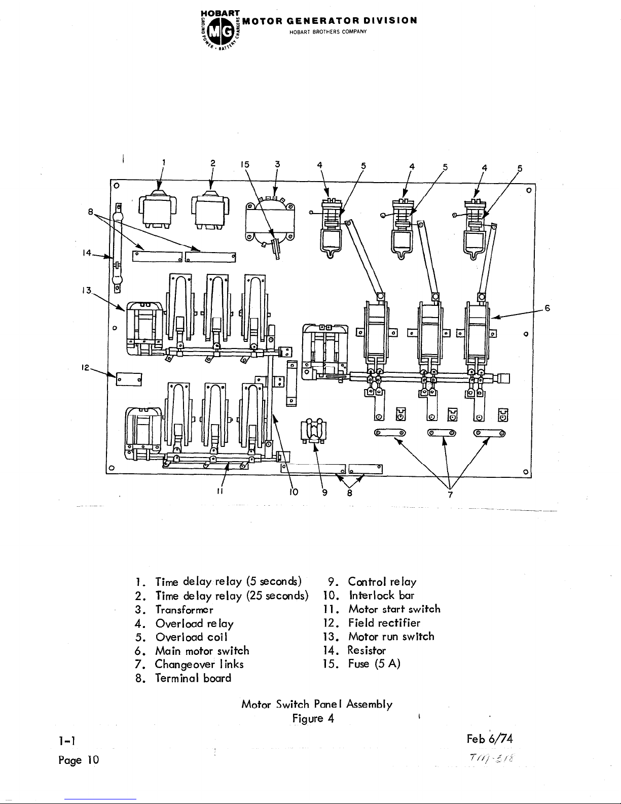
ll
1. Time delay relay (5 seconds) 9. Control relay
2. Time delay relay (25 seconds)
10. Interlock bar
3.
Transformer
11. Motor start switch
4.
Overload relay
12. Field rectifier
5.
Overload coil
13. Motor run switch
6.
Main motor switch
14. Resistor
7.
Changeover links
15. Fuse (5 A)
8. Terminal board
1-l
Page 10
Motor Switch Panel
Figure 4
Assembly
I
Feb $74
T/i,/ .,‘/;
-6
IVISION
FOBART
e
,QQ
EMOTOR GENERATOR D
z
2
HOBART BROTHERS COMPANY
3
2
4
0. B&l>
‘a
are opened immediately by gravity and spring loading. Stationary contacts
are equipped with blowout coils and arc shields to “blowout”, “dampen”,
and minimize arcing which results from opening the contacts. A small set
of contacts mounted on the “main ” contact shaft are closed when the “main ”
contacts are closed.
These contacts apply a holding current to the switch
I
coil circuitry and allow the START switch button to be released after the
main switch closes.
(4) Motor “Start” Switch
- The motor “start” switch (11) is very similar to the
“main” motor switch (6) described above.
Mechanical and electrical operating
characteristics are the same. The “start” switch is energized to close at the
same time the “main” switch is closed to provide a “wye” starting connection
to the motor‘stator windings.
(5)
Time Delay Relay (25 Second) - This is a double-pole, double-throw,
120-V AC relay (2). It has an adjustable time delay range of from 5 seccnds
to 50 seconds. For this application it is adjusted for a time delay of 25 seconds
between energization of the coil and actuation of the contacts. The coil is
energized as soon as the control relay (9) contacts close. After a delay of
25 seconds, the time delay relay functions to open the “start” switch (11)
and close the “run” switch (13). At the same time it supplies power to the
5-second time delay relay (1)
and also supplies 115-V AC power to the
voltage regulator for flashing the generator field. The 25-second delay
allows the motor to reach operating speed.
(6) Time De lay Re lay (5 Seconds) - This re lay (1)
is identical to the time delay
relay (2) described above , except it is adjusted for a 5-second time delay.
It is energized at the same time the “run” switch is closed. The function
of this relay is to connect 115-V AC to the field application relay and
disconnect flashing current from the generator field, 5 seconds after the
“run” switch closes.
(7) Motor Run Switch - The motor “run” switch is identical to the “start” switch.
After the motor reaches operating speed with the stator windings in “wye”
connection, the “start” switch opens and the “run” switch closes to connect
the motor stator windings in
“delta” connection for synchronous running.
The “main” switch remains closed during this operation.
(8) Start-Run Interlock Bar - The interlock bar is designed to mechanically pre-
vent the motor “start” switch and “run” switch from closing or being closed at
the same time.
(9) Field Rectifier - This rectifier converts 115-V alternating current to direct
current for excitation of the motor exciter fields. The rectifier becomes
functional five seconds after the motor run switch is closed.
I
Feb 6/74
l-l
71,; -5 : [;
Page 11
(10)
(11)
(12)
(13)
(14)
FOBARZ
z
QQ
$MOTOR GENERATOR DIVISION
s
2
z
HOBART BROTHERS COMPANY
“0
B . B ,‘,++
Overload Relay - These solenoid operated, dashpot type relays (4) protect the
motor against overload.
Under a continuous overload condition, the coils
(5), which carry the motor input current, provide a magnetic force sufficiently
strong to pull the dashpot plunger upward against the retaining force of the
dashpot piston to OPEN the relay contacts which supply input power to the
trsformer (3). Thus, all operating power is removed from the controls and
all normally open switches return to OPEN position.
The resistive force of the dashpot on the movement of the plunger prevents
nuisance tripping of the relay contacts when the motor is overloaded for short
periods of time,
such as in starting, etc.
Overload Coil - These coils (5), which are connected in series with input power
cables, provide magnetic force for operating the overload plungers.
Changeover Links - The connector links (7) provide a means of quickly changing
the motor stator connections for other applications.
Terminal Board - Four terminal boards (8) provide connection facilities for
electrical components interconnecting wiring.
Resistor - This 250-ohm, loo-watt resistor (14) functions to discharge voltage
induced in the revolving fields when the motor starts.
12. Power Module Assembly
A.
B.
l-l
Page 12
Genera I
The power module assembly provides a terminal point for the output power terminals,
and input power junction box.
It supports the following components as described
below.
Components
(1)
(2)
(3)
Current Transformers (Ammeter) (7) - These transformers are used together with
the ammeter to indicate the amount of load current at any time.
Current Transformers (Line Drop Compensation) (9) - These transformers are
used with the regulator for line drop compensation.
Load Contactor (8) - The contactor connects and disconnects the generator
and the load. The contactor is furnished DC voltage by the rectifier on the
inter ior pane I .
The generator ON/OFF switch (item 16, Figure 2) on the
control pane I, controls the opening and closing of the contactor.
Fed 6/74
YOBARI
e
a
QQ
;MOTOR GENERATOR DIVISION
,,oB,WT BROTHERS COMPANY
z
I
CI
b . @ ,,k-
3 4 5
6
7
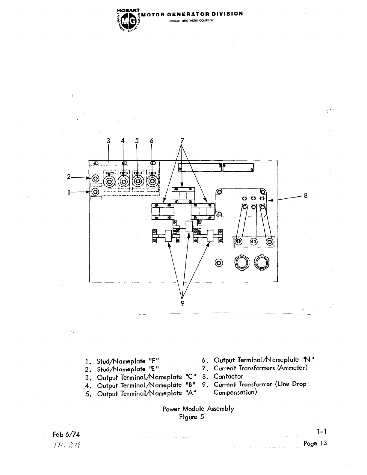
1. Studfiameplate “F”
6. Output Terminal~ameplate “N ”
2. Stud/hJameplate “E” 7. Current Transformers (Ammeter)
3. Output Terminalbameplate “C” 8. Contactor
4. Output TerminaI/t\lameplcite
“B” 9. Current Transformer (Line Drop
5. Output Terminalfiameplate “A” C om-pensation)
Power Module Assembly
Figure 5
I
1-l
Page 13
FOBART
@
QQ
2MOTOR GENERATOR DIVISION
z
2
2
HOBART BROTHERS COMPANY
“0
b . I ,,+*
(4) Output Power Terminals: Phase “A” (6)
Phase “B” (5)
Phase “C” (4)
Neutral “N” (3)
Stud “F” (2)
Stud “E ” (1)
l-l
Feb 6p4
Page 14
. -:
,/ -,.;,* :
FOBART
e
z
“0
% . B ,,+”
Genera I
1.
When installing or storing this ground power unit, avoid locations exposed to high
huTidity or dust. Moisture condenses on generator parts and electrical controls, caus-
ing corrosion which can seriously affect operation and efficiency. Dust and dirt cause
needless extra wear on al I moving parts.
2. Wiring
The incoming power must be 3=phase, and should pass through a fused disconnect switch
ahead of the motor switch input terminals. Make certain that overload coils, motor
switch link position, and control transformer connections are correct for the input
voltage used.
;MOTOR GENERATOR DIVISION
s
z
QQ
SECTION 2. PREPARATION FOR USE
HOBART BROTHERS COMPANY
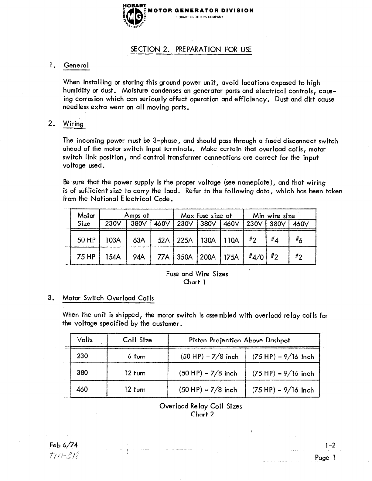
Be sure that the power supply is the proper voltage (see nameplate), and that wiring
is of sufficient size to carry the load. Refer to the following data, which has been taken
from the National E lectrical Code.
Fuse and Wire Sizes
Chart 1
3. Motor Switch Overload Coils
When the unit is shipped, the motor switch is assembled with overload relay coils for
the voltage specified by the customer.
Overload Relay Coil Sizes
Chart 2
l-2
Page 1
FOBART
I
f
“0
B . B ,+”
CAUTION: IF A 3-CONDUCTOR, RUBBER-COVERED, INPUT POWER CABLE
IS USED, IT IS NECESSARY TO GROUND THE EQUIPMENT WITH
A WIRE OF MINIMAL COMPARATIVE SIZE TO THE WIRE- IN THE
INPUT POWER CABLE. THIS WIRE MAY BE BARE OR INSULATED
AND OF ANY COLOR, BUT IT MUST MAKE GOOD ELECTRICAL
CONTACT WITH A METALLIC PART OF THE GENERATOR FRAME,
I
OF THE SHEET METAL CABINET, OR OF THE CONTROL BOX AND
A WATER PIPE OR THE FUSED DISCONNECT SWITCH BOX.
WHEN 4-CONDUCTOR, RUBBER-COVERED CABLE IS USED, THE
GROUNDING WIRE MUST BE GREEN IN COLOR. WHEN FLEXIBLE
ARMORED CABLE OR CONDUIT IS REQUIRED BY LOCAL CODES,
INSTALL IT IN SUCH A MANNER THAT ADEQUATE GROUNDING
OF THE EQUIPMENT IS INSmED.
WITH THE MACHINE FRAME GROMDED, THE OPERATOR IS
ALWAYS ASSURED MAXIMUM PROTECTION EVEN IN THE UN-
LIKELY EVENT OF INSULATION FAILURE OR ACCIDENTAL
GROUNDING OF THE POWER SUPPLY.
;MOTOR GENERATOR DIVISION
z
z
QQ
HOBART BROTHERS COMPANY
4. Mounting Installation of Synchronous Motor-Driven Generator Sets
A. General
No “hard and fast” rules for mounting the generator set can be given because
they may vary, depending upon the users requirements and facilities. Common
sense must be used in all installations to achieve a firm mounting which is free
from vibration and which does not place undue stress on the skid (mounting frame)
and motor-generator.
Mounting Cautions
B.
Before recommending how to mount the generator set, we believe you should
first be cautioned about how NOT to mount it.
CAUTION: (l)DO NOT BOLT THE MACHINE TO AN U\IEVEN FLOOR,
PAD, OR PEDESTAL. THIS CAN CAUSE DAMAGING
STRESSES IN THE FRAME AND MOTOR-GENERATOR.
(2)D0 NOT SET (AND OPERATE) THE MACHINE LOOSELY ON
AN UNEVEN SURFACE. THIS CAN RESULT IN AN UN-
STABLE THREE-POINT SUSPENSION AND CAUSE VIBRATION.
Most all cases of vibration are caused by mounting the generator set on an uneven
floor surface.
l-2
Page 2
I
Feb 6/74
,7;l’j .3 “2
$iOBARl
z
a
‘c
‘c,
C. Recommended Mounting Instructions
qMOTOR GENERATOR DIVISION
2
QQ
d
0. @*1x
HOBART BROTHERS COMPAN”
(1) Mounting surface -
is the mounting surface. Whether the machine is mounted on a cement
floor, or on a pedestal, the mounting surface should be even and smooth
so that the full length of the skid can contact the cement.
The single most important thing in generator mounting
I
(2) Pad mounting -
between the skid and mounting surface in all installations.
Resilient pads placed between the skid and the floor may help to compensate
for slight unevenness in the mounting surface, and also insulate the skid
from-floor to reduce vibration . .
with or without bolts from skid to floor.
(3) Leveling pads - An alternate method to the plain pad installation described
above is one involving the use of self-contained leveling mounts such
as “Unisorb Level-Rites” or equivalent. These mounts will compensate
for a greater degree of floor unevenness than plain insulating pads.
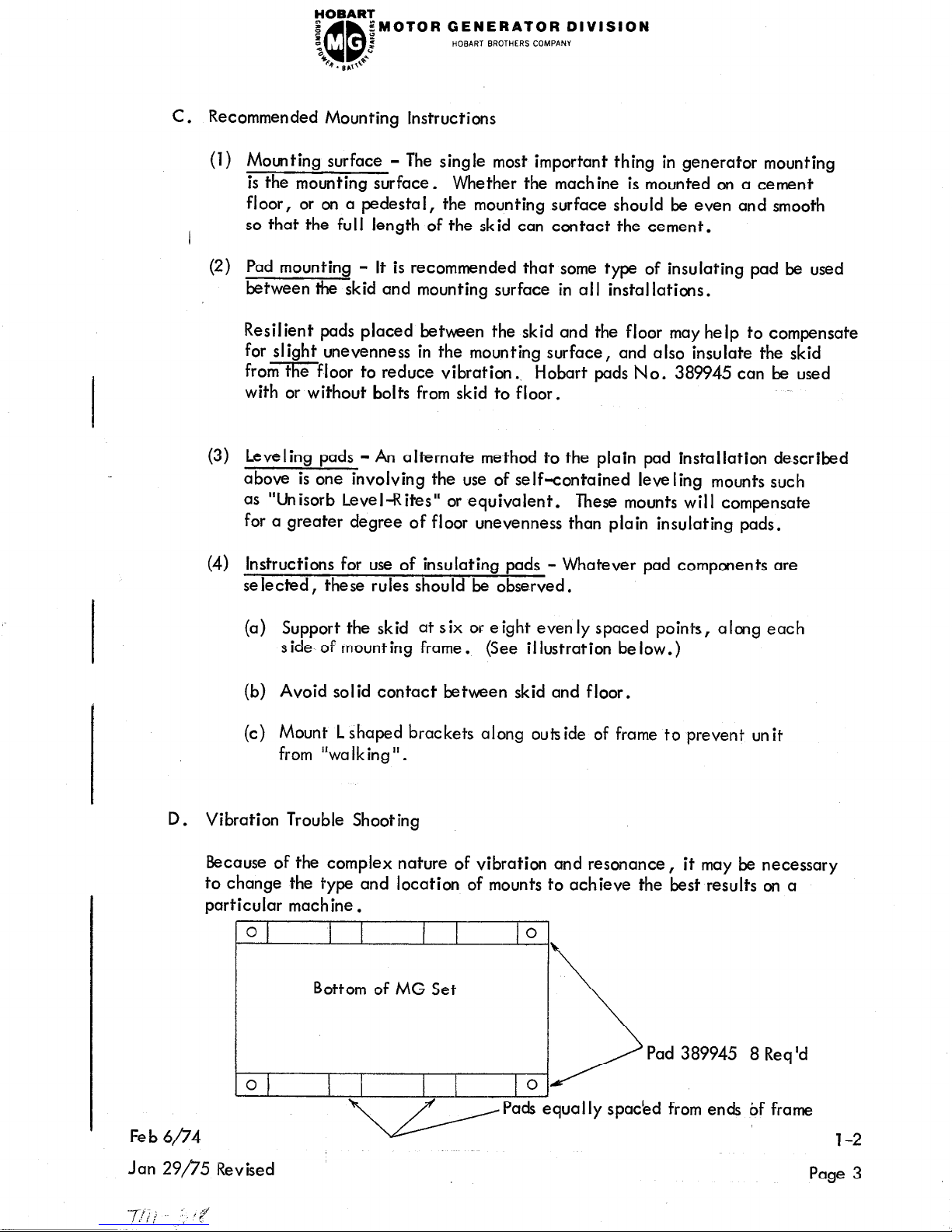
(4) Instructions for use of insulating pads - Whatever pad components are
selected, these rules should be observed.
It is recommended that some type of insulating pad be used
Hobart pads No. 389945 can be used
(a) Support the skid at six or eight evenly spaced points, along each
side of mounting frame.
(b) Avoid solid contact between skid and floor.
(c) Mount Lshaped b
from “walking”.
D. Vibration Trouble Shooting
Because of the complex nature of vibration and resonance, it may be necessary
to change the type and location of mounts to achieve the best results on a
particular machine.
rackets along outside of frame to prevent unit
(See illustration below.)
Pad 389945 8 Req ‘d
Fe b 6/74
Jan 29/?‘5 Revised
Pads equally spaced from ends of frame
l-2
Page 3
FOBART
z
QQ
;MOTOR GENERATOR DIVISION
z
5
HOBART BROTHERS COMPANY
“ss.
2
64
c
. BAT+
l-2
Page 4
Feb ~$74
FOBART
e
z
“0
44@. g,,++*
1. General
Determine that the machine is properly installed (see Section 1, sub-section 12, para.
11 2 and 3). Connect a 3-phase load to terminals N, A, B, C, E and F at the upper
left-hand side of the power module panel.
service. Also see Section 2, sub-section 4, l-2, page 2.
A. Starting
To start the unit, place the motor circuit breaker, if so equipped, in ON position,
momentarily push the motor START button (12, Fig. 2) and release it. The armature
should rotate in the direction indicated by the arrow on the housing.
not, wait until the motor is up to speed, stop the machine (see paragraph D below),
and reverse any two of the incoming power lines. This change will cause the
armature to rotate in the correct direction. Armature rotation should be in a
counterclockwise direction when the operator is facing the generator control
pane I, where the START-STOP push buttons are located.
$MOTOR GENERATOR DIVISION
:
z
QQ
SECTION 3, OPERATION
HOBART BROTHERS COMPANY
E and Fare interlock leads for aircraft
If it does
With the motor running ,
to full speed, adjust the voltage regulator rheostat until the voltmeter indicates
120 volts line to neutral.
B. Applying Load
Press the generator ON button to apply the load. The GREEN pilot light will
glow when the generator output contactor is closed. The voltage regulator will
automatically maintain the set voltage.
The voltage between any two phases (A-B, B-C, C-A) or line to neutral can be
read directly on the voltmeter by setting the meter selector switch and associated
toggle switch to the desired position.
The current on any phase can be read directly on the ammeter by placing the
meter selector switch on the desired phase (A, B, or C).
C. To Disconnect Load
To stop the supply of current to the load, push the generator OFF pushbutton.
D. To Stop Motor
the AMBER pilot light will glow. After the machine is up
Disconnect generator load, if any, push the motor STOP pushbutton momentarily,
and release it.
I
l-3
Page 1
FOBART
e
QQ
;MOTOR GENERATOR DIVISION
t
2
HOBART BROTHERS COMPANY
“0
2
b . B ,,,J-
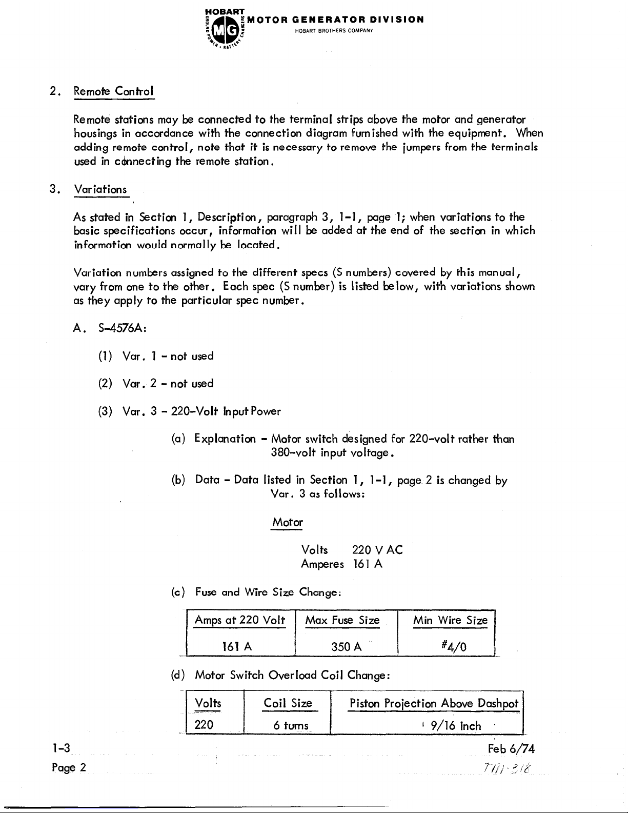
2. Remote Control
Remote stations may be connected to the terminal strips above the motor and generator
housings in accordance with the connection diagram furnished with the equipment. When
adding remote control, note that it is necessary to remove the jumpers from the terminals
used in cknecting the remote station.
3.
Variations
As stated in Section 1, Description, paragraph 3, l-l, page 1; when variations to the
basic specifications occur,
information will be added at the end of the section in which
information would normally be located.
Variation numbers assigned to the different specs (S numbers) covered by this manual,
vary from one to the other.
Each spec (S number) is listed below, with variations shown
as they apply to the particular spec number.
A. S-4576A:
(1) Var. 1 - not used
(2) Var. 2 - not used
(3) Var. 3 - 220-Volt Input Power
(a) Explanation
- Motor switch designed for 220-volt rather than
380-volt input voltage.
(b) Data - Data listed in Section 1, l-1, page 2 is changed by
Var. 3 as follows:
Motor
Volts
220 v AC
Amperes 161 A
(c) Fuse and Wire Size Change:
Amps at 220 Volt Max Fuse Size
Min Wire Size
161 A 350 A #4/o
(d) Motor Switch Overload Coil Change:
Volts
Coil Size
_Y
Piston Projection Above Dashpot
220
6 turns
1 9/16 inch p
l-3
Feb
6/74
Page 2
7-/j)
2, ;k
 Loading...