

Hobart 3100 Owner’s Manual

MODEL
3100
&
3100C
STACKING SLICER
ML-104493 3100
ML-104494
3100e
\ H
'?@!,~.~
701
S. RIDGE AVENUE
TROY, OHIO 45374-0001
T I
Form 19234 Rev. B (11-98)
TABLE OF CONTENTS
GENERAL 3
INSTALLATION 3
UNPACKING 3
ASSEMBLy 5
TEST SLICER OPERATION 10
ELECTRiCAL 10
TRAII\JING 10
OPERATION
SAFETY
BEFORE FIRST USE
CONTROLS ;
SELECTING LAYOUT OPTIONS 13
THE KEYPAD 15
BASIC LAYOUTS - RECTANGULAR TRAY 16
MULTIPLE LAYOUTS - RECTANGULAR TRAY 18
BASIC LAYOUTS - ROUND PLATTER 19
MULTIPLE LAYOUTS - ROUND PLATTER 20
SANDWICH PACKAGE LAYOUTS 20
EXAMPLES
SLICING 22
MANUAL
AUTOMATIC 23
11
11
11
12
21
22
..
RECLAMPING '
REPROGRAMMING FACTORY PRESET VALUES 25
CLEANII\JG 27
MAINTENANCE 30
SHARPENING THE KNIFE 30
LAYOUT PROBLEMS
LUBRICATIOI\I
WEAR ADJUSTMENT
© HOBART CORPORATION 1993
-2-
24
32
32
32

Installation, Operation and Care of
MODEL 3100
& 3100C STACKING SLICER
SAVE THESE INSTRUCTIONS FOR FUTURE USE
GENERAL
Your Hobart Model 3100 or
Model
31
The slicer is
the Model 3100 Slicer, the slices can be deposited
slices are deposited
For best results with the Hobart stacking slicer, your staff must be carefully instructed
operation and care of the slicer
slicer.
31
DOC
is equipped with a conveyor. A Model 3100 Slicer cannot be field converted to a Model
DOC.
Both models feature two slicing speeds: 40 or
an
electronically controlled, programmable system for manual or automatic slicing.
on
31
DOC
Stacking Slicer is to be used to slice meats and cheeses only.
60
strokes per minute.
on
a tray or round platter.
the conveyor, tray, or round platter.
in
accordance with this manual. Only trained staff should operate the
On
Model
31
DOC,
in
On
the
the
) Before operating your stacking slicer for the first time, read this manual through carefully. It gives
details of correct installation, operation and care, and will show you how to make the most of your
slicing system.
Improper installation, electrical or otherwise, incorrect operation, improper use, alterations to the
machine or use of anything other than Hobart original spare parts and accessories, use of any
lubrications, etc., not recommended by Hobart, or repairs carried out by
void the warranty.
an
unauthorized agent may
INSTALLATION
UNPACKING
It will require two people to lift the slicer from the box. Lift slicer using the two bars on either side of
the machine and the bar
Immediately after unpacking the slicer, check for possible shipping damage. If the slicer is found to
be damaged, save the packaging material and contact the carrier within 15 days of delivery.
in
front (Fig. 1).
Prior to installation, verify that the electrical service agrees with the specification
plate which is located
on
the right side under the carriage
-3-
..
on
the machine data

I PL-22038]
Fig. 1
Ensure the correct accessories are included
MODEL 3100
Standard Accessories
Transport System
Depositor
Interleaf Strip Dispenser (NS)
Round Platter
Rectangular Platter (NS)
Sharpener
(2) Cleaning Brushes
Scrap Collector (NS)
Optional Accessories
Foot Switch (t\lS)
Chipping/Shaving Depositor
Sandwich Package
31
00-31
OOC
Table (NS)
31
00-31
OOC
Shelf (NS)
Fork
(2) Peels (for lifting sliced
product from conveyor
belt or tray) (NS)
Round Peel (for lifting sliced
product from round platter) (NS)
in
the box (Fig. 2). (NS=t\lot Shown)
MODEL 3100C
Standard Accessories
Transport System
Depositor
Interleaf Strip Dispenser (NS)
Conveyor System (NS)
Foot Switch (NS)
Sharpener
Round Platter
Rectangular Platter (NS)
(2) Cleaning Brushes
Handle Assembly (NS)
(for mounting conveyor)
Scrap Collector
(t\lS)
Optional Accessories
Chipping/Shaving Depositor
Sandwich Package
31
00-31
OOC
Table (NS)
31
00-31
OOC
Shelf (NS)
Fork
(2) Peels (for lifting sliced
product from conveyor
belt or tray) (t\lS)
Round Peel (for lifting sliced
product from round platter) (NS)
-4-
SHARPENER
CLEANING
BRUSHES
---I
'PL:~22039
1_
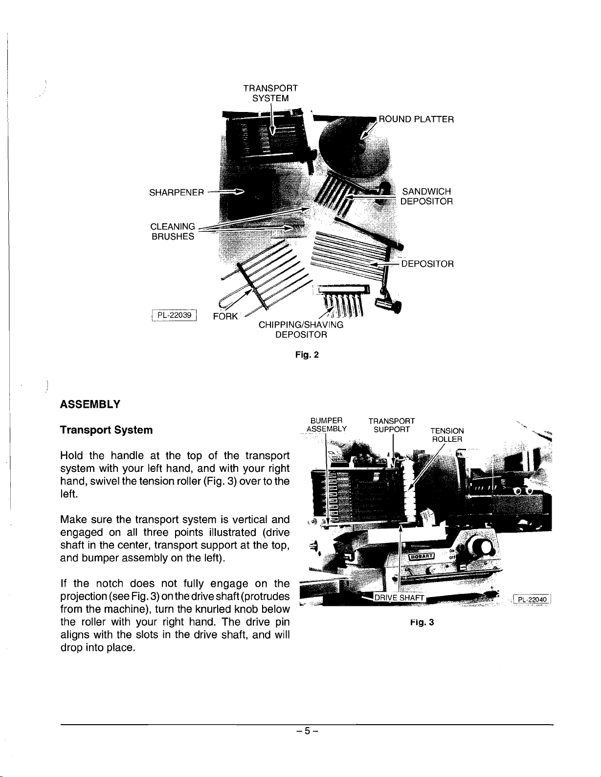
ASSEMBLY
Transport System
Hold the handle at the top of the transport
system with your left hand, and with your right
hand, swivel the tension roller (Fig.
left.
Make sure the transport system
engaged
shaft
and bumper assembly
If the notch does not fully engage on the
projection (see
from the machine), turn the knurled knob below
the roller with your right hand. The drive pin
aligns with the slots
drop into place.
on
all three points illustrated (drive
in
the center, transport support at the top,
Fig.
3)
on
in
J
CHIPPING/SHAVING
DEPOSITOR
3)
over to the
is
vertical and
on
the left).
the drive shaft (protrudes
the drive shaft, and will
Fig. 2
-
•.
".:."'.\'\.\
/;!J \ ':-
,~l
\
TRANSPORT
SUPPORT
;JDRivE'SHA,,~
•.
Fig. 3
,J,lll1;":
·,l~~]
'
.....
-5-
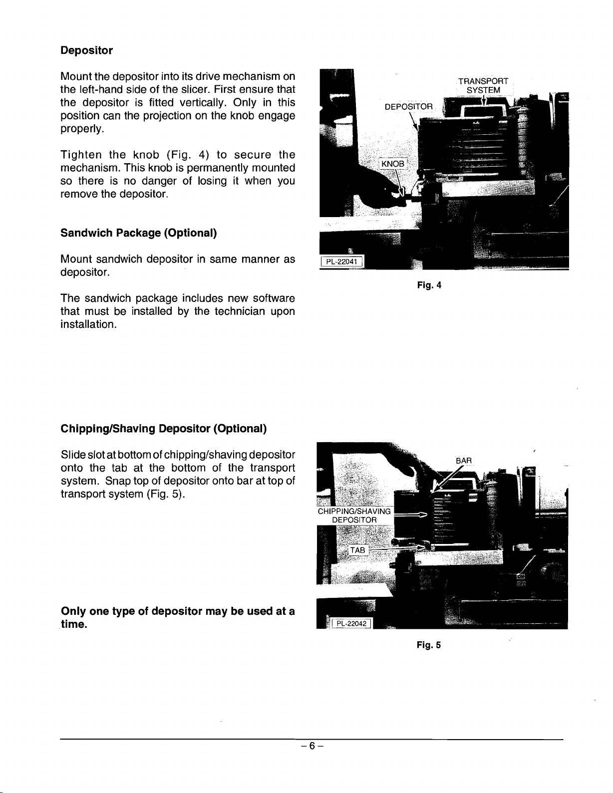
Depositor
Mount the depositor into its drive mechanism
on
the left-hand side of the slicer. First ensure that
the depositor is fitted vertically. Only
position
can
the projection
on
the knob engage
in
this
properly.
Tighten
the knob (Fig. 4) to
secure
the
mechanism. This knob is permanently mounted
so
there
is
no
danger of losing it when
you
remove the depositor.
Sandwich Package (Optional)
Mount sandwich depositor
in
same manner as
depositor.
The sandwich package includes new software
that must
be
installed
by
the technician upon
installation.
Fig. 4
Chipping/Shaving Depositor (Optional)
Slide slot at bottom of chipping/shaving depositor
onto the tab at the bottom of the transport
system. Snap top of depositor onto bar at top of
transport system (Fig. 5).
Only one type of depositor may be used at a
time.
Fig. 5
-6-
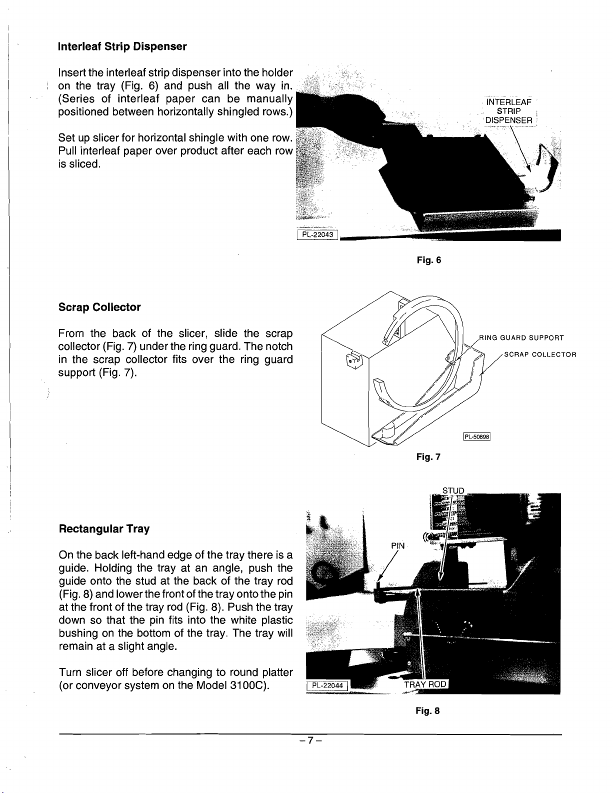
Interleaf Strip Dispenser
Insert the interleaf strip dispenser into the holder
on
the tray (Fig.
(Series of interleaf paper can be manually
positioned between horizontally shingled rows.)
up
Set
Pull irrterleaf paper over product after each row
is
Scrap Collector
slicer for horizontal shingle with one
sliced.
6)
and push all the way in.
row.
I PL-22043 I
Fig. 6
INTERLEAF
STRIP
DISPENSER
.
....
,T'.\
..
' ''
. .
II..
!;-t"c,::\.
fr··;it~)
~;
.• ' -"c'
..
',r
..
'-","
".i,
.
,j
..•••.•'..••.•
.
From the back of the slicer, slide the scrap
7)
collector (Fig.
in
the scrap collector fits over the ring guard
support (Fig. 7).
Rectangular Tray
On
the back left-hand edge of the tray there
guide. Holding the tray at
guide onto the stud at the back of the tray
(Fig.
8)
and lower the front of the tray onto the pin
at the front of the tray
down so that the pin fits into the white plastic
bushing
remain at a slight angle.
on
under the ring guard. The notch
is
an
angle, push the
rod
rod
(Fig. 8). Push the tray
the bottom of the tray. The tray will
a
Fig. 7
RING
IPL-50898 I
GUARD
SUPPORT
Turn slicer off before changing to round platter
on
(or conveyor system
the Model
31
DOC).
Fig. 8
-7-
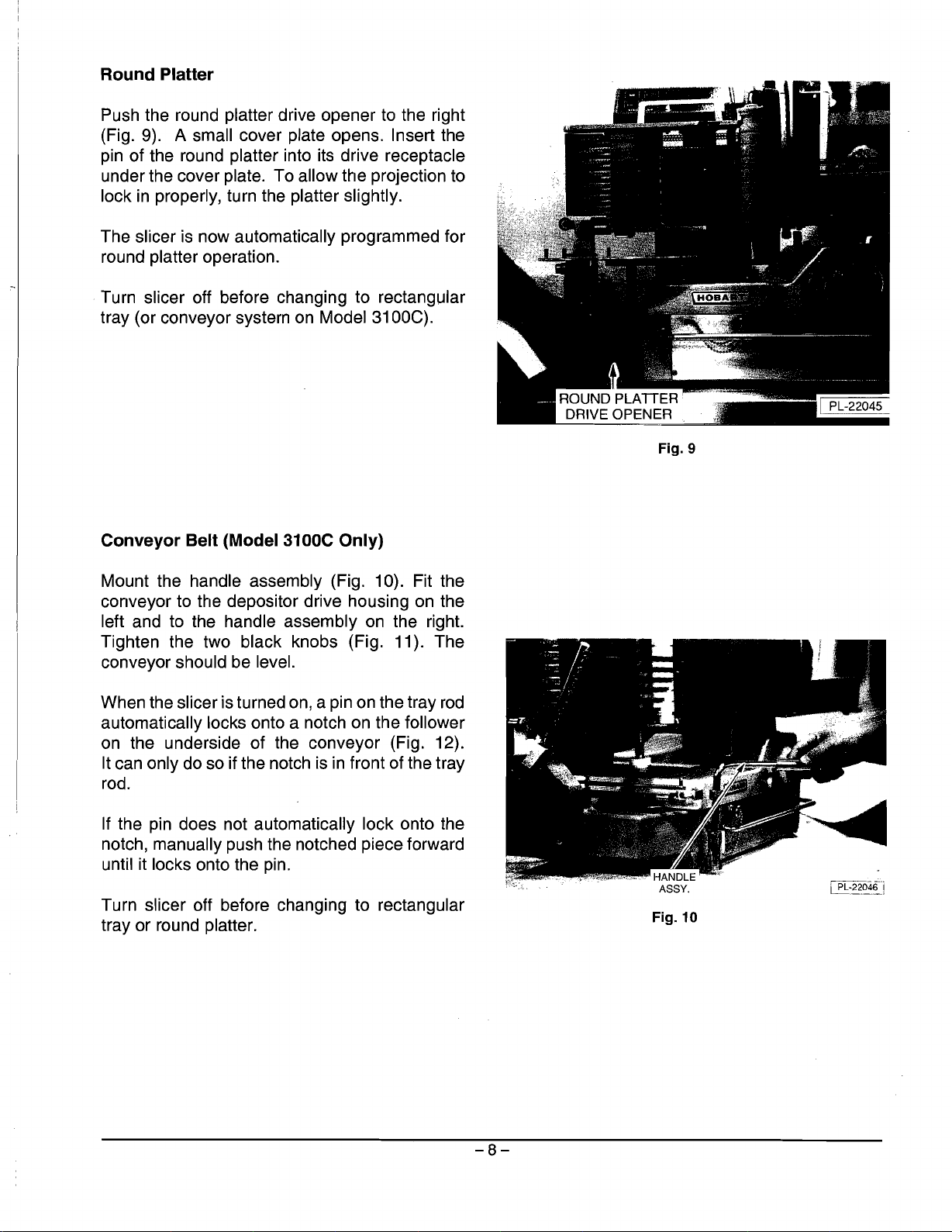
Round Platter
Push the round platter drive opener to the right
(Fig. 9). A small cover plate opens. Insert the
pin of the round platter into its drive receptacle
under the cover plate. To allow
lock
in
properly, turn the platter slightly.
the projection to
The slicer is now automatically programmed for
round platter operation.
Turn slicer off before changing to rectangular
tray (or conveyor system on Model 3100C).
~'
III
ROUND
DRIVE OPENER
PLAlTER
Fig. 9
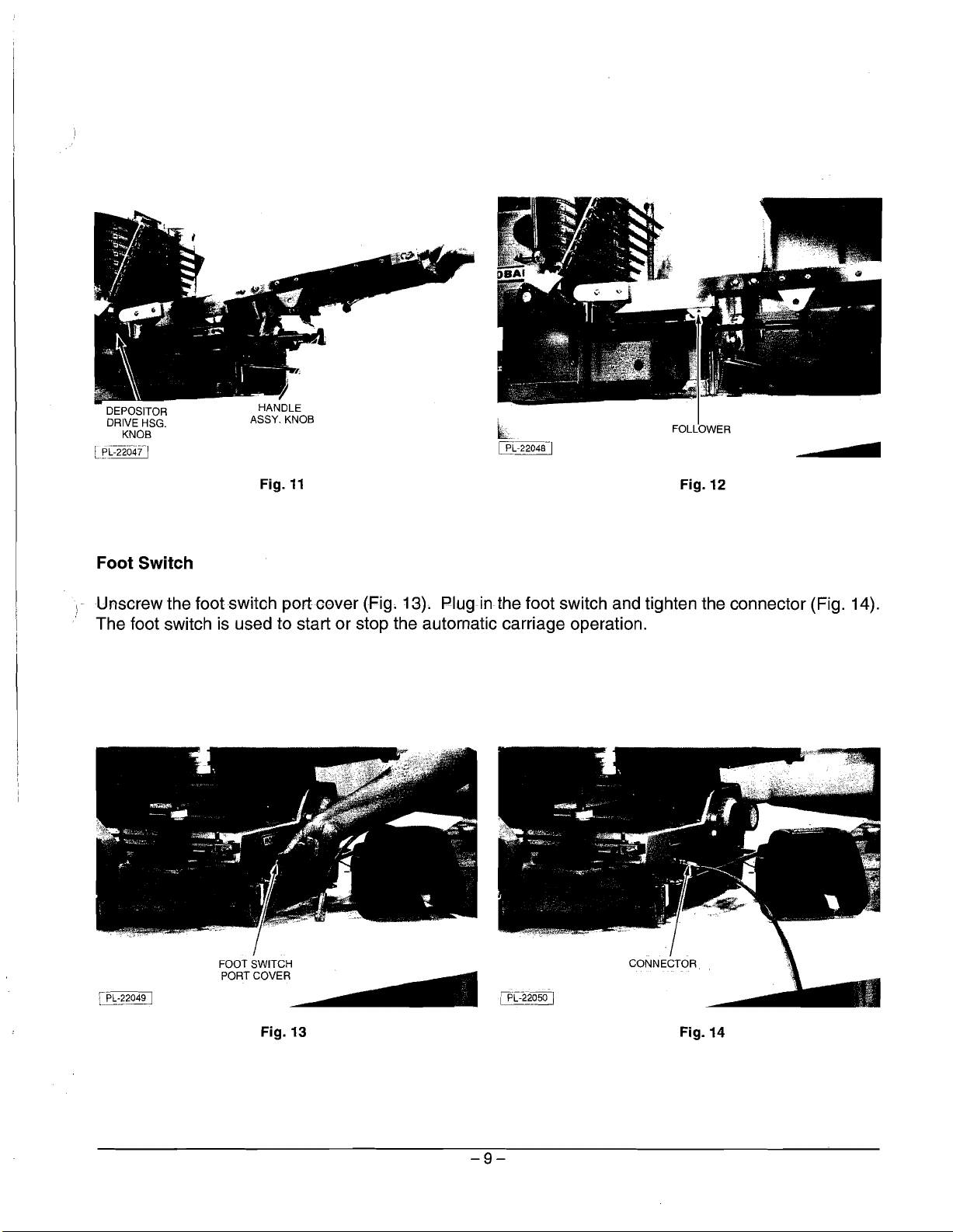
Conveyor Belt (Model 3100C Only)
Mount the handle assembly (Fig. 10). Fit the
conveyor to the depositor drive housing on the
left and to the handle assembly on the right.
Tighten the two black knobs (Fig. 11). The
conveyor should be level.
When the slicer is turned on, a pin on the tray
rod
automatically locks onto a notch on the follower
on the underside of the conveyor (Fig. 12).
It can only do so if the notch is
in
front of the tray
rod.
If the pin does not automatically lock onto the
notch, manually push the notched piece forward
until it locks onto the pin.
Turn slicer off before changing to rectangular
tray or round platter.
ili:~186-i
Fig. 10
-8-
DEPOSITOR
DRIVE HSG.
KNOB
[1'L-=-22047"/
Foot Switch
Fig.
11
~L
lli
-22048-1
FOLLOWER
Fig.
12
•
i" Unscrew the footswitoh port"oever (Fig. 13). Plug
in
the foot switch and tighten the connector (Fig. 14).
, The foot switch is used to start or stop the automatic carriage operation.
CONNECTOR
lPL:~204~
FOOT SWITCH
PORTCOVER~
Fig.
13
1P[:2-2_~
Fig.
14
-9-

TEST SLICER OPERATION
Once assembly is completed, test
ELECTRICAL
WARNING:
THIS MACHINE
all
functions.
IS
PROVIDED WITH A THREE-PRONG GROUNDING PLUG.
IMPERATIVE THAT THE OUTLET TO WHICH THIS PLUG
GROUNDED.
IF
THE RECEPTACLE
IS
NOT THE PROPER GROUNDING TYPE, CONTACT
ELECTRICIAN.
TRAINING
All staff who will
training
is
available through your local Hobart representative.
be
operating this slicer must receive in-depth training
IS
CONNECTED
in
the use of the slicer. This
BE
PROPERLY
IT
IS
AN
-10-
 Loading...