

查询HMC270MS8G供应商
14
MICROWAVE CORPORATION
Typical Applications
The HMC270MS8G is ideal for
DC - 8.0 GHz applications:
• CATV
• MMDS & WirelessLAN
• Wireless Local Loop
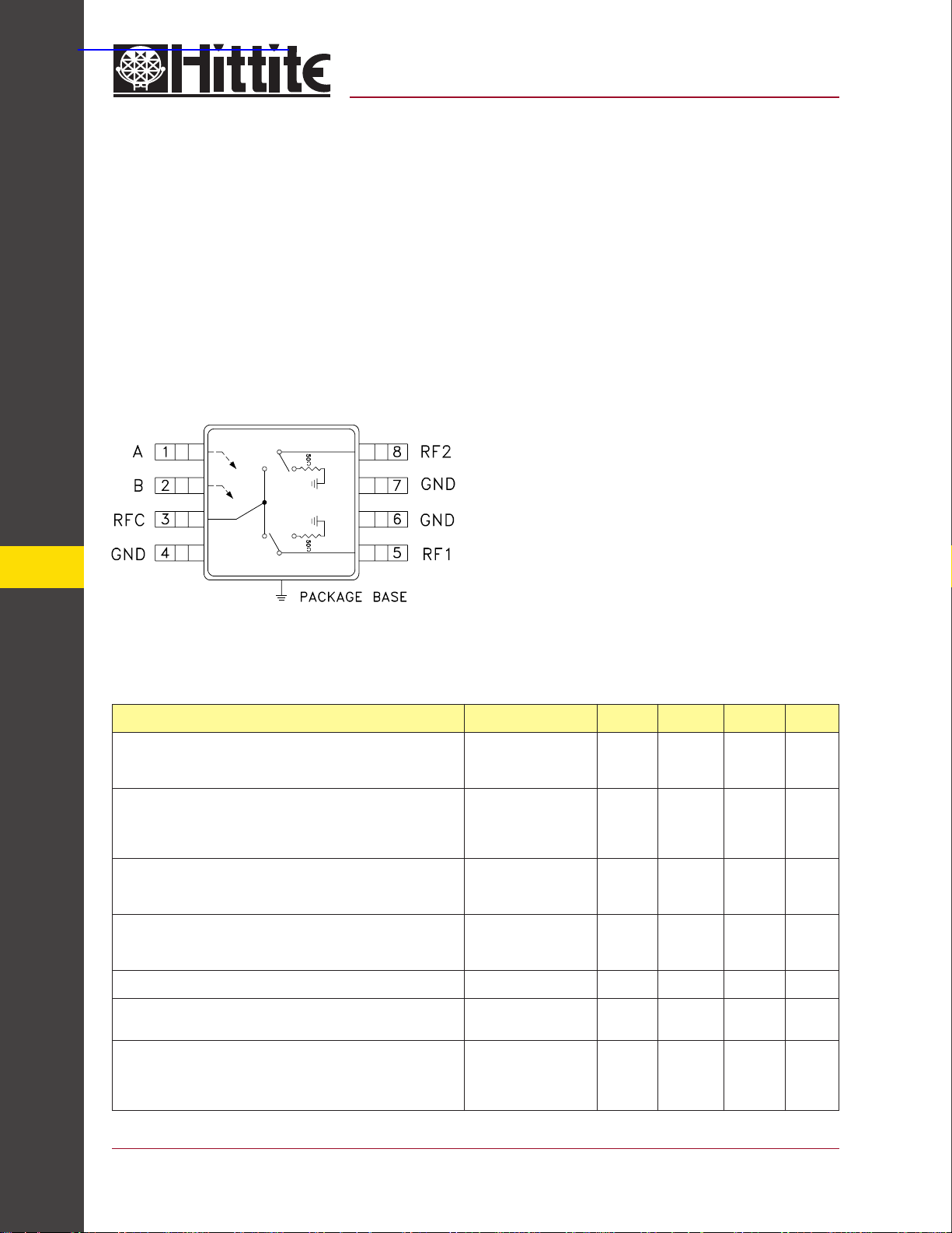
Functional Diagram
v02.0701
HMC270MS8G
GaAs MMIC SPDT SWITCH
NON-REFLECTIVE, DC - 8.0 GHz
Features
Broadband Performance: DC - 8 GHz
Very High Isolation: 45 dB @ 6 GHz
Non-Refl ective Design
Low Cost MSOP-8 Package: 14.8 mm
General Description
The HMC270MS8G is a broadband non-refl ective
GaAs SPDT switch in an 8 lead MSOP grounded
base surface mount plastic package. Covering
DC to 8 GHz, the switch offers excellent isolation
from 70 to 35 dB. The negative control voltage of
-5 volts allows operation down to DC. If positive
control is required along with high isolation, see
the DC to 3.5 GHz HMC284MS8G non-refl ective
SPDT.
2
Electrical Specifi cations, T
Parameter Frequency Min. Typ. Max. Units
Insertion Loss
Isolation
SWITCHES - SMT
Return Loss “On State”
Return Loss RF1, RF2 “Off State”
Input Power for 1 dB Compression 0.5 - 8.0 GHz 20 23 dBm
Input third Order Intercept
(Two-Tone Input Power = +7 dBm Each Tone)
Switching Characteristics DC - 8.0 GHz
tRISE, tFALL (10/90% RF)
tON, tOFF (50% CTL to 10/90% RF)
= +25° C, With 0/-5V Control, 50 Ohm system
A
DC - 2.0 GHz
DC - 6.0 GHz
DC - 8.0 GHz
DC - 2.0 GHz
DC - 4.0 GHz
DC - 6.0 GHz
DC - 8.0 GHz
DC - 2.0 GHz
DC - 6.0 GHz
DC - 8.0 GHz
DC - 2.0 GHz
DC - 6.0 GHz
DC - 8.0 GHz
0.5 - 8.0 GHz 33 36 dBm
43
42
37
28
11
9
7
15
13
10
0.8
1.0
1.5
48
47
45
33
14
12
10
20
18
15
20
50
1.2
1.7
2.4
dB
dB
dB
dB
dB
dB
dB
dB
dB
dB
dB
dB
dB
ns
ns
14 - 146
For price, delivery, and to place orders, please contact Hittite Microwave Corporation:
12 Elizabeth Drive, Chelmsford, MA 01824 Phone: 978-250-3343 Fax: 978-250-3373
Order Online at www.hittite.com
v02.0701
HMC270MS8G
MICROWAVE CORPORATION
GaAs MMIC SPDT SWITCH
NON-REFLECTIVE, DC - 8.0 GHz
GaAs MMIC SUB-HARMONICALLY PUMPED MIXER 17 - 25 GHz
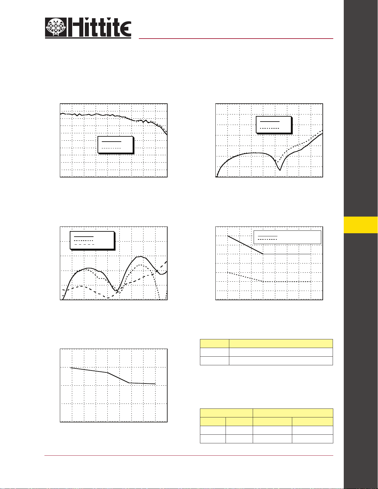
Insertion Loss Isolation
0
-1
-2
-3
INSERTION LOSS (dB)
-4
-5
0123456789
FREQUENCY (GHz)
RF1
RF2
Return Loss
0
RFC
-5
-10
-15
RETURN LOSS (dB)
-20
-25
0123456789
RF1,2 On
RF1,2 Off
FREQUENCY (GHz)
0
-10
-20
-30
-40
ISOLATION (dB)
-50
-60
-70
0123456789
FREQUENCY (GHz)
RF1
RF2
0.1 and 1 dB Input Compression Point
26
25
24
23
22
21
20
COMPRESSION POINT (dBm)
19
18
0123456789
FREQUENCY (GHz)
1 dB Compression Point
0.1 dB Compression Point
14
Input Third Order Intercept Point
45
40
35
30
THIRD ORDER INTERCEPT (dBm)
25
0123456789
FREQUENCY (GHz)
For price, delivery, and to place orders, please contact Hittite Microwave Corporation:
12 Elizabeth Drive, Chelmsford, MA 01824 Phone: 978-250-3343 Fax: 978-250-3373
Order Online at www.hittite.com
Control Voltages
State Bias Condition
Low 0 to -0.2V @ 10 uA Typ.
High -5V @ 35 uA Typ. to -7V @ 100 uA Typ (±0.5 Vdc)
RFC, RF1, & RF2 should be at <100 mV DC potential.
Otherwise, DC blocking capacitors are recommended.
Choose value for lowest frequency of operation.
Do not “HOT” switch power levels >+13 dBm (Vctl = 0/-5Vdc)
Truth Table
Control Input Signal Path State
A B RFC to RF1 RFC to RF2
High Low ON OFF
Low High OFF ON
SWITCHES - SMT
14 - 147

MICROWAVE CORPORATION
v02.0701
Absolute Maximum Ratings
Max RF Input Power, Vctl = -5V +24 dBm
Control Voltage Range +0.5 to -7.5 Vdc
Storage Temperature -65 to +150 °C
Operating Temperature -40 to +85 °C
Outline Drawing
HMC270MS8G
GaAs MMIC SPDT SWITCH
NON-REFLECTIVE, DC - 8.0 GHz
14
SWITCHES - SMT
Suggested Driver Circuit for HMC270MS8G
NOTES:
1. PACKAGE BODY MATERIAL: LOW STRESS INJECTION MOLDED
PLASTIC SILICA AND SILICON IMPREGNATED.
2. LEADFRAME MATERIAL: COPPER ALLOY
3. LEADFRAME PLATING: Sn/Pb SOLDER
4. DIMENSIONS ARE IN INCHES [MILLIMETERS].
5. DIMENSION DOES NOT INCLUDE MOLDFLASH OF 0.15mm PER SIDE.
6. DIMENSION DOES NOT INCLUDE MOLDFLASH OF 0.25mm PER SIDE.
7. ALL GROUND LEADS AND GROUND PADDLE MUST BE SOLDERED
TO PCB RF GROUND.
14 - 148
Simple driver using inexpensive standard logic ICs provides fast switching using minimum DC current while translating from standard positive voltage TTL or CMOS logic to negative voltage GaAs IC logic.
For price, delivery, and to place orders, please contact Hittite Microwave Corporation:
12 Elizabeth Drive, Chelmsford, MA 01824 Phone: 978-250-3343 Fax: 978-250-3373
Order Online at www.hittite.com

MICROWAVE CORPORATION
v02.0701
Eval Board Layout (Top View)
HMC270MS8G
GaAs MMIC SPDT SWITCH
NON-REFLECTIVE, DC - 8.0 GHz
*R1 = R2 = 100 Ohm.
These are optional resistors.
List of Materials
Item Description
J1 - J3 PC Mount SMA Connector
J4 - J5 DC Pin
Chip Capacitor, 0402 Pkg, choose value for lowest
C1 - C3
R1 - R2 100 Ohm Resistor, 0402 Pkg.
U1 HMC270MS8G SPDT Switch
frequency of operation. PCBs are provided with 100
~ 300 pF capacitors. User may jumper capacitor
mounting gaps on PCB to allow operation to “DC”.
The circuit board used in the fi nal application should
be generated with proper RF circuit design techniques.
Signal lines at the RF ports should have 50 ohm impedance and the package ground leads and exposed ground
paddle should be connected directly to the ground plane
similar to that shown above. The evaluation circuit board
shown above is available from Hittite Microwave Corporation upon request.
14
SWITCHES - SMT
PCB* 102807 Evaluation PCB 2.0” x 2.6”
* Circuit Board Material: Rogers 4350
For price, delivery, and to place orders, please contact Hittite Microwave Corporation:
12 Elizabeth Drive, Chelmsford, MA 01824 Phone: 978-250-3343 Fax: 978-250-3373
Order Online at www.hittite.com
14 - 149
 Loading...