

Page 1
MICROWAVE CORPORATION
GaAs MMIC SMT SINGLE BALANCED MIXER 1.7 - 3.5 GHz
HMC285
4
MIXERS
FEBRUARY 2001
Features
NO EXTERNAL COMPONENTS REQUIRED
LO/RF ISOLATION: 32 dB
INPUT IP3: +20 dBm
IDEAL FOR MMDS & W-CDMA
V00.0700
General Description
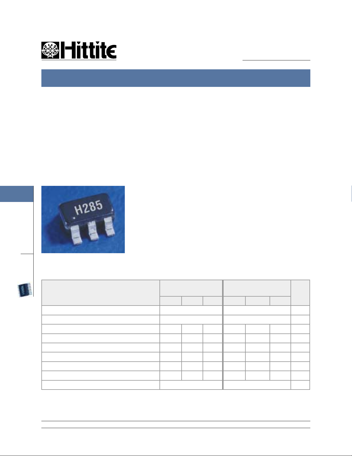
The HMC285 is an ultra miniature single balanced mixer in a 6 lead plastic surface mount
SOT26 package. This passive MMIC mixer is
constructed of GaAs Schottky diodes and a
novel planar transformer balun on the chip. The
RF port is balanced via the MMIC balun while the
LO port is connected directly to the diodes. The
device can be used as an up or downconverter
for PCS, W-CDMA, 2.4 ISM, or MMDS applications. The consistent MMIC performance will
improve system operation without the need for
external components. The SOT26 package is
the smallest footprint available for a complete
single-balanced mixer, 0.118” x 0.118” (3.0mm
x 3.0mm).
Guaranteed Perf ormance, As a Function of IF Frequency, -40 to +85 deg C
SMT
Parameter
Frequency Range, RF & LO 2 - 3.5 1.7 - 2.8 GHz
Frequency Range, IF DC - 900 DC - 900 MHz
Conversion Loss 9 11 9.5 11.5 dB
Noise F igure (SSB) 9 11 9.5 11.5 dB
LO to RF Isolation 20 30 25 35 dB
LO to IF Isolation 11 20 14 20 dB
IP3 (Input) 17 21 16 20 dBm
1 dB Gain Compression (Input) 7 11 6 10 dBm
Local Oscillator Drive Level (Typical) 7 to 15 7 to 15 dBm
Note: The IF frequency may be used from 400 - 800 MHz if the RF/LO frequency range is 1.5 - 2.7 GHz with an LO
drive = +10dBm. Increasing the LO drive increases the bandwidth for all frequency schemes.
12 Elizabeth Drive, Chelmsford, MA 01824 Phone: 978-250-3343 Fax: 978-250-3373 Web Site: www.hittite.com
4 - 164
LO = +10 dBm
IF = 100 MHz
Min. Typ. Max. Min. Typ. Max.
LO = +10 dBm
IF = 400 MHz
Units
Page 2
MICROWAVE CORPORATION
HMC285 SMT SINGLE-BALANCED MIXER 1.7 - 3.5 GHz
HMC285
V00.0700
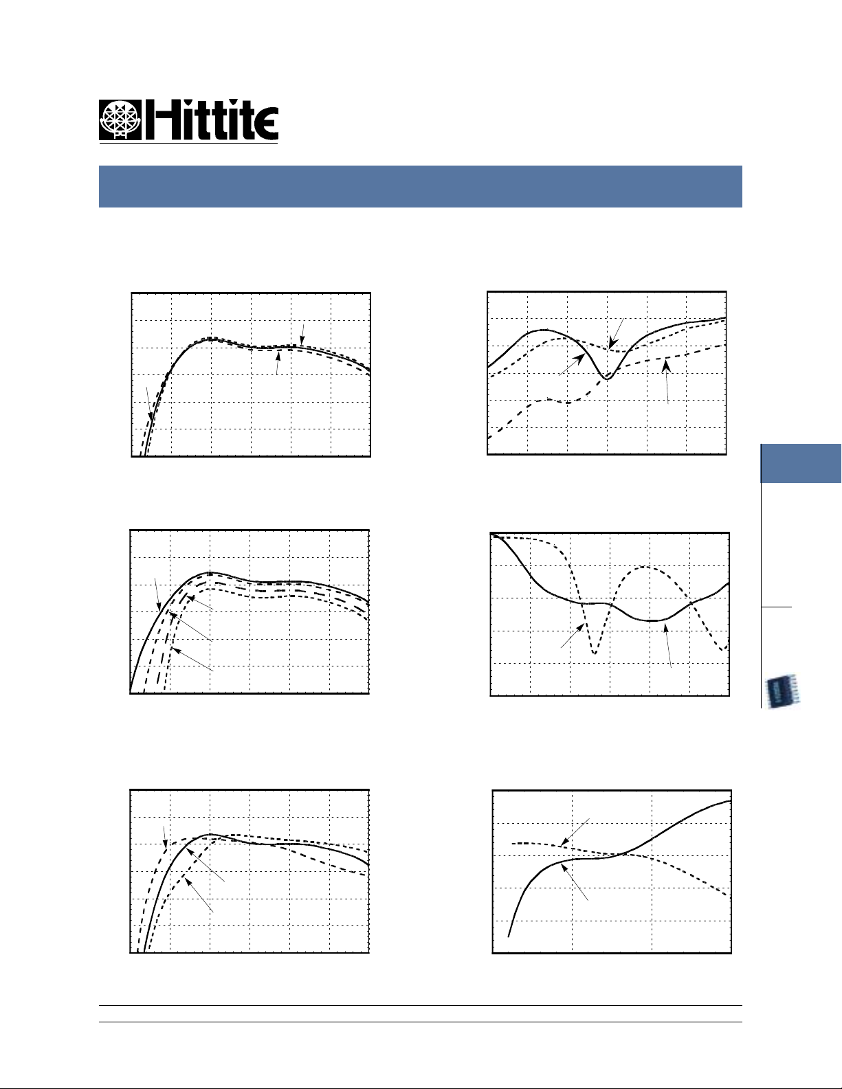
Conversion Gain vs.
Temperature @ LO = +10 dBm
0
-5
-10
-15
+25 C
-20
CONVERSION GAIN (dB)
-25
-30
1 1.5 2 2.5 3 3.5 4
FREQUENCY (GHz)
-40 C
+85 C
IF = 400 MHz
Conversion Gain vs. LO Drive
0
-5
+13 dBm
-10
-15
-20
CONVERSION GAIN (dB)
-25
-30
1 1.5 2 2.5 3 3.5 4
+7 dBm
+10 dBm
+5 dBm
FREQUENCY (GHz)
IF = 400 MHz
FEBRUARY 2001
Isolation @ LO = +10 dBm
0
-10
-20
-30
-40
ISOLATION (dB)
-50
-60
1 1.5 2 2.5 3 3.5 4
LO/IF
FREQUENCY (GHz)
RF/IF
LO/RF
IF = 400 MHz
Return Loss @ LO = +10 dBm
0
-5
-10
-15
RETURN LOSS (dB)
-20
-25
1 1.5 2 2.5 3 3.5 4
RF
FREQUENCY (GHz)
IF = 400 MHz
LO
4
MIXERS
SMT
IF Bandwidth @ LO = +10 dBm,
Conversion Gain vs. IF Frequency
0
IF = 800 MHz
-5
-10
-15
-20
CONVERSION GAIN (dB)
-25
-30
1 1.5 2 2.5 3 3.5 4
12 Elizabeth Drive, Chelmsford, MA 01824 Phone: 978-250-3343 Fax: 978-250-3373 Web Site: www.hittite.com
IF = 400 MHz
IF = 100 MHz
FREQUENCY (GHz)
Conversion Gain & Return Loss
0
IF Conv. Gain
-5
-10
-15
-20
-25
CONVERSION GAIN & RETURN LOSS (dB)
0 0.5 1 1.5
IF Return Loss
FREQUENCY (GHz)
4 - 165
Page 3
MICROWAVE CORPORATION
HMC285 SMT SINGLE-BALANCED MIXER 1.7 - 3.5 GHz
HMC285
4
MIXERS
SMT
FEBRUARY 2001
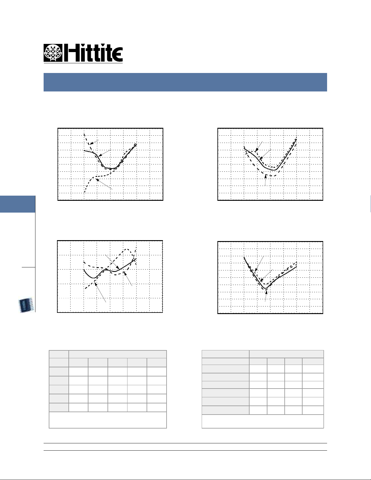
Input IP3 vs. LO Drive
25
24
23
22
21
20
19
18
INPUT IP3 (dBm)
17
16
15
1 1.25 1.5 1.75 2 2.25 2.5 2.75 3
+13 dBm
+10 dBm
+7 dBm
FREQUENCY (GHz)
Input IP2 vs. LO Drive
70
60
50
40
INPUT IP2 (dBm)
30
20
1 1.25 1.5 1.75 2 2.25 2.5 2.75 3
+10 dBm
+13 dBm
+7 dBm
FREQUENCY (GHz)
Input IP3 vs. Temperature
@ LO = +10 dBm
25
24
23
22
21
20
19
18
INPUT IP3 (dBm)
17
16
15
1 1.25 1.5 1.75 2 2.25 2.5 2.75 3
-40 C
+25 C
+85 C
FREQUENCY (GHz)
P1dB vs. Temperature
@ LO = +10 dBm
15
14
13
12
11
10
9
8
INPUT P1dB (dBm)
7
6
5
1 1.3 1.5 1.8 2 2.2 2.5 2.7 3
-40 C
+25 C
+85 C
FREQUENCY (GHz)
V00.0700
MXN Spurious Outputs
nLO
mRF 0 1 2 3 4
0xx-12.41133
1 10 0 38 23 43
25960614362
3 >110 87 90 80 88
4 >110 > 110 >110 >110 >110
RF= 2.6 GHz @ -10dBm
LO= 2.2 GHz @ +10 dBm
All values in dBc relative to the IF
Harmonics of LO
nLO Spur at RF Port
LO Frequency (GHz)
1.5 42 17 47 47
1.7 39164144
1.9 39 15 37 44
2.1 47 16 35 45
2.3 36 18 32 48
2.5 30 21 32 50
LO= +10 dBm
Values in dBc below input LO level measured at the RF port
1 2 3 4
12 Elizabeth Drive, Chelmsford, MA 01824 Phone: 978-250-3343 Fax: 978-250-3373 Web Site: www.hittite.com
4 - 166
Page 4
MICROWAVE CORPORATION
HMC285 SMT SINGLE-BALANCED MIXER 1.7 - 3.5 GHz
HMC285
V00.0700
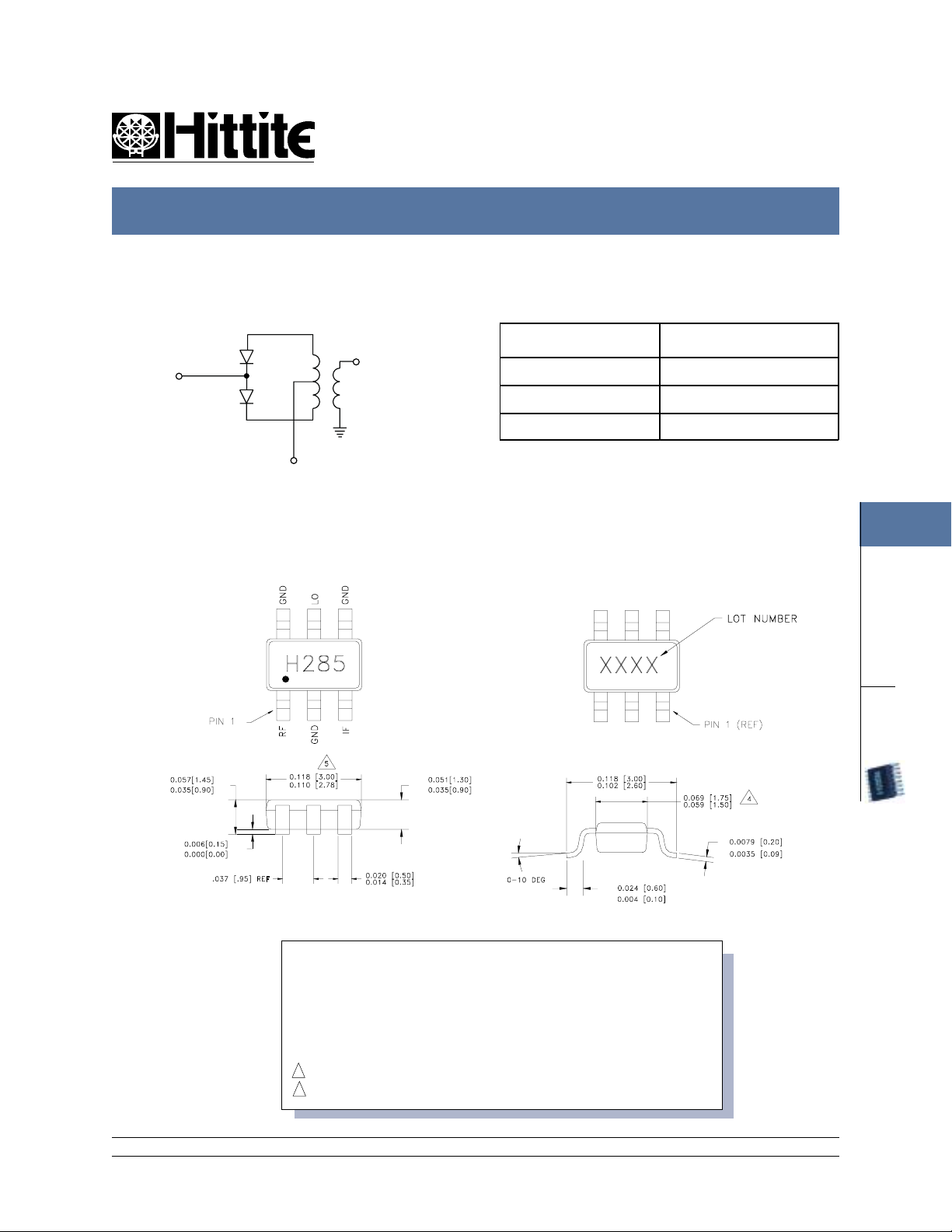
Schematic
LO
(PIN 5)
Outline Drawing
IF (PIN 3)
RF
(PIN 1)
GND
(PINS 2, 4, 6)
FEBRUARY 2001
Absolute Maximum Ratings
RF/ IF Inpu t +13 dBm
LO Drive +27 dBm
Storage Temperature -65 to +150 deg C
Operating Temperature -55 to +85 deg C
4
MIXERS
1. MATERIAL:
A) PACKAGE BODY - LOW STRESS INJECTION-MOLDED PLASTIC,
SILICA & SILICONE IMPREGNATED.
B) LEADFRAME MATERIAL: COPPER ALLOY
2 . PLATING: LEAD-TIN SOLDER PLATE
3 . DIMENSIONS ARE IN INCHES (MILLIMETERS),
UNLESS OTHERWISE SPECIFIED TOL. ARE ±0.005 (±0.13)
4. DIMENSION DOES NOT INCLUDE MOLDFLASH OF 0.006 (0.15mm) PER SIDE
5. DIMENSION DOES NOT INCLUDE MOLDFLASH OF 0.010 (0.25mm) PER SIDE
12 Elizabeth Drive, Chelmsford, MA 01824 Phone: 978-250-3343 Fax: 978-250-3373 Web Site: www.hittite.com
4 - 167
SMT
Page 5
MICROWAVE CORPORATION
HMC285 SMT SINGLE-BALANCED MIXER 1.7 - 3.5 GHz
HMC285
4
MIXERS
FEBRUARY 2001
The circuit board used in the final application should use RF circuit design techniques. Signal lines should have
50 ohm impedance while the package ground leads should be connected directly to the ground plane. A sufficient
number of VIA holes should be used to connect the top and bottom ground planes. The evaluation circuit board
is available from Hittite upon request.
V00.0700
Evaluation Circuit Board Layout Design Details
Layout Technique Grounded Co-Planar Waveguide (GCPW)
Material Rogers 4350
Dielectric Thickness 0.020" (0.51 mm)
50 Ohm Line Width 0.031" (0.79 mm)
Gap to Ground Edge 0.010" (0.25 mm)
Ground VIA Hole Diameter 0.014" (0.36 mm)
Connectors SMA-F ( EF - Johnson P/N 142-0701-806)
SMT
12 Elizabeth Drive, Chelmsford, MA 01824 Phone: 978-250-3343 Fax: 978-250-3373 Web Site: www.hittite.com
4 - 168
Page 6
MICROWAVE CORPORATION
HMC285 SMT SINGLE-BALANCED MIXER 1.7 - 3.5 GHz
HMC285
V00.0700
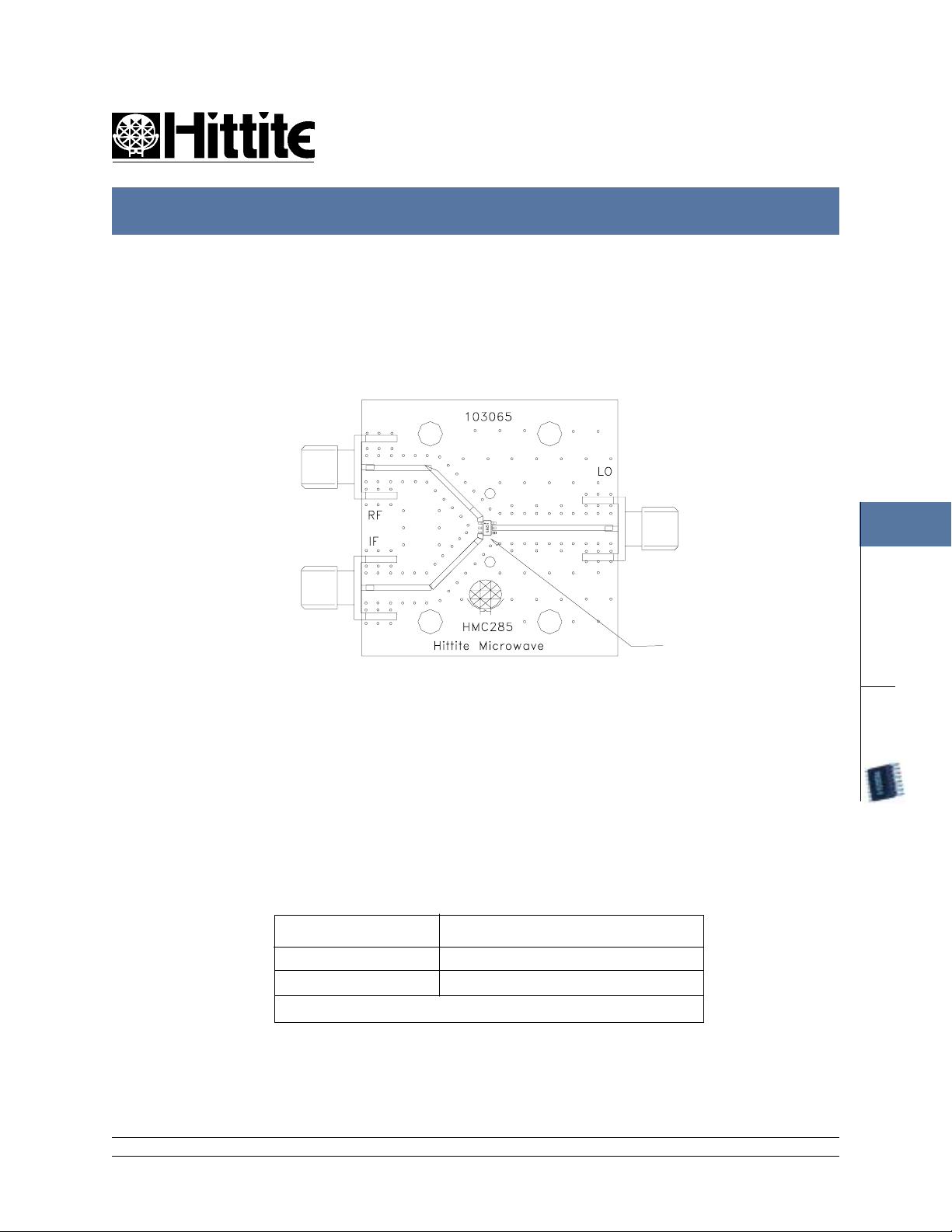
Eval Board Layout
J1
J2
U1
J3
FEBRUARY 2001
4
MIXERS
The circuit board used in the final application should be generated with proper RF circuit design techniques.
Signal lines at RF IN and RF OUT should have 50 ohm impedance and the package ground leads and exposed
ground paddle should be connected directly to the ground plane similar to that shown above. The evaluation
circuit board shown above is available from Hittite Microwave Corporation upon request.
List of Material
J1, J2, J3 PC Mount SMA Connector
U1 HMC285 Mixer
PCB 103065 Eval Board
* Circuite Board Material: 4350
12 Elizabeth Drive, Chelmsford, MA 01824 Phone: 978-250-3343 Fax: 978-250-3373 Web Site: www.hittite.com
4 - 169
SMT
 Loading...