

HIT HA17301P Datasheet
HA17301P
Quad Operational Amplifier
Description
The HA17301P is an internal-compensation quad operational amplifier that operates on a single-voltage
power supply. Typical applications for the HA17301P include waveform generators, voltage regulators,
logic circuits, and voltage-controlled oscillators.
Features
• Wide operating temperature range
• Single-voltage power supply operation
• Internal phase compensation
• Low input bias current
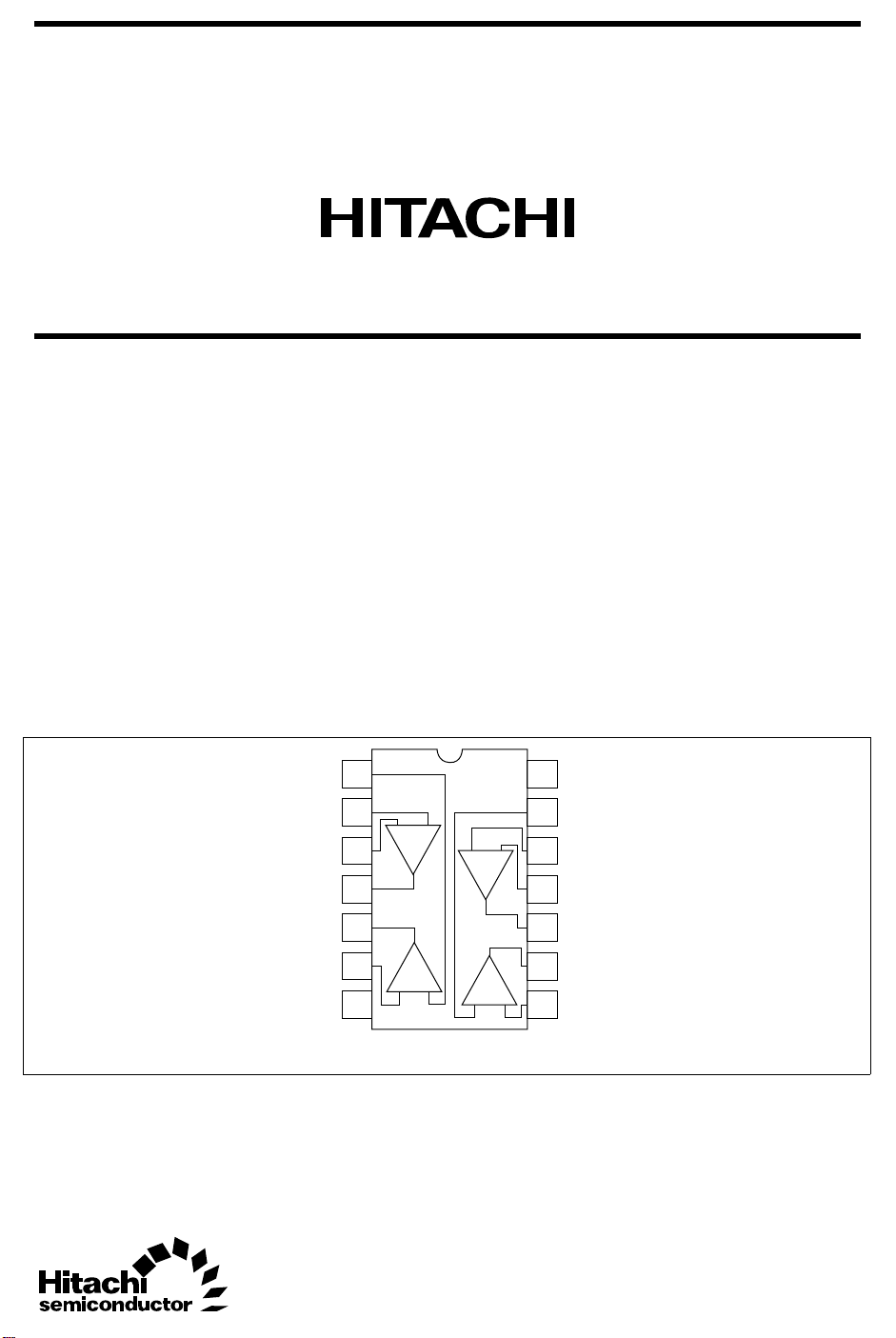
Pin Arrangement
Vin(+)2
Vin(+)1
Vin(−)1
Vout1
Vout2
Vin(−)2
GND
1
2
− +
3
1
4
5
2
6
−
7
+
+
+
(Top view)
14
V
CC
13
Vin(+)3
12
11
10
9
8
Vin(+)4
Vin(−)4
Vout4
Vout3
Vin(−)3
−
4
3
−

HA17301P
Circuit Structure (1/4)
Vin(−)
Vin(+)
V
CC
Vout
GND
2

HA17301P
Absolute Maximum Ratings (Ta = 25°C)
Item Symbol Ratings Unit
Power-supply voltage V
CC
Noninverting input current Ir 5 mA
Sink current Io sink 50 mA
Source current Io source 50 mA
Allowable power dissipation* P
T
Operating temperature Topr –20 to +75 °C
Storage temperature Tstg –55 to +125 °C
Note: This is the allowable value up to Ta = 50°C for the HA17301P. Derate by 8.3 mW/°C above that
temperature.
Electrical Characteristics (VCC = +15 V, RL = 5.0 kΩ, Ta = 25°C)
Item Symbol Min Typ Max Unit Test Conditions
Voltage gain A
Supply current I
Input bias current I
Current mirror gain A
VD
CO
I
CG
IB
I
Output source current Io source 3 13 — mA VOH = 0.4 V
Output sink current Io sink 0.5 0.75 — mA VOL = 0.4 V
Output voltage V
V
V
OH
OL(inv)
OL(non)
Input resistance Rin 0.1 1.0 — MΩ Inverting input only
Slew rate SR — 0.2 — V/µsCL = 100 pF, RL = 5.0 kΩ
Bandwidth BW — 2.6 — MHz AVD = 1
Phase margin φm — 87 — deg
Power-supply rejection
PSRR — 63 — dB f = 100 Hz
ratio
Channel separation CS — 63 — dB f = 1.0 kHz
1,000 1,400 — V/V
— 7.7 10 mA Non inverting input open
— 8.3 14 mA Non inverting input grounded
— 80 300 nA RL = ∞
0.80 0.94 1.16 A/A Ir = 200 µA
— 10 — mA VOH = 9.0 V
13.5 13.9 — V
— 0.04 0.1 V Inverting input driven
— 0.55 — V Non inverting input driven
28 V
625 mW
3
HA17301P
HA17301P Application Examples
The HA17301P is a quad operational amplifier, and consists of four operational amplifier circuits and one
bias current circuit. The HA17301P features a wide operating temperature range, single-voltage power
supply operation, internal phase compensation, a wide zero-cross bandwidth, a low input bias current, and a
high open-loop gain. Thus the HA17301P can be used in a wide range of applications. This section
describes several applications using the HA17301P.
HA17301 Circuit Operation
V
CC
Q
C
3 pF
Inverting input
3
Non inverting
input
2
D
1
GND
Bias circuit
5
1
Q
Q
3
Q
4
1
Q
10
Op amp 1
Q
2
4
Output
Figure 1 HA17301 Internal Equivalent Circuit
Figure 1 shows the internal equivalent circuit for the HA17301P bias circuit and one operational amplifier
circuit (Op amp 1).
Op amp 1 is basically an emitter ground type operational amplifier in which the input transistor Q1, the
buffer transistor Q4, the current source transistor Q5, the output emitter-follower transistor Q2, and the
current source transistor Q10 form an inverting amplifier. The voltage gain of this circuit is all given by the
transistor Q1, and the adoption of the current-supply load Q5 allows this circuit to provide a large open-loop
gain even at low power-supply voltages. Next, the emitter-follower transistor Q2 lowers the output
impedance of this circuit. The use of the power-supply transistor Q10 as the load for Q2 gives this circuit an
extremely large dynamic range, and essentially an amplitude from ground to (VCC – 1) can be acquired.
Also, the buffer transistor Q4 is used to reduce the input current without increasing the DC input voltage
level. Since the capacitor C1 is used to preserve stability when this inverting amplifier is used as a closed
circuit, no external compensation is required.
Now consider the non inverting circuit. Assuming that the current amplification ratio provided by Q3 is
adequately large for the current flowing into the non inverting input, then all that current will flow through
diode D1 and the voltage drop induced in the diode D1 by this input current will be applied to the Q3 baseemitter junction. Therefore, if D1 and Q3 are matched, a current equal to the input current will flow in the
Q3 emitter. Assuming that the current amplification ratio provided by Q3 is adequately large, a current equal
to the input current will flow in the Q3 collector. This is called a “current mirror”, and when an external
feedback resistor is used, a current equal to the non inverting input current will flow in this resistor and thus
determine the output voltage.
4
HA17301P
Inverting Amplifier
There are three bias techniques for biasing the inverting amplifier, the single power supply bias technique,
the NVBE bias technique, and the load voltage bias technique.
1. Single Power Supply Bias Technique
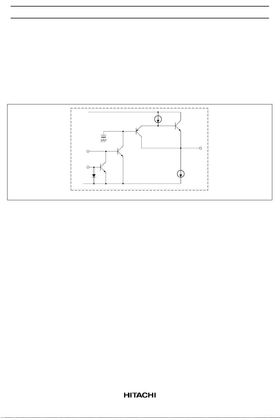
Figure 2 shows a common AC amplifier that is biased by the same power supply as the supply that
operates the amplifier.
R
2
= −
R
R
Vout
Vin
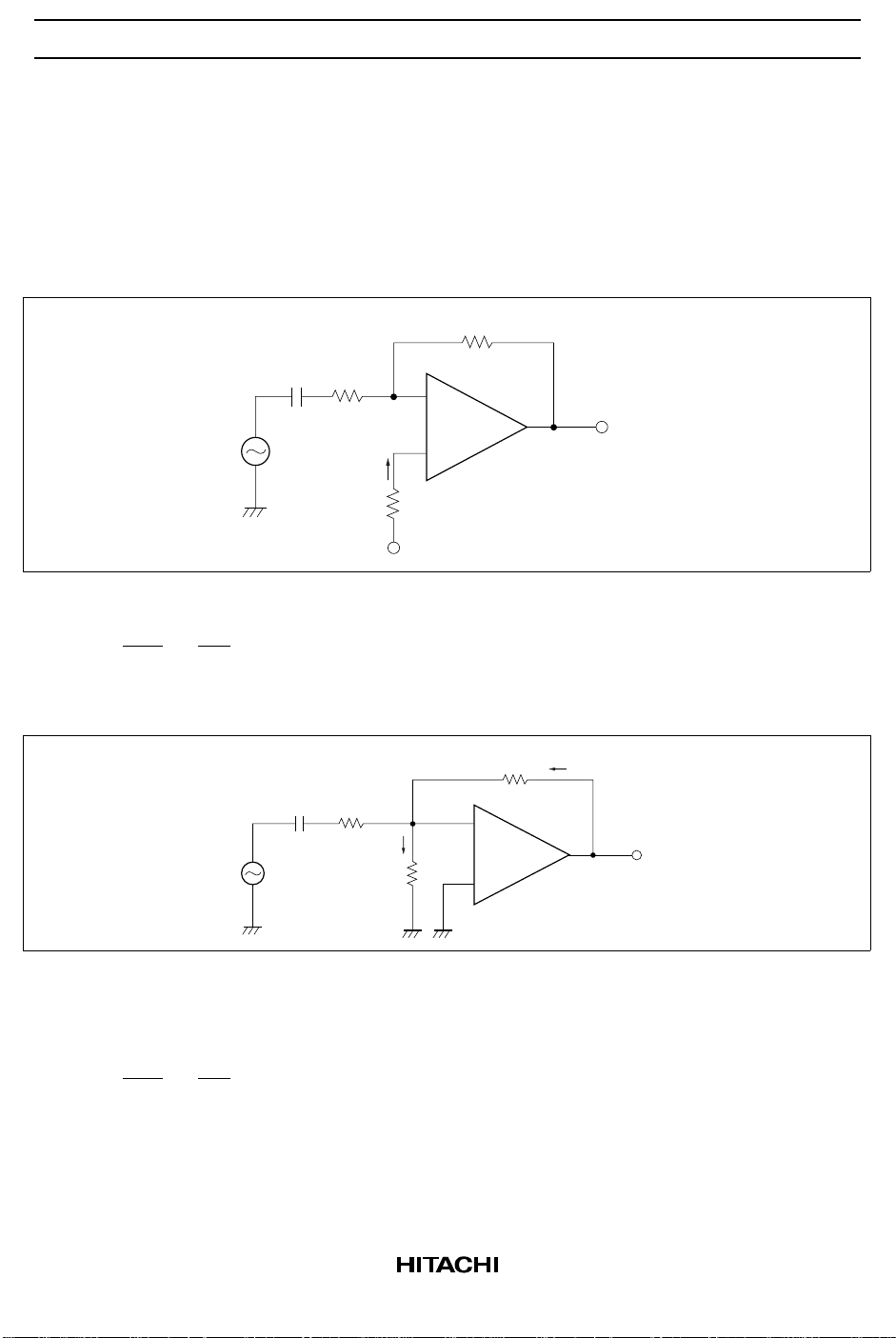
2. NVBE Bias Technique
−
D
+
1 MΩ
+
V
500 k
−
+
Cin
0.1 µF
Vin
R
1
50 kΩ
R3 = 2R
V
V
D
+
I
2
Figure 2 Single Power Supply Bias Technique
2
1
Vin
Cin
0.1 µF
R
1
100 kΩ
V
RE
I
82 kΩ
R
3
−
+
(1)
R
2
1 MΩ
Vout
−
I
Vout
Figure 3 NVBE Bias Technique
This is the most useful application of an inverting AC amplifier. In this circuit, the input bias voltage
VBE for the inverting input is determined by the current that flows to ground through the resistor R3.
= −
R
2
R
1
(2)
Vout
Vin
5
 Loading...