

Page 1
T
I
---
-
-l
e
Page 2

Contenls
precautions
Salety
Technical
data .........
Levelling........
Setling
Aligning
Measuring
Marking
using
the
Frame clamp
Magnetic bracket
Wall
Pointlocator....
Checking
accuracy
Horizontal
Vertical
Maintenance
Warranty....
FCC stalement
EC declarati0n
26
out right angles
plumbing
and
oul inclinalions
out.
accessories .......
...
bracket ....
laser
beam
beam
(applicable
ol c0nt0rmity.
.......
........
....
in U.S.)
....
precaulions
Salely
27
31
37
38
39
40
41
41
41
42
42
43
43
45
46
47
48
49
A. The 0peraling inslructions and safety
observed. only
B. Laser
The PlVl 10laser level
based 0n
reflex
laser beam. This
measu res.
Nevertheless,
into the liqht source.
Laser warnings tor
then can the t00l be operated salely.
is
a laser sa{ety class
the lECB25-1/EN60825 standards
protects
the
eyes should
tool
may be operated
with the sun, care sh0uld
as
tlSA based
21
on
ICEnEETil'L
,
:l\kl
DO N()l
l\l()itl \\l
ilh
21 CFR 1 040
I ASFIt RA{)1,\1ION
J
(
l
ASS
This Laser Pr0duct
as aDol cable.
II LASLR l'ltot)lJC
c0mplies vi
precaulions
2 tools which complies with requirements
the operator or any
(Class
with0ul the need
I
I
laser warnings based
Mffi
CFR
read in full and striclly
musl be
ll
bystander happen look briefly
be taken t0
based 0n
for
21
1040). The blink
CFB
any addilional
lo0king directly
av0id
0n lEC825/EN60825
into the
protective
Page 3
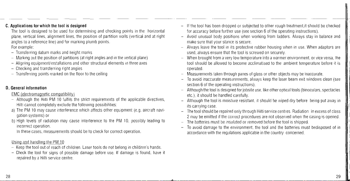
C. Applications
The tool
plane,
angles
For example:
Transferring datum marks and height marks
-
Marking outthe
Aligning
-
Checking and
-
Transferring
D.
General
EMC
lor which
is
designed to be used f0r delermining and
vertical lines,
to a reference linel and
equipment/rnstallati0ns and
poinls
inlormalion
(electromagnetic
Although the
Hilti
cann0t c0mpletely exclude the
The PIV 10 may cause interference which
a)
gation
systems) of
levels
Hjgh
b)
0f
t0ol is
the
alignment
for
position
partiti0ns (at
of
transferring right angles
0n
marked
comoatibil!y)
Hrlti
Pl\4 10
Jullils
radjatjon may
incorrect operation.
ln these cases. measurements
and
Using
Keep
-
Check the tool for
-
repaired
28
the
handling
t00l 0ut 0f
Hilli
by a
the
PM 10
01 chrldren. Laser to0ls d0 n0t
reach
possible
signs of
service centre.
designed
p0siti0n
lines. the
marking
fl00r t0
the
0ther
0f
plumb points.
right
angles
structural
the ceiling
the stricl requirements of
possibilities.
f0llowing
affects
interference
cause
to
be
sh0uld
check
damage before
p0ints
checking
partiti0n
and in the venical
elements
walls
In three
in the horizontal
(vertical
and at
plane)
axes
the applicable directives,
PlVl
(e.9.
possibly
10.
operati0n.
in
children's
aircfaft navi-
leading
hands.
other equipment
to the
lor
correct
bel0ng
use. lf damage is lound. have rt
right
lf the
has
tool
for
accuracy
Avoid
make
Always leave
used, always ensure
When
tool
perated.
o
Measurements taken through
To
avoid inaccurate
section 6 of
Although the tool is designed I0r
been dropped or sublected to other r0ugh
belore Jurther
unusual body
thai
sure
the
brought
should be
y0ur
from a very l0w lemperature into a warmer environment. 0r vice versa,
allowed
use
positions
stance rs secure.
its
tool in
that the
to
become acclimatised
protective
tool
measuremenls,
the
operating
Instructi0ns).
(see
section 6 ol the
vrorking from
when
rubber housing when
is
screwed on
panes
glass
ol
allvays keep
j0bsite
use,
or other
like other
lreatment,it
operating
ladders.
securely.
to
the ambient temperature before
objects
the
laser beam exit
opiical
sh0uld be checked
instructi0ns).
Allvays
in
may
in
stay
use. When adaptors are
inaccurate.
be
windows
(bin0culars.
tools
balance
clean
spectacles
and
the
it
(see
is
etc.), it should be handled carefully.
Although the to0l is m0isture
rts
carryrng
case.
resistanl.
it should
be rviped dry
belore
being
put
av/ay in
ThetoolshouldberepairedonlythroughHiltiservicecentres.Radiati0n inexcessofclass
2
to
may be emitted
Tbe balteries must be
T0
avOid damaqe
accordance with the regulations applicable in the c0un1ry concerned.
if the c0rrect
to the envir0nment.
procedures
rnsulaled
or removed before the tool
the
nOt
are
tool and
0bserved
llatleries
the
when the casing is
is
shipped.
bedisposed 0f
must
opened.
in
Page 4
@..
?
@@
aol
\9'
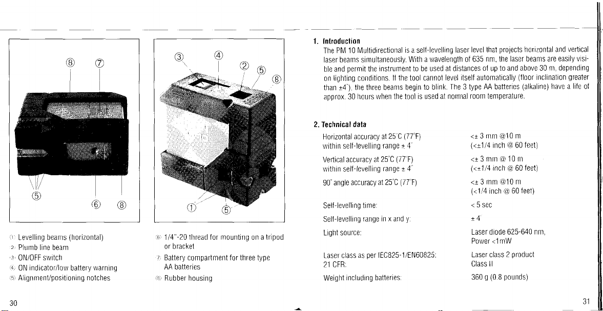
1. lnlroduclion
PM 10 Multrdirectional
The
laser beams simultaneously.
permit
ble and
lighting c0nditi0ns.
on
than t4"),
approx.
the
the three beants begin
hours when the t0ol is used
30
level thal
is a seltlevelling
a wavelength 0f
With
laser
635
instrument t0 be used at distances
the
11
tool cannol
level itself aulomatically
The 3 type
to blink.
at n0rmal
r00m temperature.
proiects
nm,
laser beams are easily
the
01
10 and above 30
up
AA
batteries
h0rizontal and
(floor
inclination
(alkaline)
vertrcal
visi-
m, depending
greater
life
have a
ol
ir'
2,
i5l
30
beams
Levelling
P[rmb
line beam
switch
0N/0FF
indicator/low
0N
Alignment/positioning
(o
(horizontal)
warning
battery
notches
@
i6
1
/4"-20
llrackel
or
z
Battery
AA batteries
:8.
Rubller
lhread f0r
mounting
0n a
compartment for three type
housing
trip0d
2.
Technical
Horizontal
data
accuracy a1
within self-levelling
Vefiical accuracy al25'C
vrithin sel{-levelling
accuracy
90'angle
SelI-levelling
Sell-levellinq
tinre:
range
Light source:
Laser class as
per
2] CFR:
including batteries.
Weight
(77'F)
25 C
range 14'
(17"F)
ranqe
4
I
(/7'F)
aI25"C
y.
in x and
lECB25- 1 /EN60825
<t
3Inm
(<t114
<t 3 mm
(<t114
<r3mm@10m
(<1/4
@10
inch @ 60
10 m
@
inch @ 60
(@
inch
60
m
feet)
<5sec
!4
Laser diode 625-640
<1mW
Poiryer
product
Laser class
Class
2
ll
360g(08pounds)
feet)
feet)
nm,
Page 5

D
imensions.
Distance from
centre of laser
Batte ries:
edge of housing
beam:
ltems supplied
50 mm x 108 mm x 95
nrm
(2"x43"x3.75")
to
(1")
25
mm
AA alkaline or
AA
Ni/Cd
(3
balreries)
3.
Inslrumenl
only
Battery lile
with 3
vrith
3
AA
Ni/Cd
Automatic cut-out:
0perating temperature:
Storage temperature.
Insulation
class:
32
alkaline
batreries.
llatteries
Approx
30
Approx. 7 h
After
approx. 20 minutes
-20'C
to 45'C
-40
to
C
63
lP54
including
not
pa
rtme nt
conr
h
(-4"F
to 1 1 3'F)
(-40
C
F io 145
F)
battery
I
2
3.
5
Sailcloth
Ptvl10
plate
Target
0perating
locator
Point
case
instructions
Page 6

Set
4. Working
with the PM10
The insulating sticker
for the lirst
operated
must be
time.
removed
{r0m the battery
c0mpartmenl
belOre
the tool is
W'W'ffiffi'
.M
rll
Sailcloth case
t..2)
PN/1 O
plate
Target
3)
a4)
0perating
,5
N,4agnetic bracket
34
instructions
.q..
Wall
7t
Frame
8,1
Carrying case
!l
Point localor
bracket
clamp
,
qw,
A.
the t00l 0n a stable
up
Set
the Iloor
a) 0n
a tripod
b) 0n
the magnetic bracket
c) 0n
the lrame clamp
d) 0n
Activate the 0N/0FF
itsell 0n
stabilises
lf the laser sp0t
(begins
tally
B. Deviation
the distance
whereby
to the distance
markings on
The
surface or supp0rt.
and then
switch
the target
0n the
to blink
from the horizontal/vertical
lrom the edge 0{
the housing are used
(<
5s).
target begins
when 0utside
from the edge 0f
the target
the sell-levelling
wait until
to
blink.
line can
the tool
plate
positi0n
to
the laser sp0t
tool must be
the
range ol
then be read
t0 the centre ol
t0 its centre
the tool.
rep0siti0ned
h0rizon-
I 4").
target
Jr0m the
the beam c0rresponds
(25
mm or 1
")
plate,
Page 7

Leve | |
ing
Setling out
right angles
wffi
Hffiffi
u
1)
ll
-.ll
.l(ffiw
l,)A*
..
Z,Z,Z
z-,r=-_t
t*r&
i
a'
.4
'+-.
\-\
Page 8

Aligning and
plumbing
Measuring
slope
oul
ratio=
inclinations
*_ ?o.q
gg
,
=
't
h=1.5cm
I
..t:,...
-
-__d
2oo cm
-
ffi
percent
O
=
-Jt=1
5#q
=0.75o/o
I
38
Page 9

4.1 Usino the accessories
Frame clamp
a)
When using
slid
tive
''''
i
a:'
|
?
-
o:
NI
:-
t_
1"
'
,..
(25,4mm)
the Frame clamp
the
stationary
0nto
cover should
be frtted over lhe
tif-
E'-+
(e.9.
0f the clamp by
law
f rame), the magnetic bracket can
at a door
way
the rail
magnet.
0f
+---
the rear. The
at
be
protec-
v,
b) Magnetic
protective
The
bracket.
brackel
cover should
frOm the magnets
rem0ved
#.
using the
be{ore
S
&
, i't
i'^\
magnetic
Page 10

c)
Wall
bracket
The wall brackel
Screvrs or
PlVl
10 can be set Lrp
rem0ve0).
cOver
nails
can be used to
is
used
on
for mounting
jasten
the
the wall bracket
PIVI 10
the
wall bracket t0 sLrrfaces
with
non-nragnetic
on a
the magnetic
this kind. The
0f
holder
surface.
(protective
Checking
The PM
tool
accuracy
10 is adjusted
si0n tools, its
has
been subiected
accuracy
precisely
must
be checked
to heavy
it leaves
be{ore
at regular intervals. This applies, in
vibration 0r
our
an impact.
premises.
5.1 Horizontal laser beam
1
2.
Place the
and direct
laser spot
the 0pposite
PM 1 0 on
the laser
.r'r,vith
a
wall. lVark
the fl0or at
beam
cross.
the end
towards the
Pivot the
the centre of
0f a long
closest
tool
thr0ugh 1 80' and direct the beam
the
laser spot
Placelhet00lontheflooratwall(B)anddirectthebeamtowardswall(B).Mark
the
direct the beam
wrln a cross.
centre
of
the laser
towards
3l
wilh
a
spot
the 0pp0site wall.
cross. Pivot
Mark the centre
room
wall
(1
(A).
12.
$/ith
the t00l
0-20 m
lMark
with all
as
particular,
or 60-1
the centre o{
a cross.
through
the laser spol
of
preci-
ifthe
00 leet)
the
towards
180' and
4
:
(=d2).
the
'/,
point
this figure,
the
distance between
then
mark the
d1 and
points rr
points
d1 and'1.
lies
below and
d1
and
must
nOt exceed 3mm.@
please
and
lie above
should be calculated.
d2
'/,
3. N0w measure
0)
Poinl locator
point
The
nrark from the fl00r
a
pornt
the
on the lloor
:.
key
5y
locator
locator rs
':..
The PM
way
of
can be
10 the ceiling.
positioned
groove
the
when transferring
used
0n the desrred nrark
then ile
1 0 can
0n its underside.
The
hole in
slid 0nt0 the
cQ)
r
t
42
nnl
ween the centre ol
4.
Compare
When both
-
ween
lf one
the values'/,
The deviation
exceed
p0int
mid
the centre of
3
:zr (0r
(or
bel0w) the exact
the other
must be
d2
y0ur
c0ntact
p0ints'1.
between
and
added
10m
.+;
(-d1
2nfl
and d2. The imaginary line bet-
d1
horizontal, the
lies above
together.
@ 60leet). lfthe
Hilti service
h0riz0ntal
the
lies exactly
d2
a
with the exact horizontal
)
point
(1/4"
local
and between
)
(T).
difference
exact
centre.
h0rizontal
deviation
points
(T).
:
bet-
(T),
does
43
Page 11

5.2
Vertical
beam
(laser
plumb
line)
1. I\4ake a mark
r00m.
(a
cross) 0n the
floor
oI a
high
Lr*.*.J
L'",#
@1.,''
44
<2x3mm@10m
t/z
T
D
d2
w
;l
90'
90'
2. Place the PM 1 0 0n
3. Pivot the tool through 90
4. Repeat the instructions at
the laser
where
directed
the cr0ss on the Jloor and again
0n
mark to the ceiling.
two more times.
Four marks have now been made on
5.
Measured across
between
mm/10 m
exceeded,
centre.
the
cross and
strikes the ceiling.
beam
the
diagonal,
contact
(lhe
paragraph
your
towards the ceiling). Set it up exactly
these marks must not exceed
(2
x 114"160 feet).
please
pOint
mark the
laser beam still
transler this
3
the
ceiling.
the distance
2 x
lf this figure is
Hilti service
3
Page 12

Ma i ntenance
Keep
the three laser beam
gently
wind0w
We recommend
period.
long
it
and dry
wilh a cl0th. D0 not use
that the
batteries are
windows clean.
exil
Use a soft cloth and a little soap. Wipe
removed
if the tool
chemical
cleaning
is not re0uired
agents.
to be used for a
the
Warranty
7.
Hilli v/arranls that the
warranty is valid as
properly
iced
are made within l2
system is maintarned.
spares may
placenrent
normal
Additional
In
damages, losses
ily t0
a
For repair
01 delective
wear and
claims
particular,
use the
parlicular purpose
or
tool
supplied
long as
the
in accordance with the
and
months
{rom the date
This means that only original Hilti consumables, c0mponents
be
used in
t001. This warranly
the
pais
lear are not
are excluded, unless slringenl nali0nal
is n0t
Hilti
t00l l0r any
replacement.
0bligated
0r expenses in
purp0se.
are specilically
send
the defect to the address 0fthe
Thrs constitutes
c0fltemporane0us comments and oral or
0r
Hilti's entrre
Iree
is
of detects
tool is 0perated
Hilti
Parts requiring repair or replacement as a
only.
by thjs
covered
l0r direcl,
connection
lmplied
in material and workman-ship.
handled correctly, cleaned and serv-
and
0perating
0f
warranty.
wilh,
warranlies
Instructi0ns,
(invoice
the sale
provides
indirecl,
date),
the free-01-charge repair 0r
prohibit
rules
incidenlal
0r by reason 01, the use of, or
merchantability
0l
excluded.
t00l
lOcal
obligation
and/or
Hiltr
with regard to warranty and
parts
related
marketing
organization
\,vritten
agreements c0ncerning
immediately upon discovery
all
and
or
provided.
supersedes
This
warranty claims
the technical
and
result
exclusi0n.
such
c0nsequenlial
inabil-
fitness f0r
0r
pri0r
all
warranties.
re-
0f
0f
46
47
Page 13

FCC
B.
slalemenl
This equipmenl has been tested and Iound to comply with the limlls lor a class B drgital
device. 0ursuant
These limits are designed t0
in a residential installation. This equipmenl
energy and,
ful inler{erence to radio communications. Hovrever. lhere is n0
ference will not occur
rnterlerence 10 radi0
equipment off and on, the user is encouraged t0 try 10 c0rrect the interference by one or
more of the lollowing measures.
Reorient
-
Increase lhe separalion between lhe equipmenl and receiver.
Connect the e0ui0ment
-
ceiver
Consult the dealer or an experienced radio/TV technician for help.
Changes 0r modilications
aulh0rity
4B
(applicable
if not installed
rel0cate the receiving
0r
is
connected.
t0
operale
in
U.S.)
t0
15
the FCC rules.
Dart
of
provide
reasonable
in
and used
particu
in
a
television reception. which
0r
into
not
expressly approved by Hilti lor compliance couid void the user's
the
equipmenl.
accordance
ar installat on.
antenna.
an 0utlet on a circuit diflerent ir0m that
protecli0n
generates,
uses and can radiate radio frequency
with the instructions, may
lf this
equ
can
against harmful interference
pment
lle
determined by
cause
gLrarantee
does cause harmful
that inter'
turning the
to
which the re-
harm-
conlormity
sation
1 accordjng
tioning Systems
Pos
Business
997
ol
Plvl10
92500'999999
1997
0ur s0
0n
documents:
Unit
EC declaration
Designationr
Serialno.:
Year of design:
we declare.
standard
EN 5501
Hilti Corporation
/r,*/^7
Armin Spiegel
Leiter
Head of
09/1
e responsibility.
provisi0ns
to the
L
P0siti0ning
this
that
0f the directives
Systems
pr0duct
c0mplles
B9/336/EEC
/t t [-)
cN
Heinz
Dr.
Ent\'/ cklung
Devel0pment
09/1 997
with the
,/,-- l/
Kousek
Positioning
lvlanager
tollowinql
Systems
Positi0ning
standards
Systems
0l
 Loading...