

Page 1
7 8
Hilti Corporation
LI-9494 Schaan
Tel.:+ 423/ 23421 11
Fax: +423 / 23429 65
www.hilti.com
PD 42
Operating instructions en
Brugsanvisning da
Bruksanvisning sv
Bruksanvisning no
Käyttöohje fi
Инструкция по зксплуатации ru
Lietoßanas pamåcîba lv
Instrukcija lt
Kasutusjuhend et
Hilti = registered trademark of Hilti Corp., Schaan W 3399 0307 00-Pos. 2 1 Printed in Liechtenstein © 2007
Right of technical and programme changes reserved S. E. & O.
320299 / B
*320299*
320299
Page 2

12
6
+Ç34+“+±+≠
+#
+[+{
+]
+|
5798
1
2
1
3
4
5
6
1
2
1
2
3
5 6
4
Page 3
PD 42 laser range meter
It is essential that the operating instructions
are read before the tool is operated for the
first time.
Always keep these operating instructions
together with the tool.
Ensure that the operating instructions are
with the tool when it is given to other
persons.
Contents Page
1. General information 25
2. Description 26
3. Insert tools, accessories 30
4. Technical data 30
5. Safety rules 31
6. Before use 33
7. Operation 37
8. Care and maintenance 44
9. Troubleshooting 45
10. Disposal 46
11. Manufacturer’s warranty ಣ tools 47
12. EC declaration of conformity 47
1. General information
1.1 Safety notices and their meaning
DANGER
Draws attention to imminent danger that could lead
to serious bodily injury or fatality.
1 These numbers refer to the corresponding illustrations. The illustrations can be found on the foldಣout
cover pages. Keep these pages open while studying
the operating instructions.
In these operating instructions, the designation “the
tool” always refers to the PD 42 laser range meter.
Parts, operating controls and indicators 1
On/off button
@
Side measure button
;
Graphic display
=
Measure button
%
Delete (clear) button
&
Horizontal bubble
(
FNCಣbutton
)
Folding spike
+
{/" thread for PDA 71 measuring extension
§
Rear contact points
/
Minus button
:
Plus button
·
{/" thread on the underside
$
Reference button
£
Optical sight
|
Laser exit lens
¡
Receiving lens
Q
Vertical bubble
W
1.2 Explanation of the pictograms and other
information
Warning signs
en
WARNING
Draws attention to a potentially dangerous situation
that could lead to serious personal injury or fatality.
CAUTION
Draws attention to a potentially dangerous situation
that could lead to slight personal injury or damage to
the equipment or other property.
NOTE
Draws attention to an instruction or other useful
information.
General
warning
25
Page 4
en
Symbols
Read the
operating
instructions
before use.
Return waste
material for
recycling.
Laser class II according
to CFR 21, § 1040 (FDA)
Location of identification data on the tool
The type designation and serial number can be found
on the type identification plate on the tool. Make a
note of this data in your operating instructions and
always refer to it when making an enquiry to your
Hilti representative or service department.
Type:
>1/4s
Laser class 2
in accordance
with
EN 60825ಣ
1:2003
Battery status
indicator
Do not look
into the beam.
Hardware
errors
Type identification plate
AVOID EXPOSURE
DIN EN 60825-1:2003
PD 42
Made in Germany
Hilti = trademark of Hilti Corp., Schaan, LI
Serial number
Laser radiation is emitted from this aperture
LASER RADIATION - DO NOT
STARE INTO BEAM
620-690nm/0.95mW max.
CLASS II LASER PRODUCT
This device complies with part 15 of
the FCC Rules. (1) This device may not
cause harmful interference, and (2) this
device must accept any interference received, including inter-
ference that may cause undesired operation.
Item No.: 30673 Power: 3V nom/400 mA
Manufactured:
PD 42
Temperature
indicator
Unfavorable
operating
conditions
01
Serial no.:
2. Description
2.1 Use of the product as directed
The tool is designed for measuring distances, adding and subtracting distances and offers many practical
functions such as a timer, area and volume measurement, min/max calculation, setting out, painter’s area
measurement, Pythagoras function and data memory.
Do not use the tool as a leveling tool.
Measurements taken from plastic foam materials such as polystyrene foam, from snow or from highly reflective
surfaces (mirrors, glass, etc.) may produce inaccurate results.
26
Page 5

The tool and its ancillary equipment may present hazards when used incorrectly by untrained personnel or
when used not as directed.
Take the influences of the surrounding area into account. Do not use the appliance where there is a risk of fire
or explosion.
Observe the information printed in the operating instructions concerning operation, care and maintenance.
To avoid the risk of injury, use only genuine Hilti accessories and additional equipment.
Modification of the tool is not permissible.
NOTE
Observe the permissible operating and storage temperatures.
2.2 Display
The measurements, settings and tool status are shown in the display. When the tool is in measuring mode,
the measurements taken are shown at the bottom of the display area (the result line). When using a function,
e.g. area measurement, the distances measured are shown in the intermediate result line and the calculated
result is shown at the bottom of the display (the result line).
2.3 Display illumination
In low light conditions, the display is illuminated automatically as soon as a button is pressed. The display
illumination intensity is reduced to 50% after 10 seconds. If no button is pressed over a period of 20 seconds,
the display illumination switches off automatically.
NOTE
Illumination of the display consumes battery power. Shorter battery life is therefore to be expected when this
feature is used frequently.
2.4 Basic principle
The distance is measured along a laser beam emitted by the tool to the point at which the beam strikes
a reflective surface. The target from which the measurement is taken is clearly identified by the red laser
measuring spot. The range of the tool depends on the reflectance and structure of the target surface from
which measurements are taken.
en
2.5 Measuring principle
The tool emits a visible laser beam carrying signal pulses which are reflected by the target. The time between
reflected pulses is used as a basis for determining the distance.
This measuring principle permits highly accurate and reliable measurement of distances to objects without
need for special reflectors.
2.6 Standard measuring display mode
Standard measuring display mode is always activated when the “On/off” or “Measure” button is pressed to
switch the tool on.
27
Page 6

2.7 Symbols in the display
Temperature Temperature too high
Unfavorable operating
conditions
(>+50°C) / too low (<ಣ
10°C).
Insufficient reflected
laser light.
en
General hardware error Switch the tool off and on again. If the fault persists,
2.8 Control panel
Measure button Activates the laser beam.
Plus button Initiates distance, area and volume addition.
Minus button Initiates distance, area and volume subtraction.
FNCಣbutton Always activates the previously used function.
Delete (clear) button
The Cತbutton has various
functions depending on
operating mode.
Allow the tool to cool down or warm up.
Observe the minimum measuring distance (50 mm
from the front edge of the tool); clean the lenses;
take measurements from a different surface or use a
target plate.
please contact Hilti Service.
Begins distance measurement.
Activates continuous measuring mode (long press,
approx. 2 sec.).
Stops continuous measuring mode.
Adds distances in standard measuring and painter’s
measuring modes.
Adds areas and volumes in the relevant modes.
Subtracts distances in standard measuring and
painter measuring modes.
Subtracts areas and volumes in the relevant modes.
Press the button repeatedly to activate or select the
functions one after the other (when no measurements
have been taken).
When measurements have been taken: Deletes all
measurements and restarts the function.
Stops continuous measuring (tracking).
Stops continuous measuring (tracking).
Clears the standard measurement display.
Clears the last measurement and returns to
“Functions”.
Clears data memory (long press when data memory
is displayed).
Ends the function if no measurements have been
taken.
28
Page 7
On/off button When the tool is switched off, press the button
briefly to switch it on.
When the tool is switched off, press and hold the
button to activate the menu.
When the tool is switched on, press the button
briefly to switch it off.
Reference button Switches between the various measuring reference
points (front, tripod thread on the underside, rear).
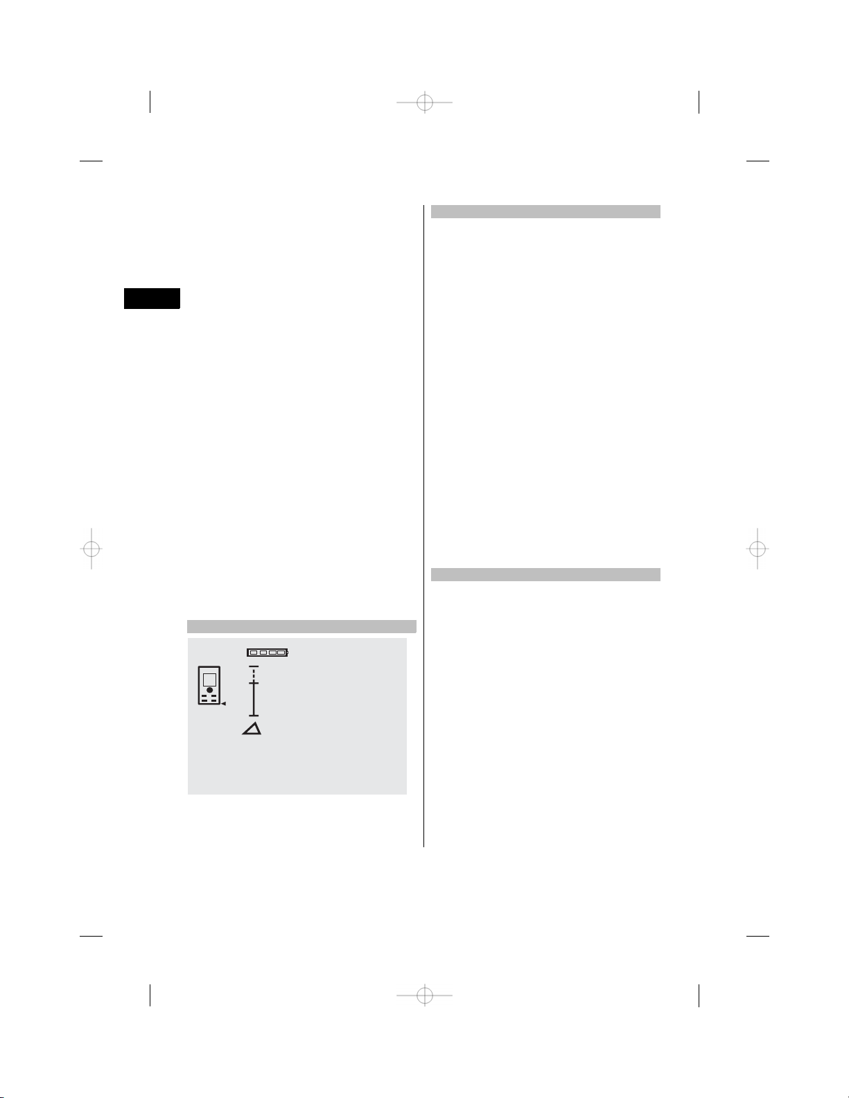
2.9 Battery condition indicator
Number of segments shown Charge status in %
4 = 100 % capacity
3 = 75 % capacity
2 = 50 % capacity
1 = 25 % capacity
0 Fully discharged
2.10 Items supplied as standard
1 PD 42 laser range meter
1 Hand strap
1 PDA 50 target plate
2 Batteries
1 Battery compartment key
1 Operating instructions
1 Manufacturer’s certificate
2.11 PUA 60 laser visibility glasses
The laser visibility glasses have no protective function and thus do not protect the eyes from laser beams. As
these glasses limit color vision they must not be worn by persons driving on a public road and must not be
used to look directly into the sun.
The PUA 60 laser visibility glasses improve laser beam visibility considerably.
en
2.12 PDA 50 / 51 / 52 target plate
The PDA 50 target plate is made of durable plastic with a special reflective coating. Use of the target plate is
recommended at distances greater than 10 m in poor light conditions.
The PDA 51 target plate has no reflective coating and its use is recommended in poor light conditions and at
short distances. The PDA 52 target plate is equipped with the same reflective coating as the PDA 50 but is
considerably larger in size (A4 format, 210 x 297 mm). This makes it much easier to aim the tool at the target
plate over long distances.
NOTE
For reliable distance measurements, care should be taken to ensure that the laser beam strikes the target plate
at right angles as far as possible. The laser spot on the target plate and the measuring reference point (starting
point) may otherwise be in different planes (parallax error).
29
Page 8

NOTE
When the target plate is used and very high accuracy is required, 1.2 mm should be added to the measurement
obtained.
2.13 PDA 71 measuring extension
The measuring extension is made from aluminium and is equipped with a nonಣconductive plastic grip. The
screw on the measuring extension should be screwed into the threaded bush on the rear contact surface of
en
the PD 42. When the measuring extension is screwed onto the tool, the rear reference is then relocated to the
tip of the measuring extension, i.e. the rear reference is extended by 1270 mm (50 inches).
3. Insert tools, accessories
Target plate PDA 50
Target plate PDA 51
Target plate PDA 52
Measuring extension PDA 71
Hand strap PDA 60
Soft pouch
Laser visibility glasses PUA 60
PDA 65
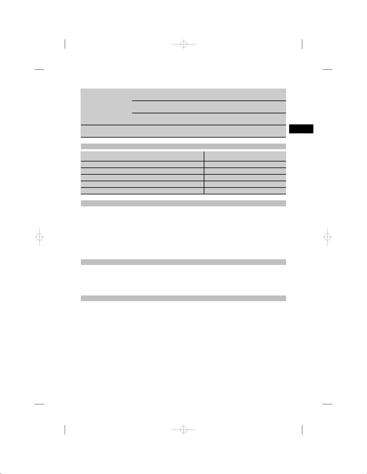
4. Technical data
Right of technical changes reserved.
Technical data Values
Power supply
Battery condition check Battery condition indicator with 4 segments showing
Measuring range 0.05…200 m
Typical measuring range without target plate Drywall panel, white: 100 m
Accuracy
Smallest unit displayed
Beam diameter Beam length 10 m: Max. 6 mm
Basic operating modes
Display Illuminated dotಣmatrix display with permanent
3V DC AAಣsize batteries
100%, 75%, 50%, 25% charge : No segments
shown: The batteries are exhausted
Concrete, dry: 70 m
Brick, dry: 50 m
Typically ±1.0 mm for single and continuous
measurement
1mm
Beam length 50 m: Max. 30 mm
Beam length 100 m: Max. 60 mm
Single measuring, continuous measuring, calculation/functions
indication of operating mode and battery condition
30
Page 9

Technical data Values
Laser
Optical sight Sideಣmounted, with laser reference
Automatic cutಣout Laser: 1 min
Battery life Max. number of measurements with laser
Operating temperature range -10…+50°C
Storage temperature -30…+70°C
Protection class (except battery compartment) IP 54 protection against dust and water jets
Weight without batteries 170 g
Dimensions 120 mm x 55 mm x 28 mm
Menu / units Distance Area Volume
m
cm
mm
In Inches, decimal Inchest Inchesu
In {/೩{/೩ inch Inchest Inchesu
In {/ೢ೧ {/ೢ೧ inch Inchest Inchesu
In {/ೣ {/ೣ inch Inchest Inchesu
Ft Feet, decimal Feett Feetu
Ft {/೩ Feetಣinchesಣ{/೩ Feett Feetu
Ft {/ೢ೧ Feetಣinches
Ft {/ೣ Feetಣinchesಣ{/ೣ Feett Feetu
Yd Yards, decimal Yardst Yardsu
Meters
Centimeters
Millimeters
ಣ{/ೢ೧ Feett Feetu
Visible 635 nm, Output power less than 1 mW: Laser
class 2
IEC 825ತ 1:2003CFR 21 § 1040 (FDA)
Tool: 10 min
beam switched on for a time of 10 s Alkaline 8,000…10,000 NiMH 6,000…8,000
IEC 529
mt mu
mt mu
mt mu
en
5. Safety rules
In addition to the information relevant to safety
given in each of the sections of these operating
instructions, the following points must be strictly
observed at all times.
5.1 Basic information concerning safety
a) Do not render safety devices ineffective and do
not remove information and warning notices.
b) Keep laser tools out of reach of children.
c) Failure to follow the correct procedures when
opening the tool may cause emission of laser
radiation in excess of class 2. Have the tool
repaired only at a Hilti service center.
d) Check that the tool functions correctly each time
before use.
e) Operation of the tool in the proximity of pregnant
women is not permissible.
f) Measurements taken from surfaces with low re-
flectivity in highly reflective surroundings may be
inaccurate.
g) Measurements taken through panes of glass or
other objects may be inaccurate.
h) Rapid changes in the conditions under which
the measurement is taken, e.g. persons walking
through the laser beam, may lead to inaccurate
results.
31
Page 10

i) Do not point the tool toward the sun or other
ಣ
ಣ
powerful light sources.
5.2 Proper organization of the workplace
a) Avoid unfavorable body positions when working
on ladders or scaffolding. Make sure you work
from a safe stance and stay in balance at all
en
times.
b) Check the measuring reference setting before
taking the measurement.
c) When the tool is brought into a warm environ-
ment from very cold conditions, or vice
allow it to become acclimatized before use.
d) As a precaution, check the previous settings and
adjustments you have made.
e) When setting up the tool with the aid of the
bubble level, view the bubble level at a slight
angle.
f) Secure the area in which you are working and
take care to avoid directing the beam towards
other persons or towards yourself when setting
up the tool.
g) Use the tool only within its specified limits.
h) Observe the accident prevention regulations ap-
plicable in your country.
5.3 Electromagnetic compatibility
Although the tool complies with the strict requirements of the applicable directives, Hilti cannot entirely rule out the possibility of the tool being subject
to interference caused by powerful electromagnetic
radiation, leading to incorrect operation. Check the
accuracy of the tool by taking measurements by other
means when working under such conditions or if you
are unsure. Likewise, Hilti cannot rule out the possibility of interference with other devices (e.g. aircraft
navigation equipment). The tool complies with the
requirements of class A; The possibility of interference occurring in a domestic environment cannot be
excluded.
5.4 General safety rules
a) Check the condition of the tool before use. If the
tool is found to be damaged, have it repaired at
a Hilti service center.
versa,
b) The user must check the accuracy of the tool
after it has been dropped or subjected to other
mechanical stresses.
c) Although the tool is designed for the tough con-
ditions of jobsite use, as with other measuring
instruments it should be treated with care.
d) Although the tool is protected to prevent entry
of dampness, it should be wiped dry each time
before being put away in its transport container.
5.5 Electrical
a) Keep the batteries out of reach of children.
b) Do not allow the batteries to overheat and do not
expose them to fire. The batteries may explode or
release toxic substances.
c) Do not charge the batteries.
d) Do not solder the batteries into the tool.
e) Do not discharge the batteries by short
ing. This may cause them to overheat and present
a risk of personal injury (burns).
f) Do not attempt to open the batteries and do not
subject them to excessive mechanical stress.
5.6 Laser classification
Depending on the version purchased, the tool complies with Laser Class 2 in accordance with IEC825ಣ
1:2003 / EN60825ಣ1:2003 and Class II in accordance
with CFR 21 § 1040 (FDA). This tool may be used
without need for further protective measures. The
eyelid closure reflex protects the eyes when a person looks into the beam unintentionally for a brief
moment. This eyelid closure reflex, however, may be
negatively affected by medicines, alcohol or drugs.
Nevertheless, as with the sun, one should not look
directly into sources of bright light. Do not direct the
laser beam toward persons.
5.7 Transport
Always remove the batteries before shipping the
tool.
circuit-
32
Page 11
6. Before use
6.1 Inserting the batteries 2
CAUTION
Do not use damaged batteries.
CAUTION
Always replace the complete set of batteries.
DANGER
Do not mix old and new batteries. Do not mix
batteries of different makes or types.
1. Unscrew the battery compartment cover from the
rear of the tool.
2. Remove the batteries from the packaging and
insert them in the tool.
NOTE Take care to observe correct polarity (see
symbols in battery compartment).
3. Check to ensure that the battery compartment
cover is closed securely.
6.2 Switching the tool on / off
1. The tool can be switched on by pressing either
the “On / off” button or the “Measure” button.
2. When the tool is switched off, press the “On / off”
button: The tool switches on.
The laser beam is switched off.
3. When the tool is switched on, press the “On / off”
button: The tool switches off.
4. Whenthe tool is switched off, press the “Measure”
button: The tool and the laser beam switch on.
6.3 First distance measurements
1. Press the “Measure” button once.
If switched off, the tool will be switched on and
the laser beam activated.
If the tool is already switched on, the laser beam
will be activated.
2. Aim the tool by positioning the visible laser spot
on a white surface at a distance of approx. 3 ಣ 10
m.
3. Press the “Measure” button again.
The distance will be displayed in less than a
second, e.g. 5.489 m.
You have just taken your first measurement with
the tool.
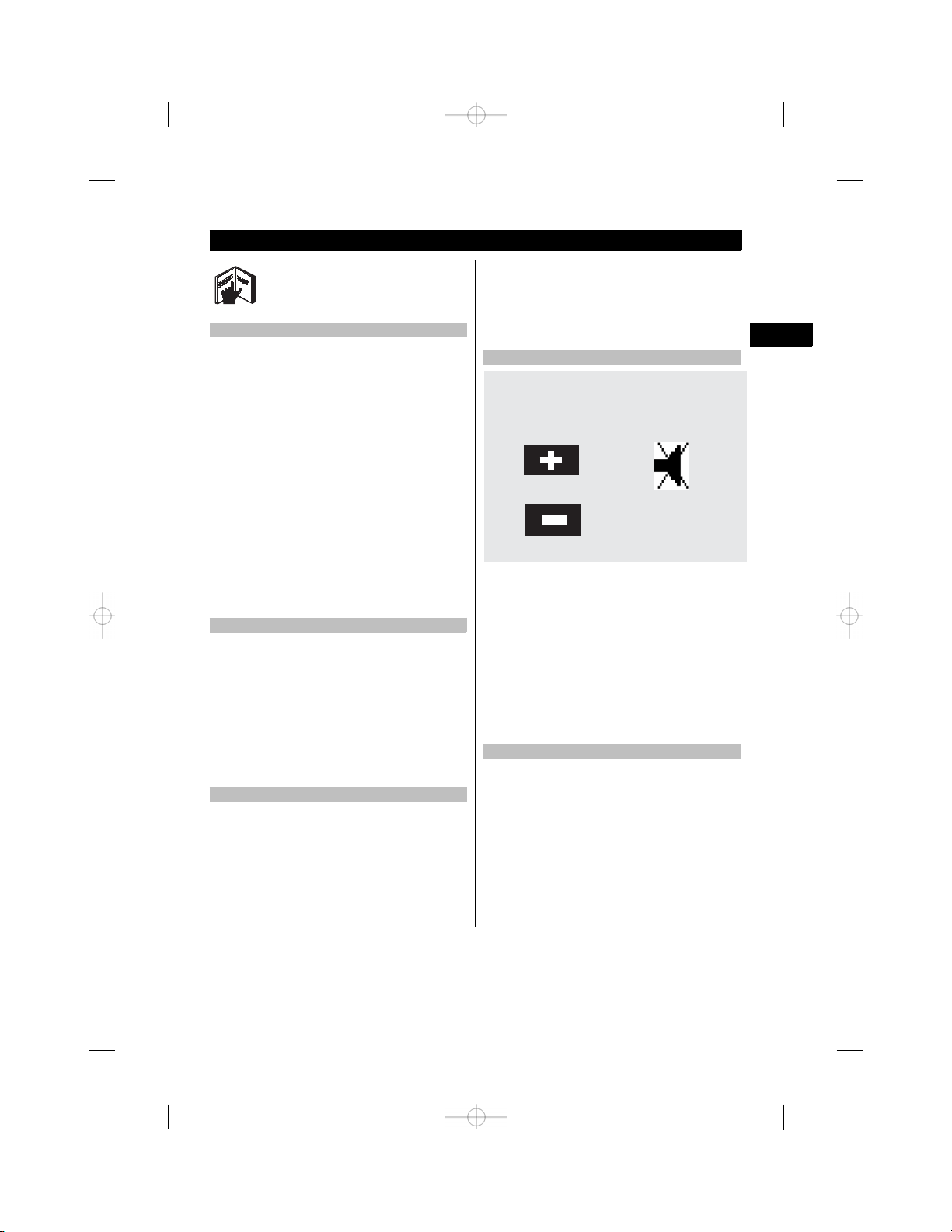
6.4 Settings menu
MENU
m
1. With the tool switched off, press the “On / off”
button for approx. 2 seconds to enter menu mode.
2. Press the “Plus” button to switch the beep signal
on or off.
3. Press the “Minus” button repeatedly to scroll
through the choice of units.
4. Press the “On / off” button briefly to close the
menu.
The tool is switched off and all the settings shown
will be saved.
6.5 Measuring references
NOTE
The tool can take measurements from 5 different
reference (contact) points. The “Reference” button on
the top left on the front of the tool is used to switch
between the front and rear references (front or rear
edge of the tool). The reference is set automatically
to the tip of the spike when the spike is folded
out through 180°. When the measuring extension
is screwed onto the tool at the rear (at the battery
compartment), this is detected automatically by the
tool and indicated by the long extension symbol in the
en
33
Page 12

display. The PDA 71 measuring extension can also be
fitted to the underside of the tool, but is not detected
automatically when in this position.
en
Front edge
Thread on underside
Rear edge
Spike
1. Press the “Measure” button to switch the laser
beam on and then aim the tool at the target.
2. Pressthe “Measure” button or the side “Measure”
button and aim the tool at the target until the laser
spot disappears from the optical sight.
The distance is shown in the display.
6.7 Measuring distances
NOTE
When the spike is folded back in, the measuring
reference is always reset to the rear edge of the tool
irrespective of how far the spike was folded out or to
which point on the tool the measuring reference was
previously set.
Distances can be measured from all stationary targets
without a highly reflective surface, i.e. concrete, stone,
wood, plastic, paper, etc. The use of prisms or other
highly reflective targets is not permissible and, if
attempted, may falsify the results.
6.7.1 Measuring distances step by step
NOTE
The range meter measures distances in a very short
time and simultaneously shows various information
in the display.
Switch the tool on by pressing the “On / off” button.
PDA 71 measuring extension screwed on at the rear
6.6 Optical sight 3
NOTE
The optical sight is useful when measuring distances
greater than 10 meters.
The builtಣin optical sight is particularly helpful outdoors and in situations where the laser spot is otherwise difficult to see or no longer visible. With the aid
of the optical sight, the tool can be aimed accurately
at targets even at great distance. When the tool is
switched on, the laser spot can be seen in the optical
sight. If the laser spot cannot be seen in the optical
sight, either the measurement has been successfully
completed or the laser beam has switched itself off
after the corresponding time interval. The axis of the
optical sight lies parallel to the axis of the laser beam.
34
----------
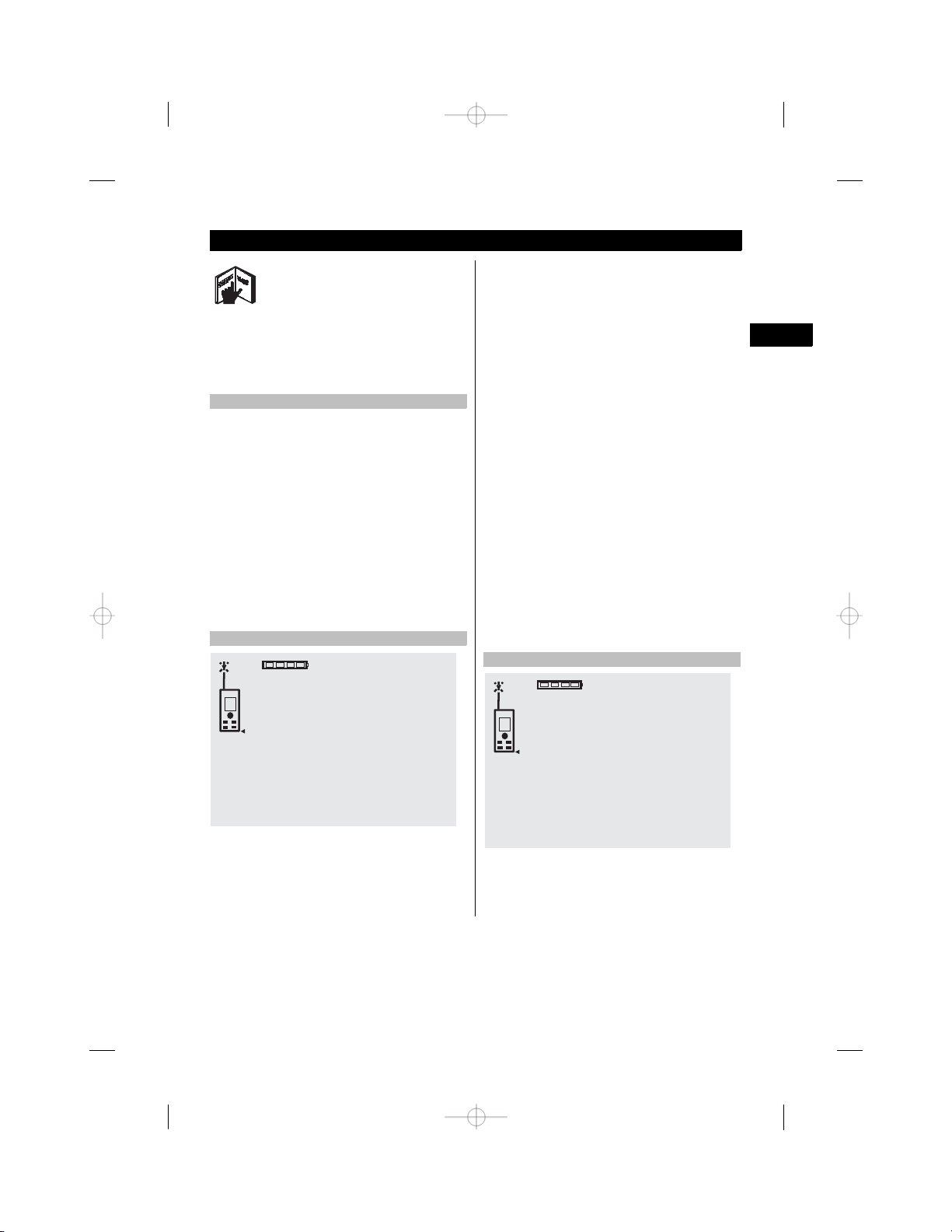
Press the “Measure” button once. The laser beam is
switched on and is visible in the form of a spot on the
target surface. This aiming mode is indicated in the
display by a blinking laser symbol.
m
Page 13

----------
Aim at the target. Press the “Measure” button once
again to measure the distance. The result usually
appears in the result line in less than a second and
the laser beam then switches off.
5.489
If further measurements are taken, up to three previously determined distances are shown in the intermediate result lines, i.e. a total of the last four measured
distances are shown.
5.489
12.349
m
m
m
m
The tool can, of course, be switched on again at any
time by pressing the “Measure” button. Pressing the
Cಣbutton clears all currently displayed values.
6.7.2 Measuring modes
Distances can be measured using two different measuring modes, i.e. single distance measuring or continuous measuring. Continuous measuring mode is
used for setting out given distances or lengths and
can also be used where distance measurement is
otherwise difficult, e.g. at corners, edges or in niches,
etc.
6.7.2.1 Single distance measuring (“Measure”
button)
1. Switch the laser beam on by pressing the “Measure” button.
2. Press the “Measure” button again.
The measured distance will be shown in the result
line at the bottom of the display in less than a
second.
6.7.2.2 Single distance measuring (“On /off”
button)
1. Switch the laser beam on by pressing the “On /
off” button.
2. Press the “Measure” button to switch the laser
beam on and then aim the tool at the target.
3. Press the “Measure” button again.
The measured distance will be shown in the result
line at the bottom of the display in less than a
second.
6.7.2.3 Continuous measuring (tracking)
NOTE
Continuous measuring is possible in all situations
where individual distances can be measured. This
applies also to functions, such as areas.
en
24.634
27.317
m
m
35
Page 14

1. Press the “Measure” button for about 2 seconds
to activate the continuous measuring mode.
NOTE When doing so, it doesn’t matter whether
the tool or the laser beam is switched on or
off. The tool will always switch to continuous
measuring mode.
During continuous measuring, distances are up-
en
dated in the result line at the rate of approx. 6 ಣ
10 measurements every second. The measuring
rate depends on reflectivity of the target surface.
If the beep signal is active, continuous measuring
is indicated by a beep signal approx. 2 ಣ 3 times
per second.
2. Measuring is stopped by pressing the “Measure”
button once again.
The last valid measurement is then shown in the
result line in the display.
6.7.3 Measuring from corners 45
The spike is used when measuring diagonally across
rooms or from inaccessible corners.
1. Fold out the spike through 180°.
The measuring reference is then set automatically
to the end of the spike. The range meter takes
the extended reference point into account and
corrects the measured distances accordingly.
2. Position the range meter with the spike at the
desired starting point for the measurement and
aim toward the target.
3. Press the “Measure” button.
The measured distance is shown in the display.
6.7.4 Measuring with the aid of target
objects 67
When taking measurements to outside corners (e.g.
on outside walls of buildings, perimeter fences, etc.),
boards, bricks or other suitable objects can be held
against the corner and used as the target. Use of
the PDA 50, PDA 51 or PDA 52 target plate is
recommended for long distances and in unfavorable
light conditions, e.g. in strong sunlight.
6.7.5 Measuring in bright conditions
We recommend use of the PDA 50, PDA 51 or PDA 52
target plate for long distances and in very bright light
conditions.
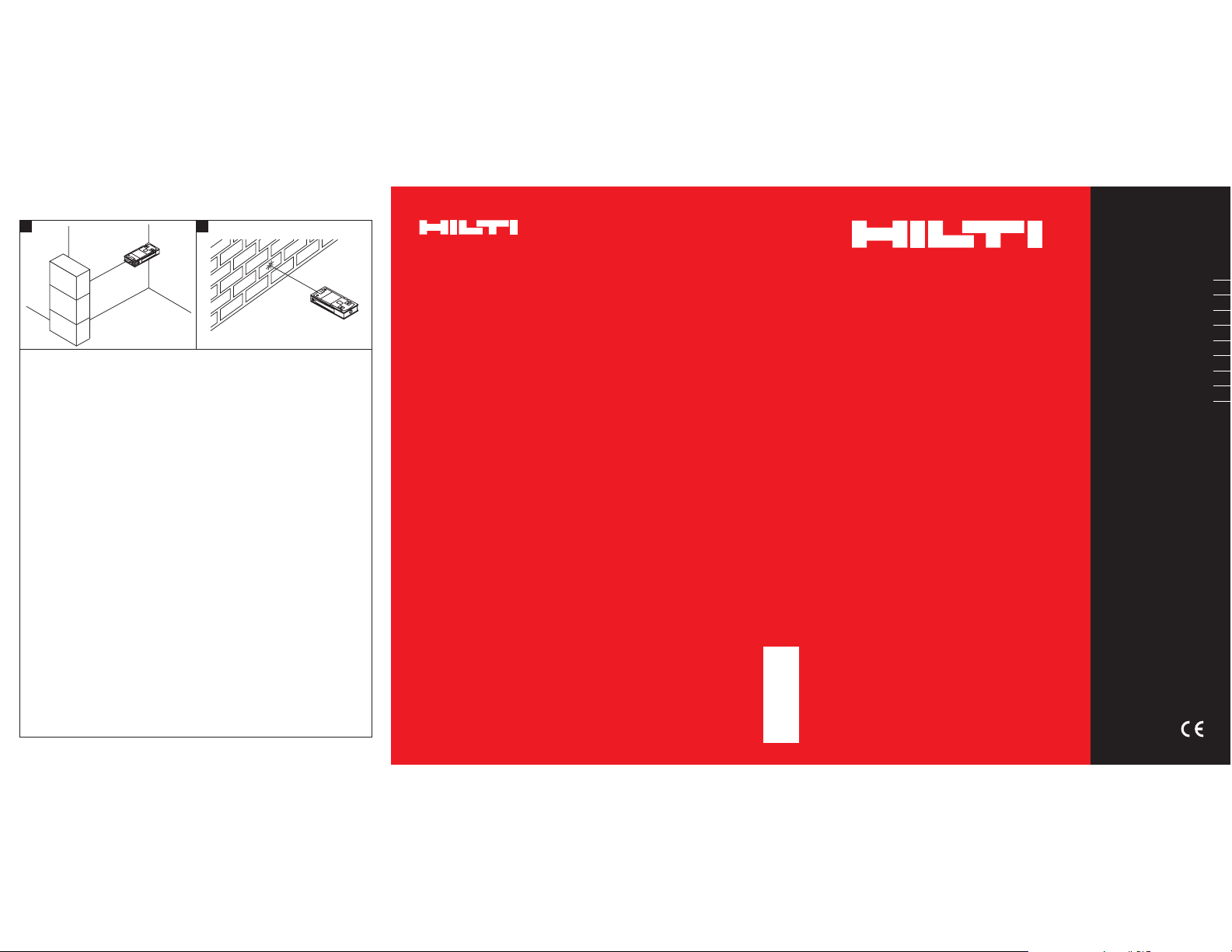
6.7.6 Taking measurements to rough surfaces 8
When measuring to rough surfaces, e.g. rough plaster
etc., an average distance value is measured with the
center of the laser spot weighted higher than the
edges of the laser spot.
6.7.7 Taking measurements to curved or
inclined surfaces
If the laser beam strikes the target surface at a very
narrow angle, the light reflected may be inadequate.
Conversely, too much light may be reflected toward
the tool in situations where the laser beam strikes
the target perpendicularly. We recommend use of the
PDA 50, PDA 51 or PDA 52 target plate in both of
these situations.
6.7.8 Taking measurements to wet or shiny
surfaces
As long as the range meter can be aimed directly at
the surface, the distance to the target will be reliably
measured. With highly reflective surfaces, a reduction
in range must be expected and the distance to the
actual point of reflection may be measured.
6.7.9 Taking measurements to transparent
surfaces
It is generally possible to measure distances to transparent or semiಣtransparent materials, e.g. liquids,
polystyrene foam, etc. Light penetrates these materials, however, and measuring errors may therefore
occur. Measuring errors may also occur when measurements are taken through glass or if objects are
present within the line of the laser beam.
6.7.10 Measuring range
6.7.10.1 Increased range
The range of the tool is generally increased when
measurements are taken in the dark, at dawn or dusk
and when the target and/or the tool is shaded from
bright light.
Use of the PDA 50, PDA 51 or PDA 52 target plate
also increases the range of the tool.
6.7.10.2 Reduced measuring range
Measuring range may be reduced in bright conditions,
e.g. in bright sunlight or when working under very
powerful floodlights.
The range of the tool may be reduced when measurements are taken through glass or when objects lie
within the path of the laser beam.
The range of the tool may be reduced when measurements are taken to mat green, blue or black surfaces
or to wet or shiny surfaces.
36
Page 15
7. Operation
NOTE
The direct control buttons are used for adding and
subtracting distances. All other functions are activated
by pressing the FNCಣbutton.
7.1 Distance measurements
NOTE
With all functions of the tool, each step in the operation is always indicated in the display.
NOTE
Continuous measuring mode can be used with all
functions in which individual distance measurement
is possible.
NOTE
If measuring errors occur during continuous measuring, and continuous measuring mode is canceled
by pressing the “Measure” button again, the last valid
measurement will be displayed.
7.2 Adding distances
1. Press the “Measure” button (the laser beam will
switch on).
2. Aim the range meter at the target.
3. Press the “Measure” button.
The first distance will be measured and displayed
(the laser then switches off).
4. Press the “Plus” button. The first distance is then
displayed in the middle result line and a plus sign
appears in the lower (intermediate) result line (the
laser beam switches on).
5. Aim the range meter at the target.
6. Press the “Measure” button.
The second distance is then measured and displayed in the lower (intermediate) result line. The
result of the addition is shown in the result line.
The current total of the distances is always shown
in the result line.
The procedure can be repeated until all distances
have been added.
7. To terminate the addition of distances, simply
measure a distance without first pressing the
“Plus” button.
All previous measuring and calculation results are
shown in the intermediate results lines.
8. Press the Cಣbutton to clear the display.
7.3 Subtracting distances
en
12.349
+ 5.489
17.838
Individual distances can be conveniently added. This
is useful, for example, for determining the total length
of the inner face of door or window openings or
for adding several individual distances that form a
perimeter.
m
m
m
3.947
- 3.322
0.625
Individual distances can be conveniently subtracted
from each other, e.g. in order to determine the distance between the underside of a pipe and the ceiling.
m
m
m
37
Page 16
This can be done by subtracting the distance between
the floor and the underside of the pipe from the
distance between the floor and the ceiling. If the
pipe diameter is subtracted, the result is the distance
between the top of the pipe and the ceiling.
1. Press the “Measure” button (the laser beam
switches on).
en
2. Aim the range meter at the target.
3. Press the “Measure” button. The first distance
will be measured and displayed (the laser then
switches off).
4. Press the “Minus” button. The first distance is
then displayed in the middle result line and a
minus sign appears in the lower (intermediate)
result line (the laser beam switches on).
5. Aim the range meter at the target.
6. Press the “Measure” button.
The second distance is then measured and displayed in the lower (intermediate) result line.
The result of the subtraction is shown in the result
line.
The current difference in distance is always shown
in the result line.
The procedure can be repeated until all distances
have been subtracted.
7. To terminate the subtraction of distances, simply
measure a distance without first pressing the
“Minus” button.
All previous measuring and calculation results are
shown in the intermediate results lines.
8. Press the Cಣbutton to clear the display.
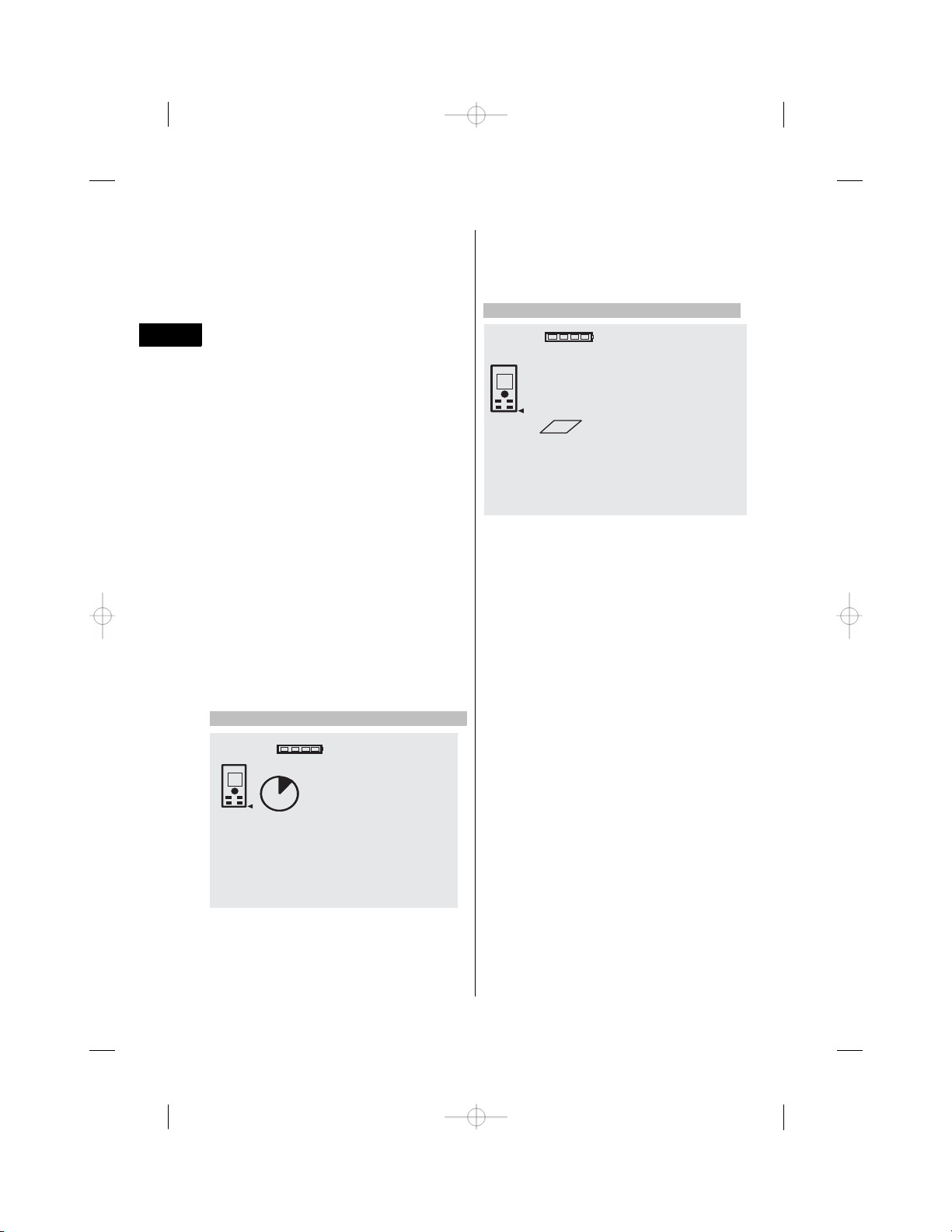
7.4 Timer
10s
4.347
m
button. A beep sound is emitted every second up to
about 4 seconds before the timer triggers the tool.
The last 4 seconds are counted down by a double
beep every second.
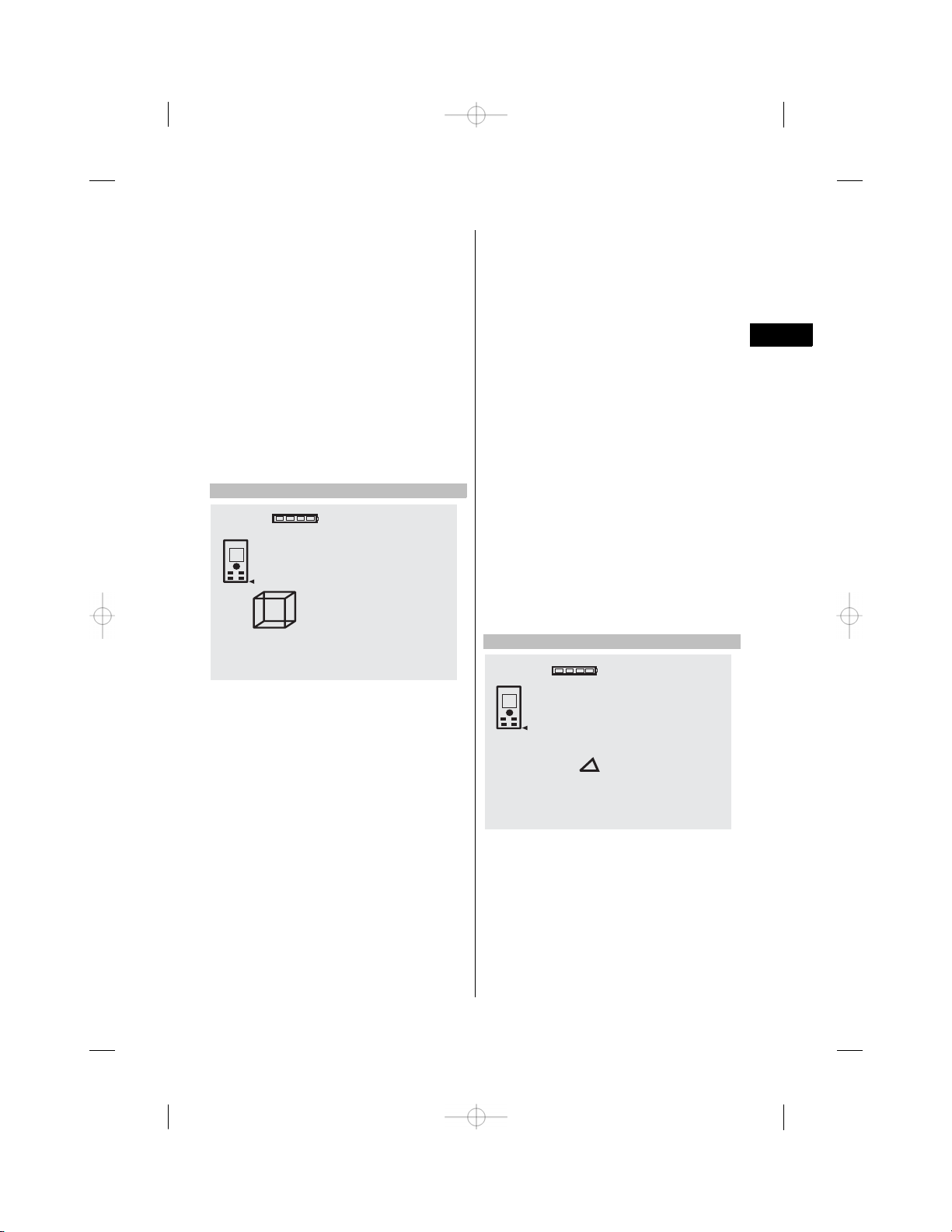
7.5 Measuring areas
m
5.489
5.489
12.349
12.349
67.784
67.784
Each step of the area measurement operation is
indicated graphically in the display. For example,
to determine the floor area of a room, proceed as
follows:
1. Pressthe FNCಣbutton to activate the area function.
NOTE When the area function is activated, the
laser beam is already switched on.
2. Aim the range meter at the target.
3. Press the “Measure” button.
The width of the room is measured and the value
displayed.
The graphic display automatically prompts you to
measure the length of the room.
4. Aim the tool at the next target to obtain the length
of the room.
5. Press the “Measure” button.
The second distance is then measured, the area
calculated immediately and the result is displayed
in the result line.
Both distances used for the area calculation are
shown in the intermediate result lines and can
be noted down conveniently at the end of the
operation.
m
m
m
m
m
3
2
The timer function works like the selfಣtimer on a
camera. The “Plus” and “Minus” buttons can be used
to adjust the timer interval to one of the three settings:
5, 10 or 20 seconds. To activate the timer, press the
“Measure” button. To stop the timer, press the Cಣ
38
Page 17
6. The Cಣbutton can be pressed at any time to
stop the measuring operation. Each measurement
can then be cleared, one after the other, and
measuring restarted.
NOTE If the Cಣbutton is pressed several times
or the FNCಣbutton is pressed, the function will be
canceled or, respectively, restarted.
NOTE If the second distance is measured using
continuous measuring mode (tracking), the result
of the area calculation is updated continuously.
This allows parts of the area to be included/
excluded.
NOTE After calculation of an area, the “Plus”
button can be pressed to add another area or,
respectively, the “Minus” button used to subtract
an area.
7.6 Measuring volumes
5.489
12.349
24.634
m
m
m
8. Aim the tool at the next target to obtain the height
of the room.
9. Press the “Measure” button.
The volume is calculated and shown in the result
line in the display as soon as the height of the
room has been measured.
All three distances used for the volume calculation
are shown in the intermediate result lines and can
be noted down conveniently at the end of the
operation.
10. The Cಣbutton can be pressed at any time to
stop the measuring operation. Each measurement
can then be cleared, one after the other, and
measuring restarted.
NOTE If the Cಣbutton is pressed several times
or the FNCಣbutton is pressed, the function will be
canceled or, respectively, restarted.
NOTE If the third distance is measured using
continuous measuring mode (tracking), the result
of the volume calculation is updated continuously.
This allows parts of the volume to be included/
excluded.
NOTE After calculation of a volume, the “Plus”
button can be pressed to add another volume or,
respectively, the “Minus” button used to subtract
a volume.
en
3
1669.783
Each step of the volume measurement operation is
indicated graphically in the display. For example, to
determine the volume of a room, proceed as follows:
1. Press the FNCಣbutton to activate the volume function. A volume can be determined in a single
measuring operation.
NOTE When the volume function is activated, the
laser beam is already switched on.
2. Aim the range meter at the target.
3. Press the “Measure” button.
The width of the room is measured and the value
displayed.
4. The graphic display automatically prompts you to
measure the length of the room.
5. Aim the tool at the next target to obtain the length
of the room.
6. Press the “Measure” button.
The length of the room is measured and the value
displayed.
7. Press the “Measure” button.
m
7.7 Measuring using the “Min/max” function
MAX 8.642
MIN 5.123
3.519
4.347
The “Maximum” function is used mainly to determine
the length of diagonals, while the “Minimum” function
is used to check parallels and set up objects parallel
to each other, or to take measurements in situations
where access is difficult. The “Maximum” function
makes use of continuous measuring mode. The value
shown in the display is updated whenever the measured distance increases. The “Minimum” function
also makes use of continuous measuring mode. The
value shown in the display is updated whenever
m
m
m
m
39
Page 18
the measured distance decreases. By combining the
“Maximum” and “Minimum” functions, differences in
distance can be determined very quickly, easily and
reliably. The distance between a pipe and ceiling, or
the distance between two objects even in inaccessible
locations, can thus be easily and reliably determined.
1. Press the FNCಣbutton to activate the “Min/max”
en
function.
NOTE When the “Min/max” function is activated,
the laser beam is already switched on.
2. Aim the range meter at the target.
3. Press the “Measure” button.
Continuous measuring then begins.
The values shown in the MIN and MAX display
areas are then updated whenever the measured
distance increases or decreases.
4. Press the “Measure” button to stop measuring.
The maximum distance, minimum distance and
the difference between minimum and maximum
are then shown in the display.
5. The Cಣbutton can be pressed at any time to stop
the last measuring operation, clear the result and
restart measuring.
NOTE If the Cಣbutton is pressed several times
or the FNCಣbutton is pressed, the function will be
canceled or, respectively, restarted.
NOTE Further “Undo” steps are not possible.
If the Cಣbutton is pressed several times or the
FNCಣbutton pressed once, the function will be
canceled.
7.8 Measuring / setting out
5.123
+ 3.519
1.604
The tool can be used to indicate given distances, e.g.
when setting out and marking the position of drywall
framing.
7.8.1 Setting out using a measured distance
1. Press the FNCಣbutton to activate the “Setting out”
function.
NOTE When the “Setting out” function is activated, the laser beam is already switched on.
2. Aim the range meter at the target.
3. Press the “Measure” button.
The initial distance, i.e. the distance to be transferred, is then measured and shown in the uppermost intermediate result line.
4. Press the “Measure” button.
The tool begins measuring in continuous measuring mode.
The difference between the currently measured
distance (see result line) and the initial distance
is shown in the lowest intermediate result line.
5. Move the tool back and forth until the difference
shown is as close to zero as is required for your
purpose.
6. The Cಣbutton can be pressed at any time to stop
the last measuring operation, clear the result and
restart measuring.
NOTE Further “Undo” steps are not possible.
If the Cಣbutton is pressed several times or the
FNCಣbutton pressed once, the function will be
canceled.
7.8.2 Setting out given distances
1. Press the FNCಣbutton to activate the “Setting out”
function.
NOTE When the “Setting out” function is activated, the laser beam is already switched on.
2. Enter the initial distance by pressing the “Plus”
button.
m
m
m
NOTE Pressing the “Plus” button briefly causes
the last digit to change (increase) by 1. Pressing
and holding the “Plus” button causes the digits to
change at a faster rate. The longer the button is
pressed, the faster the digits change. The “Minus”
button functions in the same way as the “Plus”
button, except that the digits decrease.
3. Press the “Measure” button.
The tool begins measuring in continuous measuring mode.
The difference between the currently measured
distance (see result line) and the initial distance
is shown in the lowest intermediate result line.
40
Page 19

4. Move the tool back and forth until the difference
shown is as close to zero as is required for your
purpose.
5. The Cಣbutton can be pressed at any time to stop
the last measuring operation, clear the result and
restart measuring.
NOTE Further “Undo” steps are not possible.
If the Cಣbutton is pressed several times or the
FNCಣbutton pressed once, the function will be
canceled.
7.9 Painter’s area
+
27.317
5.489
12.349+
m
m
m
2
6. Once all wall lengths have been added together,
press the “Measure” button again after taking
the last measurement and when the total of all
measurements is shown in the result line at the
bottom of the display.
The total length is transferred to the top intermediate result line and a multiplication symbol is
shown in the line below.
7. Now measure the height of the walls (= height of
the room).
The total wall area of the room is shown in the
result line at the bottom of the display.
8. The Cಣbutton can be pressed at any time to stop
the last measuring operation, clear the result and
restart measuring.
NOTE Further “Undo” steps are not possible.
If the Cಣbutton is pressed several times or the
FNCಣbutton pressed once, the function will be
canceled.
NOTE The “Minus” button can be used to subtract
certain distances, e.g. dimensions of windows or
doors. The “Plus” and “Minus” buttons can be
used alternately at any time.
en
The painter’s area function is used, for example, to
determine the surface area of the walls in a room.
This is done by determining the total length of all
walls and multiplying this figure by the height of the
room.
1. Press the FNCಣbutton to activate the painter’s area
function.
NOTE When the painter’s area function is activated, the laser beam is already switched on.
2. Measure the length of the first wall.
The length is shown in the top intermediate result
line.
3. Press the “Plus” button and measure the next
length.
The sum of the two lengths is shown in the results
line.
4. Press the “Plus” button again to make the tool
ready to measure the next length.
The total length is then displayed in the top
intermediate result line.
5. Measure the third length and, if necessary, any
further lengths.
7.10 Indirect measurements
A distance can be measured indirectly by taking
several measurements and the result then calculated
using the Pythagoras rule. The indirect measurement
functions are accessed by pressing the FNCಣbutton.
Three functions are available for use:
The “Single Pythagoras” function using a triangle with
two measured distances.
The “Double Pythagoras” function with 2 adjoining
triangles.
The “Combined Pythagoras” function using 2 part
triangles.
NOTE
A reduced level of accuracy, much lower than the
level of accuracy of the tool itself, must generally
be expected when the indirect measuring method is
used. In order to obtain the best results, care must
be taken regarding the geometry of the situation (i.e.
right angles and triangle relationships). Best results
are obtained when the tool is aimed carefully at the
corners of the object, when all points are within the
41
Page 20

same plane and when the measurements are taken
from a location not too far away from the object.
7.10.1 The “Single Pythagoras” method
en
8.642
5.123
7.10.2 The “Double Pythagoras” method
8.642
m
m
5.123
5.430
m
m
m
6.962
Follow the symbols in the display. The blinking side
of the triangle indicates the measurement to be taken.
When the 2 required distances have been measured,
the result is then calculated and shown in the result
line in the lower area of the display.
1. Press the FNCಣbutton to activate the “Single Pythagoras” function.
NOTE When the “Single Pythagoras” function is
activated, the laser beam is already switched on.
2. Aim the tool at the target as indicated by the
symbol in the display.
Press the “Measure” button.
3. The graphic display automatically prompts you to
measure the shorter distance.
4. Aim the laser spot at the target and press the
“Measure” button.
NOTE Please note that this distance is measured
in continuous measuring mode in order to ensure
that the shortest distance to the target (at right
angles) is measured reliably.
When the second measurement has been taken,
the tool then immediately calculates the opposite
“indirect distance”.
The system checks whether the geometric relationship allows a result to be calculated. An
invalid result, due to inappropriate geometry, is
indicated by the result line blinking (broken line).
In this case, one or both of the distances must be
remeasured.
m
8.76
Follow the symbols in the display. The blinking side
of the triangle indicates the measurement to be taken.
When the 3 required distances have been measured,
the result is then calculated and shown in the result
line at the bottom of the display.
1. Press the FNCಣbutton to activate the “Double
Pythagoras” function.
NOTE When the “Double Pythagoras” function is
activated, the laser beam is already switched on.
2. Aim the tool at the target as indicated by the
symbol in the display.
Press the “Measure” button.
3. The graphic display automatically prompts you to
measure the middle distance.
NOTE Please note that this distance is measured
in continuous measuring mode in order to ensure
that the shortest distance to the target (at right
angles) is measured reliably.
4. Sweep the laser spot slowly over the target at the
point where the distance is shortest and then stop
measuring by pressing the “Measure” button.
After the last distance has been measured, the
tool immediately calculates the opposite “indirect
distance”.
The system checks whether the geometric relationship allows a result to be calculated. An
invalid result, due to inappropriate geometry, is
indicated by the result line blinking (broken line).
In this case, one or more of the distances must
be remeasured.
m
42
Page 21

7.10.3 The “Combined Pythagoras” method
7.11 Saving the current measurement
7.823
4.762
3.894
4.044
Follow the symbols in the display. The blinking side
of the triangle indicates the measurement to be taken.
When the 3 required distances have been measured,
the result is then calculated and shown in the result
line at the bottom of the display.
1. Press the FNCಣbutton to activate the “Combined
Pythagoras” function.
NOTE When the “Combined Pythagoras” function
is activated, the laser beam is already switched
on.
2. Aim the tool at the target as indicated by the
symbol in the display.
Press the “Measure” button.
3. The graphic display automatically prompts you to
measure the middle distance.
4. The graphic display prompts you to measure the
last distance.
NOTE Please note that this distance is measured
in continuous measuring mode in order to ensure
that the shortest distance to the target (at right
angles) is measured reliably.
After the last distance has been measured, the
tool immediately calculates the opposite “indirect
distance”.
The system checks whether the geometric relationship allows a result to be calculated. An
invalid result, due to inappropriate geometry, is
indicated by the result line blinking (broken line).
In this case, one or more of the distances must
be remeasured.
m
m
m
m
5.489
12.349
24.634
27.317
If several distance measurements have been taken,
up to 3 previous measurements are shown in the
intermediate result lines in the standard display, i.e.
in total, the 4 previous measurements are shown and
saved. The last measurement taken is shown in the
lowest line of the display.
7.12 Data memory
+
5.489
12.349+
m
m
m
m
m
m
M
4
27.317
The tool saves measurements and the results of
calculations continuously while in operation. A total
of up to 30 values, including graphic symbols, are
saved in this way. The complete set of information
displayed is saved in the following situations:
A function provides a valid result when:
m
2
en
43
Page 22

A valid distance is measured and shown in the standard display:
Distances are added using the “Plus” button – the
last total is saved in each case.
Distances are subtracted using the “Minus” button –
the last total is saved in each case.
NOTE
en
When data memory is already filled with the 30
previous sets of displayed data, the “oldest” set of
data is deleted when a new set of displayed data is
saved.
7.12.1 Clearing data memory
Data memory can be completely cleared by pressing
the Cಣbutton for approx. 2 seconds while data memory
is displayed.
---------
---------
M
---------
m
m
m
1
---------
m
8. Care and maintenance
8.1 Cleaning and drying
1. Blow dust off the lenses.
2. Do not touch the glass or the filter with the fingers.
3. Use only a clean, soft cloth for cleaning. If necessary, moisten the cloth slightly with pure alcohol
or a little water.
NOTE Do not use any other liquids as these may
damage the plastic components.
4. The temperature limits for storage of your equipment must be observed, especially in winter /
summer.
8.2 Storage
Remove the tool from its case if it has become wet.
The tool, its carrying case and accessories should
be cleaned and dried (at maximum 40°C / 104°F).
Repack the equipment only once it is completely dry.
Check the accuracy of the equipment before it is used
after a long period of storage or transportation.
Remove the batteries from the tool before storing it
for a long period. Leaking batteries may damage the
tool.
8.3 Transport
Use the Hilti toolbox or packaging of equivalent quality
for transporting or shipping your equipment.
CAUTION
Always remove the batteries before shipping the
tool.
8.4 Calibration and adjustment
8.4.1 Calibration
Monitoring of measuring equipment for users certified in accordance with ISO 9000X: As specified
in ISO 900X, you may carry out the inspection and
testing of the PD 42 laser range meter yourself (see
ISO 17123ಣ4: Field Process for Accuracy Examination
44
Page 23

of Geodetic Instruments: Part 6, Closeಣrange Optoಣ
electrical Range Meters).
1. Select a readily accessible measuring distance of
a known length (approx. 1 to 5 meters / 3 to
15 feet) which does not change over time and
measure the same distance 10 times.
2. Determine the mean deviation from the known
distance. This value should be within the specified
accuracy tolerance for the tool.
3. Keep a record of this value and note the date when
the next test is due.
Repeat this test at regular intervals as well as
before and after important measuring tasks.
Apply a test and inspection confirmation sticker
to the PD 42 and keep a record of the entire
monitoring, test and inspection procedure and
the results.
Please refer to the technical data contained in
the operating instructions and the information
concerning measuring accuracy.
8.4.2 Adjustment
To ensure that the laser range meter is adjusted
correctly, we recommend that it is returned to a Hilti
Service Center for calibration. Accurate adjustment of
the tool will be confirmed by a calibration certificate.
8.4.3 Hilti calibration service
We recommend that the tool is checked by the Hilti
calibration service at regular intervals in order to
verify its reliability in accordance with standards and
legal requirements.
Use can be made of the Hilti calibration service
at any time, but checking at least once a year is
recommended.
The calibration service provides confirmation that the
tool is in conformance, on the day it is tested, with
the specifications given in the operating instructions.
The tool will be readjusted if deviations from the
manufacturer’s specification are found. After checking and adjustment, a calibration sticker applied to
the tool and a calibration certificate provide written
verification that the tool operates in accordance with
the manufacturer’s specification.
Calibration certificates are always required by companies certified according to ISO 900x.
Your local Hilti Center or representative will be pleased
to provide further information.
9. Troubleshooting
Fault Possible cause Remedy
The tool can’t be switched on.
No distances displayed by the
tool.
Frequent error messages or
the tool doesn’t measure.
Measuring reference not set
to the spike.
The batteries are exhausted. Replace the batteries.
Incorrect battery polarity. Insert the batteries correctly and
The button is faulty. Return the tool to Hilti for repair.
“Measure” button was not pressed. Press the “Measure” button.
Faulty display.
The target surface is too brightly lit
by the sun.
The target surface is too shiny. Take measurements from less shiny
The target surface is too dark.
Bright sunlight towards the tool. Use the PDA 50/ PDA 51/ PDA 52
The spike is not folded out fully. Fold the spike out fully.
The spike is faulty. Return the tool to Hilti for repair.
close the battery compartment
cover.
Return the tool to Hilti for repair.
Measure from the other direction –
sun from behind.
surfaces.
Use the PDA 50/ PDA 51/ PDA 52
target plate.
target plate.
en
45
Page 24
Fault Possible cause Remedy
Measuring reference not set
to the extension.
No result obtained using
en
Pythagoras function.
No result obtained using
functions.
The measuring extension is not
screwed in fully.
Dirt or foreign matter in the threaded
bush.
A distance is missing. Measure the missing distance(s).
The difference between the dis-
tances is insufficient.
The result cannot be calculated
(geometry incorrect).
Distance measurements are missing.
Numerical value of the result is too
high (cannot be displayed).
Screw the measuring extension in
fully.
Clean the threaded bush.
The distance to be calculated should
be greater than {/ of the distances
measured.
Move as close as possible to the
object to be measured. Triangles
are possibly too small.
Measure the missing distance(s).
Change to a larger unit.
10. Disposal
WARNING
Improper disposal of the equipment may have serious consequences:
The burning of plastic components generates toxic fumes which may present a health hazard.
Batteries may explode if damaged or exposed to very high temperatures, causing poisoning, burns, acid burns
or environmental pollution.
Careless disposal may permit unauthorized and improper use of the equipment. This may result in serious
personal injury, injury to third parties and pollution of the environment.
Most of the materials from which Hilti tools or appliances are manufactured can be recycled. The materials must
be correctly separated before they can be recycled. In many countries, Hilti has already made arrangements
for taking back old tools and appliances for recycling. Ask Hilti customer service or your Hilti representative
for further information.
For EC countries only
Disposal of electric tools together with household waste is not permissible.
In observance of European Directive 2002/96/EC on waste electrical and electronic equipment
and its implementation in accordance with national law, electric tools that have reached the end
of their life must be collected separately and returned to an environmentally compatible recycling
facility.
Dispose of the batteries in accordance with national regulations.
46
Page 25

11. Manufacturer’s warrantyಣtools
Hilti warrants that the tool supplied is free of defects
in material and workmanship. This warranty is valid
so long as the tool is operated and handled correctly,
cleaned and serviced properly and in accordance with
the Hilti Operating Instructions, and the technical
system is maintained. This means that only original
Hilti consumables, components and spare parts may
be used in the tool.
This warranty provides the freeಣofಣcharge repair or
replacement of defective parts only over the entire
lifespan of the tool. Parts requiring repair or replacement as a result of normal wear and tear are not
covered by this warranty.
12. EC declaration of conformity
Designation: Laser range meter
Type: PD 42
Year of design:
We declare, on our sole responsibility, that this
product complies with the following directives and
standards: EN 50081ತ1, EN 61000ತ6ತ2, 89/336/EEC.
2006
Additional claims are excluded, unless stringent national rules prohibit such exclusion. In particular,
Hilti is not obligated for direct, indirect, incidental
or consequential damages, losses or expenses in
connection with, or by reason of, the use of, or
inability to use the tool for any purpose. Implied
warranties of merchantability or fitness for a particular purpose are specifically excluded.
For repair or replacement, send the tool or related
parts immediately upon discovery of the defect to
the address of the local Hilti marketing organization
provided.
This constitutes Hilti’s entire obligation with regard
to warranty and supersedes all prior or contemporaneous comments and oral or written agreements
concerning warranties.
Hilti Corporation
Bodo Baur Tassilo Deinzer
Quality Manager Head BU Measuring Systems
BA Electric Tools & Accessories BU Measuring Systems
01 2007 01 2007
en
47
 Loading...