

Page 1

Network Camera
User Manual
V5.2.0
UD.6L0201D1514A01
Page 2

User Manual of Network Camera
Type
Model
Type I
DS-2CD20 Series Camera
Type II
DS-2CD21 Series Camera, DS-2CD11 Series Camera
Type III
DS-2CD22 Series Camera
Type IV
DS-2CD23 Series Camera
Type V
DS-2CD24 Series Camera, DS-2CD14 Series Camera
Type VI
DS-2CD25 Series Camera, DS-2CD15 Series Camera
Type VII
DS-2CD26 Series Camera
Type VIII
DS-2CD27 Series Camera
Type IX
DS-2CD2Q Series Camera
Type X
DS-2CD2A Series Camera
Type XI
DS-2CD2T Series Camera
Type XII
DS-2CD2C Series Camera
Type XIII
DS-2CD2D Series Camera
Type XIV
DS-2CD40 Series Camera, iDS-2CD60 Series Camera
Type XV
DS-2CD41 Series Camera, iDS-2CD61 Series Camera
Type XVI
DS-2CD42 Series Camera
Type XVII
DS-2CD43 Series Camera
Type XVIII
DS-2CD45 Series Camera
Type XIX
DS-2CD46 Series Camera
Type XX
DS-2CD48 Series Camera
Type XXI
DS-2CD4A Series Camera
Type XXII
DS-2CD64 Series Camera
Type XXIII
DS-2CD65 Series Camera
Thank you for purchasing our product. If there are any questions, or requests, please
do not hesitate to contact the dealer.
This manual applies to Network Camera (V5.2.0), and the detailed models are list
below.
1
Page 3

User Manual of Network Camera
This manual may contain several technical incorrect places or printing errors, and the
content is subject to change without notice. The updates will be added to the new
version of this manual. We will readily improve or update the products or procedures
described in the manual.
DISCLAIMER STATEMENT
“Underwriters Laboratories Inc. (“UL”) has not tested the performance or reliability
of the security or signaling aspects of this product. UL has only tested for fire, shock
or casualty hazards as outlined in UL’s Standard(s) for Safety, UL60950-1. UL
Certification does not cover the performance or reliability of the security or signaling
aspects of this product. UL MAKES NO REPRESENTATIONS, WARRANTIES OR
CERTIFICATIONS WHATSOEVER REGARDING THE PERFORMANCE OR
RELIABILITY OF ANY SECURITY OR SIGNALING RELATED FUNCTIONS
OF THIS PRODUCT”.
2
Page 4
User Manual of Network Camera
Regulatory Information
FCC Information
FCC compliance: This equipment has been tested and found to comply with the
limits for a digital device, pursuant to part 15 of the FCC Rules. These limits are
designed to provide reasonable protection against harmful interference when the
equipment is operated in a commercial environment. This equipment generates, uses,
and can radiate radio frequency energy and, if not installed and used in accordance
with the instruction manual, may cause harmful interference to radio communications.
Operation of this equipment in a residential area is likely to cause harmful
interference in which case the user will be required to correct the interference at his
own expense.
FCC Conditions
This device complies with part 15 of the FCC Rules. Operation is subject to the
following two conditions:
1. This device may not cause harmful interference.
2. This device must accept any interference received, including interference that may
cause undesired operation.
EU Conformity Statement
This product and - if applicable - the supplied accessories too are
marked with "CE" and comply therefore with the applicable
harmonized European standards listed under the Low Voltage
Directive 2006/95/EC, the EMC Directive 2004/108/EC, the RoHS
Directive 2011/65/EU.
2012/19/EU (WEEE directive): Products marked with this symbol
cannot be disposed of as unsorted municipal waste in the European
Union. For proper recycling, return this product to your local
supplier upon the purchase of equivalent new equipment, or dispose
of it at designated collection points. For more information see:
www.recyclethis.info.
2006/66/EC (battery directive): This product contains a battery that
cannot be disposed of as unsorted municipal waste in the European
Union. See the product documentation for specific battery
information. The battery is marked with this symbol, which may
include lettering to indicate cadmium (Cd), lead (Pb), or mercury
(Hg). For proper recycling, return the battery to your supplier or to
a designated collection point. For more information see:
www.recyclethis.info.
3
Page 5
User Manual of Network Camera
Warnings Follow these safeguards to
prevent serious injury or death.
Cautions Follow these precautions to
prevent potential injury or material
damage.
Safety Instruction
These instructions are intended to ensure that the user can use the product correctly to
avoid danger or property loss.
The precaution measure is divided into ‘Warnings’ and ‘Cautions’:
Warnings: Serious injury or death may be caused if any of these warnings are
neglected.
Cautions: Injury or equipment damage may be caused if any of these cautions are
neglected.
Warnings:
Please adopt the power adapter which can meet the safety extra low voltage
(SELV) standard. And source with 12 VDC or 24 VAC (depending on models)
according to the IEC60950-1 and Limited Power Source standard.
If the product does not work properly, please contact your dealer or the nearest
service center. Never attempt to disassemble the camera yourself. (We shall not
assume any responsibility for problems caused by unauthorized repair or
maintenance.)
To reduce the risk of fire or electrical shock, do not expose this product to rain or
moisture.
This installation should be made by a qualified service person and should conform
to all the local codes.
Please install blackouts equipment into the power supply circuit for convenient
supply interruption.
Please make sure that the ceiling can support more than 50(N) Newton gravities if
the camera is fixed to the ceiling.
If the product does not work properly, please contact your dealer or the nearest
service center. Never attempt to disassemble the camera yourself. (We shall not
assume any responsibility for problems caused by unauthorized repair or
maintenance.)
4
Page 6

User Manual of Network Camera
Cautions:
Make sure the power supply voltage is correct before using the camera.
Do not drop the camera or subject it to physical shock.
Do not touch sensor modules with fingers. If cleaning is necessary, use a clean
cloth with a bit of ethanol and wipe it gently. If the camera will not be used for an
extended period of time, put on the lens cap to protect the sensor from dirt.
Do not aim the camera lens at the strong light such as sun or incandescent lamp.
The strong light can cause fatal damage to the camera.
The sensor may be burned out by a laser beam, so when any laser equipment is
being used, make sure that the surface of the sensor not be exposed to the laser
beam.
Do not place the camera in extremely hot, cold temperatures (the operating
temperature should be between -30°C ~ 60°C, or -40°C ~ 60°C if the camera
model has an “H” in its suffix), dusty or damp environment, and do not expose it
to high electromagnetic radiation.
To avoid heat accumulation, good ventilation is required for a proper operating
environment.
Keep the camera away from water and any liquid.
While shipping, the camera should be packed in its original packing.
Improper use or replacement of the battery may result in hazard of explosion.
Please use the manufacturer recommended battery type.
Notes:
For the camera supports IR, you are required to pay attention to the following
precautions to prevent IR reflection:
Dust or grease on the dome cover will cause IR reflection. Please do not remove
the dome cover film until the installation is finished. If there is dust or grease on
the dome cover, clean the dome cover with clean soft cloth and isopropyl alcohol.
Make certain the installation location does not have reflective surfaces of objects
too close to the camera. The IR light from the camera may reflect back into the
lens causing reflection.
The foam ring around the lens must be seated flush against the inner surface of
the bubble to isolate the lens from the IR LEDS. Fasten the dome cover to camera
body so that the foam ring and the dome cover are attached seamlessly.
5
Page 7

User Manual of Network Camera
Table of Contents
Chapter 1 System Requirement .................................................................................. 9
Chapter 2 Network Connection ............................................................................... 10
2.1 Setting the Network Camera over the LAN....................................................... 10
2.1.1 Wiring over the LAN ...................................................................................................... 10
2.1.2 Detecting and Changing the IP Address ......................................................................... 11
2.2 Setting the Network Camera over the WAN ...................................................... 12
2.2.1 Static IP Connection ....................................................................................................... 12
2.2.2 Dynamic IP Connection .................................................................................................. 13
Chapter 3 Access to the Network Camera ............................................................... 16
3.1 Accessing by Web Browsers ................................................................................ 16
3.2 Accessing by Client Software .............................................................................. 18
Chapter 4 Wi-Fi Settings .......................................................................................... 20
4.1 Configuring Wi-Fi Connection in Manage and Ad-hoc Modes ....................... 20
4.2 Easy Wi-Fi Connection with WPS function ....................................................... 24
4.3 IP Property Settings for Wireless Network Connection ................................... 27
Chapter 5 Live View ................................................................................................. 28
5.1 Live View Page ..................................................................................................... 28
5.2 Starting Live View ................................................................................................ 29
5.3 Recording and Capturing Pictures Manually ................................................... 30
5.4 Operating PTZ Control ....................................................................................... 30
5.4.1 PTZ Control Panel .......................................................................................................... 30
5.4.2 Setting / Calling a Preset................................................................................................. 31
5.4.3 Setting / Calling a Patrol ................................................................................................. 32
Chapter 6 Network Camera Configuration ............................................................. 34
6.1 Configuring Local Parameters............................................................................ 34
6.2 Configuring Time Settings .................................................................................. 36
6.3 Configuring Network Settings ............................................................................ 38
6.3.1 Configuring TCP/IP Settings .......................................................................................... 38
6.3.2 Configuring Port Settings ............................................................................................... 39
6.3.3 Configuring PPPoE Settings ........................................................................................... 40
6.3.4 Configuring DDNS Settings ........................................................................................... 40
6.3.5 Configuring SNMP Settings ........................................................................................... 44
6.3.6 Configuring 802.1X Settings .......................................................................................... 46
6.3.7 Configuring QoS Settings ............................................................................................... 47
6.3.8 Configuring UPnP™ Settings ......................................................................................... 47
6
Page 8

User Manual of Network Camera
6.3.9 Email Sending Triggered by Alarm ................................................................................ 48
6.3.10 Configuring NAT (Network Address Translation) Settings ............................................ 50
6.3.11 Configuring FTP Settings ............................................................................................... 51
6.3.12 Platform Access ................................................................................................ .............. 52
6.3.13 HTTPS Settings .............................................................................................................. 52
6.4 Configuring Video and Audio Settings ............................................................... 54
6.4.1 Configuring Video Settings ............................................................................................ 54
6.4.2 Configuring Audio Settings ................................................................ ............................ 56
6.4.3 Configuring ROI Encoding ............................................................................................. 57
6.4.4 Display Info. on Stream .................................................................................................. 59
6.5 Configuring Image Parameters .......................................................................... 59
6.5.1 Configuring Display Settings ......................................................................................... 59
6.5.2 Configuring OSD Settings .............................................................................................. 64
6.5.3 Configuring Text Overlay Settings ................................................................................. 66
6.5.4 Configuring Privacy Mask .............................................................................................. 67
6.5.5 Configuring Picture Overlay ........................................................................................... 68
6.6 Configuring and Handling Alarms ..................................................................... 69
6.6.1 Configuring Motion Detection........................................................................................ 69
6.6.2 Configuring Video Tampering Alarm ............................................................................. 75
6.6.3 Configuring Alarm Input ................................................................................................ 76
6.6.4 Configuring Alarm Output .............................................................................................. 77
6.6.5 Handling Exception ........................................................................................................ 78
6.6.6 Configuring Face Detection ............................................................................................ 79
6.6.7 Configuring Audio Exception Detection ........................................................................ 81
6.6.8 Configuring Line Crossing Detection ............................................................................. 82
6.6.9 Configuring Intrusion Detection ..................................................................................... 83
6.6.10 Configuring Defocus Detection ...................................................................................... 85
6.6.11 Configuring Scene Change Detection ............................................................................. 85
6.7 VCA Configuration .............................................................................................. 86
6.7.1 Behavior Analysis ........................................................................................................... 86
6.7.2 Face Capture ................................................................................................................... 92
6.7.3 Heat Map ........................................................................................................................ 96
6.7.4 People Counting ............................................................................................................. 98
Chapter 7 Storage Settings ..................................................................................... 102
7.1 Configuring NAS Settings ................................................................................. 102
7.2 Configuring Recording Schedule ...................................................................... 104
7.3 Configuring Snapshot Settings ......................................................................... 108
Chapter 8 People Counting .................................................................................... 111
Chapter 9 Playback ................................................................................................ 114
Chapter 10 Log Searching ................................................................................... 116
7
Page 9

User Manual of Network Camera
Chapter 11 Others ................................................................................................ 117
11.1 Managing User Accounts .................................................................................... 117
11.2 Authentication ..................................................................................................... 119
11.3 Anonymous Visit ................................................................................................ 120
11.4 IP Address Filter ................................................................................................. 121
11.5 Security Service .................................................................................................. 122
11.6 Viewing Device Information .............................................................................. 123
11.7 Maintenance ....................................................................................................... 124
11.7.1 Rebooting the Camera .................................................................................................. 124
11.7.2 Restoring Default Settings ............................................................................................ 124
11.7.3 Exporting / Importing Configuration File ................................................................ ..... 124
11.7.4 Upgrading the System................................................................................................... 125
11.8 RS-232 Settings ................................................................................................... 126
11.9 RS-485 Settings ................................................................................................... 127
11.10 Service Settings ................................................................................................... 127
Appendix .................................................................................................................... 128
Appendix 1 SADP Software Introduction ..................................................................... 128
Appendix 2 Port Mapping .............................................................................................. 131
8
Page 10

User Manual of Network Camera
Chapter 1 System Requirement
Operating System: Microsoft Windows XP SP1 and above version / Vista / Win7 /
Server 2003 / Server 2008 32bits
CPU: Intel Pentium IV 3.0 GHz to Core i7-4000 series or higher, depending on
different video resolutions
RAM: 1G or higher
Display: 1024×768 resolution or higher
Web Browser: Internet Explorer 7.0 and above version, Safari 5.02 and above
version, Mozilla Firefox 3.5 and above version and Google Chrome8 and above
versions.
9
Page 11
User Manual of Network Camera
Chapter 2 Network Connection
Before you start:
If you want to set the network camera via a LAN (Local Area Network), please
refer to Section 2.1 Setting the Network Camera over the LAN.
If you want to set the network camera via a WAN (Wide Area Network), please
refer to Section 2.2 Setting the Network Camera over the WAN.
2.1 Setting the Network Camera over the LAN
Purpose:
To view and configure the camera via a LAN, you need to connect the network
camera in the same subnet with your computer, and install the SADP or iVMS-4200
software to search and change the IP of the network camera.
Note: For the detailed introduction of SADP, please refer to Appendix 1.
2.1.1 Wiring over the LAN
The following figures show the two ways of cable connection of a network camera
and a computer:
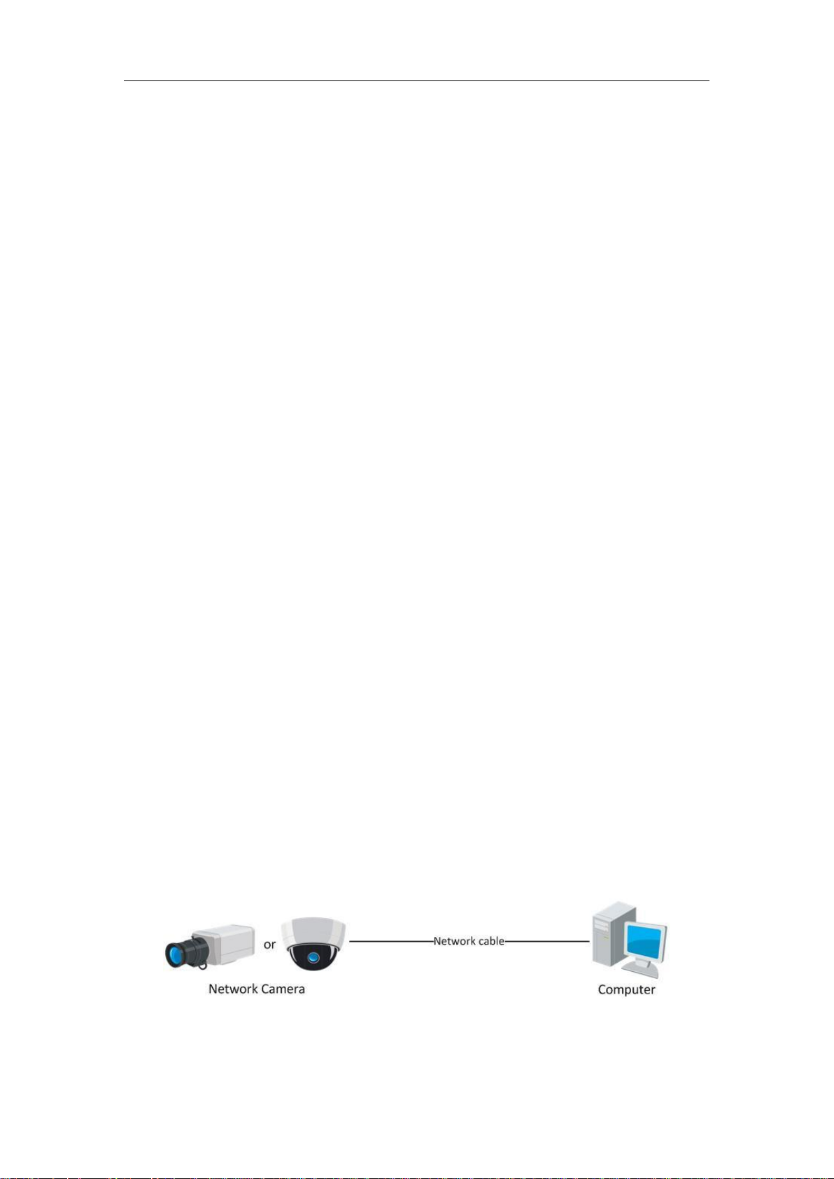
Purpose:
To test the network camera, you can directly connect the network camera to the
computer with a network cable as shown in Figure 2-1.
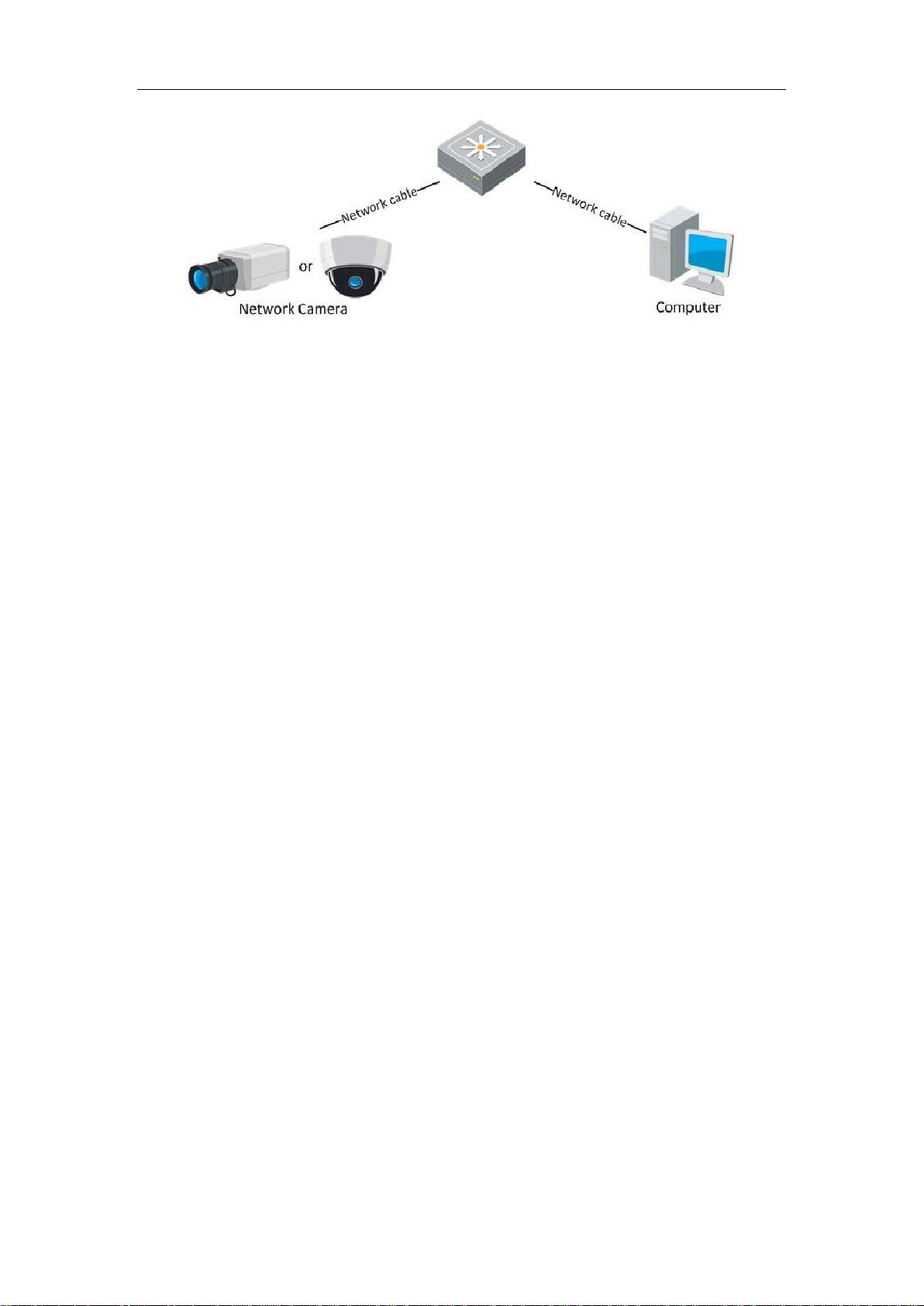
Refer to the Figure 2-2 to set network camera over the LAN via a switch or a
router.
Figure 2-1 Connecting Directly
10
Page 12
User Manual of Network Camera
Figure 2-2 Connecting via a Switch or a Router
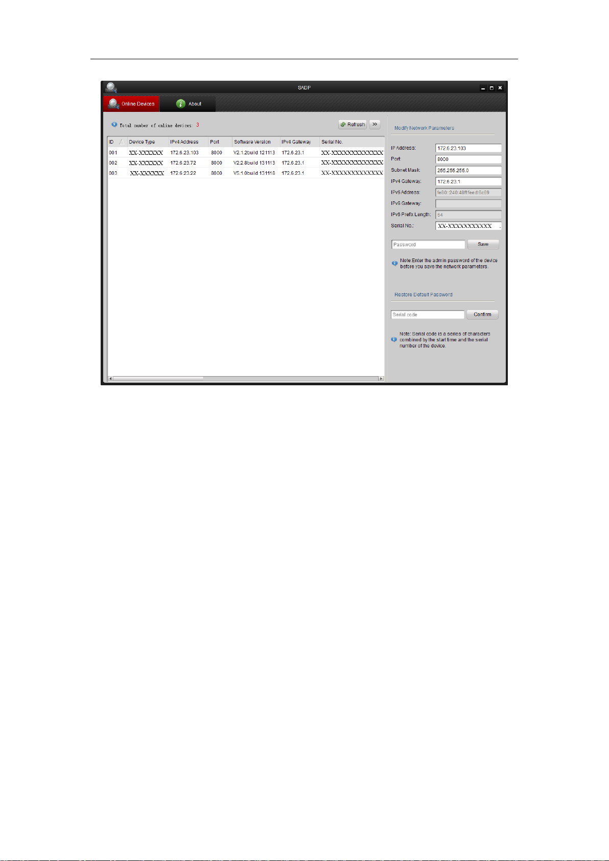
2.1.2 Detecting and Changing the IP Address
You need the IP address to visit the network camera.
Steps:
1. To get the IP address, you can choose either of the following methods:
Use SADP, a software tool which can automatically detect the online
network cameras in the LAN and list the device information including IP
address, subnet mask, port number, device serial number, device version, etc.,
shown in Figure 2-3.
Use the iVMS-4200 client software to list the online devices. Please refer to
the user manual of iVMS-4200 client software for detailed information.
2. Change the IP address and subnet mask to the same subnet as that of your
computer.
3. Enter the IP address of network camera in the address field of the web browser to
view the live video.
Notes:
The default IP address is 192.0.0.64 and the port number is 8000. The default user
name is admin, and password is 12345. And you are highly recommended change
the initial password after your first login.
For accessing the network camera from different subnets, please set the gateway
for the network camera after you logged in. For detailed information, please refer
to Section 6.3.1 Configuring TCP/IP Settings.
11
Page 13
User Manual of Network Camera
Figure 2-3 SADP Interface
2.2 Setting the Network Camera over the WAN
Purpose:
This section explains how to connect the network camera to the WAN with a static IP
or a dynamic IP.
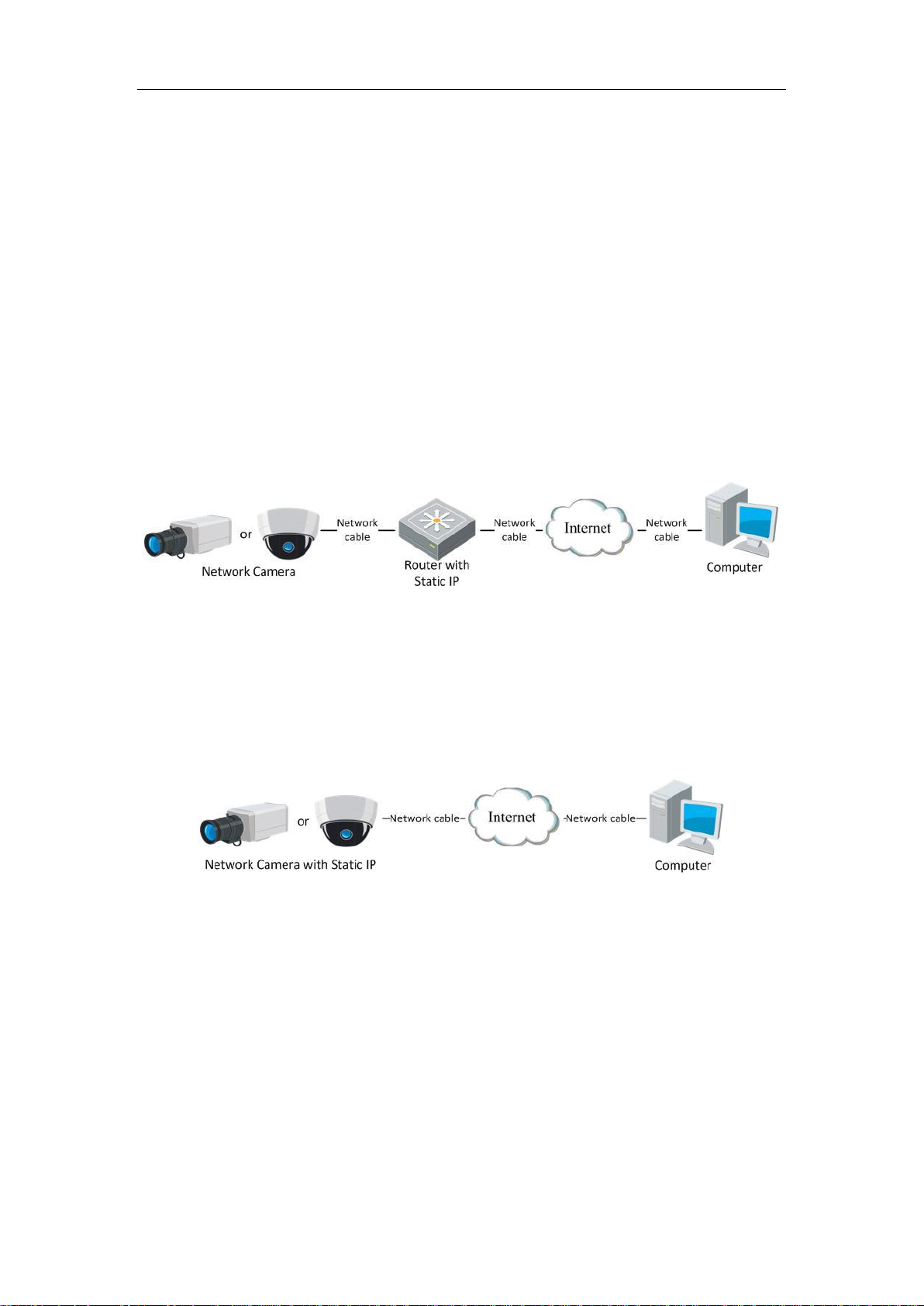
2.2.1 Static IP Connection
Before you start:
Please apply a static IP from an ISP (Internet Service Provider). With the static IP
address, you can connect the network camera via a router or connect it to the WAN
directly.
Connecting the network camera via a router
Steps:
1. Connect the network camera to the router.
12
Page 14
User Manual of Network Camera
2. Assign a LAN IP address, the subnet mask and the gateway. Refer to Section 2.1.2
Detecting and Changing the IP Address for detailed IP address configuration of
the camera.
3. Save the static IP in the router.
4. Set port mapping, e.g., 80, 8000, and 554 ports. The steps for port mapping vary
according to the different routers. Please call the router manufacturer for
assistance with port mapping.
Note: Refer to Appendix 2 for detailed information about port mapping.
5. Visit the network camera through a web browser or the client software over the
internet.
Figure 2-4 Accessing the Camera through Router with Static IP
Connecting the network camera with static IP directly
You can also save the static IP in the camera and directly connect it to the internet
without using a router. Refer to Section 2.1.2 Detecting and Changing the IP Address
for detailed IP address configuration of the camera.
Figure 2-5 Accessing the Camera with Static IP Directly
2.2.2 Dynamic IP Connection
Before you start:
Please apply a dynamic IP from an ISP. With the dynamic IP address, you can connect
the network camera to a modem or a router.
Connecting the network camera via a router
Steps:
13
Page 15
User Manual of Network Camera
1. Connect the network camera to the router.
2. In the camera, assign a LAN IP address, the subnet mask and the gateway. Refer
to Section 2.1.2 Detecting and Changing the IP Address for detailed LAN
configuration.
3. In the router, set the PPPoE user name, password and confirm the password.
4. Set port mapping. E.g. 80, 8000, and 554 ports. The steps for port mapping vary
depending on different routers. Please call the router manufacturer for assistance
with port mapping.
Note: Refer to Appendix 2 for detailed information about port mapping.
5. Apply a domain name from a domain name provider.
6. Configure the DDNS settings in the setting interface of the router.
7. Visit the camera via the applied domain name.
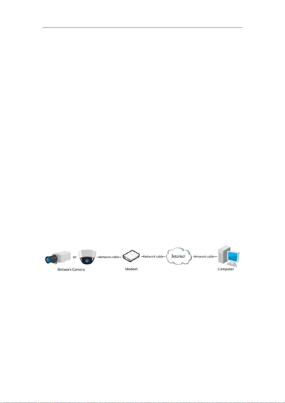
Connecting the network camera via a modem
Purpose:
This camera supports the PPPoE auto dial-up function. The camera gets a public IP
address by ADSL dial-up after the camera is connected to a modem. You need to
configure the PPPoE parameters of the network camera. Refer to Section 5.3.3
Configuring PPPoE Settings for detailed configuration.
Figure 2-6 Accessing the Camera with Dynamic IP
Note: The obtained IP address is dynamically assigned via PPPoE, so the IP address
always changes after rebooting the camera. To solve the inconvenience of the
dynamic IP, you need to get a domain name from the DDNS provider (E.g.
DynDns.com). Please follow the steps below for normal domain name resolution and
private domain name resolution to solve the problem.
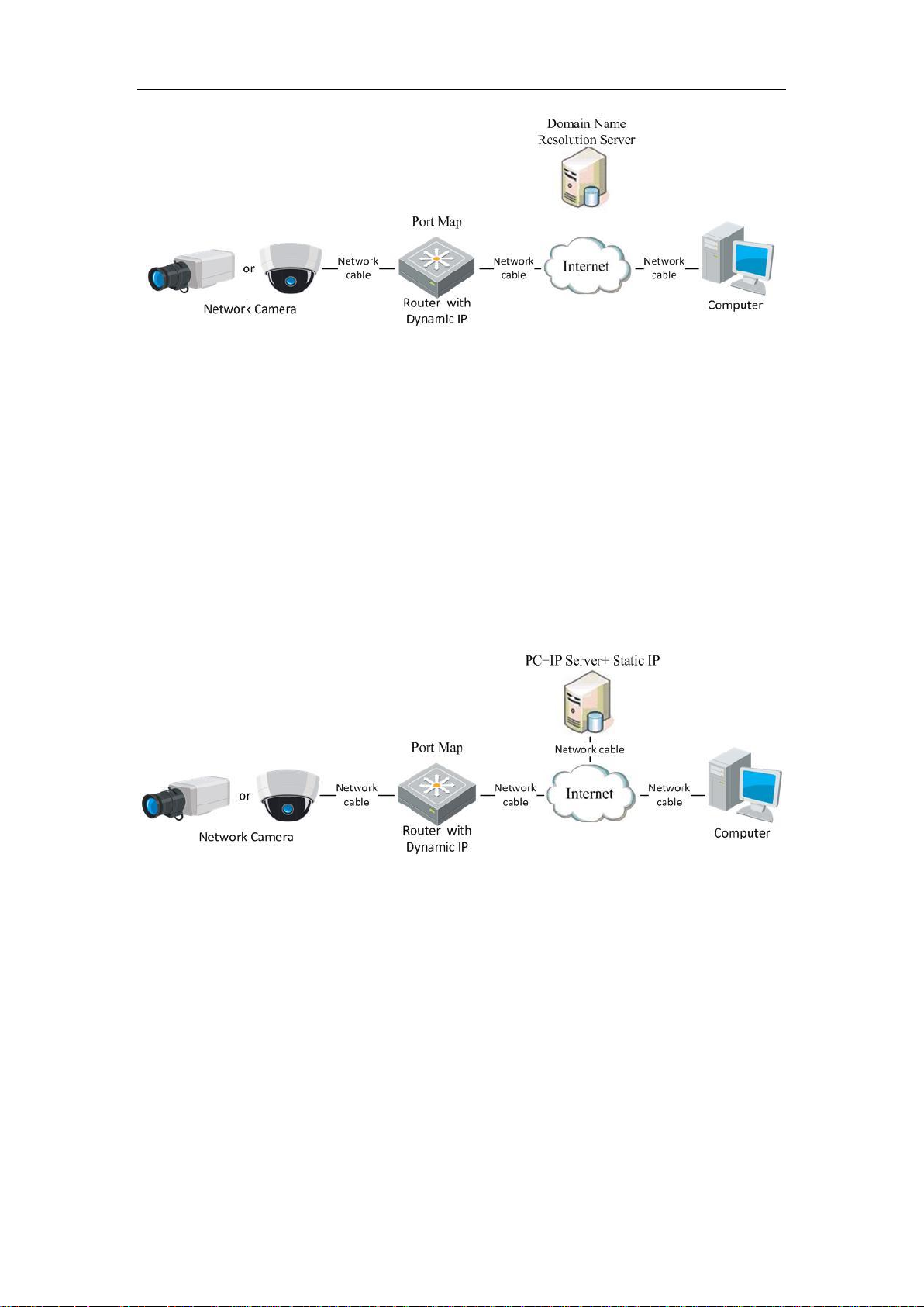
Normal Domain Name Resolution
14
Page 16
User Manual of Network Camera
Figure 2-7 Normal Domain Name Resolution
Steps:
1. Apply a domain name from a domain name provider.
2. Configure the DDNS settings in the DDNS Settings interface of the network
camera. Refer to Section 6.3.4 Configuring DDNS Settings for detailed
configuration.
3. Visit the camera via the applied domain name.
Private Domain Name Resolution
Figure 2-8 Private Domain Name Resolution
Steps:
1. Install and run the IP Server software in a computer with a static IP.
2. Access the network camera through the LAN with a web browser or the client
software.
3. Enable DDNS and select IP Server as the protocol type. Refer to Section 6.3.4
Configuring DDNS Settings for detailed configuration.
15
Page 17
User Manual of Network Camera
Chapter 3 Access to the Network
Camera
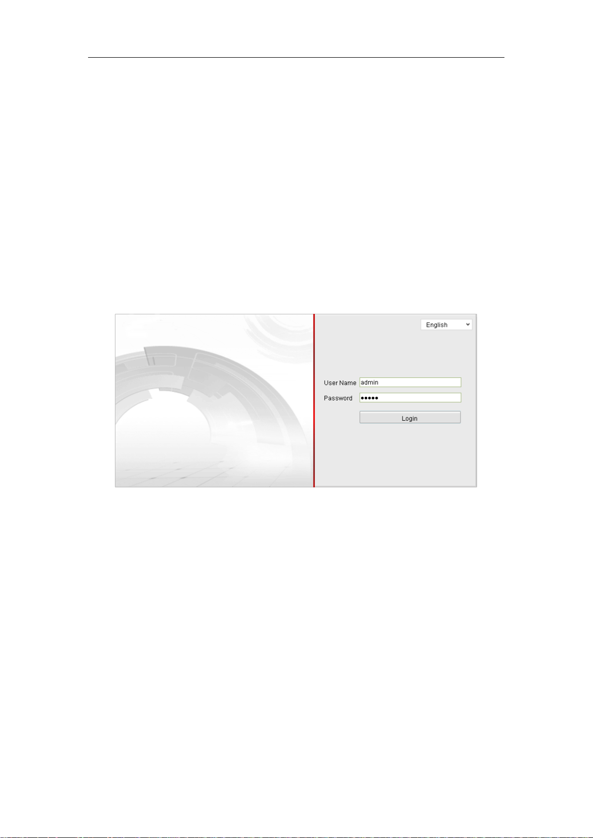
3.1 Accessing by Web Browsers
Steps:
1. Open the web browser.
2. Input the IP address of the network camera in the address bar, e.g., 192.0.0.64 and
press the Enter key to enter the login interface.
3. Input the user name and password and click Login.
Figure 3-1 Login Interface
Notes:
The default user name is admin, and the default password is 12345.
Multi-language is supported. English, Simplified Chinese, Traditional Chinese,
Russian, Turkish, Japanese, Korean, Thai, Vietnamese, Estonian, Bulgarian,
Hungarian, Czech, Slovak, French, Italian, German, Spanish, Portuguese, Polish,
Greek, Dutch, Romanian, Finnish, Norwegian, Danish, Swedish, Croatian,
Serbian, Slovenian, etc.
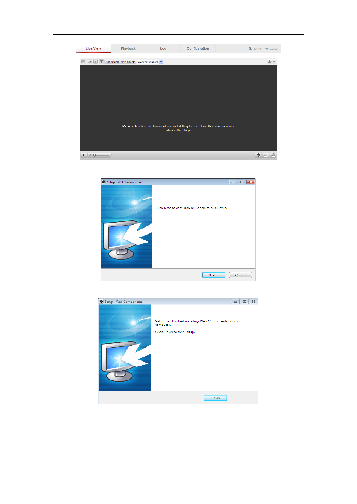
4. Install the plug-in before viewing the live video and operating the camera. Please
follow the installation prompts to install the plug-in.
16
Page 18
User Manual of Network Camera
Figure 3-2 Download and Install Plug-in
Figure 3-3 Install Plug-in (1)
Figure 3-4 Install Plug-in (2)
Note: You may have to close the web browser to install the plug-in. Please reopen the
web browser and log in again after installing the plug-in.
17
Page 19
User Manual of Network Camera
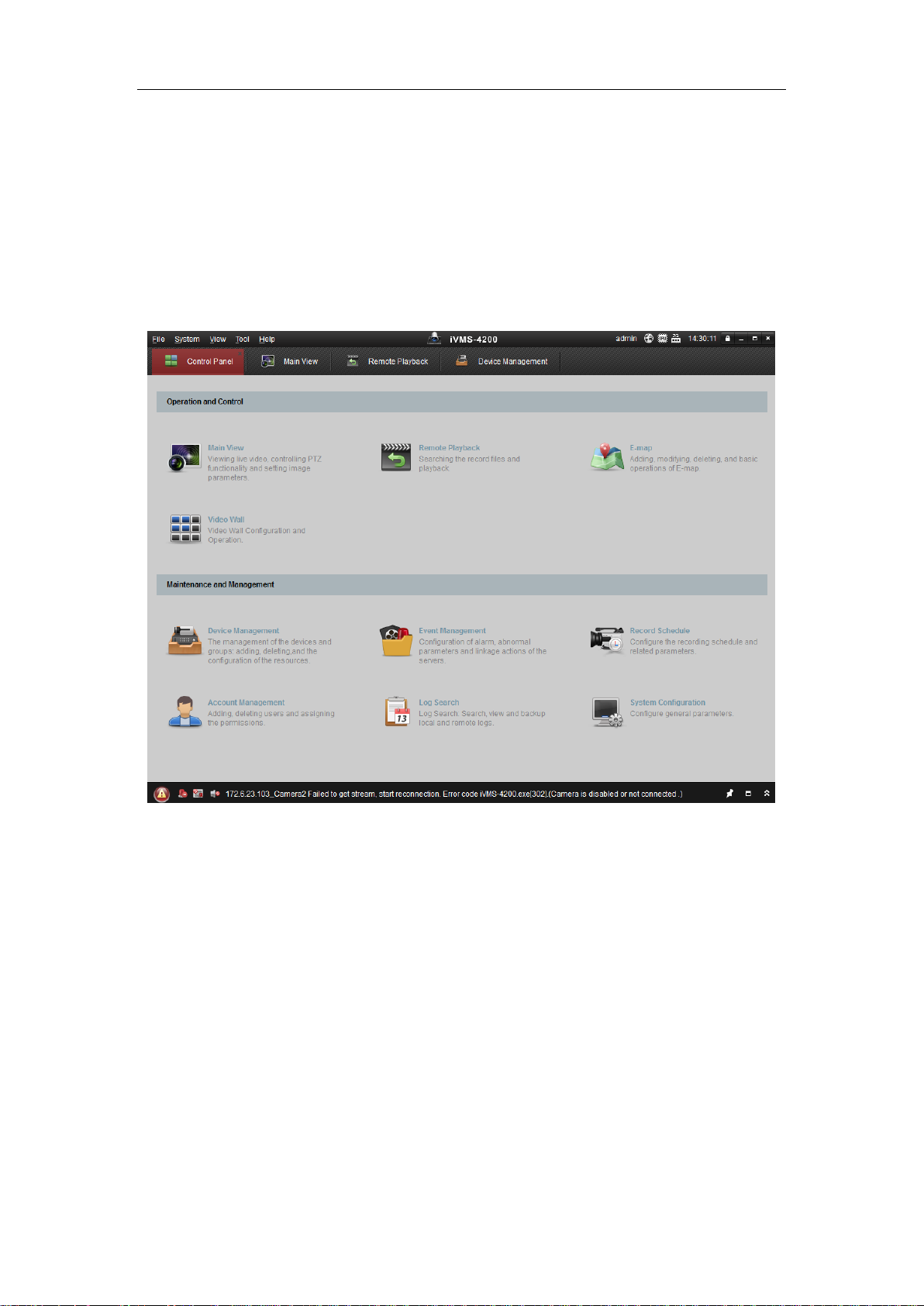
3.2 Accessing by Client Software
The product CD contains the iVMS-4200 client software. You can view the live video
and manage the camera with the software.
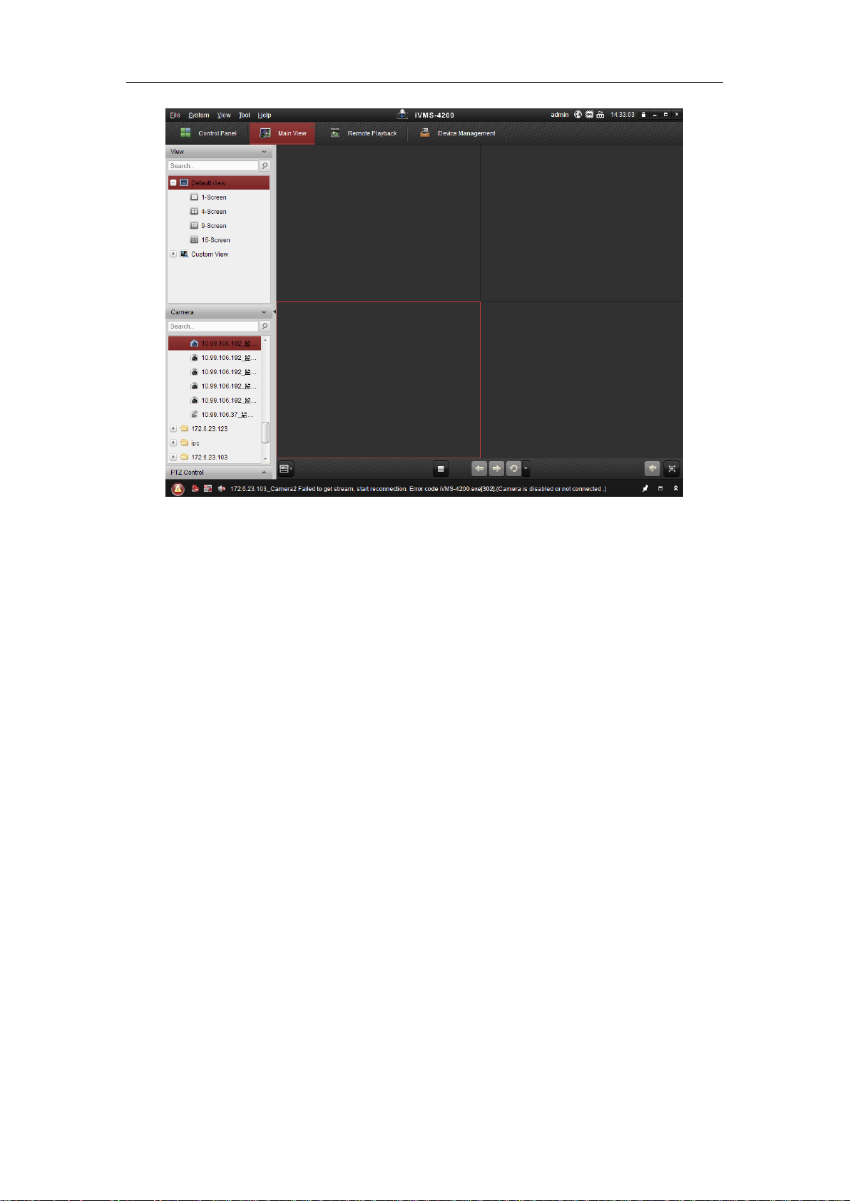
Follow the installation prompts to install the software. The control panel and live view
interface of iVMS-4200 client software are shown as bellow.
Figure 3-5 iVMS-4200 Control Panel
18
Page 20
User Manual of Network Camera
Figure 3-6 iVMS-4200 Configuration Panel
Note: For detailed information about the software, please refer to the user manual of
the iVMS-4200.
19
Page 21
User Manual of Network Camera
Chapter 4 Wi-Fi Settings
Purpose:
By connecting to the wireless network, you don’t need to use cable of any kind for
network connection, which is very convenient for the actual surveillance application.
Note: This chapter is only applicable for the cameras with the built-in Wi-Fi module.
4.1 Configuring Wi-Fi Connection in Manage and
Ad-hoc Modes
Before you start:
A wireless network must be configured.
Wireless Connection in Manage Mode
Steps:
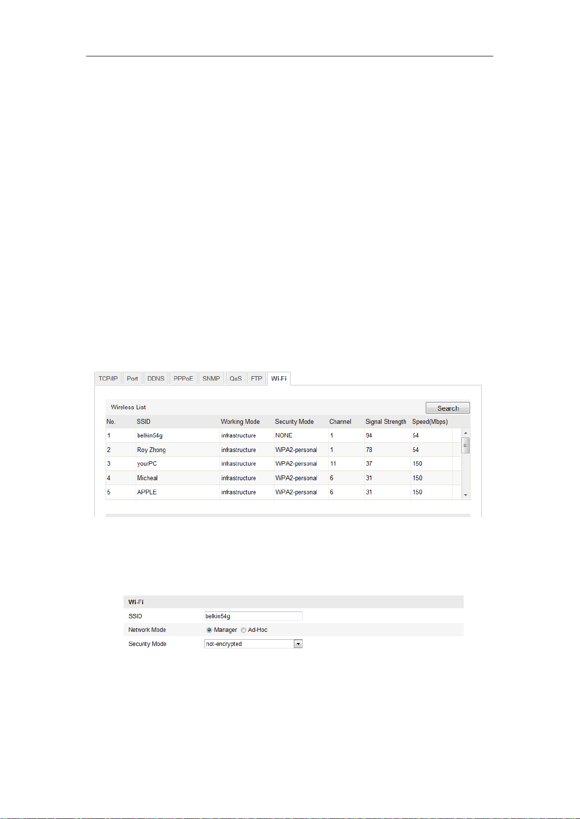
1. Enter the Wi-Fi configuration interface.
Configuration> Advanced Configuration> Network> Wi-Fi
Figure 4-1 Wireless Network List
2. Click Search to search the online wireless connections.
3. Click to choose a wireless connection on the list.
Figure 4-2 Wi-Fi Setting- Manage Mode
20
Page 22
User Manual of Network Camera
4. Check the checkbox to select the Network mode as Manage, and the Security
mode of the network is automatically shown when you select the wireless
network, please don’t change it manually.
Note: These parameters are exactly identical with those of the router.
5. Enter the key to connect the wireless network. The key should be that of the
wireless network connection you set on the router.
Wireless Connection in Ad-hoc Mode
If you choose the Ad-hoc mode, you don’t need to connect the wireless camera via a
router. The scenario is the same as you connect the camera and the PC directly with a
network cable.
Steps:
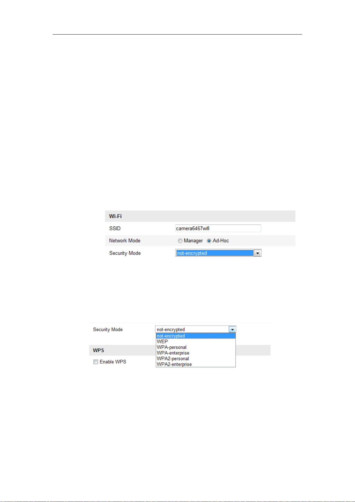
1. Choose Ad-hoc mode.
Figure 4-3 Wi-Fi Setting- Ad-hoc
2. Customize a SSID for the camera.
3. Choose the Security Mode of the wireless connection.
Figure 4-4 Security Mode- Ad-hoc Mode
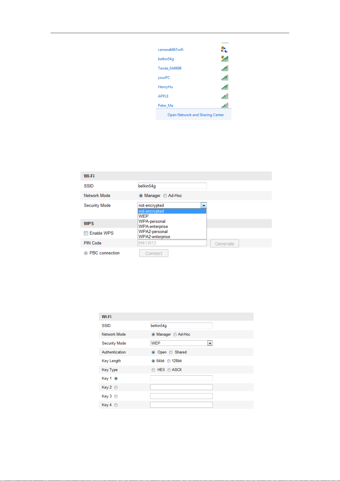
4. Enable the wireless connection function for your PC.
5. On the PC side, search the network and you can see the SSID of the camera
listed.
21
Page 23
User Manual of Network Camera
Figure 4-5 Ad-hoc Connection Point
6. Choose the SSID and connect.
Security Mode Description:
Figure 4-6 Security Mode
You can choose the Security Mode as not-encrypted, WEP, WPA-personal,
WPA-enterprise, WPA2-personal, and WPA2-enterprise.
WEP mode:
Figure 4-7 WEP Mode
Authentication - Select Open or Shared Key System Authentication, depending on
22
Page 24
User Manual of Network Camera
the method used by your access point. Not all access points have this option, in
which case they probably use Open System, which is sometimes known as SSID
Authentication.
Key length - This sets the length of the key used for the wireless encryption, 64 or
128 bit. The encryption key length can sometimes be shown as 40/64 and
104/128.
Key type - The key types available depend on the access point being used. The
following options are available:
HEX - Allows you to manually enter the hex key.
ASCII - In this method the string must be exactly 5 characters for 64-bit WEP
and 13 characters for 128-bit WEP.
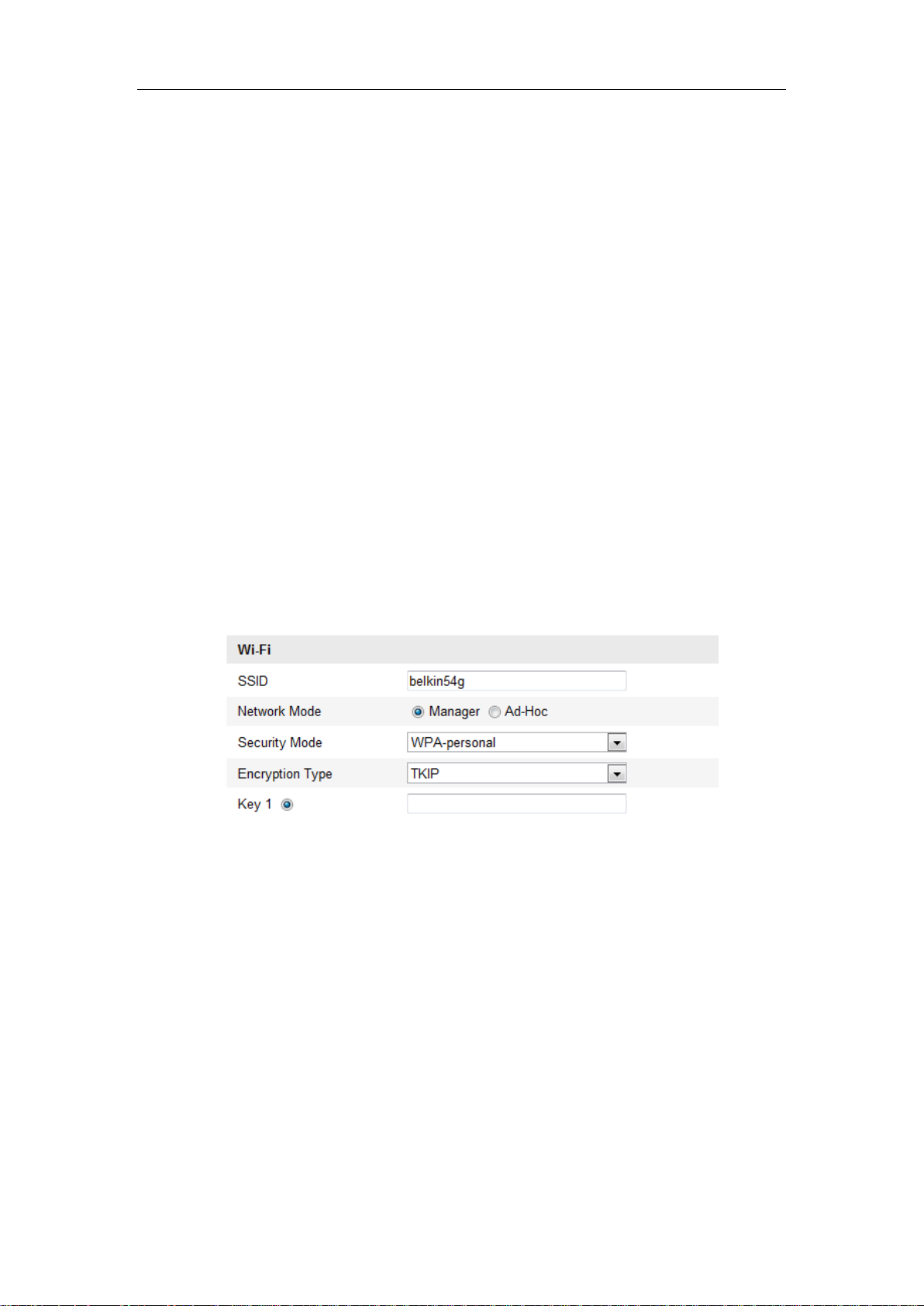
WPA-personal and WPA2-personal Mode:
Enter the required Pre-shared Key for the access point, which can be a hexadecimal
number or a passphrase.
Figure 4-8 Security Mode- WPA-personal
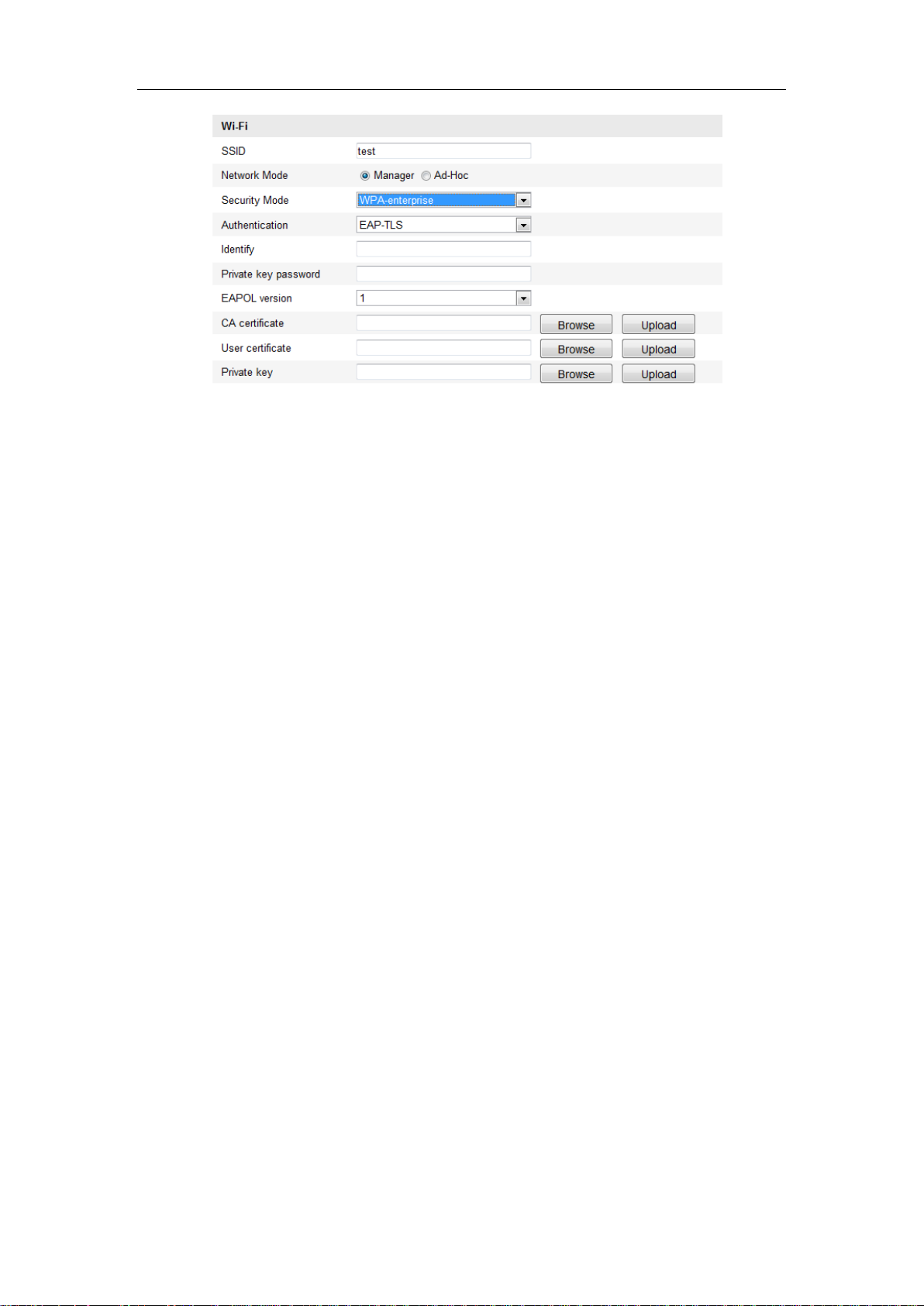
WPA- enterprise and WPA2-enterprise Mode:
Choose the type of client/server authentication being used by the access point;
EAP-TLS or EAP-PEAP.
EAP-TLS
23
Page 25
User Manual of Network Camera
Figure 4-9 EAP-TLS
Identity - Enter the user ID to present to the network.
Private key password – Enter the password for your user ID.
EAPOL version - Select the version used (1 or 2) in your access point.
CA Certificates - Upload a CA certificate to present to the access point for
authentication.
EAP-PEAP:
User Name - Enter the user name to present to the network
Password - Enter the password of the network
PEAP Version - Select the PEAP version used at the access point.
Label - Select the label used by the access point.
EAPOL version - Select version (1 or 2) depending on the version used at the
access point
CA Certificates - Upload a CA certificate to present to the access point for
authentication
4.2 Easy Wi-Fi Connection with WPS function
Purpose:
The setting of the wireless network connection is never easy. To avoid the complex
setting of the wireless connection you can enable the WPS function.
24
Page 26
User Manual of Network Camera
WPS (Wi-Fi Protected Setup) refers to the easy configuration of the encrypted
connection between the device and the wireless router. The WPS makes it easy to add
new devices to an existing network without entering long passphrases. There are two
modes of the WPS connection, the PBC mode and the PIN mode.
Note: If you enable the WPS function, you do not need to configure the parameters
such as the encryption type and you don’t need to know the key of the wireless
connection.
Steps:
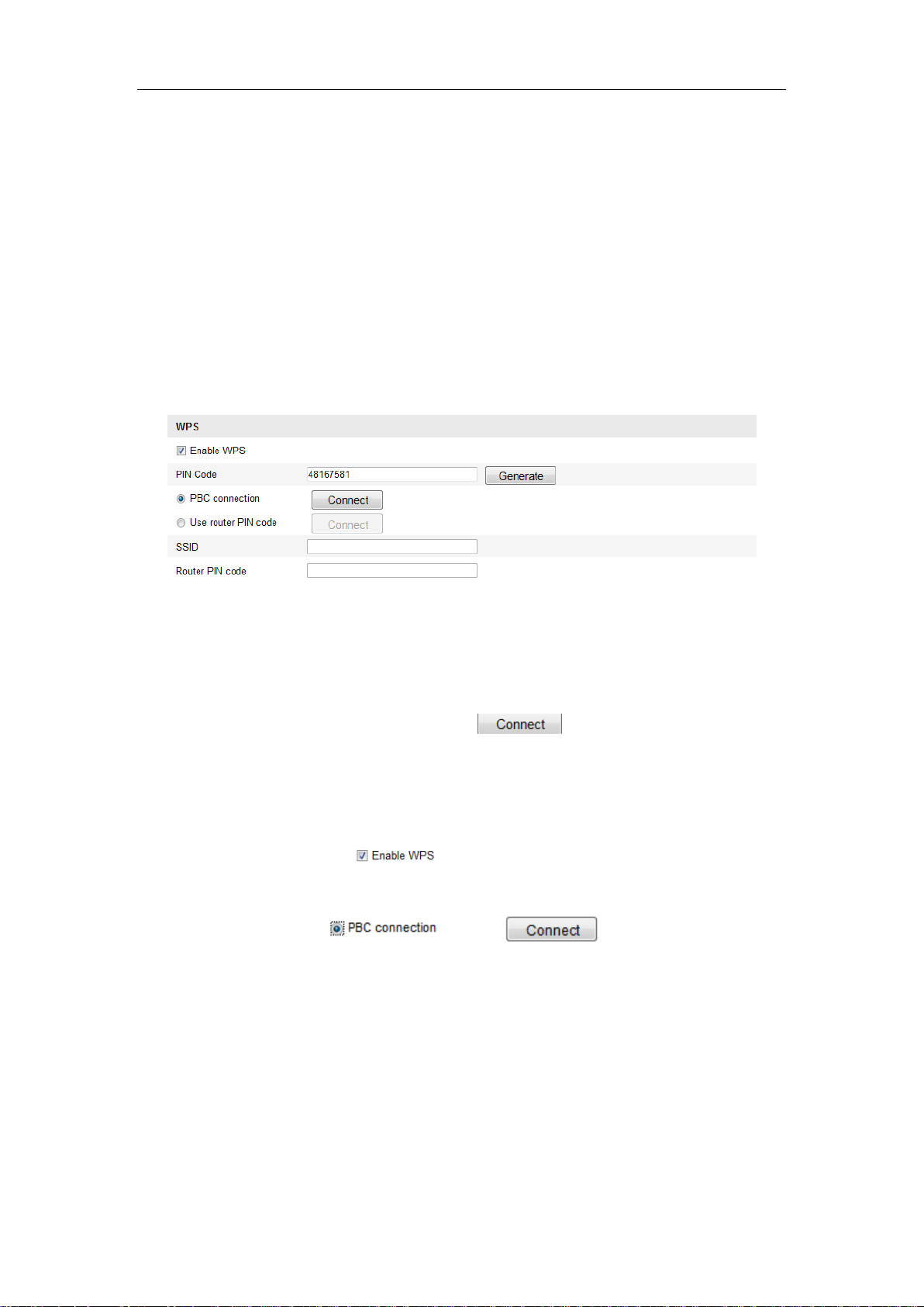
Figure 4-10 Wi-Fi Settings - WPS
PBC Mode:
PBC refers to the Push-Button-Configuration, in which the user simply has to push a
button, either an actual or virtual one (as the button on the configuration
interface of the IE browser), on both the Access Point (and a registrar of the network)
and the new wireless client device.
1. Check the checkbox of to enable WPS.
2. Choose the connection mode as PBC.
Note: Support of this mode is mandatory for both the Access Points and the
connecting devices.
3. Check on the Wi-Fi router to see if there is a WPS button. If yes push the button
and you can see the indicator near the button start flashing, which means the WPS
function of the router is enabled. For detailed operation, please see the user guide of
the router.
25
Page 27
User Manual of Network Camera
4. Push the WPS button to enable the function on the camera.
If there is not a WPS button on the camera, you can also click the virtual button to
enable the PBC function on the web interface.
5. Click Connect button.
When the PBC mode is both enabled in the router and the camera, the camera and the
wireless network is connected automatically.
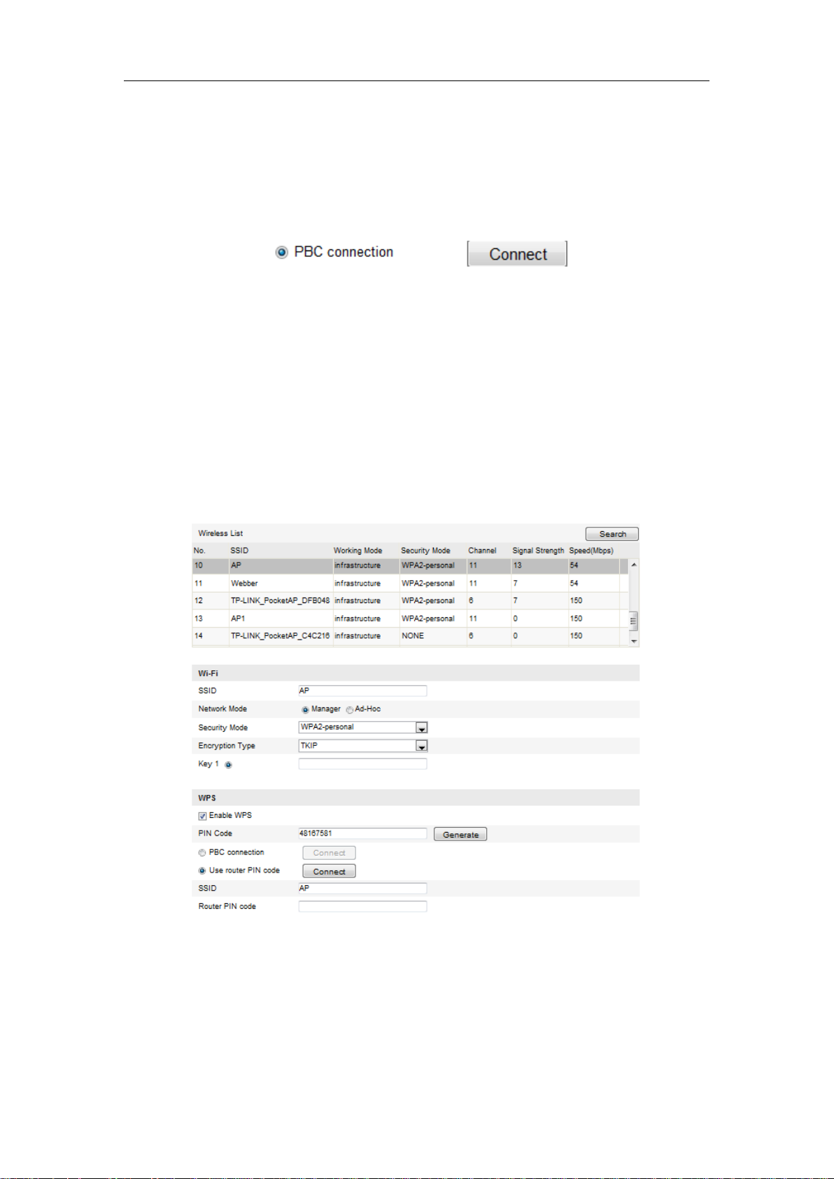
PIN Mode:
The PIN mode requires a Personal Identification Number (PIN) to be read from either
a sticker or the display on the new wireless device. This PIN must then be entered to
connect the network, usually the Access Point of the network.
Steps:
1. Choose a wireless connection on the list and the SSID is shown.
Figure 4-11 Wi-Fi Settings – WPS PIN Mode
2. Choose Use route PIN code.
If the PIN code is generated from the router side, you should enter the PIN code you
get from the router side in the Router PIN code field.
26
Page 28
User Manual of Network Camera
3. Click Connect.
Or
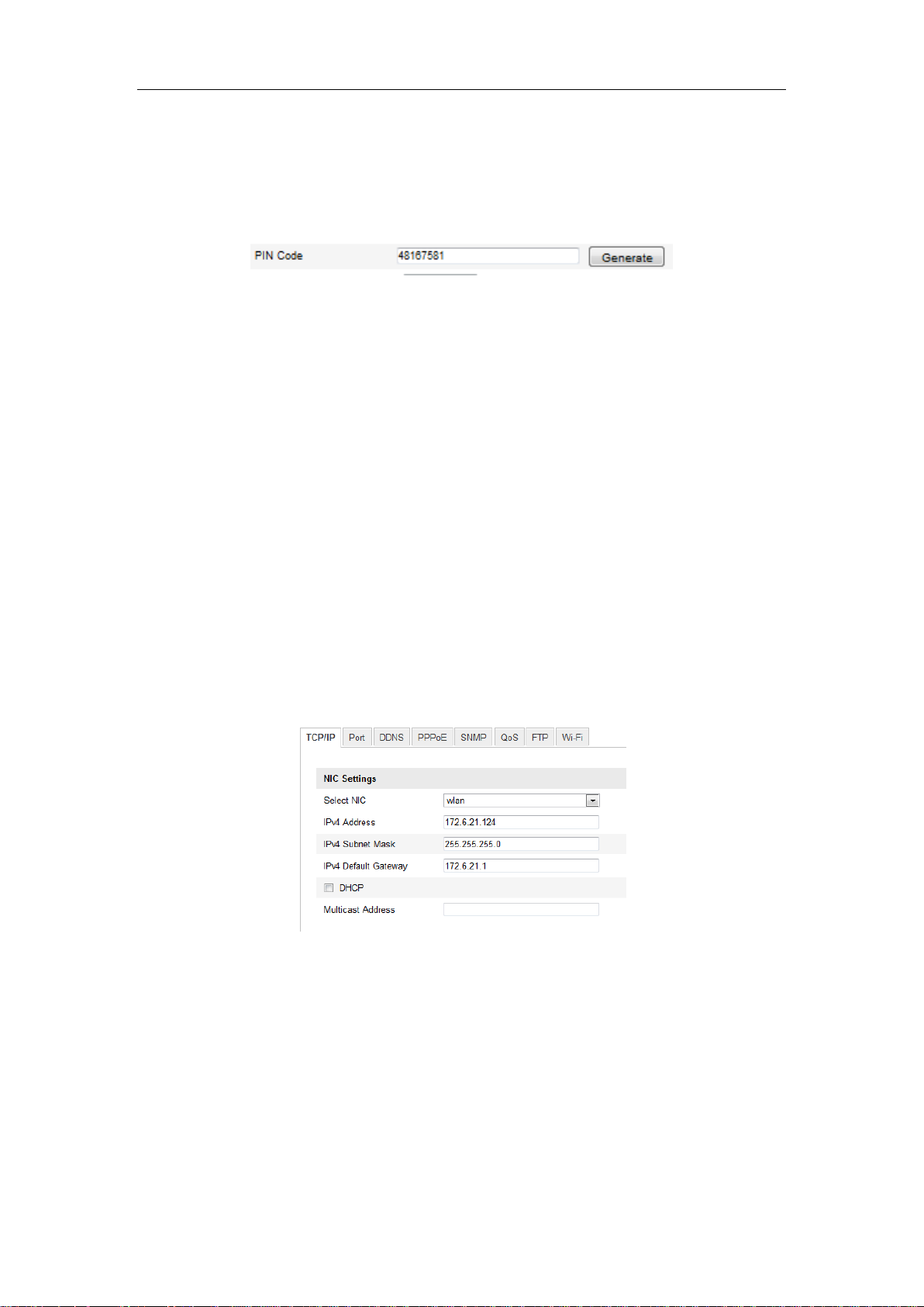
You can generate the PIN code on the camera side. And the expired time for the PIN
code is 120 seconds.
1. Click Generate.
2. Enter the code to the router, in the example, enter 48167581 to the router.
4.3 IP Property Settings for Wireless Network
Connection
The default IP address of wireless network interface controller is 192.168.1.64. When
you connect the wireless network you can change the default IP.
Steps:
1. Enter the TCP/IP configuration interface.
Configuration> Advanced Configuration> Network> TCP/IP
Or
Configuration> Basic Configuration> Network> TCP/IP
Figure 4-12 TCP/IP Settings
2. Select the NIC as wlan.
3. Customize the IPv4 address, the IPv4 Subnet Mask and the Default Gateway.
The setting procedure is the same with that of LAN.
If you want to be assigned the IP address you can check the checkbox to enable the
DHCP.
27
Page 29
User Manual of Network Camera
Chapter 5 Live View
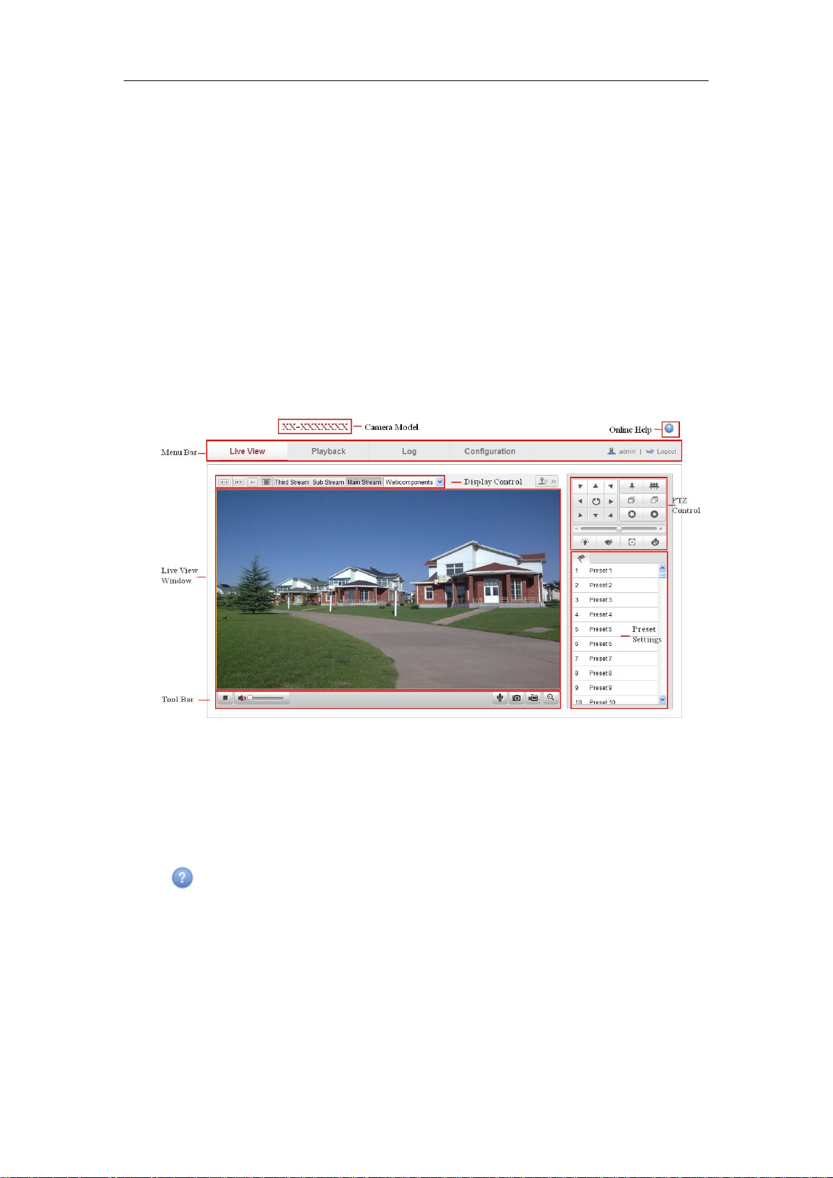
5.1 Live View Page
Purpose:
The live view page allows you to view the real-time video, capture images, realize
PTZ control, set/call presets and configure video parameters.
Log in the network camera to enter the live view page, or you can click Live View on
the menu bar of the main page to enter the live view page.
Descriptions of the live view page:
Figure 5-1 Live View Page
Camera Model:
It lists the camera model you are connecting to.
Online Help:
Click to get the online help, which will guide you through the basic operations for
each function.
Menu Bar:
Click each tab to enter Live View, Playback, Log and Configuration page
respectively.
Display Control:
28
Page 30
User Manual of Network Camera
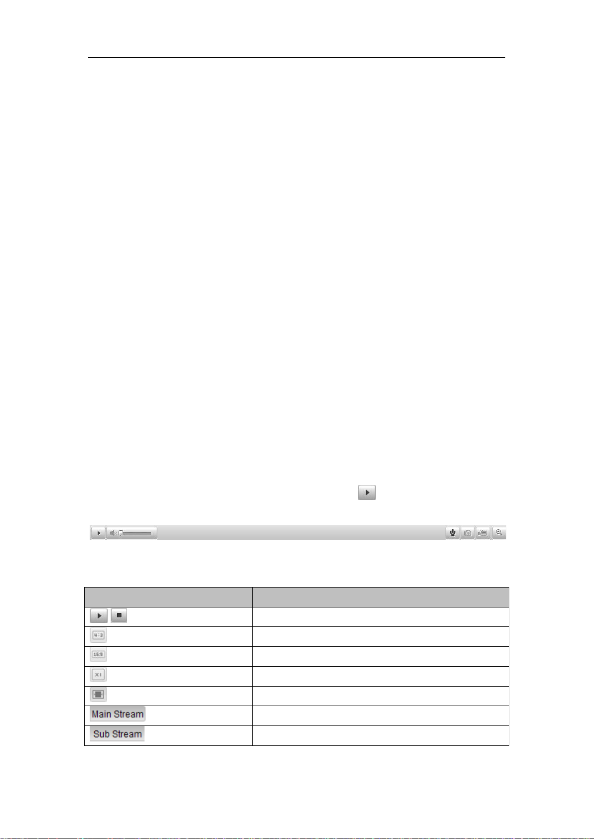
Icon
Description
/
Start/Stop live view.
The window size is 4:3.
The window size is 16:9.
The original widow size.
Self-adaptive window size.
Live view with the main stream.
Live view with the sub stream.
Click each tab to adjust the layout and the stream type of the live view. And you can
click the drop-down to select the plug-in. For IE (internet explorer) user,
webcomponents and quick time are selectable. And for Non-IE user, webcomponents,
quick time, VLC or MJPEG is selectable if they are supported by the web browser.
Live View Window:
Display the live video.
Toolbar:
Operations on the live view page, e.g., live view, capture, record, audio on/off,
two-way audio, etc.
PTZ Control:
Panning, tilting and zooming actions of the camera and the lighter and wiper control
(if it supports PTZ function or an external pan/tilt unit has been installed).
Preset Setting/Calling:
Set and call the preset for the camera (if supports PTZ function or an external pan/tilt
unit has been installed).
5.2 Starting Live View
In the live view window as shown in Figure 5-2, click on the toolbar to start the
live view of the camera.
Figure 5-2 Live View Toolbar
Table 5-1 Descriptions of the Toolbar
29
Page 31

User Manual of Network Camera
Live view with the third stream.
Click to select the third-party plug-in.
Manually capture the picture.
/
Manually start/stop recording.
/
Audio on and adjust volume /Mute.
/
Turn on/off microphone.
/
Turn on/off 3D zooming function.
5.3 Recording and Capturing Pictures Manually
In the live view interface, click on the toolbar to capture the live pictures or
click to record the live view. The saving paths of the captured pictures and clips
can be set on the Configuration > Local Configuration page. To configure remote
scheduled recording, please refer to Section 7.2.
Note: The captured image will be saved as JPEG file or BMP file in your computer.
5.4 Operating PTZ Control
Purpose:
In the live view interface, you can use the PTZ control buttons to realize pan/tilt/zoom
control of the camera.
Before you start:
To realize PTZ control, the camera connected to the network must support the PTZ
function or a pan/tilt unit has been installed to the camera. Please properly set the PTZ
parameters on RS-485 settings page referring to Section 10.8 RS-485 Settings.
5.4.1 PTZ Control Panel
On the live view page, click to show the PTZ control panel or click to
hide it.
Click the direction buttons to control the pan/tilt movements.
30
Page 32

User Manual of Network Camera
Icon
Description
Zoom in/out
Focus near/far
Iris +/-
Light on/off
Wiper on/off
One-touch focus
Initialize lens
Adjust speed of pan/tilt movements
Figure 5-3 PTZ Control Panel
Click the zoom/iris/focus buttons to realize lens control.
Notes:
There are 8 direction arrows ( , , , , , , , ) in the live view window
when you click and drag the mouse in the relative positions.
For the cameras which support lens movements only, the direction buttons are
invalid.
Table 5-2 Descriptions of PTZ Control Panel
5.4.2 Setting / Calling a Preset
Setting a Preset:
1. In the PTZ control panel, select a preset number from the preset list.
Figure 5-4 Setting a Preset
31
Page 33

User Manual of Network Camera
2. Use the PTZ control buttons to move the lens to the desired position.
• Pan the camera to the right or left.
• Tilt the camera up or down.
• Zoom in or out.
• Refocus the lens.
3. Click to finish the setting of the current preset.
4. You can click to delete the preset.
Note: You can configure up to 128 presets.
Calling a Preset:
This feature enables the camera to point to a specified preset scene manually or when
an event takes place.
For the defined preset, you can call it at any time to the desired preset scene.
In the PTZ control panel, select a defined preset from the list and click to call the
preset.
Or you can place the mouse on the presets interface, and call the preset by typing the
preset No. to call the corresponding presets.
Figure 5-5 Calling a Preset
5.4.3 Setting / Calling a Patrol
Note:
No less than 2 presets have to be configured before you set a patrol.
Steps:
32
Page 34

User Manual of Network Camera
1. Click to enter the patrol configuration interface.
2. Select a path No., and click to add the configured presets.
3. Select the preset, and input the patrol duration and patrol speed.
4. Click OK to save the first preset.
5. Follow the steps above to add the other presets.
Figure 5-6 Add Patrol Path
6. Click to save a patrol.
7. Click to start the patrol, and click to stop it.
8. (Optional) Click to delete a patrol.
33
Page 35

User Manual of Network Camera
Chapter 6 Network Camera
Configuration
6.1 Configuring Local Parameters
Note: The local configuration refers to the parameters of the live view, record files
and captured pictures. The record files and captured pictures are the ones you record
and captured using the web browser and thus the saving paths of them are on the PC
running the browser.
Steps:
1. Enter the Local Configuration interface:
Configuration > Local Configuration
Figure 6-1 Local Configuration Interface
2. Configure the following settings:
Live View Parameters: Set the protocol type and live view performance.
Protocol Type: TCP, UDP, MULTICAST and HTTP are selectable.
TCP: Ensures complete delivery of streaming data and better video quality,
yet the real-time transmission will be affected.
UDP: Provides real-time audio and video streams.
HTTP: Allows the same quality as of TCP without setting specific ports for
34
Page 36

User Manual of Network Camera
streaming under some network environments.
MULTICAST: It’s recommended to select MCAST type when using the
Multicast function. For detailed information about Multicast, refer to Section
6.3.1 TCP/IP Settings.
Live View Performance: Set the live view performance to Shortest Delay,
Real Time, Balanced or Best Fluency.
Rules: It refers to the rules on your local browser, select enable or disable to
display or not display the colored marks when the motion detection, face
detection, or intrusion detection is triggered. E.g.: enabled as the rules are, and
the face detection is enabled as well, when a face is detected, it will be marked
with a green rectangle on the live view.
Image Format: Choose the image format for picture capture.
Record File Settings: Set the saving path of the recorded video files. Valid for the
record files you recorded with the web browser.
Record File Size: Select the packed size of the manually recorded and
downloaded video files to 256M, 512M or 1G. After the selection, the
maximum record file size is the value you selected.
Save record files to: Set the saving path for the manually recorded video files.
Save downloaded files to: Set the saving path for the downloaded video files
in playback mode.
Picture and Clip Settings: Set the saving paths of the captured pictures and
clipped video files. Valid for the pictures you captured with the web browser.
Save snapshots in live view to: Set the saving path of the manually captured
pictures in live view mode.
Save snapshots when playback to: Set the saving path of the captured
pictures in playback mode.
Save clips to: Set the saving path of the clipped video files in playback mode.
Note: You can click Browse to change the directory for saving the clips and pictures.
3. Click Save to save the settings.
35
Page 37

User Manual of Network Camera
6.2 Configuring Time Settings
Purpose:
You can follow the instructions in this section to configure the time synchronization
and DST settings.
Steps:
1. Enter the Time Settings interface:
Configuration > Basic Configuration > System > Time Settings
Or Configuration > Advanced Configuration > System > Time Settings
Figure 6-2 Time Settings
Select the Time Zone.
Select the Time Zone of your location from the drop-down menu.
Synchronizing Time by NTP Server.
(1) Check the checkbox to enable the NTP function.
(2) Configure the following settings:
Server Address: IP address of NTP server.
NTP Port: Port of NTP server.
Interval: The time interval between the two synchronizing actions with NTP
server.
36
Page 38

User Manual of Network Camera
Figure 6-3 Time Sync by NTP Server
Note: If the camera is connected to a public network, you should use a NTP server
that has a time synchronization function, such as the server at the National Time
Center (IP Address: 210.72.145.44). If the camera is set in a customized network,
NTP software can be used to establish a NTP server for time synchronization.
Synchronizing Time Synchronization Manually
Enable the Manual Time Sync function and then click to set the system time
from the pop-up calendar.
Note: You can also check the Sync with computer time checkbox to synchronize the
time of the camera with that of your computer.
Figure 6-4 Time Sync Manually
Click the DST tab page to enable the DST function and Set the date of the DST
period.
Figure 6-5 DST Settings
2. Click Save to save the settings.
37
Page 39

User Manual of Network Camera
6.3 Configuring Network Settings
6.3.1 Configuring TCP/IP Settings
Purpose:
TCP/IP settings must be properly configured before you operate the camera over
network. The camera supports both the IPv4 and IPv6. Both versions may be
configured simultaneously without conflicting to each other, and at least one IP
version should be configured.
Steps:
1. Enter TCP/IP Settings interface:
Configuration > Basic Configuration > Network > TCP/IP
Or Configuration > Advanced Configuration > Network > TCP/IP
Figure 6-6 TCP/IP Settings
2. Configure the basic network settings, including the NIC Type, IPv4 or IPv6
Address, IPv4 or IPv6 Subnet Mask, IPv4 or IPv6 Default Gateway, MTU settings
38
Page 40

User Manual of Network Camera
and Multicast Address.
Notes:
The valid value range of MTU is 500 ~ 1500.
The Multicast sends a stream to the multicast group address and allows multiple
clients to acquire the stream at the same time by requesting a copy from the
multicast group address. Before utilizing this function, you have to enable the
Multicast function of your router.
3. Click Save to save the above settings.
Note: A reboot is required for the settings to take effect.
6.3.2 Configuring Port Settings
Purpose:
You can set the port No. of the camera, e.g. HTTP port, RTSP port and HTTPS port.
Steps:
1. Enter the Port Settings interface:
Configuration > Basic Configuration > Network > Port
Or Configuration > Advanced Configuration > Network > Port
Figure 6-7 Port Settings
2. Set the HTTP port, RTSP port, HTTPS port and server port of the camera.
HTTP Port: The default port number is 80, and it can be changed to any port No.
which is not occupied.
RTSP Port: The default port number is 554 and it can be changed to any port No.
ranges from 1024 to 65535.
39
Page 41

User Manual of Network Camera
HTTPS Port: The default port number is 443, and it can be changed to any port
No. which is not occupied.
Server Port: The default server port number is 8000, and it can be changed to
any port No. ranges from 2000 to 65535.
3. Click Save to save the settings.
Note: A reboot is required for the settings to take effect.
6.3.3 Configuring PPPoE Settings
Steps:
1. Enter the PPPoE Settings interface:
Configuration >Advanced Configuration > Network > PPPoE
Figure 6-8 PPPoE Settings
2. Check the Enable PPPoE checkbox to enable this feature.
3. Enter User Name, Password, and Confirm password for PPPoE access.
Note: The User Name and Password should be assigned by your ISP.
4. Click Save to save and exit the interface.
Note: A reboot is required for the settings to take effect.
6.3.4 Configuring DDNS Settings
Purpose:
If your camera is set to use PPPoE as its default network connection, you can use the
Dynamic DNS (DDNS) for network access.
Before you start:
40
Page 42

User Manual of Network Camera
Registration on the DDNS server is required before configuring the DDNS settings of
the camera.
Steps:
1. Enter the DDNS Settings interface:
Configuration > Advanced Configuration > Network > DDNS
Figure 6-9 DDNS Settings
2. Check the Enable DDNS checkbox to enable this feature.
3. Select DDNS Type. Four DDNS types are selectable: HiDDNS, IPServer, NO-IP,
and DynDNS.
DynDNS:
Steps:
(1) Enter Server Address of DynDNS (e.g. members.dyndns.org).
(2) In the Domain text field, enter the domain name obtained from the DynDNS
website.
(3) Enter the Port of DynDNS server.
(4) Enter the User Name and Password registered on the DynDNS website.
(5) Click Save to save the settings.
41
Page 43

User Manual of Network Camera
Figure 6-10 DynDNS Settings
IP Server:
Steps:
(1) Enter the Server Address of the IP Server.
(2) Click Save to save the settings.
Note: For the IP Server, you have to apply a static IP, subnet mask, gateway and
preferred DNS from the ISP. The Server Address should be entered with the
static IP address of the computer that runs the IP Server software.
Figure 6-11 IPServer Settings
Note: For the US and Canada area, you can enter 173.200.91.74 as the server
address.
NO-IP:
Steps:
(1) Choose the DDNS Type as NO-IP.
42
Page 44

User Manual of Network Camera
Figure 6-12 NO-IP Settings
(2) Enter the Server Address as www.noip.com
(3) Enter the Domain name you registered.
(4) Enter the Port number, if needed.
(5) Enter the User Name and Password.
(6) Click Save and then you can view the camera with the domain name.
HiDDNS
Steps:
(1) Choose the DDNS Type as HiDDNS.
Figure 6-13 HiDDNS Settings
(2) Enter the Server Address www.hik-online.com.
(3) Enter the Domain name of the camera. The domain is the same with the
device alias in the HiDDNS server.
(4) Click Save to save the new settings.
Note: A reboot is required for the settings to take effect.
43
Page 45

User Manual of Network Camera
6.3.5 Configuring SNMP Settings
Purpose:
You can set the SNMP function to get camera status, parameters and alarm related
information and manage the camera remotely when it is connected to the network.
Before you start:
Before setting the SNMP, please download the SNMP software and manage to
receive the camera information via SNMP port. By setting the Trap Address, the
camera can send the alarm event and exception messages to the surveillance center.
Note: The SNMP version you select should be the same as that of the SNMP software.
And you also need to use the different version according to the security level you
required. SNMP v1 provides no security and SNMP v2 requires password for access.
And SNMP v3 provides encryption and if you use the third version, HTTPS protocol
must be enabled.
Steps:
1. Enter the SNMP Settings interface:
Configuration > Advanced Configuration > Network > SNMP
44
Page 46

User Manual of Network Camera
Figure 6-14 SNMP Settings
2. Check the corresponding version checkbox ( ,
, ) to enable the feature.
3. Configure the SNMP settings.
Note: The settings of the SNMP software should be the same as the settings you
configure here.
4. Click Save to save and finish the settings.
Note: A reboot is required for the settings to take effect.
45
Page 47

User Manual of Network Camera
6.3.6 Configuring 802.1X Settings
Purpose:
The IEEE 802.1X standard is supported by the network cameras, and when the feature
is enabled, the camera data is secured and user authentication is needed when
connecting the camera to the network protected by the IEEE 802.1X.
Before you start:
The authentication server must be configured. Please apply and register a user name
and password for 802.1X in the server.
Steps:
1. Enter the 802.1X Settings interface:
Configuration > Advanced Configuration > Network > 802.1X
Figure 6-15 802.1X Settings
2. Check the Enable IEEE 802.1X checkbox to enable the feature.
3. Configure the 802.1X settings, including EAPOL version, user name and
password.
Note: The EAPOL version must be identical with that of the router or the switch.
4. Enter the user name and password to access the server.
5. Click Save to finish the settings.
Note: A reboot is required for the settings to take effect.
46
Page 48

User Manual of Network Camera
6.3.7 Configuring QoS Settings
Purpose:
QoS (Quality of Service) can help solve the network delay and network congestion by
configuring the priority of data sending.
Steps:
1. Enter the QoS Settings interface:
Configuration >Advanced Configuration > Network > QoS
Figure 6-16 QoS Settings
2. Configure the QoS settings, including video / audio DSCP, event / alarm DSCP
and Management DSCP.
The valid value range of the DSCP is 0-63. The bigger the DSCP value is, the
higher the priority is.
Note: DSCP refers to the Differentiated Service Code Point; and the DSCP value
is used in the IP header to indicate the priority of the data.
3. Click Save to save the settings.
Note: A reboot is required for the settings to take effect.
6.3.8 Configuring UPnP™ Settings
Universal Plug and Play (UPnP™) is a networking architecture that provides
compatibility among networking equipment, software and other hardware devices.
The UPnP protocol allows devices to connect seamlessly and to simplify the
implementation of networks in the home and corporate environments.
With the function enabled, you don’t need to configure the port mapping for each port,
47
Page 49

User Manual of Network Camera
and the camera is connected to the Wide Area Network via the router.
Steps:
1. Enter the UPnP™ settings interface.
Configuration >Advanced Configuration > Network > UPnP
2. Check the checkbox to enable the UPnP™ function.
The name of the device when detected online can be edited.
Figure 6-17 Configure UPnP Settings
6.3.9 Email Sending Triggered by Alarm
Purpose:
The system can be configured to send an Email notification to all designated receivers
if an alarm event is detected, e.g., motion detection event, video loss, video tampering,
etc.
Before you start:
Please configure the DNS Server settings under Basic Configuration > Network >
TCP/IP or Advanced Configuration > Network > TCP/IP before using the Email
function.
Steps:
1. Enter the TCP/IP Settings (Configuration > Basic Configuration > Network >
TCP/IP or Configuration > Advanced Configuration > Network > TCP/IP) to
set the IPv4 Address, IPv4 Subnet Mask, IPv4 Default Gateway and the Preferred
DNS Server.
Note: Please refer to Section 6.3.1 Configuring TCP/IP Settings for detailed
information.
2. Enter the Email Settings interface:
Configuration > Advanced Configuration > Network > Email
48
Page 50

User Manual of Network Camera
Figure 6-18 Email Settings
3. Configure the following settings:
Sender: The name of the email sender.
Sender’s Address: The email address of the sender.
SMTP Server: The SMTP Server IP address or host name (e.g.,
smtp.263xmail.com).
SMTP Port: The SMTP port. The default TCP/IP port for SMTP is 25 (not
secured). And the SSL SMTP port is 465.
Enable SSL: Check the checkbox to enable SSL if it is required by the SMTP
server.
Attached Image: Check the checkbox of Attached Image if you want to send
emails with attached alarm images.
Interval: The interval refers to the time between two actions of sending attached
pictures.
49
Page 51

User Manual of Network Camera
Authentication (optional): If your email server requires authentication, check
this checkbox to use authentication to log in to this server and enter the login user
Name and password.
Choose Receiver: Select the receiver to which the email is sent. Up to 2 receivers
can be configured.
Receiver: The name of the user to be notified.
Receiver’s Address: The email address of user to be notified.
4. Click Save to save the settings.
6.3.10 Configuring NAT (Network Address Translation) Settings
Purpose:
1. Enter the NAT settings interface.
Configuration >Advanced Configuration > Network > NAT
2. Choose the port mapping mode.
To port mapping with the default port numbers:
Choose Port Mapping Mode as Auto.
To port mapping with the customized port numbers:
Choose Port Mapping Mode as Manual.
And for manual port mapping, you can customize the value of the port number by
yourself.
Figure 6-19 Configure NAT Settings
3. Click Save to save the settings.
50
Page 52

User Manual of Network Camera
6.3.11 Configuring FTP Settings
Purpose:
You can configure the FTP server related information to enable the uploading of the
captured pictures to the FTP server. The captured pictures can be triggered by events
or a timing snapshot task.
Steps:
1. Enter the FTP Settings interface:
Configuration >Advanced Configuration > Network > FTP
Figure 6-20 FTP Settings
2. Configure the FTP settings; and the user name and password are required for
login the FTP server.
Directory: In the Directory Structure field, you can select the root directory,
parent directory and child directory. When the parent directory is selected, you
have the option to use the Device Name, Device Number or Device IP for the
name of the directory; and when the Child Directory is selected, you can use the
Camera Name or Camera No. as the name of the directory.
Upload type: To enable uploading the captured picture to the FTP server.
Anonymous Access to the FTP Server (in which case the user name and
password won’t be required.): Check the Anonymous checkbox to enable the
anonymous access to the FTP server.
Note: The anonymous access function must be supported by the FTP server.
51
Page 53

User Manual of Network Camera
3. Click Save to save the settings.
Note: If you want to upload the captured pictures to FTP server, you have to
enable the continuous snapshot or event-triggered snapshot on Snapshot page.
For detailed information, please refer to the Section 6.6.7.
6.3.12 Platform Access
Platform access provides you an option to manage the devices via EZVIZ Cloud P2P
platform.
Check the checkbox of Enable to enable the EZVIZ Cloud P2P, and you are able to
manage the device via EZVIZ Cloud P2P website, or EZVIZ Cloud P2P client, which
is a mobile phone app.
For some users don’t want to manage the devices via EZVIZ Cloud P2P, you can just
simply leave the checkbox unchecked.
Figure 6-21 Platform Access
6.3.13 HTTPS Settings
Purpose:
HTTPS provides authentication of the web site and associated web server that one is
communicating with, which protects against Man-in-the-middle attacks. Perform the
following steps to set the port number of https.
E.g: If you set the port number as 443 and the IP address is 192.0.0.64, you may
access the device by inputting https://192.0.0.64:443 via the web browser.
Steps:
1. Enter the HTTPS settings interface.
52
Page 54

User Manual of Network Camera
Configuration > Advanced Configuration > Network > HTTPS
2. Create the self-signed certificate or authorized certificate.
Figure 6-22 HTTPS Settings
Create the self-signed certificate
1) Click Create button to enter the creation interface.
Figure 6-23 Create Self-signed Certificate
2) Enter the country, host name/IP, validity and other information.
3) Click OK to save the settings.
53
Page 55

User Manual of Network Camera
Note:
If you already had a certificate installed, the Create Self-signed Certificate is
grayed out.
Create the authorized certificate
1) Click Create button to create the certificate request.
2) Download the certificate request and submit it to the trusted certificate
authority for signature.
3) After receiving the signed valid certificate, import the certificate to the device.
3. There will be the certificate information after you successfully create and install
the certificate.
Figure 6-24 Installed Certificate
4. Click the Save button to save the settings.
6.4 Configuring Video and Audio Settings
6.4.1 Configuring Video Settings
Steps:
1. Enter the Video Settings interface:
Configuration >Basic Configuration > Video / Audio > Video
Or Configuration > Advanced Configuration > Video / Audio > Video
54
Page 56

User Manual of Network Camera
Figure 6-25 Configure Video Settings
2. Select the Stream Type of the camera to main stream (normal), sub-stream or third
stream.
The main stream is usually for recording and live viewing with good bandwidth,
and the sub-stream and third stream can be used for live viewing when the
bandwidth is limited.
3. You can customize the following parameters for the selected main stream or
sub-stream:
Video Type:
Select the stream type to video stream, or video & audio composite stream. The
audio signal will be recorded only when the Video Type is Video & Audio.
Resolution:
Select the resolution of the video output.
Bitrate Type:
Select the bitrate type to constant or variable.
Video Quality:
When bitrate type is selected as Variable, 6 levels of video quality are selectable.
Frame Rate:
Set the frame rate to 1/16~25 fps. The frame rate is to describe the frequency at
which the video stream is updated and it is measured by frames per second (fps).
55
Page 57

User Manual of Network Camera
A higher frame rate is advantageous when there is movement in the video stream,
as it maintains image quality throughout.
Max. Bitrate:
Set the max. bitrate to 32~16384 Kbps. The higher value corresponds to the higher
video quality, but the higher bandwidth is required.
Video Encoding:
If the Stream Type is set to main stream, H.264 and MPEG4 are selectable, and if
the stream type is set to sub stream or third stream, H.264, MJPEG, and MPEG4
are selectable.
Note: The supported video encoding may differ according to the different
platform.
Profile:
Basic profile, Main Profile and High Profile for coding are selectable.
I Frame Interval:
Set the I-Frame interval to 1~400.
SVC:
Scalable Video Coding is an extension of the H.264/AVC standard. Set it OFF or
ON according to your actual needs.
Smoothing:
It refers to the smoothness of the stream. The higher value of the smoothing, the
better fluency of the stream, though, the video quality may not be so satisfied. The
lower value of the smoothing, the higher quality of the stream, though it may
appear not fluent.
4. Click Save to save the settings.
6.4.2 Configuring Audio Settings
Steps:
1. Enter the Audio Settings interface
Configuration > Basic Configuration > Video / Audio > Audio
56
Page 58

User Manual of Network Camera
Or Configuration > Advanced Configuration > Video / Audio > Audio
Figure 6-26 Audio Settings
2. Configure the following settings.
Audio Encoding: G.722.1, G.711 ulaw, G.711alaw, G.726, and MP2L2 are
selectable. And 32kbps, 64kbps, and 128kbps are supported if MP2L2 is selected.
Audio Input: MicIn and LineIn are selectable for the connected microphone and
pickup respectively.
Input Volume: 0-100
Environmental Noise Filter: Set it as OFF or ON. When you set the function on
the noise detected can be filtered.
3. Click Save to save the settings.
6.4.3 Configuring ROI Encoding
ROI stands for the region of interest. And the ROI encoding enables you to
discriminate the ROI and background information in compression, that is to say, the
technology assigns more encoding resource to the region of interest to increase the
quality of the ROI whereas the background information is less focused.
Steps:
1. Enter the ROI settings interface
Configuration > Advanced Configuration > Video / Audio >ROI
57
Page 59

User Manual of Network Camera
Figure 6-27 Region of Interest Settings
2. Draw the region of interest on the image. There are four regions can be drawn.
3. Choose the stream type to set the ROI encoding.
4. Choose the ROI type.
There are two options for ROI encoding, the fixed region encoding and the
dynamic tracking.
The fixed region encoding is the ROI encoding for the manually configured
area. And you can choose the Image Quality Enhancing level for ROI
encoding, and you can also name the ROI area.
58
Page 60

User Manual of Network Camera
The dynamic region refers to the ROI defined by intelligent analysis such as
human face detection. You can choose the Image Quality Enhancing level for
the ROI encoding.
5. Click Save to save the settings.
6.4.4 Display Info. on Stream
Check the checkbox to enable the function of Dual-VCA which can be used
cooperatively with NVR to implement dual-VCA retrieval during playback.
Figure 6-28 Display Info. on Stream
6.5 Configuring Image Parameters
6.5.1 Configuring Display Settings
Purpose:
You can set the image quality of the camera, including brightness, contrast, saturation,
hue, sharpness, etc.
Note:
The display parameters vary according to the different camera model. Please refer to
the actual interface for details.
Steps:
1. Enter the Display Settings interface:
Configuration > Basic Configuration> Image> Display Settings
Or Configuration > Advanced Configuration> Image> Display Settings
2. Set the image parameters of the camera.
Note:
In order to guarantee the image quality in the different illumination, it provides two
59
Page 61

User Manual of Network Camera
sets of parameters for user to configure.
Day/night Auto-switch
Figure 6-29 Display Settings of Day/night Auto-switch
Image Adjustment
Brightness describes bright of the image, which ranges from 1~100, and the default
value is 50.
Contrast describes the contrast of the image, which ranges from 1~100, and the
default value is 50.
Saturation describes the colorfulness of the image color, which ranges from 1~100,
and the default value is 50.
Sharpness describes the edge contrast of the image, which ranges from 1~100, and
the default value is 50.
Exposure Settings
If the camera is equipped with the fixed lens, only Manual is selectable, and the iris
mode is not configurable.
If Auto is selected, you can set the auto iris level from 0~ 100.
For the camera supports P-Iris lens, if P-Iris lens is adopted, then the P-Iris lens type
60
Page 62

User Manual of Network Camera
is selectable, e.g.: Tamron 2.8-8mm F1.2 (M13VP288-IR), or if DC lens is adopted,
then manual and auto are selectable.
The exposure time refers to the electronic shutter time, which ranges from 1 ~
1/100,000s. Adjust it according to the actual luminance condition.
Focus Settings
For the camera supports electronic lens, you can set the focus mode as Manual or
Auto. If auto is selected, the focus is adjusted automatically, and if manual is selected,
you can control the lens by adjusting the zoom, focus, lens initialization, and auxiliary
focus via the PTZ control interface.
Day/Night Switch
Select the day/night switch mode, and configure the smart IR settings from this
option.
Figure 6-30 Day/Night Switch
Day, night, auto, schedule, and triggered by alarm input are selectable for day/night
switch.
Day: the camera stays at day mode.
Night: the camera stays at night mode.
Auto: the camera switches between the day mode and the night mode according to the
illumination automatically. The sensitivity ranges from 0~7, the higher the value is,
the easier the mode switches. The filtering time refers to the interval time between the
day/night switch. You can set it from 5s to 120s.
Schedule: Set the start time and the end time to define the duration for day/night
mode.
61
Page 63

User Manual of Network Camera
Triggered by alarm input: The switch is triggered by alarm input, and you can set
the triggered mode to day or night.
Smart IR gives user an option to turn ON / OFF the IR LED.
Set the smart IR to ON, and Auto and Manual are selectable for IR mode. Select
AUTO, and the IR LED changes according to the actual luminance. E.g.: if the
current scene is bright enough, then the IR LED adjusts itself to lower power; and if
the scene is not bright enough, the IR LED adjusts itself to higher power.
Select Manual, and you can adjust the IR LED by adjusting the distance. E.g.: If the
object is near the camera, the device adjusts the IR LED to lower power, and the IR
LED is in higher power if the object is far.
Backlight Settings
BLC: If you focus on an object against strong backlight, the object will be too dark to
be seen clearly. BLC compensates light to the object in the front to make it clear. OFF,
Up, Down, Left, Right, Center and customize are selectable.
WDR: Wide Dynamic Range can be used when there is a high contrast of the bright
area and the dark area of the scene.
HLC: High Light Compression function can be used when there are strong lights in
the scene affecting the image quality.
White Balance
White balance is the white rendition function of the camera used to adjust the color
temperature according to the environment.
Figure 6-31 White Balance
Image Enhancement
Digital Noise Reduction: DNR reduces the noise in the video stream. OFF, Normal
62
Page 64

User Manual of Network Camera
Mode and Expert Mode are selectable. Set the DNR level from 0~100, and the default
value is 50 in Normal Mode. Set the DNR level from both space DNR level [0~100]
and time DNR level [0~100] in Expert Mode.
Defog Mode: You can enable the defog function when the environment is foggy and
the image is misty. It enhances the subtle details so that the image appears clearer.
Electrical Image Stabilizer: EIS reduces the effects of vibration in a video.
Grey Scale: You can choose the range of the grey scale as [0-255] or [16-235].
Video Adjustment
Mirror: It mirrors the image so you can see it inversed. Left/Right, Up/Down, Center,
and OFF are selectable.
Rotate: To make a complete use of the 16:9 aspect ratio, you can enable the rotate
function when you use the camera in a narrow view scene.
When installing, turn the camera to the 90 degrees or rotate the 3-axis lens to 90
degrees, and set the rotate mode as on, you will get a normal view of the scene with
9:16 aspect ratio to ignore the needless information such as the wall, and get more
meaningful information of the scene.
Scene Mode: Choose the scene as indoor or outdoor according to the real
environment.
Video Standard: 50 Hz and 60 Hz are selectable. Choose according to the different
video standards; normally 50 Hz for PAL standard and 60 Hz for NTSC standard.
Capture Mode: It’s the selectable video input mode to meet the different demands of
field of view and resolution.
Other
Some of the camera supports CVBS, SDI, or HDMI output. Please refer to the actual
camera model for details.
Day/Night Scheduled-Switch
Day/Night scheduled-switch configuration interface enables you to set the separate
camera parameters for day and night to guarantee the image quality in different
illumination.
63
Page 65

Steps:
User Manual of Network Camera
Figure 6-32 Day/Night Scheduled-Switch Configuration Interface
1. Click the time line to select the start time and the end time of the switch.
2. Click Common tab to configure the common parameters applicable to the day
mode and night mode.
Note:
The detailed information of each parameter please refers to day/night auto switch
session.
3. Click Day tab to configure the parameters applicable for day mode.
4. Click Night tab to configure the parameters applicable for night mode.
Note:
The settings saved automatically if any parameter is changed.
6.5.2 Configuring OSD Settings
Purpose:
You can customize the camera name and time on the screen.
Steps:
1. Enter the OSD Settings interface:
Configuration > Advanced Configuration > Image > OSD Settings
64
Page 66

User Manual of Network Camera
Figure 6-33 OSD Settings
2. Check the corresponding checkbox to select the display of camera name, date or
week if required.
3. Edit the camera name in the text field of Camera Name.
4. Select from the drop-down list to set the time format, date format, display mode
and the OSD font size.
5. Define the font color of the OSD by clicking the drop-down, and black & white
self-adaptive and custom are selectable.
Figure 6-34 Font Color-Custom
6. You can use the mouse to click and drag the text frame in the
live view window to adjust the OSD position.
65
Page 67

User Manual of Network Camera
Figure 6-35 Adjust OSD Location
7. Click Save to activate the above settings.
6.5.3 Configuring Text Overlay Settings
Purpose:
You can customize the text overlay.
Steps:
1. Enter the Text Overlay Settings interface:
Configuration > Advanced Configuration > Image > Text Overlay
Figure 6-36 Text Overlay
66
Page 68

User Manual of Network Camera
2. Check the checkbox in front of textbox to enable the on-screen display.
3. Input the characters in the textbox.
4. (Optional)Use the mouse to click and drag the red text frame in the live
view window to adjust the text overlay position.
5. Click Save.
Note: Up to 8 text overlays are configurable.
6.5.4 Configuring Privacy Mask
Purpose:
Privacy mask enables you to cover certain areas on the live video to prevent certain
spots in the surveillance area from being live viewed and recorded.
Steps:
1. Enter the Privacy Mask Settings interface:
Configuration > Advanced Configuration> Image > Privacy Mask
2. Check the checkbox of Enable Privacy Mask to enable this function.
3. Click Draw Area.
Figure 6-37 Privacy Mask Settings
4. Click and drag the mouse in the live video window to draw the mask area.
Note: You are allowed to draw up to 4 areas on the same image.
67
Page 69

User Manual of Network Camera
5. Click Stop Drawing to finish drawing or click Clear All to clear all of the areas
you set without saving them.
6. Click Save to save the settings.
6.5.5 Configuring Picture Overlay
Purpose:
Picture overlay enables you to overlay a picture on the image. This function enables a
certain enterprise or users to overlay their logo on the image.
Note: The picture must be in RGB24 bmp format and the maximum size of the picture
is 128*128.
Steps:
1. Enter the Picture Overlay Settings interface:
Configuration > Advanced Configuration> Image > Picture Overlay
Figure 6-38 Picture Overlay
2. Click Browse to select a picture.
3. Click Upload to upload it.
4. Check Enable Picture Overlay checkbox to enable the function.
X Coordinate and Y Coordinate values are for the location of the picture on the image.
And the Picture width and height shows the size of the picture.
68
Page 70

User Manual of Network Camera
6.6 Configuring and Handling Alarms
This section explains how to configure the network camera to respond to alarm events,
including motion detection, video tampering, alarm input, alarm output, exception,
face detection, audio exception detection, intrusion detection, defocus detection, and
scene change detection, etc. These events can trigger the linkage methods, such as
Notify Surveillance Center, Send Email, Trigger Alarm Output, etc.
Notes:
Check the checkbox of Notify Surveillance Center if you want to the alarm
information pushed to your mobile phone as soon as the alarm is triggered.
Click for help when you configure the intelligent functions, including face
detection, audio exception detection, intrusion detection, defocus detection,
scene change detection, etc. A help document will guide you to go through the
configuration steps.
6.6.1 Configuring Motion Detection
Purpose:
Motion detection detects the moving objects in the configured surveillance area, and
triggers the certain action as a respond to detection.
In order to detect the moving objects accurately and reduce the false alarm rate,
normal configuration and expert configuration are selectable for different motion
detection environment.
Normal Configuration
Normal configuration adopts one set of parameter for motion detection during the day
and at night.
Tasks:
1. Set the Motion Detection Area.
Steps:
(1)Enter the motion detection settings interface
69
Page 71

User Manual of Network Camera
Configuration > Advanced Configuration> Events > Motion Detection
(2)Check the checkbox of Enable Motion Detection.
(3)Check the checkbox of Enable Dynamic Analysis for Motion if you want to
mark the detected objects with green rectangles.
Note: Select Disable for rules if you don’t want the detected objected
displayed with the rectangles. Select disable from Configuration-Local
Configuration-Live View Parameters-rules.
Figure 6-39 Enable Motion Detection
(4)Click Draw Area. Click and drag the mouse on the live video to draw a
motion detection area.
(5)Click Stop Drawing to finish drawing one area.
(6)(Optional) Click Clear All to clear all of the areas.
(7)(Optional) Move the slider to set the sensitivity of the detection.
2. Set the Arming Schedule for Motion Detection.
Steps:
70
Page 72

User Manual of Network Camera
Figure 6-40 Arming Time
(1)Click Edit to edit the arming schedule. The Figure 6-34 shows the editing
interface of the arming schedule.
(2)Choose the day you want to set the arming schedule.
(3)Click to set the time period for the arming schedule.
(4)(Optional) After you set the arming schedule, you can copy the schedule to
other days.
(5)Click OK to save the settings.
Note: The time of each period can’t be overlapped. Up to 8 periods can be
configured for each day.
Figure 6-41 Arming Time Schedule
71
Page 73

User Manual of Network Camera
3. Set the Alarm Actions for Motion Detection.
Check the checkbox to select the linkage method. Notify surveillance center,
send email, upload to FTP, trigger channel and trigger alarm output are selectable.
You can specify the linkage method when an event occurs.
Figure 6-42 Linkage Method
Audible Warning
Trigger the audible warning locally. And it only supported by the device have
the audio output.
Notify Surveillance Center
Send an exception or alarm signal to remote management software when an
event occurs.
Send Email
Send an email with alarm information to a user or users when an event occurs.
Note: To send the Email when an event occurs, you need to refer to Section
6.6.6 to set the related parameters.
Upload to FTP
Capture the image when an alarm is triggered and upload the picture to a FTP
server.
Note: Set the FTP address and the remote FTP server first. Refer to Section
6.3.10 for detailed information.
Trigger Channel
The video will be recorded when the motion is detected. You have to set the
recording schedule to realize this function. Please refer to Section 7.2 for
72
Page 74

User Manual of Network Camera
detailed information.
Trigger Alarm Output
Trigger one or more external alarm outputs when an event occurs.
Note: To trigger an alarm output when an event occurs, please refer to Section
6.6.4 to set the related parameters.
Expert Configuration
Expert mode is mainly used to configure the sensitivity and proportion of object on
area of each area for different day/night switch.
Figure 6-43 Expert Mode of Motion Detection
Day/Night Switch OFF
Steps:
(1) Draw the detection area as in the normal configuration mode. Up to 8 areas are
supported.
(2) Select OFF for Switch Day and Night Settings.
(3) Select the area by clicking the area No.
(4) Slide the cursor to adjust the sensitivity and proportion of object on the area for the
selected area.
(5) Set the arming schedule and linkage method as in the normal configuration mode.
(6) Click Save to save the settings.
73
Page 75

User Manual of Network Camera
Day/Night Auto-Switch
Steps:
(1) Draw the detection area as in the normal configuration mode. Up to 8 areas are
supported.
(2) Select Auto-Switch for Switch Day and Night Settings.
Figure 6-44 Day/Night Auto-Switch
(3) Select the area by clicking the area No.
(4) Slide the cursor to adjust the sensitivity and proportion of object on the area for the
selected area in the daytime.
(5) Slide the cursor to adjust the sensitivity and proportion of object on the area for the
selected area at night.
(6) Set the arming schedule and linkage method as in the normal configuration mode.
(7) Click Save to save the settings.
Day/Night Scheduled-Switch
(1) Draw the detection area as in the normal configuration mode. Up to 8 areas are
supported.
(2) Select Scheduled-Switch for Switch Day and Night Settings.
74
Page 76

User Manual of Network Camera
Figure 6-45 Day/Night Scheduled-Switch
(3) Select the start time and the end time for the switch timing.
(4) Select the area by clicking the area No.
(5) Slide the cursor to adjust the sensitivity and proportion of object on the area for the
selected area in the daytime.
(6) Slide the cursor to adjust the sensitivity and proportion of object on the area for the
selected area at night.
(7) Set the arming schedule and linkage method as in the normal configuration mode.
(8) Click Save to save the settings.
6.6.2 Configuring Video Tampering Alarm
Purpose:
You can configure the camera to trigger the alarm when the lens is covered and take
alarm response action.
Steps:
1. Enter the video tampering Settings interface:
Configuration > Advanced Configuration > Events > Video Tampering
75
Page 77

User Manual of Network Camera
Figure 6-46 Video Tampering Alarm
2. Check Enable Video Tampering checkbox to enable the video tampering
detection.
3. Set the video tampering area; refer to Task 1 Set the Motion Detection Area in
Section 6.6.1.
4. Click Edit to edit the arming schedule for video tampering. The arming schedule
configuration is the same as the setting of the arming schedule for motion detection.
Refer to Task 2 Set the Arming Schedule for Motion Detection in Section 6.6.1.
5. Check the checkbox to select the linkage method taken for the video tampering.
Audible warning, notify surveillance center, send email and trigger alarm output are
selectable. Please refer to Task 3 Set the Alarm Actions for Motion Detection in
Section 6.6.1.
6. Click Save to save the settings.
6.6.3 Configuring Alarm Input
Steps:
1. Enter the Alarm Input Settings interface:
Configuration > Advanced Configuration> Events > Alarm Input:
76
Page 78

User Manual of Network Camera
2. Choose the alarm input No. and the Alarm Type. The alarm type can be NO
(Normally Open) and NC (Normally Closed). Edit the name to set a name for the
alarm input (optional).
Figure 6-47 Alarm Input Settings
3. Click Edit to set the arming schedule for the alarm input. Refer to Task 2 Set the
Arming Schedule for Motion Detection in Section 6.6.1.
4. Check the checkbox to select the linkage method taken for the alarm input. Refer
to Task 3 Set the Alarm Actions for Motion Detection in Section 6.6.1.
5. You can also choose the PTZ linking for the alarm input if your camera is
installed with a pan/tilt unit. Check the relative checkbox and select the No. to
enable Preset Calling, Patrol Calling or Pattern Calling.
6. You can copy your settings to other alarm inputs.
7. Click Save to save the settings.
6.6.4 Configuring Alarm Output
Steps:
1. Enter the Alarm Output Settings interface:
77
Page 79

User Manual of Network Camera
Configuration>Advanced Configuration> Events > Alarm Output
2. Select one alarm output channel in the Alarm Output drop-down list. You can
also set a name for the alarm output (optional).
3. The Delay time can be set to 5sec, 10sec, 30sec, 1min, 2min, 5min, 10min or
Manual. The delay time refers to the time duration that the alarm output remains in
effect after alarm occurs.
4. Click Edit to enter the Edit Schedule Time interface. The time schedule
configuration is the same as the settings of the arming schedule for motion detection
Refer to Task 2 Set the Arming Schedule for Motion Detection in Section 6.6.1.
5. You can copy the settings to other alarm outputs.
6. Click Save to save the settings.
Figure 6-48 Alarm Output Settings
6.6.5 Handling Exception
The exception type can be HDD full, HDD error, network disconnected, IP address
conflicted and illegal login to the cameras.
78
Page 80

User Manual of Network Camera
Steps:
1. Enter the Exception Settings interface:
Configuration > Advanced Configuration> Events > Exception
2. Check the checkbox to set the actions taken for the Exception alarm. Refer to
Task 3 Set the Alarm Actions Taken for Motion Detection in Section 6.6.1.
Figure 6-49 Exception Settings
3. Click Save to save the settings.
6.6.6 Configuring Face Detection
Note: Face detection is only for certain modules, check the specification for whether
the module supports the function.
If you enable the face detection, once a face appears in the surveillance area, it will be
detected and certain actions may be triggered by the detection.
79
Page 81

User Manual of Network Camera
Figure 6-50 Face Detection Interface
Steps:
1. Enter the face detection settings interface: Configuration > Advanced
Configuration > Events > Face Detection
2. Check the Enable Face Detection to checkbox to enable the function.
3. (Optional)You can check the Enable Dynamic Analysis for Face Detection
checkbox if you want the face detected get marked with rectangle in the live
view.
Note: Select disable the rules from Configuration-Local Configuration-Live
View Parameters-Rules if you don’t want the detected face marked with the
green frame.
4. Configure the sensitivity [1~5] of the face detection.
80
Page 82

User Manual of Network Camera
5. Configure the linkage action for face detection.
Note:
The face detection is only supported by a certain series of camera modes.
6.6.7 Configuring Audio Exception Detection
Purpose:
Audio exception detection detects the abnormal sounds, including the audio input
exception, sound intensity steep rise, sound intensity steep drop, etc.
Audio Input Exception: Check the checkbox to enable the function so as to detect
the abnormal audio input.
Sound Intensity Steep Rise: It detects the sudden rise of the sound intensity, and it is
consist of the following two settings.
Sensitivity: Range [1-100], the smaller the value the more severe the change
should be to trigger the detection.
Sound Intensity Threshold: Range [1-100], it can filter the sound in the
environment, the louder the environment sound, the higher the value should be.
You can adjust it according to the real environment.
Sound Intensity Steep Drop: It detects the sudden drop of the sound intensity, by
which you can find the abnormal silent. E.g.: The electric generator makes loud noise
when it’s working, while it should be paid attention if the loud noise drops suddenly.
You can set the sensitivity level [0~100] according to the actual environment.
Arming Schedule is configured to set the time you want the function to be
enabled.
1. Click Edit to set the arming schedule.
2. Choose to trigger alarm actions as Notify Surveillance Center and Send
Email, Upload to FTP and Trigger Channel or trigger the Alarm Output.
3. Click Save to save the settings.
81
Page 83

User Manual of Network Camera
Figure 6-51 Audio Exception Configuration
6.6.8 Configuring Line Crossing Detection
This function can be used for detecting people, vehicles and objects crossing a
pre-defined area. The line crossing direction can be set as bidirectional, from left to
right or from right to left. And a series of linkage method will be triggered if any object
is detected.
Steps:
1. Check the Enable Line Crossing Detection checkbox.
2. Click the Draw Area, and a crossing plane will show on the image.
3. Click on the line, and you will see two red squares on each end, drag one of
the red squares to define the arming area.
82
Page 84

User Manual of Network Camera
Figure 6-52 Draw Crossing Line
And you can select the directions as A<->B, A ->B, and B->A.
A<->B: Only the arrow on the B side shows; when an object going across the plane
with both direction can be detected and alarms are triggered.
A->B: Only the object crossing the configured line from the A side to the B side can
be detected.
B->A: Only the object crossing the configured line from the B side to the A side can
be detected.
4. Set the sensitivity [1~100].
5. Choose another line crossing on the dropdown list to configure. Up to 4 line
crossing areas are configurable.
6. Click Save to save the settings.
6.6.9 Configuring Intrusion Detection
Intrusion detection can set an area in the surveillance scene and once the area is been
entered, a set of alarm action is triggered.
83
Page 85

User Manual of Network Camera
Steps:
1. Check the Enable Intrusion Detection checkbox.
2. Click Draw Area, and then draw a rectangle on the image as a defense region.
Note: when you draw the rectangle, all lines should connect end to end to each
other. Up to four areas are supported.
Figure 6-53 Configuring Intrusion Area
You can click Clear to clear the areas you drawn.
The defense region parameters can be set separately.
3. Choose the region to be configured.
Threshold: Range [0-10s], the threshold for the time of the object
loitering in the region. If you set the value as 0, alarm is triggered
immediately after the object entering the region.
Sensitivity: Range [1-100]. The value of the sensitivity defines the size of
the object which can trigger the alarm, when the sensitivity is high, a very
small object can trigger the alarm.
Percentage: Range [1-100]. Percentage defines the ratio of the in-region
part of the object which can trigger the alarm. For example, when you set
the percentage as 50%, half of the object entering the region will trigger
the alarm.
Arming Schedule is configured to set the time you want the function to be
84
Page 86

User Manual of Network Camera
enabled.
1. Click Edit to set the arming schedule.
2. Choose to trigger alarm actions as Notify Surveillance Center, Send Email,
Upload to FTP and Trigger Channel or trigger the Alarm Output.
3. Click Save to save the settings.
6.6.10 Configuring Defocus Detection
Purpose:
The image blur caused by defocus of the lens can be detected and a series of alarm
action can be triggered.
Steps:
1. Check the Enable Defocus Detection checkbox.
2. Choose to trigger alarm actions as Notify Surveillance Center and Send
Email, or trigger the Alarm Output.
3. Click Save to save the settings.
Figure 6-54 Configuring Defocus Detection
6.6.11 Configuring Scene Change Detection
Purpose:
Scene change detection is used to detect the change of surveillance environment
affected by the external factors; such as the intentional rotation of the camera.
Steps:
1. Check the Enable Scene Change Detection checkbox.
Sensitivity: Range [1%-100%]. The higher the sensitivity, the easier the
85
Page 87

User Manual of Network Camera
change of scene can trigger the alarm.
Arming Schedule is configured to set the time you want the function to be
enabled.
2. Click Edit to set the arming schedule.
3. Choose to trigger alarm actions as Notify Surveillance Center and Send
Email, or trigger the Alarm Output.
4. Click Save to save the settings.
Figure 6-55 Scene Change Detection
6.7 VCA Configuration
6.7.1 Behavior Analysis
The behavior analysis detects a series of suspicious behavior, and certain linkage
methods will be enabled if the alarm is triggered.
86
Page 88

User Manual of Network Camera
Figure 6-56 Behavior Analysis
VCA Info
Behavior Analysis Version: It lists the version of the algorithms library.
Display information includes the display on picture and display on stream.
Display Target info. on Alarm Picture: There will be a frame on the target on
the uploaded alarm picture if the checkbox is checked.
Display Rule info. on Alarm Picture: The captured target and the configured
area will be framed on the alarm picture.
Display VCA info. on Stream: The green frames will be displayed on the target
if in a live view or playback.
Note:
Make sure the rules are enabled in your local settings. Go to Configuration >
Local configuration > Rules to enable it.
Snapshot Setting: You can set the quality and resolution for the captured picture.
Picture Quality: Good, better, and best are selectable.
Picture Resolution: CIF, 4CIF, 720P, and 1080P are selectable.
Camera Calibration
Perform the following steps to three-dimensionally measure and quantize the image
from the camera, and then calculate the size of every target. The VCA detection will
be more accurate if the camera calibration is configured.
Steps:
87
Page 89

User Manual of Network Camera
1. Check the checkbox of Camera Calibration to enable this function.
2. Select the calibration mode as Input Basic Data or Draw on Live View Video.
Input Basic Data: Input the mounting height, viewing angle, and horizon ratio of
the camera manually.
Draw on Live View Video: Click Draw Verification Line (Horizontal) / (Vertical)
to draw a horizontal/vertical line in the live view, and input the actual length in
Real Length field. With the drawn reference lines and their real length, the camera
can conclude other objects appear in the live view.
Notes:
Click Delete to delete the drawn lines.
If the live view is stopped, the camera calibration will not function.
3. Click Save to save the settings.
Figure 6-57 Draw on Live View Window
Shield Region
The shield region allows you to set the specific region in which the behavior analysis
will not function. Up to 4 shield regions are supported.
Steps:
88
Page 90

User Manual of Network Camera
1. Click Shield Region tab to enter the shield region configuration interface.
2. Click Draw Area. Draw area by left click end-points in the live view window,
and right click to finish the area drawing.
Notes:
● Polygon area with up to 10 sides is supported.
● Click Delete to delete the drawn areas.
● If live view is stopped, there is no way to draw the shield regions.
3. Click Save to save the settings.
Rule
The behavior analysis supports a series of behaviors, including line crossing
detection, intrusion, region entrance, and region exiting, etc.
Note:
Please refer to each chapter for detailed information of each behavior.
Figure 6-58 Configure the Rule
89
Page 91

User Manual of Network Camera
Steps:
1. Click Rule Tab to enter the rule configuration interface.
2. Check the checkbox of Rule to enable rules of behavior analysis.
3. Select the rule type as None, Line Crossing, Intrusion, Region Entrance, and
Region Exiting.
Notes:
● If you select the rule type as None, the rule option is invalid, and no
behavior analysis can be configured.
● Up to 8 rules are configurable.
4. Select Filter type. Pixels and Actual Size are selectable.
Pixels: Draw the area of maximum size and minimum size for each rule. After
the area is drawn, there is a background algorithm converts the area size to
the pixel.
Actual Size: Configure the actual size for each rule. Input the length and
width of the max. size, and input the width of max. size and min. size.
Note:
Make sure the camera calibration is configured if actual size is selected.
5. Draw areas. If the intrusion, region entrance or region existing is selected,
you have to draw the configure area by left click end-points in the live view
window, and right click to finish the area drawing. If line crossing is selected,
you have to draw a line, and select the crossing direction, which is
bidirectional, A-to-B, or B-to-A.
Note:
There is no way to draw the area/line, or enable rules if live view is stopped.
6. Click Save to save the settings.
7. Click Arming Schedule tab, click Edit to set the schedule time for each rule,
and click Save to save the settings.
8. Click Alarm Linkage tab, check the checkbox of corresponding linkage
method for each rule, and click Save to save the settings.
Advanced Configuration
● Parameter
Configure the following parameters to detail the configuration.
90
Page 92

User Manual of Network Camera
Figure 6-59 Advanced Configuration
Detection Sensitivity [0~4]: Refers to the sensitivity of the camera detects a target.
The higher the value, the easier a target be recognized, and the higher the
misinformation is. The default value of 3 is recommended.
Background Update Rate [0~4]: It refers to the speed of the new scene replaces the
previous scene. The default value of 3 is recommended.
Single Alarm: If single alarm is selected, the target in the configured area will trigger
the alarm for only once. If it is not checked, the same target will cause the continuous
alarm in the same configured area.
Leave Interference Suppression: Check this checkbox to stop the interference
caused by the leaves in the configured area.
Output Type: Select the position of the frame. Target center, bottom center, and top
centers are selectable. E.g.: The target will be in the center of the frame if target center
is selected.
Restore Default: Click to restore the configured parameters to the default.
Restart VCA: Restart the algorithms library of behavior analysis.
● Global Size Filter
Note:
Compared with the size filter under rule, which is aiming at each rule, the
global size filter is aim at all rules.
Steps:
1. Check the checkbox of Global Size Filter to enable the function.
91
Page 93

User Manual of Network Camera
2. Select the Filter Type as Actual Size or Pixel.
Actual Size: Input the length and width of both the maximum size and the
minimum size. Only the target size is between the min. size and max. size will
trigger the alarm.
Notes:
● Camera calibration has to be configured if you select the filter by actual
size.
● The length of the maximum size should be longer than the length of the
minimum size, and so does the width.
Pixel: Click Minimum Size to draw the rectangle of the min. size on the live view.
And click Maximum Size to draw the rectangle of the max. size on the live view.
The target is smaller than the min. size or larger than the max. size will be
filtered.
Notes:
● The drawn area will be converted to the pixel by the background
algorithm.
● The global size filter cannot be configured if the live view is stopped.
● The length of the maximum size should be longer than the length of the
minimum size, and so does the width.
3. Click Save to save the settings.
6.7.2 Face Capture
Face capture can capture the face appears in the configured area, and the face
characters information, including the age, gender, and wearing glasses or not will be
uploaded with the captured picture as well.
92
Page 94

User Manual of Network Camera
Figure 6-60 Face Capture
VCA Info
Face Capture Version: It lists the version of the algorithms library.
Display information includes the display on picture and display on stream.
Display Target info. on Alarm Picture: There will be a frame on the target on
the uploaded alarm picture if the checkbox is checked.
Display VCA info. on Stream: The green frames will be displayed on the target
if in a live view or playback.
Snapshot Setting: Select the picture quality for the captured picture. Good, better, and
best are selectable.
Shield Region
The shield region allows you to set the specific region in which the face capture will
not function. Up to 4 shield regions are supported.
Steps:
1. Click Shield Region tab to enter the shield region configuration interface.
2. Click Draw Area. Draw area by left click four end-points in the live view
window, and right click to finish the area drawing.
Notes:
● Click Delete to delete the drawn areas.
● If the live view is stopped, there is no way to draw the shield
regions.
3. Click Save to save the settings.
93
Page 95

User Manual of Network Camera
Rule
Steps:
1. Check the checkbox of Rule to enable rules of face capture.
2. Click Minimize Pupil Distance to draw the minimum pupil distance. The
distance of the drawn pupil will be displayed on the box below the live view.
The minimize pupil distance refers to the minimum square size composed by
the area between two pupils, and it is the basic standard for a camera to
identify a target.
3. Click Draw Area to draw the area you want the face capture to take effect.
Draw area by left click end-points in the live view window, and right click to
finish the area drawing.
Note:
● Polygon area (4~10 sides) sides is supported.
● If the live view is stopped, there is no way to draw the configured
area.
4. Click Save to save the settings.
Advanced Configuration
Configure the following parameters according to your actual environment.
Detection Parameters:
Generation Speed [1~5]: The speed to identify a target. The higher the value, the
faster the target will be recognized. Setting the value quite low, and if there was a face
in the configured area from the start, this face will not be captured. It can reduce the
misinformation of the faces in the wall painting or posters. The default value of 3 is
recommended.
Capture Times [1~10]: Refers to the capture times a face will be captured during its
stay in the configured area. The default value is 1.
Sensitivity [1~5]: The sensitivity to identify a target. The higher the value, the easier
a face will be recognized, and the higher misinformation is. The default value of 3 is
recommended.
Capture Interval [1~255 Frame]: The frame interval to capture a picture. If you set
the value as 1, which is the default value, it means the camera captures the face in
94
Page 96
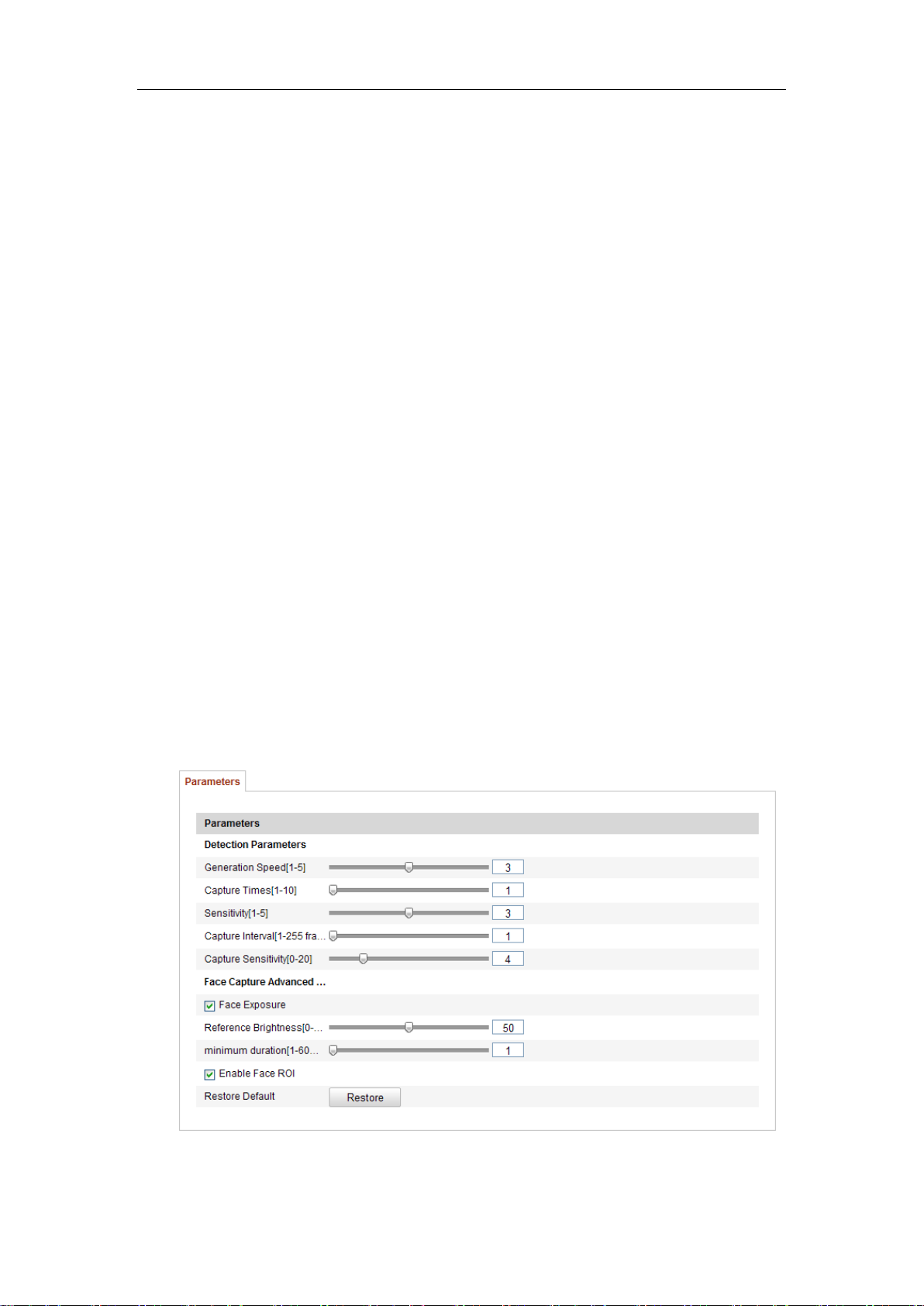
User Manual of Network Camera
every frame.
Capture Sensitivity [0~20]: The threshold the camera treats the target as a face. Only
when the face score generated by the algorithm is equal or higher than the value, the
camera will treat the target as a face. The default value of 2 is recommended.
Face Capture Advanced Parameters:
Face Exposure: Check the checkbox to enable the face exposure.
Reference Brightness [0~100]: The reference brightness of a face in the face
exposure mode. If a face is detected, the camera adjusts the face brightness according
to the value you set. The higher the value, the brighter the face is.
Minimum Duration [1~60min]: The minimum duration of the camera exposures the
face. The default value is 1 minute.
Note:
If the face exposure is enabled, please make sure the WDR function is disabled, and
the manual iris is selected.
Enable Face ROI: If the camera captures a face, the face area will be treated as the
region of interest, and the image quality of this area will be improved.
Restore Default: Click Restore to restore all the settings in advanced configuration
to the factory default.
Figure 6-61 Advanced Configuration
95
Page 97

User Manual of Network Camera
6.7.3 Heat Map
Heat map is a graphical representation of data represented by colors. The heat map
function of the camera usually be used to analyze the visit times and dwell time of
customers in a configured area.
Heat Map Configuration
Steps:
1. Enter the Heat Map configuration interface: Configuration > Advanced
Configuration > Heat Map
Figure 6-62 Heat Map Configuration
2. Select Heat Map Configuration tab to set the detailed parameters.
3. Check the checkbox of Enable Heat Map to enable the function.
4. Click Draw Area to define the area you want to count the visitors. Draw area
by left click four end-points in the live view window, and right click to finish
the area drawing. Up to 8 areas are configurable.
Note:
You can click Select All to select the whole live view window as the
configured area. Or click Delete to delete the current drawn area.
5. Configure the parameters for drawn area.
96
Page 98

User Manual of Network Camera
Detection Sensitivity [0~100]: It refers to the sensitivity of the camera
identify a target. The over-high sensitivity may cause the misinformation. It is
recommended you set the sensitivity as the default value, which is 50.
Background Update Rate [0~100]: It refers to the speed of the new scene
replaces the previous scene. E.g.: In front of a cabinet, the people besides the
cabinet will be double counted if the goods moved from the cabinet, and the
camera treats the cabinet (on which the good removed) as a new scene. The
default value of 50 is recommended.
Scene Change Level [0~100]: It refers to level of the camera responses to the
dynamic environment, e.g., a swaying curtain. The camera may treat the
swaying curtain as a target. Setting the level properly will avoid the
misinformation. The default level is 50.
Minimum Target Size [0~100]: It refers to the size of the camera identify a
target. You can set the target size according to the actual environment. The
default size is 50.
Target Track: Select ON or OFF to enable or disable the tracking of the
target.
6. Click Edit to set the arming schedule.
7. Select the linkage method by checking the checkbox of notify the surveillance
center.
8. Click Save to save the settings.
Heat Map Statistics
Steps:
1. Click Heat Map Statistics to enter the data statistics interface.
2. Select the report type by clicking the dropdown menu. Daily report, weekly
report, monthly report, and annual report are selectable.
3. Click Counting to export the data.
4. Select Statistics Result as Space Heat Map or Time Heat Map, and the
corresponding heat map will be displayed.
If you select the time heat map to list the statistics, there is an Export button
to export the data in an excel file.
97
Page 99

User Manual of Network Camera
Figure 6-63 Space Heat Map
Notes:
As shown in the figure above, red color block (255, 0, 0) indicates the most
welcome area, and blue color block (0, 0, 255) indicates the less-popular area.
It is recommended that you do not adjust the electronic lens after the
installation is completed, which may cause the inaccuracy of the data in some
degree.
6.7.4 People Counting
This chapter introduces the people counting function of the iDS camera. It is used to
calculate the number of people entered or left a certain configured area.
People Counting Configuration
Steps:
1. Enter the People Counting Configuration interface: Configuration >
Advanced Configuration > People Counting
98
Page 100

User Manual of Network Camera
Figure 6-64 People Counting Configuration
2. Select People Counting Configuration tab to set the detailed parameters.
3. Check the checkbox of Enable People Counting to enable the function.
4. Click Draw Area to define the area you want to count the entered people and
left people. Draw area by left click four end-points in the live view window,
and right click to finish the area drawing.
5. Click Entering Direction to draw the entering direction. Adjust the direction
by dragging the two red points on the arrow.
Note:
Click Delete to delete the current drawn area and entering direction.
6. Configure the parameters for drawn area.
Detection Sensitivity [0~100]: It refers to the sensitivity of the camera
recognizing a target. The higher the sensitivity, the easier the camera judges
the head or shoulder as a target. It is recommended you set the sensitivity as
the default value, which is 50.
Generation Speed (Space) [0~100]: The speed of the head or shoulder is
treated as a target. The target will not be recognized even if there is a similar
head or shoulder if you set the value lower. The default value of 50 is
recommended.
99
 Loading...