


Hikvision DS-2CD2935FWD-IS, DS-2CD2955FWD-IS User Manual
Network Fisheye Camera
User Manual
UD04808B

User Manual of Network Fisheye Camera
User Manual
COPYRIGHT ©2017 Hangzhou Hikvision Digital Technology Co., Ltd.
ALL RIGHTS RESERVED.
Any and all information, including, among others, wordings, pictures, graphs are the properties of Hangzhou Hikvision Digital Technology Co., Ltd. or its subsidiaries (hereinafter referred to be “Hikvision”). This user manual (hereinafter referred to be “the Manual”) cannot be reproduced, changed, translated, or distributed, partially or wholly, by any means, without the prior written permission of Hikvision. Unless otherwise stipulated, Hikvision does not make any warranties, guarantees or representations, express or implied, regarding to the Manual.
About this Manual
This Manual is applicable to Network Fisheye Camera.
The Manual includes instructions for using and managing the product. Pictures, charts, images and all other information hereinafter are for description and explanation only. The information contained in the Manual is subject to change, without notice, due to firmware updates or other reasons. Please find the latest version in the company website (http://overseas.hikvision.com/en/).
Please use this user manual under the guidance of professionals.
Trademarks Acknowledgement
 and other Hikvision’s trademarks and logos are the properties of Hikvision in various jurisdictions. Other trademarks and logos mentioned below are the properties of their respective owners.
Legal Disclaimer
TO THE MAXIMUM EXTENT PERMITTED BY APPLICABLE LAW, THE PRODUCT DESCRIBED, WITH ITS HARDWARE, SOFTWARE AND
FIRMWARE, IS PROVIDED “AS IS”, WITH ALL FAULTS AND ERRORS, AND
HIKVISION MAKES NO WARRANTIES, EXPRESS OR IMPLIED, INCLUDING WITHOUT LIMITATION, MERCHANTABILITY, SATISFACTORY QUALITY,
1

User Manual of Network Fisheye Camera
FITNESS FOR A PARTICULAR PURPOSE, AND NON-INFRINGEMENT OF THIRD PARTY. IN NO EVENT WILL HIKVISION, ITS DIRECTORS, OFFICERS, EMPLOYEES, OR AGENTS BE LIABLE TO YOU FOR ANY SPECIAL, CONSEQUENTIAL, INCIDENTAL, OR INDIRECT DAMAGES, INCLUDING, AMONG OTHERS, DAMAGES FOR LOSS OF BUSINESS PROFITS, BUSINESS INTERRUPTION, OR LOSS OF DATA OR DOCUMENTATION, IN CONNECTION WITH THE USE OF THIS PRODUCT, EVEN IF HIKVISION HAS BEEN ADVISED OF THE POSSIBILITY OF SUCH DAMAGES.
REGARDING TO THE PRODUCT WITH INTERNET ACCESS, THE USE OF PRODUCT SHALL BE WHOLLY AT YOUR OWN RISKS. HIKVISION SHALL NOT TAKE ANY RESPONSIBILITES FOR ABNORMAL OPERATION, PRIVACY LEAKAGE OR OTHER DAMAGES RESULTING FROM CYBER ATTACK, HACKER ATTACK, VIRUS INSPECTION, OR OTHER INTERNET SECURITY RISKS; HOWEVER, HIKVISION WILL PROVIDE TIMELY TECHNICAL SUPPORT IF REQUIRED.
SURVEILLANCE LAWS VARY BY JURISDICTION. PLEASE CHECK ALL RELEVANT LAWS IN YOUR JURISDICTION BEFORE USING THIS PRODUCT IN ORDER TO ENSURE THAT YOUR USE CONFORMS THE APPLICABLE LAW. HIKVISION SHALL NOT BE LIABLE IN THE EVENT THAT THIS PRODUCT IS USED WITH ILLEGITIMATE PURPOSES.
IN THE EVENT OF ANY CONFLICTS BETWEEN THIS MANUAL AND THE APPLICABLE LAW, THE LATER PREVAILS.
Regulatory Information
For products that do NOT support Wi-Fi or cellular data:
(Marked with a “W”, “GLT”, “GLE”, “GLF”, “GE”, “GT” or “GW” in the Part C of a product model.
Product Model Example: Part A-Part B-Part C. Part C is optional.)
FCC Information
Please take attention that changes or modification not expressly approved by the party 2

User Manual of Network Fisheye Camera
responsible for compliance could void the user’s authority to operate the equipment.
FCC compliance: This equipment has been tested and found to comply with the limits for a Class B digital device, pursuant to part 15 of the FCC Rules. These limits are designed to provide reasonable protection against harmful interference in a residential installation. This equipment generates, uses and can radiate radio frequency energy and, if not installed and used in accordance with the instructions, may cause harmful interference to radio communications. However, there is no guarantee that interference will not occur in a particular installation. If this equipment does cause harmful interference to radio or television reception, which can be determined by turning the equipment off and on, the user is encouraged to try to correct the interference by one or more of the following measures:
—Reorient or relocate the receiving antenna.
—Increase the separation between the equipment and receiver.
—Connect the equipment into an outlet on a circuit different from that to which the receiver is connected.
—Consult the dealer or an experienced radio/TV technician for help.
FCC Conditions
This device complies with part 15 of the FCC Rules. Operation is subject to the following two conditions:
1.This device may not cause harmful interference.
2.This device must accept any interference received, including interference that may cause undesired operation.
EU Conformity Statement
This product and - if applicable - the supplied accessories too are marked with "CE" and comply therefore with the applicable harmonized European standards listed under the EMC Directive
2014/30/EU, the RoHS Directive 2011/65/EU.
3

User Manual of Network Fisheye Camera
2012/19/EU (WEEE directive): Products marked with this symbol cannot be disposed of as unsorted municipal waste in the European Union. For proper recycling, return this product to your local supplier upon the purchase of equivalent new equipment, or dispose
of it at designated collection points. For more information see: www.recyclethis.info. 2006/66/EC (battery directive): This product contains a battery that cannot be disposed of as unsorted municipal waste in the European Union. See the product documentation for specific battery information. The battery is marked with this symbol, which may
include lettering to indicate cadmium (Cd), lead (Pb), or mercury (Hg). For proper recycling, return the battery to your supplier or to a designated collection point. For more information see: www.recyclethis.info.
Industry Canada ICES-003 Compliance
This device meets the CAN ICES-3 (B)/NMB-3(B) standards requirements.
For products that support Wi-Fi or cellular data:
(Marked with a “W”, “GLT”, “GLE”, “GLF”, “GE”, “GT” or “GW” in the Part C of a product model.
Product Model Example: Part A-Part B-Part C. Part C is optional.)
FCC Information
Please take attention that changes or modification not expressly approved by the party responsible for compliance could void the user’s authority to operate the equipment.
FCC compliance: This equipment has been tested and found to comply with the limits for a Class B digital device, pursuant to part 15 of the FCC Rules. These limits are designed to provide reasonable protection against harmful interference in a residential installation. This equipment generates, uses and can radiate radio frequency energy and, if not installed and used in accordance with the instructions, may cause harmful interference to radio communications. However, there is no guarantee that interference will not occur in a particular installation. If this equipment
4

User Manual of Network Fisheye Camera
does cause harmful interference to radio or television reception, which can be determined by turning the equipment off and on, the user is encouraged to try to correct the interference by one or more of the following measures:
—Reorient or relocate the receiving antenna.
—Increase the separation between the equipment and receiver.
—Connect the equipment into an outlet on a circuit different from that to which the receiver is connected.
—Consult the dealer or an experienced radio/TV technician for help.
This equipment should be installed and operated with a minimum distance 20cm between the radiator and your body.
FCC Conditions
This device complies with part 15 of the FCC Rules. Operation is subject to the following two conditions:
1.This device may not cause harmful interference.
2.This device must accept any interference received, including interference that may cause undesired operation
EU Conformity Statement
This product and - if applicable - the supplied accessories too are marked with "CE" and comply therefore with the applicable harmonized European standards listed under the Radio Equipment
Directive 2014/53/EU, EMC Directive 2014/30/EU, the RoHS Directive 2011/65/EU. 2012/19/EU (WEEE directive): Products marked with this symbol cannot be disposed of as unsorted municipal waste in the European Union. For proper recycling, return this product to your local supplier upon the purchase of equivalent new equipment, or dispose
of it at designated collection points. For more information see: www.recyclethis.info. 2006/66/EC (battery directive): This product contains a battery that cannot be disposed of as unsorted municipal waste in the European Union. See the product documentation for specific battery
5

User Manual of Network Fisheye Camera
information. The battery is marked with this symbol, which may include lettering to indicate cadmium (Cd), lead (Pb), or mercury (Hg). For proper recycling, return the battery to your supplier or to a designated collection point. For more information see: www.recyclethis.info.
Industry Canada ICES-003 Compliance
This device meets the CAN ICES-3 (B)/NMB-3(B) standards requirements.
This device complies with Industry Canada licence-exempt RSS standard(s). Operation is subject to the following two conditions:
(1)this device may not cause interference, and
(2)this device must accept any interference, including interference that may cause undesired operation of the device.
Le présent appareil est conforme aux CNR d'Industrie Canada applicables aux appareils radioexempts de licence. L'exploitation est autorisée aux deux conditions suivantes :
(1)l'appareil ne doit pas produire de brouillage, et
(2)l'utilisateur de l'appareil doit accepter tout brouillage radioélectrique subi, même si le brouillage est susceptible d'en compromettre le fonctionnement.
Under Industry Canada regulations, this radio transmitter may only operate using an antenna of a type and maximum (or lesser) gain approved for the transmitter by Industry Canada. To reduce potential radio interference to other users, the antenna type and its gain should be so chosen that the equivalent isotropically radiated power (e.i.r.p.) is not more than that necessary for successful communication.
Conformément àla réglementation d'Industrie Canada, le présent émetteur radio peut fonctionner avec une antenne d'un type et d'un gain maximal (ou inférieur) approuvé pour l'émetteur par Industrie Canada. Dans le but de réduire les risques de brouillage radioélectrique àl'intention des autres utilisateurs, il faut choisir le type d'antenne et son gain de sorte que la puissance isotrope rayonnée équivalente (p.i.r.e.) ne dépasse pas l'intensiténécessaire àl'établissement d'une communication satisfaisante.
This equipment should be installed and operated with a minimum distance 20cm
6
User Manual of Network Fisheye Camera
between the radiator and your body.
Cet équipement doit être installéet utiliséàune distance minimale de 20 cm entre le radiateur et votre corps.
Safety Instruction
These instructions are intended to ensure that the user can use the product correctly to avoid danger or property loss.
The precaution measure is divided into ‘Warnings’ and ‘Cautions’:
Warnings: Serious injury or death may be caused if any of these warnings are neglected.
Cautions: Injury or equipment damage may be caused if any of these cautions are neglected.
Warnings Follow these safeguards to Cautions Follow these precautions to prevent serious injury or death. prevent potential injury or material
damage.
Warnings:
Please adopt the power adapter which can meet the safety extra low voltage (SELV) standard. And source with 12 VDC or 24 VAC (depending on models) according to the IEC60950-1 and Limited Power Source standard.
To reduce the risk of fire or electrical shock, do not expose this product to rain or moisture.
This installation should be made by a qualified service person and should conform to all the local codes.
Please install blackouts equipment into the power supply circuit for convenient supply interruption.
Please make sure that the ceiling can support more than 50(N) Newton gravities if
the camera is fixed to the ceiling.
7

User Manual of Network Fisheye Camera
If the product does not work properly, please contact your dealer or the nearest service center. Never attempt to disassemble the camera yourself. (We shall not assume any responsibility for problems caused by unauthorized repair or maintenance.)
Cautions:
Make sure the power supply voltage is correct before using the camera.
Do not drop the camera or subject it to physical shock.
Do not touch sensor modules with fingers. If cleaning is necessary, use a clean cloth with a bit of ethanol and wipe it gently. If the camera will not be used for an extended period of time, put on the lens cap to protect the sensor from dirt.
Do not aim the camera lens at the strong light such as sun or incandescent lamp. The strong light can cause fatal damage to the camera.
The sensor may be burned out by a laser beam, so when any laser equipment is being used, make sure that the surface of the sensor not be exposed to the laser beam.
Do not place the camera in extremely hot, cold temperatures (the operating temperature should be between -10°C ~ 40°C), dusty or damp environment, and do not expose it to high electromagnetic radiation.
To avoid heat accumulation, good ventilation is required for a proper operating environment.
Keep the camera away from water and any liquid.
While shipping, the camera should be packed in its original packing.
Improper use or replacement of the battery may result in hazard of explosion. Please use the manufacturer recommended battery type.
Notes:
For the camera supports IR, you are required to pay attention to the following
precautions to prevent IR reflection:
Dust or grease on the dome cover will cause IR reflection. Please do not remove
8

User Manual of Network Fisheye Camera
the dome cover film until the installation is finished. If there is dust or grease on the dome cover, clean the dome cover with clean soft cloth and isopropyl alcohol.
Make certain the installation location does not have reflective surfaces of objects too close to the camera. The IR light from the camera may reflect back into the lens causing reflection.
The foam ring around the lens must be seated flush against the inner surface of the bubble to isolate the lens from the IR LEDS. Fasten the dome cover to camera body so that the foam ring and the dome cover are attached seamlessly.
0504051070218
9
User Manual of Network Fisheye Camera
Table of Contents
Chapter 1 |
System Requirement.......................................................................... |
12 |
|
Chapter 2 |
Network Connection.......................................................................... |
13 |
|
2.1 |
Setting the Network Camera over the LAN...................................................... |
13 |
|
2.1.1 |
Wiring over the LAN........................................................................................................ |
13 |
|
2.1.2 |
|
Creating a Password........................................................................................................ |
14 |
2.2 |
Setting the Network Camera over the WAN .................................................... |
21 |
|
2.2.1 |
|
Static IP Connection........................................................................................................ |
21 |
2.2.2 |
|
Dynamic IP Connection................................................................................................... |
22 |
Chapter 3 |
Access to the Network Camera........................................................... |
24 |
|
3.1 |
Accessing by Web Browsers............................................................................ |
24 |
|
3.2 |
Accessing by Client Software .......................................................................... |
25 |
|
Chapter 4 |
Wi-Fi Settings ................................................................................... |
26 |
|
Chapter 5 |
Live View .......................................................................................... |
31 |
|
5.1 |
Live View Page ............................................................................................... |
31 |
|
5.2 |
Starting Live View .......................................................................................... |
34 |
|
5.3 |
Recording and Capturing Pictures Manually .................................................... |
35 |
|
5.4 |
Operating PTZ Control.................................................................................... |
35 |
|
5.4.1 |
|
PTZ Control Panel............................................................................................................ |
36 |
5.4.2 |
|
Setting/Calling/Deleting a Preset ................................................................................... |
38 |
5.4.3 |
|
Setting/Calling/Deleting a Patrol .................................................................................... |
40 |
Chapter 6 |
Network Camera Configuration ........................................................ |
42 |
|
6.1 |
Configuring Local Parameters ......................................................................... |
42 |
|
6.2 |
Configuring System Settings ........................................................................... |
44 |
|
6.2.1 |
|
Viewing Basic Information .............................................................................................. |
44 |
6.2.2 |
Time and DST Settings .................................................................................................... |
45 |
|
6.2.3 |
|
RS-232 Settings ............................................................................................................... |
47 |
6.2.4 |
|
RS-485 Settings ............................................................................................................... |
48 |
6.2.5 |
|
Upgrade and Maintenance ............................................................................................. |
49 |
6.2.6 |
|
Log Searching.................................................................................................................. |
50 |
6.2.7 |
|
System Service Settings .................................................................................................. |
51 |
6.2.8 |
|
Authentication ................................................................................................................ |
52 |
6.2.9 |
|
IP Address Filter .............................................................................................................. |
52 |
6.2.10 |
Security Service............................................................................................................... |
54 |
|
6.2.11 |
User Management .......................................................................................................... |
54 |
|
6.3 |
Configuring Network Settings ......................................................................... |
58 |
|
6.3.1 |
|
Configuring TCP/IP Settings ............................................................................................ |
58 |
10

User Manual of Network Fisheye Camera
6.3.2 |
Configuring Port Settings ................................................................................................ |
59 |
6.3.3 |
Configuring PPPoE Settings............................................................................................. |
60 |
6.3.4 |
Configuring DDNS Settings.............................................................................................. |
61 |
6.3.5 |
Configuring NAT (Network Address Translation) Settings............................................... |
63 |
6.3.6 |
Configuring SNMP Settings ............................................................................................. |
64 |
6.3.7 |
Configuring FTP Settings ................................................................................................. |
67 |
6.3.8 |
Email Settings ................................................................................................................. |
69 |
6.3.9 |
Configuring HTTPS Settings............................................................................................. |
71 |
6.3.10 |
Configuring QoS Settings ................................................................................................ |
74 |
6.3.11 |
Configuring 802.1X Settings............................................................................................ |
74 |
6.3.12 |
Configuring Platform Access ........................................................................................... |
76 |
6.4 |
Configuring Video and Audio Settings............................................................. |
77 |
6.4.1 |
Configuring Video Settings.............................................................................................. |
77 |
6.4.2 |
Configuring Audio Settings ............................................................................................. |
81 |
6.4.3 |
Configuring ROI Encoding ............................................................................................... |
82 |
6.4.4 |
Display Info.on Stream.................................................................................................... |
84 |
6.5 |
Configuring Image Parameters........................................................................ |
84 |
6.5.1 |
Configuring Display Settings ........................................................................................... |
84 |
6.5.2 |
Configuring OSD Settings................................................................................................ |
89 |
6.5.3 |
Configuring Privacy Mask................................................................................................ |
90 |
6.6 |
Configuring Event Settings.............................................................................. |
91 |
|
6.6.1 |
|
Configuring Motion Detection ........................................................................................ |
92 |
6.6.2 |
Configuring Video Tampering Alarm ............................................................................... |
98 |
|
6.6.3 |
|
Configuring Alarm Input ................................................................................................. |
99 |
6.6.4 |
|
Configuring Alarm Output ............................................................................................ |
100 |
6.6.5 |
|
Handling Exception ....................................................................................................... |
102 |
6.6.6 |
Configuring Line Crossing Detection ............................................................................. |
102 |
|
6.6.7 |
|
Configuring Intrusion Detection ................................................................................... |
104 |
Chapter 7 |
Storage Settings .............................................................................. |
107 |
|
7.1 |
Configuring Recording Schedule ................................................................... |
107 |
|
7.2 |
Configuring Capture Setting.......................................................................... |
111 |
|
7.3 |
Configuring Net HDD.................................................................................... |
112 |
|
7.4 |
Memory Card Detection ............................................................................... |
114 |
|
Chapter 8 |
Playback ......................................................................................... |
117 |
|
Chapter 9 |
Picture ............................................................................................ |
120 |
|
Appendix |
|
........................................................................................................... |
121 |
Appendix ...............................................................1 SADP Software Introduction |
121 |
||
Appendix ......................................................................................2 Port Mapping |
124 |
||
11

User Manual of Network Fisheye Camera
Chapter 1 System Requirement
Operating System: Microsoft Windows XP SP1 and above version
CPU: 2.0 GHz or higher
RAM: 1G or higher
Display: 1024×768 resolution or higher
Web Browser: Internet Explorer 8.0 and above version, Apple Safari 5.0.2 and above version, Mozilla Firefox 5.0 and above version and Google Chrome 18 and above version
12

User Manual of Network Fisheye Camera
Chapter 2 Network Connection
Note:
You shall acknowledge that the use of the product with Internet access might be under network security risks. For avoidance of any network attacks and information leakage, please strengthen your own protection. If the product does not work properly, please contact with your dealer or the nearest service center.
To ensure the network security of the network camera, we recommend you to have the network camera assessed and maintained termly. You can contact us if you need such service.
Before you start:
If you want to set the network camera via a LAN (Local Area Network), please refer to Section 2.1 Setting the Network Camera over the LAN.
If you want to set the network camera via a WAN (Wide Area Network), please refer to Section 2.2 Setting the Network Camera over the WAN.
2.1 Setting the Network Camera over the LAN
Purpose:
To view and configure the camera via a LAN, you need to connect the network camera in the same subnet with your computer, and install the SADP or iVMS-4200 software to search and change the IP of the network camera.
Note: For the detailed introduction of SADP, please refer to Appendix 1.
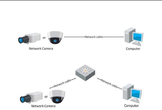
2.1.1 Wiring over the LAN
The following figures show the two ways of cable connection of a network camera and a computer:
Purpose:
To test the network camera, you can directly connect the network camera to the computer with a network cable as shown in Figure 2-1.
13
User Manual of Network Fisheye Camera
Refer to the Figure 2-2 to set network camera over the LAN via a switch or a router.
Figure 2-1 Connecting Directly
Figure 2-2 Connecting via a Switch or a Router
2.1.2 Creating a Password
You are required to activate the camera first by setting a strong password for it before you can use the camera.
Creating a Password via Web Browser, Creating a Password via SADP, and Creating a Password via Client Software are all supported.
Creating a Password via Web Browser
Steps:
1.Power on the camera, and connect the camera to the network.
2.Input the IP address into the address bar of the web browser, and click Enter to enter the activation interface.
Notes:
The default IP address of the camera is 192.168.1.64.
For the camera enables the DHCP by default, the IP address is allocated automatically. And you need to activate the camera via SADP software. Please refer to the following chapter for Activation via SADP.
14
User Manual of Network Fisheye Camera
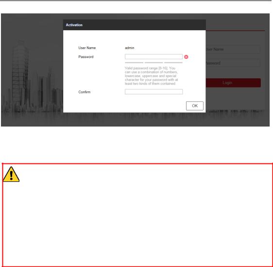
Figure 2-3 Creating a Password via Web Browser 3. Create a password and input the password into the password field.
STRONG PASSWORD RECOMMENDED– We highly recommend you create a strong password of your own choosing (using a minimum of 8 characters, including at least three of the following categories: upper case letters, lower case letters, numbers, and special characters) in order to increase the security of your product. And we recommend you reset your password regularly, especially in the high security system, resetting the password monthly or weekly can better protect your product.
4.Confirm the password.
5.Click OK to save the password and enter the live view interface.
Creating a Password via SADP Software
SADP software is used for detecting the online device, activating the camera, and resetting the password.
Get the SADP software from the supplied disk or the official website, and install the SADP according to the prompts. Follow the steps to activate the camera.
Steps:
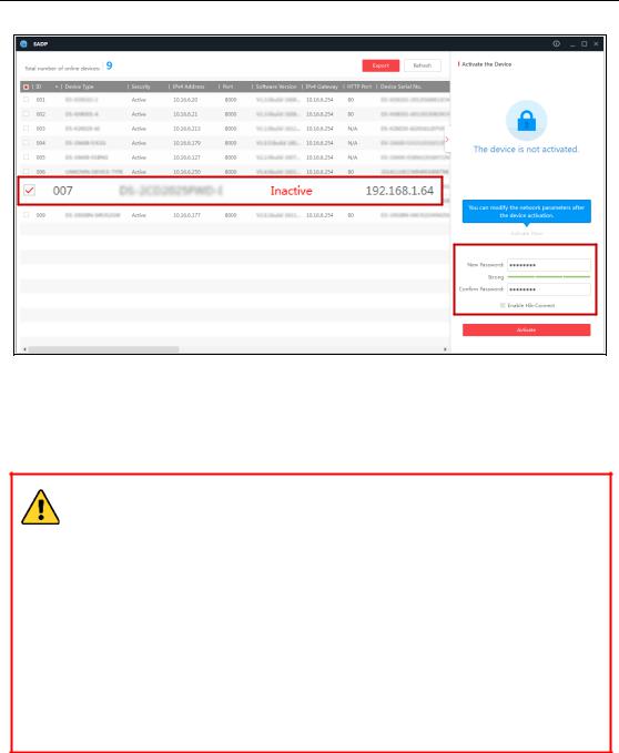
1.Run the SADP software to search the online devices.
2.Check the device status from the device list, and select the inactive device.
15
User Manual of Network Fisheye Camera
Select inactive device.
Input and confirm password.
Figure 2-4 SADP Interface
3. Create a password and input the password in the password field, and confirm the password.
STRONG PASSWORD RECOMMENDED– We highly recommend you create a strong password of your own choosing (using a minimum of 8 characters, including at least three of the following categories: upper case letters, lower case letters, numbers, and special characters) in order to increase the security of your product. And we recommend you reset your password regularly, especially in the high security system, resetting the password monthly or weekly can better protect your product.
Note:
You can enable the Hik-Connect service for the device during activation. 4. Click Activate to start activation.
You can check whether the activation is completed on the popup window. If activation failed, please make sure that the password meets the requirement and try again.
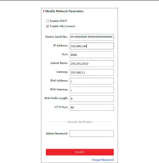
5. Change the device IP address to the same subnet with your computer by either modifying the IP address manually or checking the checkbox of Enable DHCP.
16
User Manual of Network Fisheye Camera
Figure 2-5 Modify the IP Address
6. Input the admin password and click Modify to activate your IP address modification.
The batch IP address modification is supported by the SADP. Refer to the user manual of SADP for details.
Creating a Password via Client Software
The client software is versatile video management software for multiple kinds of devices.
Get the client software from the supplied disk or the official website, and install the software according to the prompts. Follow the steps to activate the camera.
Steps:
17
User Manual of Network Fisheye Camera
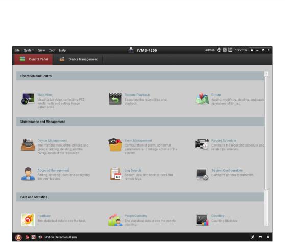
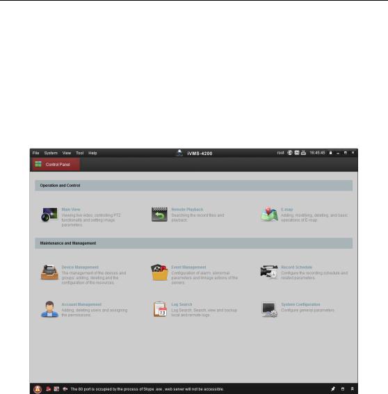
1. Run the client software and the control panel of the software pops up, as shown in the figure below.
Figure 2-6 Control Panel
2. Click the Device Management icon to enter the Device Management interface, as shown in the figure below.
18

User Manual of Network Fisheye Camera
Figure 2-7 Device Management Interface
3.Check the device status from the device list, and select an inactive device.
4.Click the Activate button to pop up the Activation interface.
5.Create a password and input the password in the password field, and confirm the password.
STRONG PASSWORD RECOMMENDED– We highly recommend you create a strong password of your own choosing (using a minimum of 8 characters, including at least three of the following categories: upper case letters, lower case letters, numbers, and special characters) in order to increase the security of your product. We recommend you reset your password regularly, especially in the high security system, resetting the password monthly or weekly can better protect your product.
19
User Manual of Network Fisheye Camera
Figure 2-8 Activation Interface (Client Software)
6.Click OK button to start activation.
7.Click the Modify Netinfo button to pop up the Network Parameter Modification interface, as shown in the figure below.
Figure 2-9 Modifying the Network Parameters
8.Change the device IP address to the same subnet with your computer by either modifying the IP address manually or checking the checkbox of Enable DHCP.
9.Input the password to activate your IP address modification.
20

User Manual of Network Fisheye Camera
2.2 Setting the Network Camera over the WAN
Purpose:
This section explains how to connect the network camera to the WAN with a static IP or a dynamic IP.
2.2.1 Static IP Connection
Before you start:
Please apply a static IP from an ISP (Internet Service Provider). With the static IP address, you can connect the network camera via a router or connect it to the WAN directly.
Connecting the network camera via a router
Steps:
1.Connect the network camera to the router.
2.Assign a LAN IP address, the subnet mask and the gateway. Refer to Section 2.1.2 for detailed IP address configuration of the network camera.
3.Save the static IP in the router.
4.Set port mapping, e.g., 80, 8000, and 554 ports. The steps for port mapping vary according to the different routers. Please call the router manufacturer for
assistance with port mapping.
Note: Refer to Appendix 2 for detailed information about port mapping.
5.Visit the network camera through a web browser or the client software over the internet.
Figure 2-10 Accessing the Camera through Router with Static IP
Connecting the network camera with static IP directly
You can also save the static IP in the camera and directly connect it to the internet 21

User Manual of Network Fisheye Camera
without using a router. Refer to Section 2.1.2 for detailed IP address configuration of the network camera.
Figure 2-11 Accessing the Camera with Static IP Directly
2.2.2 Dynamic IP Connection
Before you start:
Please apply a dynamic IP from an ISP. With the dynamic IP address, you can connect the network camera to a modem or a router.
Connecting the network camera via a router
Steps:
1.Connect the network camera to the router.
2.In the camera, assign a LAN IP address, the subnet mask and the gateway. Refer to Section 2.1.2 for detailed IP address configuration of the network camera.
3.In the router, set the PPPoE user name, password and confirm the password.
4.Set port mapping. E.g. 80, 8000, and 554 ports. The steps for port mapping vary depending on different routers. Please call the router manufacturer for assistance with port mapping.
Note: Refer to Appendix 2 for detailed information about port mapping.
5.Apply a domain name from a domain name provider.
6.Configure the DDNS settings in the setting interface of the router.
7.Visit the camera via the applied domain name.
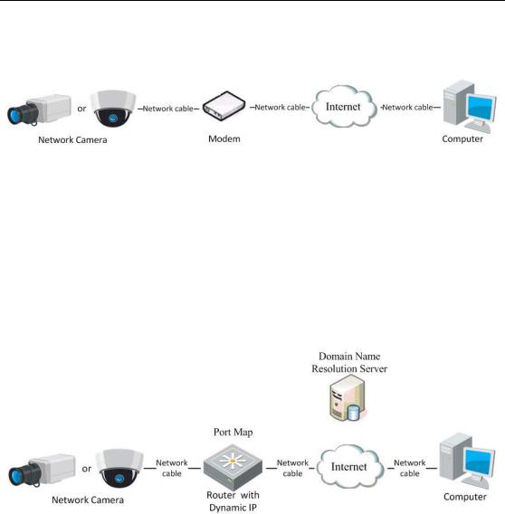
Connecting the network camera via a modem
Purpose:
This camera supports the PPPoE auto dial-up function. The camera gets a public IP address by ADSL dial-up after the camera is connected to a modem. You need to 22
User Manual of Network Fisheye Camera
configure the PPPoE parameters of the network camera. Refer to Section 6.3.3
Configuring PPPoE Settings for detailed configuration.
Figure 2-12 Accessing the Camera with Dynamic IP
Note: The obtained IP address is dynamically assigned via PPPoE, so the IP address always changes after rebooting the camera. To solve the inconvenience of the dynamic IP, you need to get a domain name from the DDNS provider (E.g. DynDns.com). Please follow the steps below for normal domain name resolution and private domain name resolution to solve the problem.
Normal Domain Name Resolution
Figure 2-13 Normal Domain Name Resolution
Steps:
1.Apply a domain name from a domain name provider.
2.Configure the DDNS settings in the DDNS Settings interface of the network camera. Refer to Section 6.3.4 Configuring DDNS Settings for detailed configuration.
3.Visit the camera via the applied domain name.
23
User Manual of Network Fisheye Camera
Chapter 3 Access to the Network Camera
3.1 Accessing by Web Browsers
Steps:
1.Open the web browser.
2.Input the IP address of the network camera in the address bar, e.g., 192.168.1.64 and press the Enter key to enter the login interface.
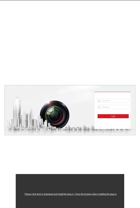
3.Input the user name and password and click Login.
Figure 3-1 Login Interface
Note:
Switch the display language from the upper-right corner among different languages.
4.Install the plug-in before viewing the live video and operating the camera. Please follow the installation prompts to install the plug-in.
Figure 3-2 Download and Install Plug-in
Note: You may have to close the web browser to install the plug-in. Please reopen the web browser and log in again after installing the plug-in.
24
User Manual of Network Fisheye Camera
3.2 Accessing by Client Software
The product CD contains the iVMS-4200 client software. You can view the live video and manage the camera with the software.
Follow the installation prompts to install the software. The control panel interface of iVMS-4200 client software is shown as bellow.
Figure 3-3 iVMS-4200 Client Software
Note: For detailed information about the software, please refer to the user manual of the iVMS-4200 Client Software.
25

User Manual of Network Fisheye Camera
Chapter 4 Wi-Fi Settings
Purpose:
By connecting to the wireless network, you don’t need to use cable of any kind for network connection, which is very convenient for the actual surveillance application. Two connection modes are supported. Choose a mode as desired and perform the steps to configure the Wi-Fi.
Note: This chapter is only applicable for the cameras with the built-in Wi-Fi module.
Wireless Connection in Manage Mode
Steps:
1.Enter the Wi-Fi Settings interface:
Configuration > Network > Advanced Settings > Wi-Fi
2.Click Search to search the online wireless connections as the figure below.
Figure 4-1 Wi-Fi list
3.Click to choose a wireless connection on the list.
26
User Manual of Network Fisheye Camera
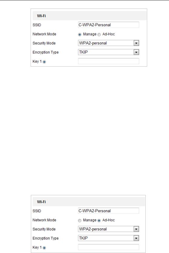
Figure 4-2 Wi-Fi SettingManage Mode
4.Check the radio button to select the Network mode as Manage, and the Security
mode of the network is automatically shown when you select the wireless
network, please don’t change it manually.
Note: These parameters are exactly identical with those of the router.
5.Enter the key to connect the wireless network. The key should be that of the wireless network connection you set on the router.
Wireless Connection in Ad-hoc Mode
If you choose the Ad-hoc mode, you don’t need to connect the wireless camera via a router. The scenario is the same as you connect the camera and the PC directly with a network cable.
Steps:
1. Choose Ad-hoc mode.
Figure 4-3 Wi-Fi Setting- Ad-hoc
2.Customize a SSID for the camera.
3.Choose the Security Mode of the wireless connection.
27
User Manual of Network Fisheye Camera
4.Enable the wireless connection function for your PC.
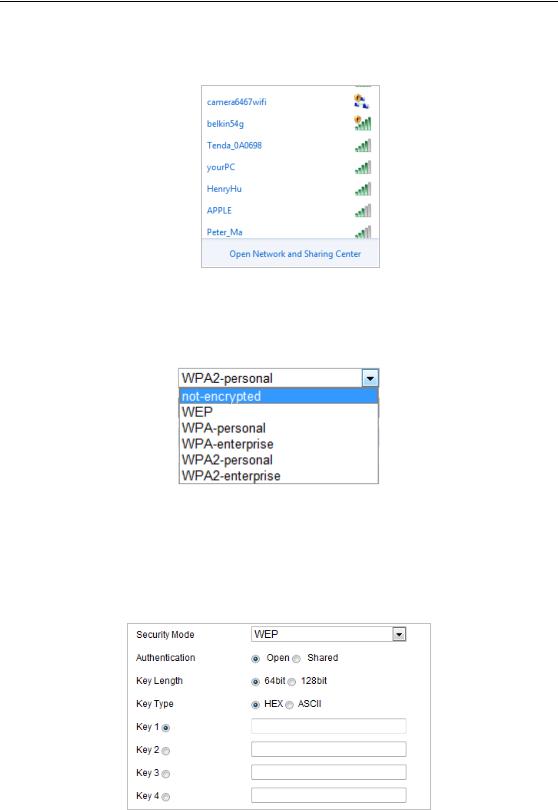
5.On the PC side, search the network and you can see the SSID of the camera listed.
Figure 4-4 Ad-hoc Connection Point
6. Choose the SSID and connect.
Security Mode Description:
Figure 4-5 Security Mode
You can choose the Security Mode as not-encrypted, WEP, WPA-personal, WPA-enterprise, WPA2-personal, and WPA2-enterprise.
WEP mode:
Figure 4-6 WEP Mode
Authentication - Select Open or Shared Key System Authentication, depending on the method used by your access point. Not all access points have this option, in
which case they probably use Open System, which is sometimes known as SSID 28

User Manual of Network Fisheye Camera
Authentication.
Key length - This sets the length of the key used for the wireless encryption, 64 or 128 bit. The encryption key length can sometimes be shown as 40/64 and 104/128.
Key type - The key types available depend on the access point being used. The following options are available:
HEX - Allows you to manually enter the hex key.
ASCII - In this method the string must be exactly 5 characters for 64-bit WEP and 13 characters for 128-bit WEP.
WPA-personal and WPA2-personal Mode:
Enter the required Pre-shared Key for the access point, which can be a hexadecimal number or a passphrase.
Figure 4-7 Security Mode- WPA-personal
WPAenterprise and WPA2-enterprise Mode:
Choose the type of client/server authentication being used by the access point, EAP-TLS or EAP-PEAP.
EAP-TLS:
Figure 4-8 EAP-TLS
29
 Loading...