


Hikvision DS-2CD2D21G0-M-D-NF-2-8mm, DS-2CD2D21G0-M-D-NF-4mm User Manual

DS-2CD2D21G0/M-D/NF
Pinhole and Covert
Mini Network Cameras
User Manual

DS-2CD2D21G0/M-D/NF User Manual
About this Manual
This Manual is applicable to the DS-2CD2D21G0/M-D/NF Pinhole and Covert Mini Network Cameras.
The Manual includes instructions for using and managing the product. Pictures, charts, images and all other information
hereinafter are for description and explanation only. The information contained in the Manual is subject to change, without
notice, due to firmware updates or other reasons. Please find the latest version in the company Web site.
Please use this user manual under the guidance of professionals.
Legal Disclaimer
TO THE MAXIMUM EXTENT PERMITTED BY APPLICABLE LAW, THE PRODUCT DESCRIBED, WITH ITS HARDWARE,
SOFTWARE AND FIRMWARE, IS PROVIDED "AS IS", WITH ALL FAULTS AND ERRORS, AND OUR COMPANY MAKES
NO WARRANTIES, EXPRESS OR IMPLIED, INCLUDING WITHOUT LIMITATION, MERCHANTABILITY, SATISFACTORY
QUALITY, FITNESS FOR A PARTICULAR PURPOSE, AND NON-INFRINGEMENT OF THIRD PARTY. IN NO EVENT
WILL OUR COMPANY, ITS DIRECTORS, OFFICERS, EMPLOYEES, OR AGENTS BE LIABLE TO YOU FOR ANY
SPECIAL, CONSEQUENTIAL, INCIDENTAL, OR INDIRECT DAMAGES, INCLUDING, AMONG OTHERS, DAMAGES
FOR LOSS OF BUSINESS PROFITS, BUSINESS INTERRUPTION, OR LOSS OF DATA OR DOCUMENTATION, IN
CONNECTION WITH THE USE OF THIS PRODUCT, EVEN IF OUR COMPANY HAS BEEN ADVISED OF THE
POSSIBILITY OF SUCH DAMAGES.
REGARDING TO THE PRODUCT WITH INTERNET ACCESS, THE USE OF PRODUCT SHALL BE WHOLLY AT YOUR
OWN RISKS. OUR COMPANY SHALL NOT TAKE ANY RESPONSIBILITIES FOR ABNORMAL OPERATION, PRIVACY
LEAKAGE OR OTHER DAMAGES RESULTING FROM CYBER ATTACK, HACKER ATTACK, VIRUS INSPECTION, OR
OTHER INTERNET SECURITY RISKS; HOWEVER, OUR COMPANY WILL PROVIDE TIMELY TECHNICAL SUPPORT IF
REQUIRED.
SURVEILLANCE LAWS VARY BY JURISDICTION. PLEASE CHECK ALL RELEVANT LAWS IN YOUR JURISDICTION
BEFORE USING THIS PRODUCT IN ORDER TO ENSURE THAT YOUR USE CONFORMS THE APPLICABLE LAW.
OUR COMPANY SHALL NOT BE LIABLE IN THE EVENT THAT THIS PRODUCT IS USED WITH ILLEGITIMATE
PURPOSES.
IN THE EVENT OF ANY CONFLICTS BETWEEN THIS MANUAL AND THE APPLICABLE LAW, THE LATER PREVAILS.
Notice:
If camera fails to synchronize local time with that of the network, you need to set up camera time manually. Visit the
camera and enter system setting interface for time setting.
Safety Instruction
These instructions are intended to ensure that the user can use the product correctly to avoid danger or property loss.
The precaution measure is divided into “Warnings” and “Cautions”:
UM DS-2CD2D21G0/M-D/NF 020319NA 1
DS-2CD2D21G0/M-D/NF User Manual
Warnings: Serious injury or death may be caused if any of these warnings are neglected.
Cautions: Injury or equipment damage may be caused if any of these cautions are neglected.
WARNINGS! Follow these safeguards to
prevent serious injury or death.
CAUTIONS! Follow these precautions to
prevent potential injury or material damage.
WARNINGS
•
Please use a power adapter that can meet the safety extra low voltage (SELV) standard. Source with 12 VDC or 24
VAC (depending on model) according to the IEC60950-1 and Limited Power Source standard.
•
To reduce the risk of fire or electrical shock, do not expose this product to rain or moisture.
•
This installation should be made by a qualified service person and should conform to all local codes.
•
Please install blackout equipment into the power supply circuit to address supply interruption.
•
Make sure that the ceiling can support more than 50 (N) Newton gravities if the camera is fixed to the ceiling.
•
If the product does not work properly, please contact your dealer or the nearest service center. Never attempt to
disassemble the camera yourself. (We shall not assume any responsibility for problems caused by unauthorized repair
or maintenance.)
CAUTIONS!
•
Make sure the power supply voltage is correct before using the camera.
•
Do not drop the camera or subject it to physical shock.
•
Do not touch sensor modules with fingers. If cleaning is necessary, use a clean cloth with a bit of ethanol and wipe it
gently. If the camera will not be used for an extended period of time, put on the lens cap to protect the sensor from dirt.
•
Do not aim the camera lens at a strong light such as the sun or an incandescent lamp. A strong light can cause fatal
damage to the camera.
•
The sensor may be burned out by a laser beam, so when any laser equipment is being used, make sure that the
surface of the sensor not be exposed to the laser beam.
•
Do not place the camera in extremely hot or cold temperatures (refer to product specification for working temperature),
dusty or damp environment, and do not expose it to high electromagnetic radiation.
UM DS-2CD2D21G0/M-D/NF 020319NA 2

DS-2CD2D21G0/M-D/NF User Manual
•
To avoid heat accumulation, ensure there is good ventilation to the device.
•
Keep the camera away from water and any liquids.
•
While shipping, pack the camera in its original, or equivalent, packing materials or packing of the same texture.
•
Improper use or replacement of the battery may result in hazard of explosion. Please use the manufacturer
recommended battery type.
NOTE: For cameras that support IR, you are required to pay attention to the following precautions to prevent
IR reflection:
•
Dust or grease on the dome cover will cause IR reflection. Please do not remove the dome cover film until the
installation is finished. If there is dust or grease on the dome cover, clean the dome cover with a clean soft cloth and
isopropyl alcohol.
•
Make certain the installation location does not have reflective surfaces of objects too close to the camera. The IR light
from the camera may reflect back into the lens, causing reflection.
•
The foam ring around the lens must be seated flush against the inner surface of the bubble to isolate the lens from the
IR LEDS. Fasten the dome cover to the camera body so that the foam ring and the dome cover are attached
seamlessly.
UM DS-2CD2D21G0/M-D/NF 020319NA 3
DS-2CD2D21G0/M-D/NF User Manual
Table of Contents
Chapter 1 General ............................................................................................................................................................. 8
Chapter 2 Network Connection ........................................................................................................................................ 9
Chapter 3 Access to the Network Camera .................................................................................................................... 19
Chapter 4 Wi-Fi Settings ................................................................................................................................................. 21
Chapter 5 Live View ........................................................................................................................................................ 30
Chapter 6 Network Camera Configuration .................................................................................................................... 37
UM DS-2CD2D21G0/M-D/NF 020319NA 4
DS-2CD2D21G0/M-D/NF User Manual
Chapter 7 Network Settings ............................................................................................................................................ 55
Chapter 8 Video/Audio Settings ..................................................................................................................................... 76
Chapter 9 Image Settings ............................................................................................................................................... 84
UM DS-2CD2D21G0/M-D/NF 020319NA 5
DS-2CD2D21G0/M-D/NF User Manual
Chapter 10 Event Settings ................................................................................................................................................ 92
Chapter 11 Storage Settings .......................................................................................................................................... 137
Chapter 12 Playback ....................................................................................................................................................... 146
Chapter 13 Picture ........................................................................................................................................................... 148
Chapter 14 Application ................................................................................................................................................... 149
UM DS-2CD2D21G0/M-D/NF 020319NA 6

DS-2CD2D21G0/M-D/NF User Manual
Appendix 156
UM DS-2CD2D21G0/M-D/NF 020319NA 7

DS-2CD2D21G0/M-D/NF User Manual
Chapter 1 General
System Requirement
Operating System
•
Microsoft Windows XP SP1 and above version
•
CPU: 2.0 GHz or higher
•
RAM: 1 GB or higher
•
Display: 1024 × 768 resolution or higher
•
Web Browser (For cameras that supports plug-in free live view): Internet Explorer 8-11, Mozilla Firefox 30.0 and above
version, and Google Chrome 41.0 and above version
NOTES:
» For Google Chrome 45 and above versions or Mozilla Firefox 52 and above versions that are plug-in free,
Picture and Playback functions are hidden.
» To use mentioned functions via a Web browser, change to their lower version, or change to Internet Explorer
8.0 and above version.
» For cameras that do NOT support plug-in free live view, Internet Explorer 8 - 11, Mozilla Firefox 30.0 - 51, and
Google Chrome 41.0 - 44.
UM DS-2CD2D21G0/M-D/NF 020319NA 8
DS-2CD2D21G0/M-D/NF User Manual
Chapter 2 Network Connection
NOTES:
» You shall acknowledge that the use of the product with Internet access might be under network security risks.
For avoidance of any network attacks and information leakage, please strengthen your own protection. If the
product does not work properly, please contact with your dealer or the nearest service center.
» To ensure the network security of the network camera, we recommend you to have the network camera
assessed and maintained periodically. You can contact us if you need such service.
Before you start:
•
If you want to set the network camera via a LAN (Local Area Network), please refer to Section 2.1 Setting the Network
Camera over the LAN.
•
If you want to set the network camera via a WAN (Wide Area Network), please refer to Section 2.2 Setting the
Network Camera over the WAN.
Setting the Network Camera over a LAN
Purpose:
To view and configure the camera via a LAN, you need to connect the network camera in the same subnet as your
computer, and install the SADP or Hik-Connect software to search and change the IP of the network camera.
NOTE: For detailed introduction to SADP, refer to Appendix 1.
Wiring over the LAN
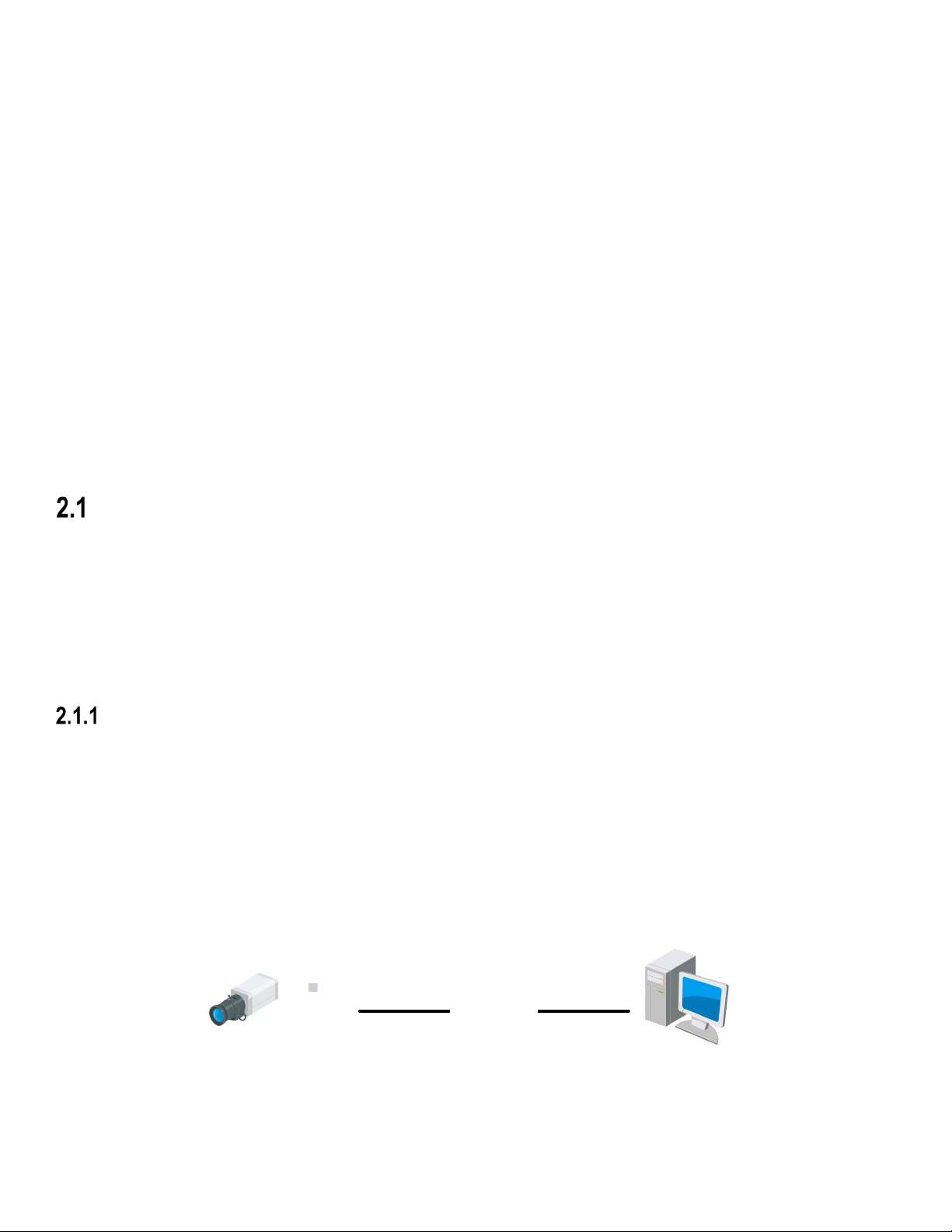
The following figures show the two ways of cable connection of a network camera and a computer:
Purpose:
•
To test the network camera, you can directly connect the network camera to the computer with a network cable as
shown in Figure 2-1.
•
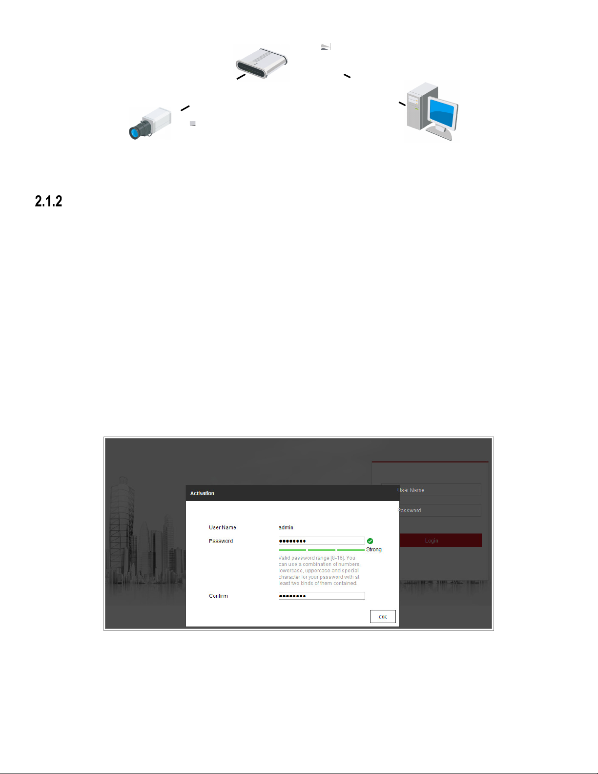
Refer to the Figure 2-2 to set network camera over the LAN via a switch or a router.
or
Network Camera
Network Cable
Computer
Figure 1, Connecting Directly
UM DS-2CD2D21G0/M-D/NF 020319NA 9
DS-2CD2D21G0/M-D/NF User Manual
or
or
N
e
l
b
a
C
k
r
o
w
t
e
N
e
t
w
o
r
k
C
a
b
l
e
Network Camera
Computer
Figure 2, Connecting via a Switch or a Router
Activating the Camera
You are required to activate the camera first by setting a strong password for it before you can use the camera. Activation
via Web Browser, Activation via SADP, and Activation via Client Software are all supported.
•
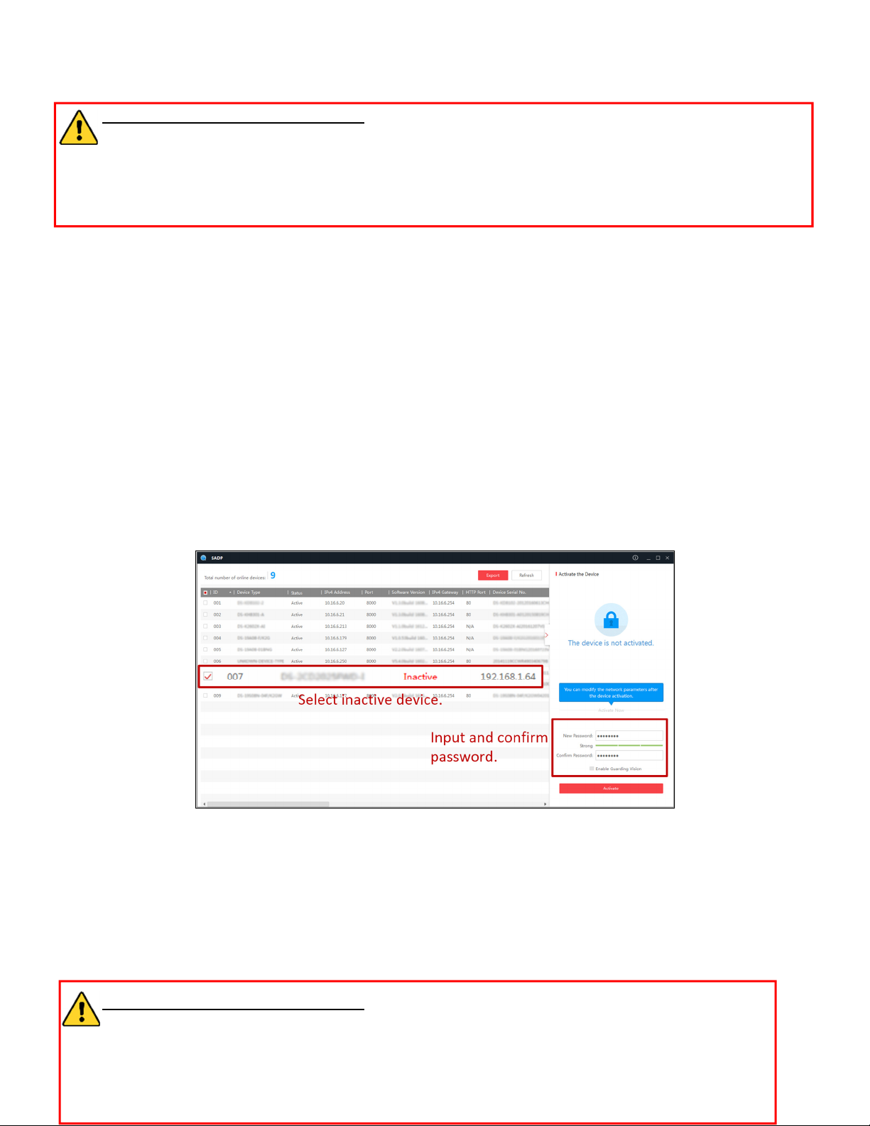
Activation via Web Browser
1. Power on the camera, and connect the camera to the network.
2. Input the IP address into the address bar of the web browser, and click Enter to enter the activation interface.
NOTES:
» The default IP address of the camera is 192.168.1.64.
» The computer and the camera should belong to the same subnet.
» For cameras with DHCP enabled by default, use the SADP software to search for the IP address.
Figure 3, Activation via Web Browser
3. Create a password and input it into the password field. A password containing a user name is not allowed.
UM DS-2CD2D21G0/M-D/NF 020319NA 10
DS-2CD2D21G0/M-D/NF User Manual
STRONG PASSWORD RECOMMENDED – We highly recommend that you create a strong password of
your own choosing (using a minimum of eight characters, including at least three of the following categories:
upper case letters, lower case letters, numbers, and special characters) in order to increase the security of
your product. We also recommend that you reset your password regularly. Especially high security systems,
resetting the password monthly or weekly can better protect your product.
4. Confirm the password.
5. Click OK to save the password and enter the live view interface.
•
Activation via SADP Software
SADP software is used for detecting the online device, activating the camera, and resetting the password.
Get the SADP software from the supplied disk or the official Web site, and install the SADP according to the prompts.
Follow the steps to activate the camera.
1. Run the SADP software to search the online devices.
2. Check the device status from the device list, and select the inactive device.
Figure 4, SADP Interface
NOTE: SADP software supports activating the camera in batches. See the SADP software user manual for
details.
3. Create a password and input the password in the password field, and confirm the password. A password containing
a user name is not allowed.
STRONG PASSWORD RECOMMENDED – We highly recommend that you create a strong password of
your own choosing (using a minimum of eight characters, including at least three of the following categories:
upper case letters, lower case letters, numbers, and special characters) in order to increase the security of
UM DS-2CD2D21G0/M-D/NF 020319NA 11
DS-2CD2D21G0/M-D/NF User Manual
your product. We also recommend that you reset your password regularly. Especially in high security
systems, resetting the password monthly or weekly can better protect your product.
NOTE: You can enable the Hik-Connect service for the device during activation.
4. Click Activate to save the password. You can check whether the activation is completed on the pop-up window. If
activation failed, make sure that the password meets the requirement and try again.
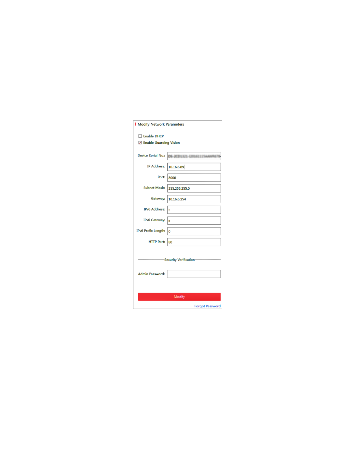
5. Change the device IP address to the same subnet with your computer by either modifying the IP address manually
or checking the Enable DHCP checkbox.
Figure 5, Modify the IP Address
6. Input the password and click the Modify button to activate your IP address modification. SADP supports batch IP
address modification. Refer to the SADP user manual for details.
•
Activation via Client Software
The client software is versatile video management software for multiple kinds of devices.
Get the client software from the supplied disk or the official Web site, and install the software according to the prompts.
Follow the steps to activate the camera.
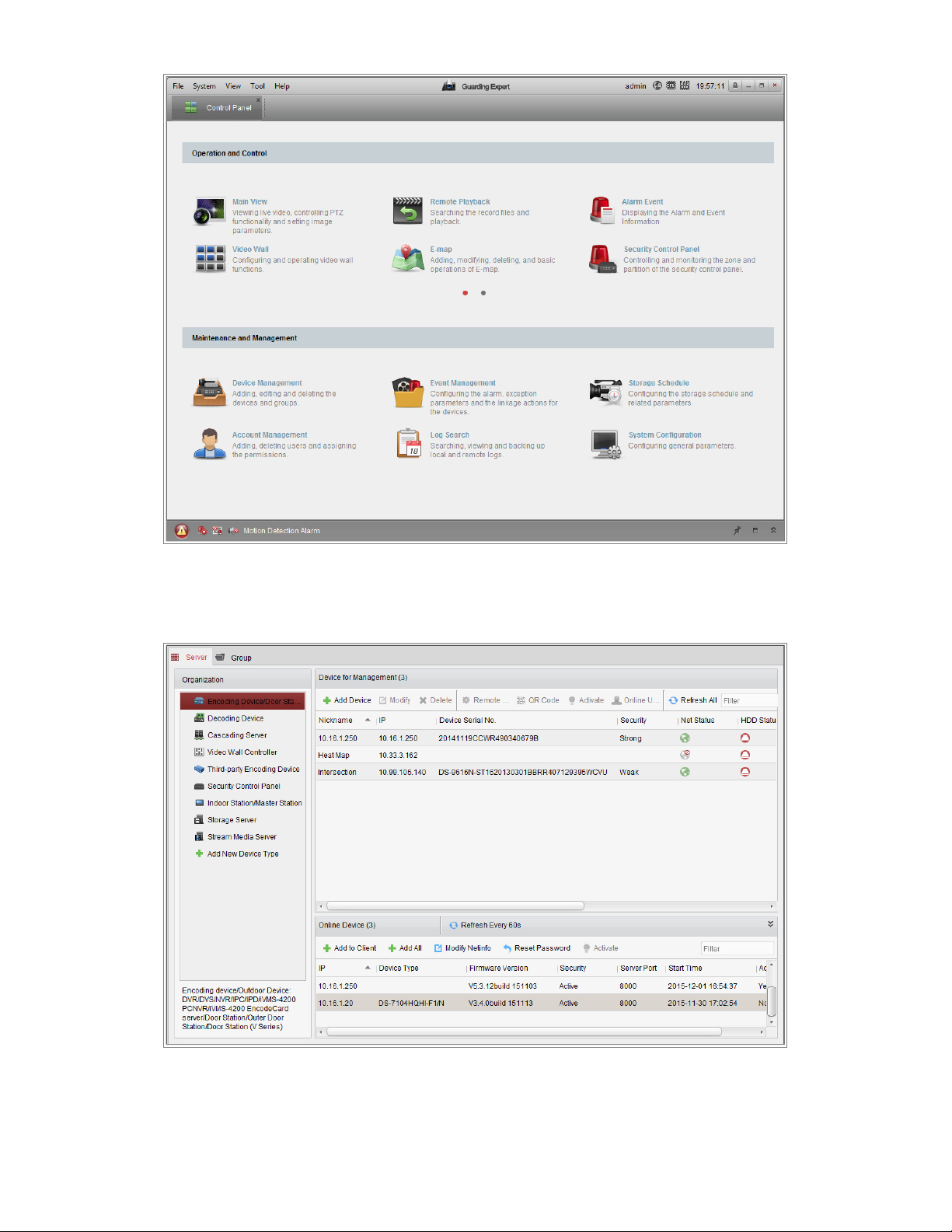
1. Run the client software and the control panel of the software pops up, as shown in the figure below.
UM DS-2CD2D21G0/M-D/NF 020319NA 12
DS-2CD2D21G0/M-D/NF User Manual
Figure 6, Control Panel
2. Click the Device Management icon to enter the Device Management interface, as shown in the figure below.
Figure 7, Device Management Interface
3. Check the device status from the device list, and select an inactive device.
UM DS-2CD2D21G0/M-D/NF 020319NA 13
DS-2CD2D21G0/M-D/NF User Manual
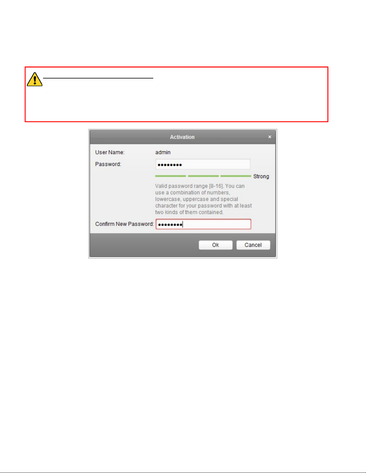
4. Click the Activate button to pop up the Activation interface.
5. Create a password, input the password in the password field, and confirm the password. A password containing a
user name is not allowed.
STRONG PASSWORD RECOMMENDED – We highly recommend that you create a strong password of
your own choosing (using a minimum of eight characters, including at least three of the following categories:
upper case letters, lower case letters, numbers, and special characters) in order to increase the security of
your product. We also recommend that you reset your password regularly. Especially in a high security
system, resetting the password monthly or weekly can better protect your product.
Figure 8, Activation Interface (Client Software)
6. Click OK button to start activation.
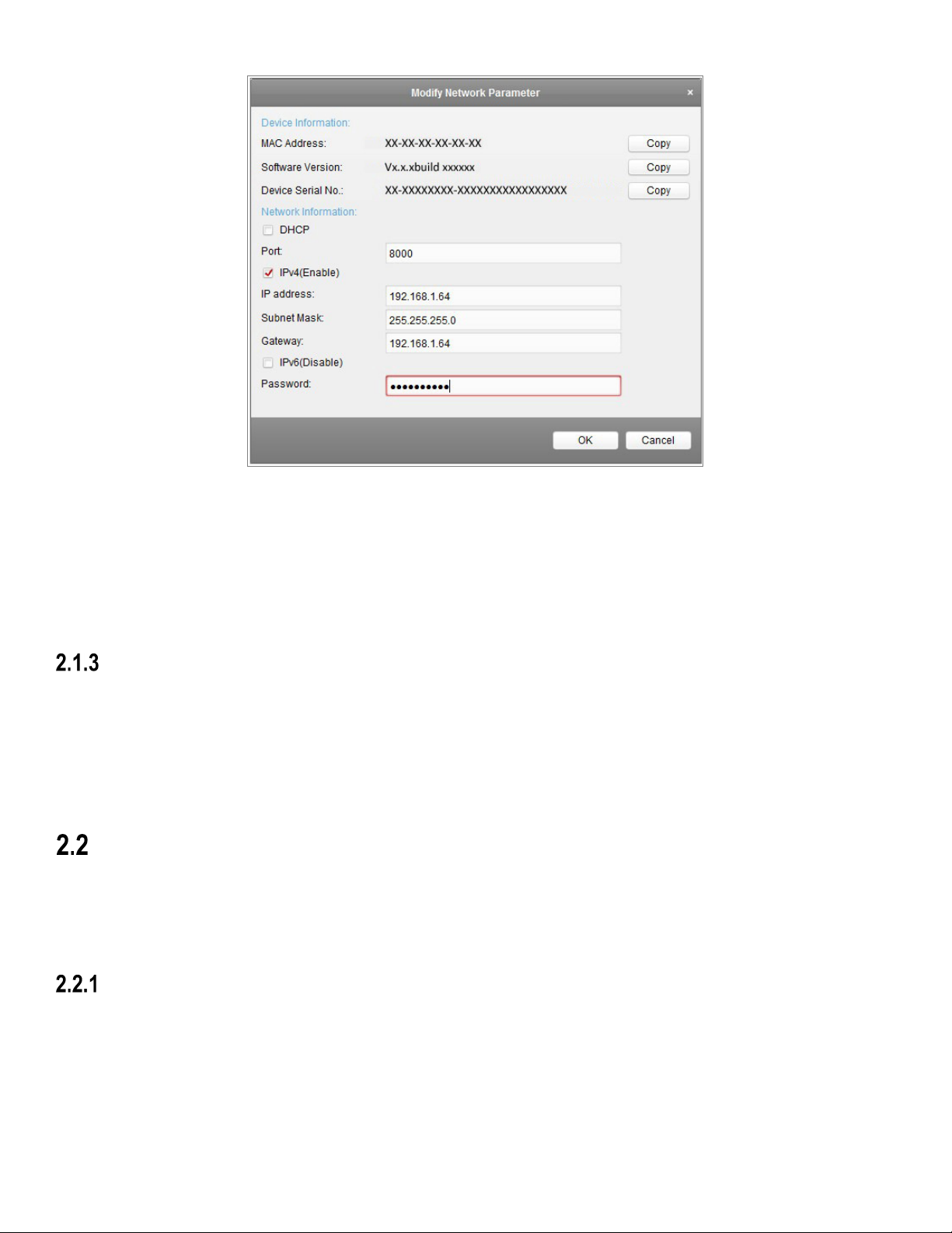
7. Click the Modify Netinfo button to pop up the Network Parameter Modification interface, as shown in the figure
below.
UM DS-2CD2D21G0/M-D/NF 020319NA 14
DS-2CD2D21G0/M-D/NF User Manual
Figure 9, Modifying the Network Parameters
8. Change the device IP address to the same subnet as your computer by either modifying the IP address manually or
checking the Enable DHCP checkbox.
9. Input the password to activate your IP address modification.
(Optional) Setting Security Question
A security question is used to reset the admin password when the admin user forgets the password.
The Admin user can follow the pop-up window to complete the security question settings during camera activation, or the
admin user can go to the User Management interface to set up the function.
Setting the Network Camera over the WAN
Purpose:
This section explains how to connect the network camera to a WAN with a static IP or a dynamic IP.
Static IP Connection
Before you start:
Please apply a static IP from an ISP (Internet Service Provider). With the static IP address, you can connect the network
camera via a router or connect it to the WAN directly.
•
Connecting the Network Camera via a Router
UM DS-2CD2D21G0/M-D/NF 020319NA 15
DS-2CD2D21G0/M-D/NF User Manual
1. Connect the network camera to the router.
2. Assign a LAN IP address, the subnet mask and the gateway. Refer to Section 2.1.2 for detailed IP address
configuration of the network camera.
3. Save the static IP in the router.
4. Set port mapping, e.g., 80, 8000, and 554 ports. The steps for port mapping vary according to the different routers.
Please call the router manufacturer for assistance with port mapping.
NOTE: Refer to Appendix 2 for detailed information about port mapping.
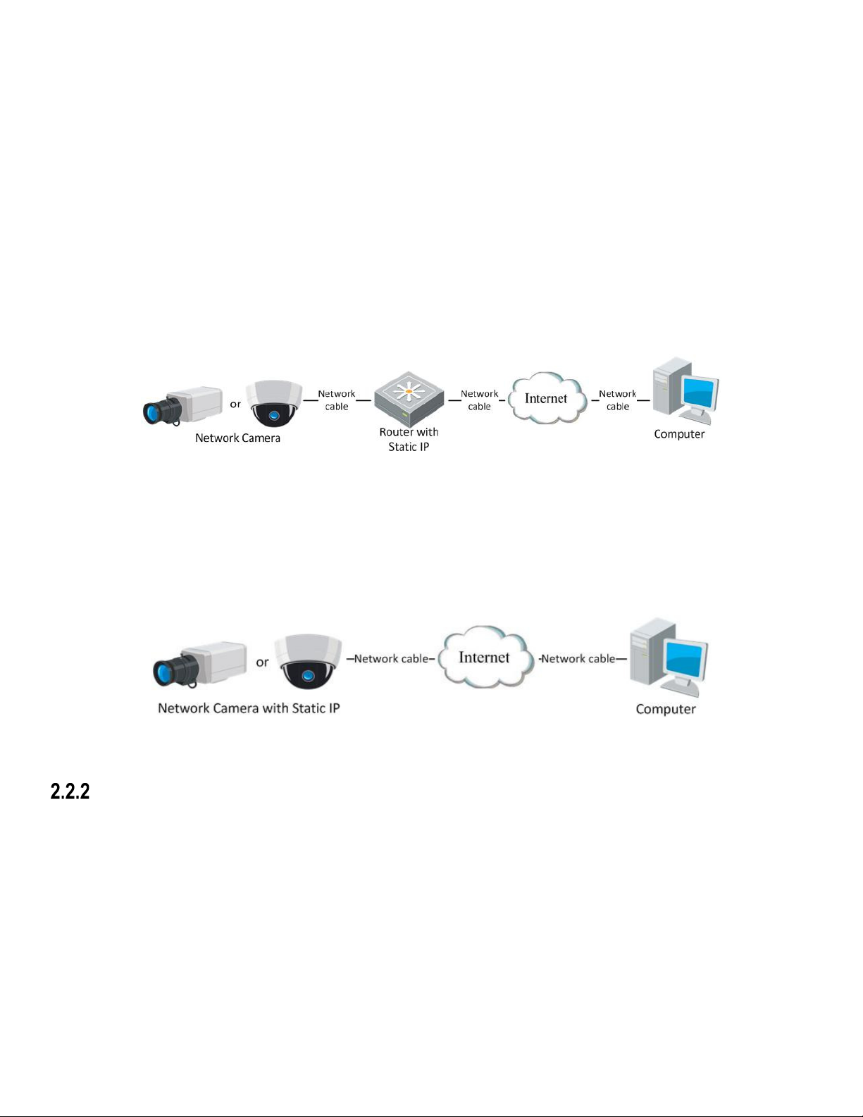
5. Visit the network camera through a Web browser or the client software over the Internet.
Figure 10, Accessing the Camera through Router with Static IP
•
Connecting the Network Camera with Static IP Directly
You can also save the static IP in the camera and directly connect it to the Internet without using a router. Refer to
Section 2.1.2 for detailed IP address configuration of the network camera.
Figure 11, Accessing the Camera with Static IP Directly
Dynamic IP Connection
Before you start:
Please apply for a dynamic IP from an ISP. With a dynamic IP address, you can connect the network camera to a modem or
a router.
•
Connecting the Network Camera via a Router
1. Connect the network camera to the router.
2. In the camera, assign a LAN IP address, the subnet mask, and the gateway. Refer to Section 2.1.2 for detailed IP
address configuration of the network camera.
UM DS-2CD2D21G0/M-D/NF 020319NA 16
DS-2CD2D21G0/M-D/NF User Manual
3. In the router, set the PPPoE user name, password and confirm the password.
4. Set port mapping. E.g., 80, 8000, and 554 ports. The steps for port mapping vary depending on different routers.
Please call the router manufacturer for assistance with port mapping.
NOTE: Refer to Appendix 2 for detailed information about port mapping.
5. Apply a domain name from a domain name provider.
6. Configure the DDNS settings in the setting interface of the router.
7. Visit the camera via the applied domain name.
•
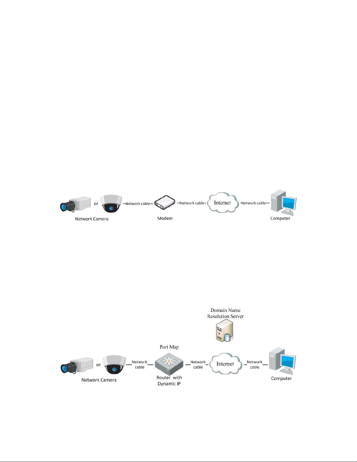
Connecting the Network Camera via a Modem
This camera supports the PPPoE auto dial-up function. The camera gets a public IP address by ADSL dial-up after the
camera is connected to a modem. You need to configure the PPPoE parameters of the network camera. Refer to
Section 7.1.3 Configuring PPPoE Settings for detailed configuration.
NOTE: The obtained IP address is dynamically assigned via PPPoE, so the IP address always changes after
rebooting the camera. To solve the inconvenience of a dynamic IP, you need to get a domain name
from the DDNS provider (e.g., DynDns.com). Please follow the steps below for normal domain name
resolution and private domain name resolution to solve the problem.
•
Normal Domain Name Resolution
Figure 12, Accessing the Camera with Dynamic IP
Figure 13, Normal Domain Name Resolution
1. Apply a domain name from a domain name provider.
UM DS-2CD2D21G0/M-D/NF 020319NA 17

DS-2CD2D21G0/M-D/NF User Manual
2. Configure the DDNS settings in the DDNS Settings interface of the network camera. Refer to Section 7.1.2
Configuring DDNS Settings for detailed configuration.
3. Visit the camera via the applied domain name.
UM DS-2CD2D21G0/M-D/NF 020319NA 18
Chapter 3 Access to the Network Camera
Accessing by Web Browsers
NOTES:
» For certain camera models, HTTPS is enabled by default and the camera creates an unsigned certificate
automatically. When you access to the camera the first time, the web browser prompts a notification about the
certificate issue.
» To cancel the notification, install a signed-certificate to the camera. For detailed operation, see 7.2.6 HTTPS
Settings.
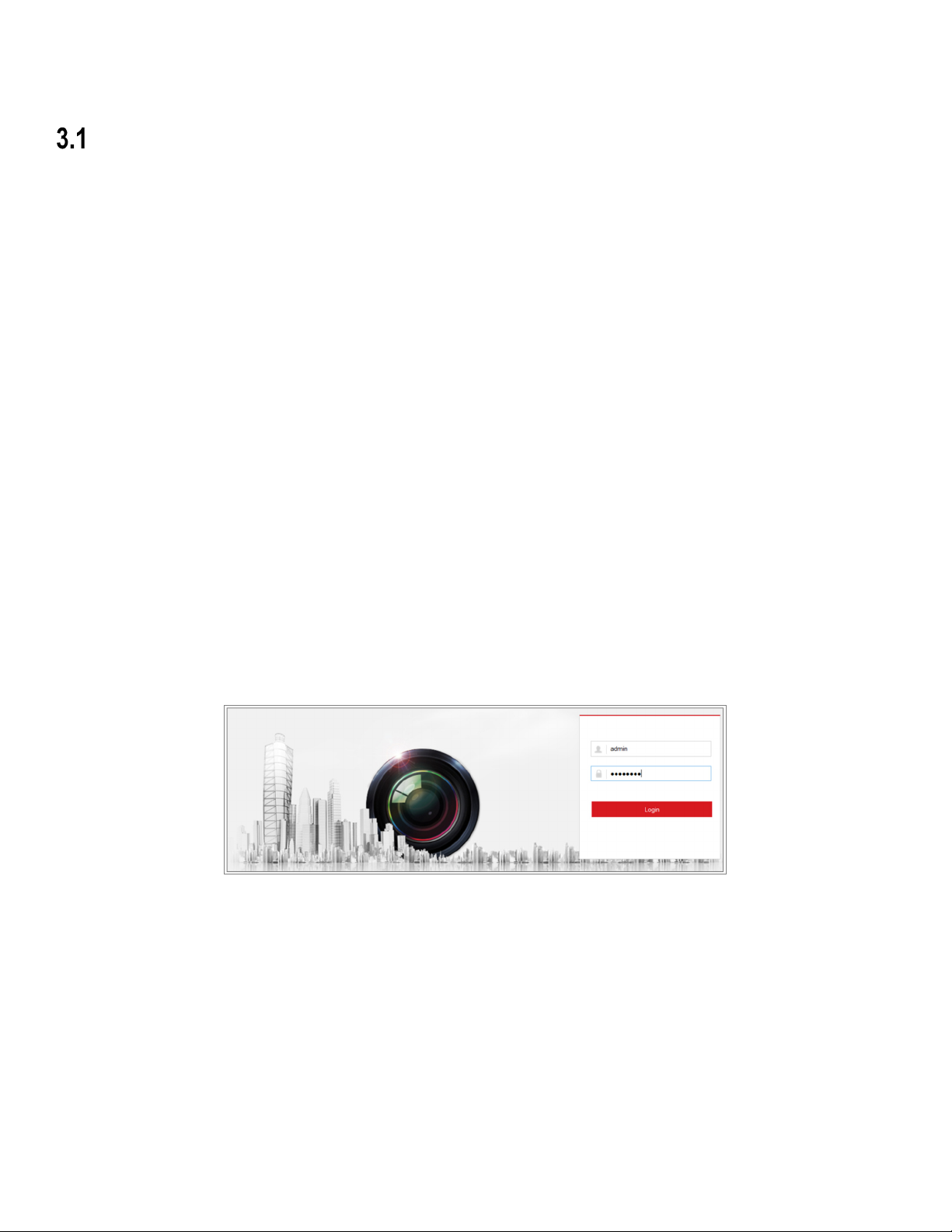
1. Open the Web browser.
2. In the browser address bar, input the IP address of the network camera, and press the Enter key to enter the login
interface.
NOTE: The default IP address is 192.168.1.64. You are recommended to change the IP address to the same
subnet as your computer.
3. Input the user name and password and click Login.
NOTE:
» The admin user should configure the device accounts and user/operator permissions properly. Delete
unnecessary accounts and user/operator permissions.
» The IP address locks if the admin user performs seven failed password attempts (five attempts for the
user/operator).
Figure 14, Login Interface
4. Click Login.
5. (Optional) Install the plug-in before viewing the live video and operating the camera. Follow the installation prompts to
install the plug-in
19
NOTE: For cameras that support plug-in free live view, if you are using Google Chrome v45 or above or
Mozilla Firefox v52 or above, plug-in installation is not required, but Picture and Playback functions are
hidden. To use these functions via a Web browser, change to their lower version, or use Internet
Explorer v8.0 or above.

DS-2CD2D21G0/M-D/NF User Manual
Accessing by Client Software
The product CD contains Hik-Connect client software. You can view live video and manage the camera with the software.
Follow the installation prompts to install the software. The control panel and live view interface of Hik-Connect client
software are shown as below.
Figure 15, Hik-Connect Control Panel
UM DS-2CD2D21G0/M-D/NF 020319NA 20

DS-2CD2D21G0/M-D/NF User Manual
Figure 16, Hik-Connect Main View
Chapter 4 Wi-Fi Settings
Purpose:
By connecting to the wireless network, you don’t need to use cables of any kind for a network connection, which is very
convenient for the actual surveillance application.
NOTE: This chapter is only for cameras with a built-in Wi-Fi module.
Configuring Wi-Fi Connection in Manage and Ad-hoc Modes
Purpose:
Two connection modes are supported. Choose a mode as desired and perform the steps to configure the Wi-Fi.
•
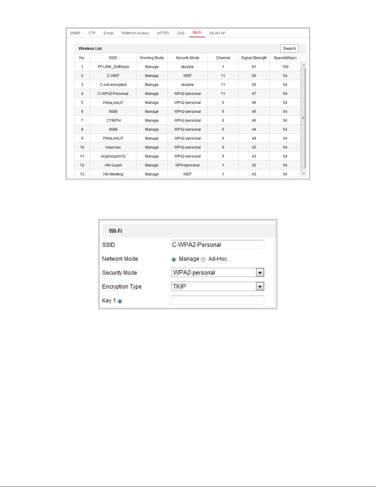
Wireless Connection in Manage Mode
1. Enter the Wi-Fi configuration interface, Configuration > Network > Advanced Settings > Wi-Fi.
2. Click Search to search the online wireless connections.
UM DS-2CD2D21G0/M-D/NF 020319NA 21
DS-2CD2D21G0/M-D/NF User Manual
Figure 17, Wi-Fi List
3. Click to choose a wireless connection on the list.
Figure 18, Wi-Fi Setting, Manage Mode
4. Check the radio button to select the Network mode as Manage, and the Security mode of the network is
automatically shown when you select the wireless network, please don’t change it manually.
NOTE: These parameters are identical to those in the router.
5. Enter the key to connect the wireless network. The key should be that of the wireless network connection you set
on the router.
•
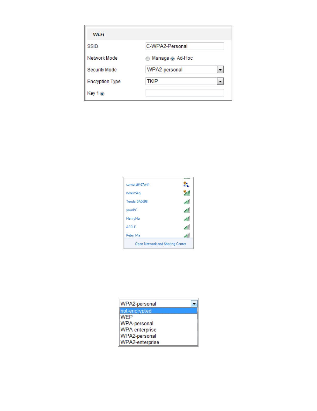
Wireless Connection in Ad-hoc Mode
If you choose the Ad-hoc mode, you don’t need to connect the wireless camera via a router. The scenario is the same
as connecting the camera and the PC directly with a network cable.
1. Choose Ad-hoc mode.
UM DS-2CD2D21G0/M-D/NF 020319NA 22
DS-2CD2D21G0/M-D/NF User Manual
Figure 19, Wi-Fi Setting, Ad-hoc
2. Customize an SSID for the camera.
3. Choose the Security Mode of the wireless connection.
4. Enable the wireless connection function for your PC.
5. On the PC side, search the network and you can see the SSID of the camera listed.
Figure 20, Ad-hoc Connection Point
6. Choose the SSID and connect.
•
Security Mode Description
Figure 21, Security Mode
You can choose the Security Mode as not-encrypted, WEP, WPA-personal, WPA-enterprise, WPA2-personal, and
WPA2-enterprise.
UM DS-2CD2D21G0/M-D/NF 020319NA 23
DS-2CD2D21G0/M-D/NF User Manual
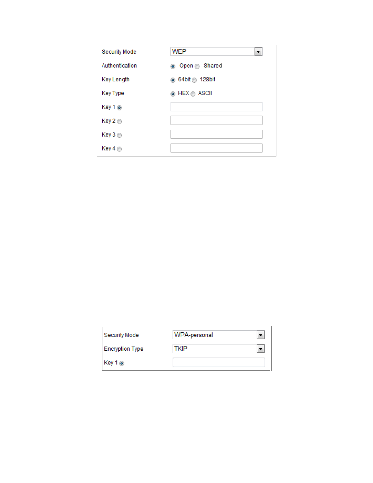
- WEP Mode
> Authentication: Select Open or Shared Key System Authentication, depending on the method used by your
access point. Not all access points have this option, in which case they probably use Open System, which is
sometimes known as SSID Authentication.
Figure 22, WEP Mode
> Key Length: This sets the length of the key used for the wireless encryption, 64 or 128 bits. The encryption key
length can sometimes be shown as 40/64 and 104/128.
> Key Type: The key types available depend on the access point being used. The following options are available:
HEX ― Allows you to manually enter the hex key
ASCII ― In this method the string must be exactly five characters for 64-bit WEP and 13 characters for 128-bit
WEP
WPA-personal and WPA2-personal Mode ― Enter the required pre-shared key for the access point, which
can be a hexadecimal number or a passphrase.
Figure 23, Security Mode, WPA-personal
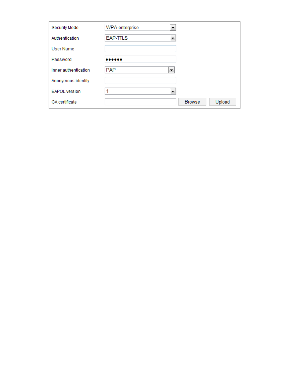
WPA-enterprise and WPA2-enterprise Mode ― Choose the type of client/server authentication being used
by the access point; EAP-TLS or EAP-PEAP.
EAP-TLS
UM DS-2CD2D21G0/M-D/NF 020319NA 24
DS-2CD2D21G0/M-D/NF User Manual
•
Identity ― Enter the user ID to present to the network.
•
Private Key Password ― Enter the password for your user ID.
Figure 24, EAP-TLS
•
EAPOL Version ― Select the version used (1 or 2) in your access point.
•
CA Certificates ― Upload a CA certificate to present to the access point for authentication.
UM DS-2CD2D21G0/M-D/NF 020319NA 25
DS-2CD2D21G0/M-D/NF User Manual
EAP-PEAP:
•
User Name ― Enter the user name to present to the network
•
Password ― Enter the password of the network
•
PEAP Version ― Select the PEAP version used at the access point.
•
Label ― Select the label used by the access point.
•
EAPOL Version ― Select version (1 or 2) depending on the version used at the access point
•
CA Certificates ― Upload a CA certificate to present to the access point for authentication
CAUTION!
For your privacy and to better protect your system against security risks, we strongly recommend the use of strong
passwords for all functions and network devices. The password should be something of your own choosing (using a
minimum of eight characters, including at least three of the following categories: upper case letters, lower case letters,
numbers and special characters) in order to increase the security of your product.
Proper configuration of all passwords and other security settings is the responsibility of the installer and/or end-user.
Easy Wi-Fi Connection with WPS function
Purpose:
The setting of the wireless network connection is never easy. To avoid the complex setting of the wireless connection you
can enable the WPS function.
WPS (Wi-Fi Protected Setup) refers to the easy configuration of the encrypted connection between the device and the
wireless router. The WPS makes it easy to add new devices to an existing network without entering long passphrases.
There are two modes of the WPS connection, the PBC mode and the PIN mode.
NOTE: If you enable the WPS function, you do not need to configure the parameters such as the encryption
type, and you don’t need to know the key of the wireless connection.
UM DS-2CD2D21G0/M-D/NF 020319NA 26
DS-2CD2D21G0/M-D/NF User Manual
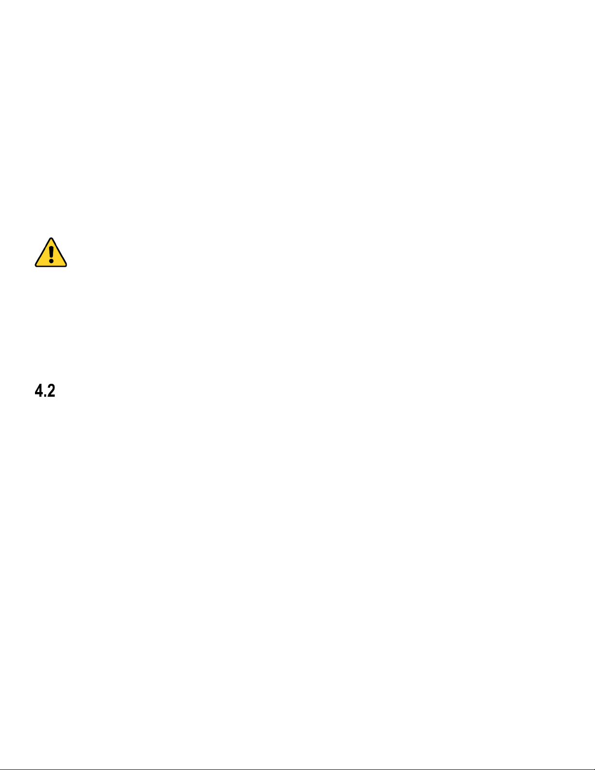
Figure 25, Wi-Fi Settings, WPS
•
PBC Mode
PBC refers to the Push-Button-Configuration, in which the user simply has to push a button, either an actual or virtual
one (as the button on the configuration interface of the IE browser), on both the Access Point (and a
registrar of the network) and the new wireless client device.
1. Check the Enable WPS checkbox to enable WPS.
2. Choose the connection mode as PBC.
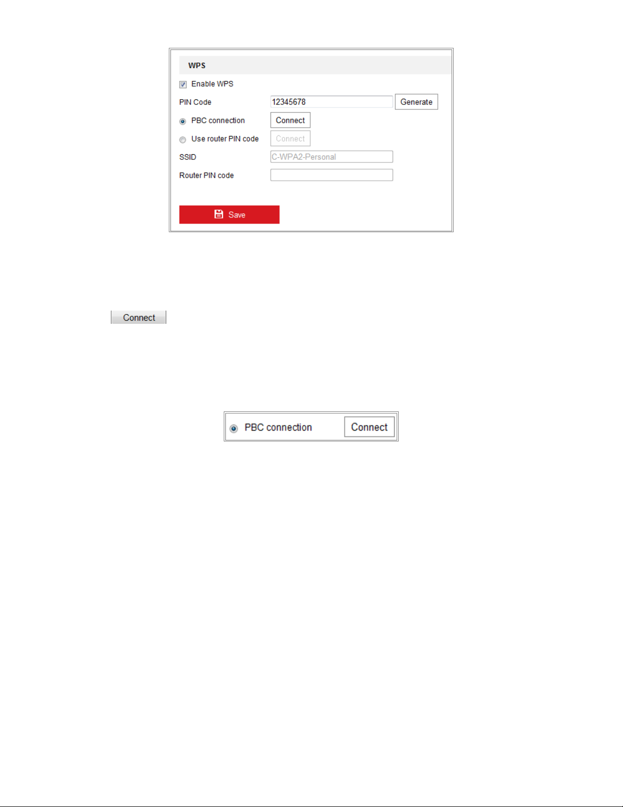
Figure 26, PBC Connection
NOTE: Support of this mode is mandatory for both the Access Points and the connecting devices.
3. Check on the Wi-Fi router to see if there is a WPS button. If yes, push the button and the indicator near the button
will start flashing, which means the WPS function of the router is enabled. For detailed operation, please see the
user guide of the router.
4. Push the WPS button to enable the function on the camera. If there is no WPS button on the camera, you can also
click the virtual button to enable the PBC function on the Web interface.
5. Click Connect button. When PBC mode is both enabled in the router and the camera, the camera and the wireless
network connect automatically.
•
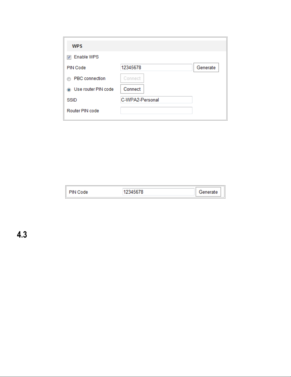
PIN Mode
The PIN mode requires a Personal Identification Number (PIN) to be read from either a sticker or the display on the new
wireless device. This PIN must then be entered to connect the network, usually the Access Point of the network.
1. Choose a wireless connection on the list, and the SSID is loaded automatically.
UM DS-2CD2D21G0/M-D/NF 020319NA 27
DS-2CD2D21G0/M-D/NF User Manual
2. Choose Use Route PIN code.
Figure 27, Use PIN Code
If the PIN code is generated from the router side, enter the PIN code you get from the router side in the Router PIN
code field.
3. Click Connect or generate the PIN code on the camera side. The expired time for the PIN code is 120 seconds.
A. Click Generate.
Figure 28, PIN Code
B. Enter the code to the router. In the example, enter 48167581 into the router.
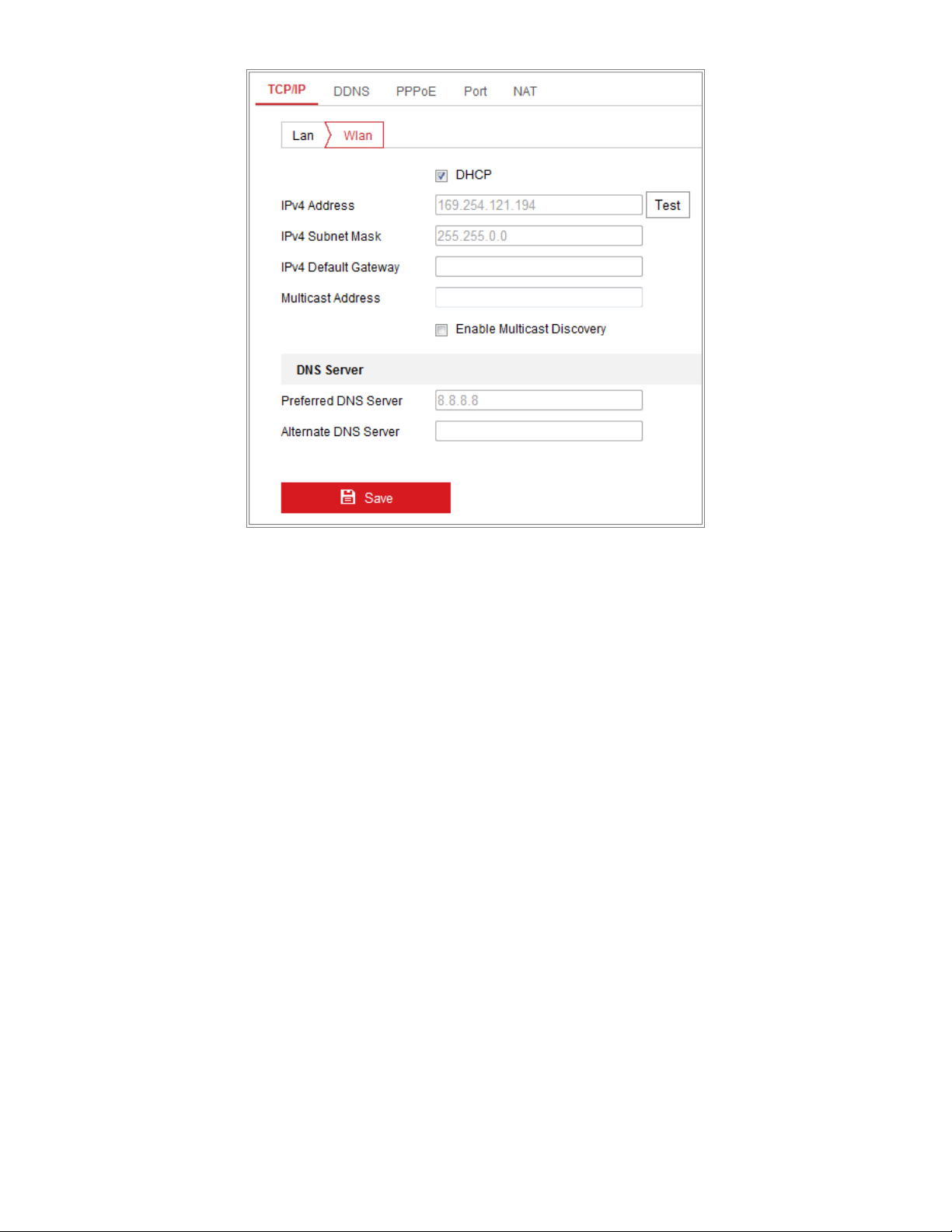
IP Property Settings for Wireless Network Connection
The default IP address of a wireless network interface controller is 192.168.1.64. When you connect the wireless network
you can change the default IP.
1. Enter the TCP/IP configuration interface, Configuration > Network > Basic Settings > TCP/IP.
2. Select the Wlan tab.
UM DS-2CD2D21G0/M-D/NF 020319NA 28
DS-2CD2D21G0/M-D/NF User Manual
Figure 29, Setting WLAN Parameters
3. Customize the IPv4 address, the IPv4 Subnet Mask, and the Default Gateway.
The setting procedure is the same as that of the LAN.
To be assigned the IP address, check the Enable DHCP checkbox.
UM DS-2CD2D21G0/M-D/NF 020319NA 29
 Loading...