

Page 1

Henny Penny
Rotisserie
Model SCR-6/8
OPERATOR’S MANUAL
Page 2

Page 3

SCR-6/8
LIMITED WARRANTY FOR HENNY PENNY APPLIANCES
Subject to the following conditions, Henny Penny Corporation makes the following limited warranties to the
original purchaser only for Henny Penny appliances and replacement parts:
NEW EQUIPMENT: Any part of a new appliance, except lamps and fuses, which proves to be defective
in material or workmanship within two (2) years from date of original installation, will be repaired or replaced
without charge F.O.B. factory, Eaton, Ohio, or F.O.B. authorized distributor. To validate this warranty, the
registration card for the appliance must be mailed to Henny Penny within ten (10) days after installation.
REPLACEMENT PARTS: Any appliance replacement part, except lamps and fuses, which proves to be
defective in material or workmanship within ninety (90) days from date of original installation will be repaired
or replaced without charge F.O.B. factory, Eaton, Ohio, or F.O.B. authorized distributor.
The warranty for new equipment and replacement parts covers only the repair or replacement of the defective
part and does not include any labor charges for the removal and installation of any parts, travel, or other expenses
incidental to the repair or replacement of a part.
EXTENDED FRYPOT WARRANTY: Henny Penny will replace any frypot that fails due to manufacturing or
workmanship issues for a period of up to seven (7) years from date of manufacture. This warranty shall not cover
any frypot that fails due to any misuse or abuse, such as heating of the frypot without shortening.
0 TO 3 YEARS: During this time, any frypot that fails due to manufacturing or workmanship issues will be replaced at no charge for parts, labor, or freight. Henny Penny will either install a new
frypot at no cost or provide a new or reconditioned replacement fryer at no cost.
3 TO 7 YEARS: During this time, any frypot that fails due to manufacturing or workmanship issues will be replaced at no charge for the frypot only . Any freight charges and labor costs to install
the new frypot as well as the cost of any other parts replaced, such as insulation, thermal sensors,
high limits, fittings, and hardware, will be the responsibility of the owner.
Any claim must be presented to either Henny Penny or the distributor from whom the appliance was purchased.
No allowance will be granted for repairs made by anyone else without Henny Penny’s written consent. If damage
occurs during shipping, notify the sender at once so that a claim may be filed.
THE ABOVE LIMITED WARRANTY SETS FORTH THE SOLE REMEDY AGAINST HENNY PENNY
FOR ANY BREACH OF WARRANTY OR OTHER TERM. BUYER AGREES THAT NO OTHER REMEDY
(INCLUDING CLAIMS FOR ANY INCIDENTAL OR CONSEQUENTIAL DAMAGES) SHALL BE AVAILABLE.
The above limited warranty does not apply (a) to damage resulting from accident, alteration, misuse, or abuse;
(b) if the equipment’s serial number is removed or defaced; or (c) for lamps and fuses. THE ABOVE LIMITED
WARRANTY IS EXPRESSLY IN LIEU OF ALL OTHER WARRANTIES, EXPRESS OR IMPLIED, INCLUDING MERCHANTABILITY AND FITNESS, AND ALL OTHER WARRANTIES ARE EXCLUDED. HENNY
PENNY NEITHER ASSUMES NOR AUTHORIZES ANY PERSON TO ASSUME FOR IT ANY OTHER OBLIGATION OR LIABILITY.
FM05-014-D
Revised 04-19-06
Page 4

Page 5

TABLE OF CONTENTS
Section Page
Section 1. INTRODUCTION.................................................................................................... 1-1
1-1. Henny Penny Rotisserie ................................................................................1-1
1-2. Features .........................................................................................................1-1
1-3. Assistance...................................................................................................... 1-1
1-4. Safety ............................................................................................................. 1-2
1-5. Proper Care ...................................................................................................1-2
Section 2. INSTALLATION...................................................................................................... 2-1
2-1. Introduction .................................................................................................... 2-1
2-2. Unpacking ...................................................................................................... 2-1
2-3. Location .........................................................................................................2-2
2-4. Stacking Instructions ......................................................................................2-2
2-5. Stacking Instructions for Single Power Cord Units .......................................2-4
2-6 Stacking and Outboard Caster Installation Instructions ................................. 2-5
2-7. Leveling of Unit .............................................................................................2-7
2-8. Electrical Requirements ................................................................................. 2-7
Section 3. OPERATION ............................................................................................................ 3-1
3-1. Introduction ....................................................................................................3-1
3-2. Controls and Switches ................................................................................... 3-1
3-3. Installation of Discs, Rods, and Spits............................................................. 3-5
3-4. Procedure for Angled Spits............................................................................ 3-6
3-5. Procedure for Double Spits (Optional) .......................................................... 3-6
3-6. Use of Optional Accessories .........................................................................3-7
3-7. Operation Mode............................................................................................. 3-7
3-8. Preheat Control..............................................................................................3-8
3-9. Cooking Control ............................................................................................. 3-8
3-10. Door Sensor................................................................................................... 3-8
3-11 . Hold Control .................................................................................................. 3-8
3-12. Cleaning Procedures...................................................................................... 3-9
3-13. Halogen Lamp Replacement ......................................................................... 3-10
SCR-6/8
Section 4. PROGRAMMING .................................................................................................... 4-1
4-1. Introduction .................................................................................................... 4-1
4-2. Programming for Cook and Hold ................................................................... 4-1
4-3. Special Program Mode (Level 2)...................................................................4-4
4-4. Tech Mode ..................................................................................................... 4-6
Section 5. COOKING PROCEDURES ....................................................................................5-1
5-1. Program Cook Parameters ............................................................................ 5-1
5-2. Loading the Rotisserie ...................................................................................5-1
5-3. Removing Spits and Product from the Rotisserie ..........................................5-1
5-4. Seasonings and Barbecue Sauce ................................................................... 5-2
5-5. Basic Rules of Safe Food Preparation........................................................... 5-2
5-6. Minimum Temperature Requirements for Hot and Cold Food Storage ......... 5-3
5-7. Testing for Doneness .....................................................................................5-3
5-8. Basic Cooking Procedures............................................................................. 5-4
5-9. Cooking Guidelines......................................................................................... 5-5
105 i
Page 6

TABLE OF CONTENTS
Section Page
Section 6. TROUBLESHOOTING ...........................................................................................6-1
6-1. Troubleshooting Guide.................................................................................... 6-1
6-2. Error Codes.................................................................................................... 6-2
GLOSSARY.............................................................................................................. G-1
Distributors List - Domestic and International
SCR-6/8
ii 503
Page 7

SECTION 1. INTRODUCTION
1-1. HENNY PENNY The Henny Penny Rotisserie, SCR-6 or 8 , combines
ROTISSERIE rotating convection heat with rotating discs so that food browns
more evenly and cooks faster . It can also be used as a display unit
for displaying product while in the cooking or holding mode.
As of August 16, 2005, the W aste Electrical and Electronic
Equipment directive went into effect for the European Union.
Our products have been evaluated to the WEEE directive. W e
have also reviewed our products to determine if they comply
with the Restriction of Hazardous Substances directive (RoHS)
and have redesigned our products as needed in order to
comply . T o continue compliance with these directives, this unit
must not be disposed as unsorted municipal waste. For proper
disposal, please contact your nearest Henny Penny distributo
SCR-6/8
1-2. FEA TURES
y Distinctive compact design
y Preselected automatic controls
y Integrated solid state controls
y Combination hot air convection and infrared cooking
y Rotating disc movement
y LED readout control panel
y T empered glass doors
y Removable drain pan
y Removable rotor disc
y Stainless steel construction
y Removable vent panels for easy cleaning
1-3. ASSISTANCE Should you require assistance, just call your local independent
distributor (refer to the distributor list in the rear of this
manual).
In addition, feel free to contact our corporate headquarters in
Eaton, Ohio by dialing our toll free number 1-800-417-8405
or 1-937-456-8405, or go to Henny Penny online at
www .hennypenny.com.
406 1-1
Page 8

SCR-6/8
1-4. SAFETY T o ensure safe operation of the Henny Penny rotisserie, the proper
procedures for installation, operation, and maintenance should be
followed and properly understood. Where information is of
particular importance or is safety related, the words WARNING ,
CAUTION, and NOTE are used. Their usage is as follows:
SAFETY ALER T SYMBOL is used with DANGER,
W ARNING, or CAUTION which indicates a personal injury
type hazard.
NOTICE is used to highlight especially important
information.
CAUTION used without the safety alert symbol indicates
a potentially hazardous situation which, if not avoided,
may result in property damage.
CAUTION used with the safety alert symbol indicates
a potentially hazardous situation which, if not
avoided, may result in minor or moderate injury.
W ARNING indicates a potentially hazardous situation
which, if not avoided, could result in death or serious
injury.
1-5. PROPER CARE As with any of our equipment, the rotisserie does require care and
maintenance, which are discussed in this manual. The careful use
of the recommended procedures, coupled with the regular preventive maintenance, will result in few repairs to the equipment.
1-2 203
Page 9

SECTION 2. INSTALLATION
2-1. INTRODUCTION This section provides the installation instructions for the Henny
Penny Rotisserie.
Installation of this unit should be performed by a qualified
service technician. The installation of this unit must conform to
all local, state, and federal codes.
Do not puncture the rotisserie with any objects such as
drills or screws as electrical shock, or component
damage could result.
SCR-6/8
2-2. UNP ACKING The Henny Penny Rotisserie has been tested, inspected, and
expertly packed to ensure arrival at its destination in the best
possible condition. The unit is packed inside a heavy
cardboard carton with sufficient padding to withstand normal
shipping treatment.
Any shipping damages should be noted in the presence of the
delivery agent and signed prior to his or her departure.
T o remove the Henny Penny Rotisserie from the carton you
should:
1. Carefully cut banding straps.
2. Remove packing from around the unit.
3. Lift carton from unit.
4. Remove brackets securing unit to skid.
5. Remove unit from skid.
6. Y our rotisserie is now ready for setup.
303 2-1
Page 10

SCR-6/8
2-3. LOCATION The proper location of the unit is very important for operation and
convenience. Choose a location which will provide easy loading and
unloading without interfering with the final assembly of food orders.
The SCR-6/8 rotisseries must be 2 inches from any rear wall.
No minimum spacing is required for the sides of the units. After
the Henny Penny Rotisserie has been placed on a table, run a
bead of silicone (silicone or equivalent sealant must be a NSF
listed material) around the perimeter of the unit sealing it to the
table top. You are now ready to make the electrical connection.
SCR-12 and SCR-16 both require 3 inches from any rear wall.
Again, no spacing is required for the sides of the units.
SCR-8’s with customer side mirrored glass require 4 inches from
any rear wall. Again, no spacing is required for the sides of the
units.
2-4. ST ACKING
INSTRUCTIONS
The SCR series rotisserie is a commercial appliance,
and many surfaces could be hot. To prevent burns, it is
recommended that the unit be located in an area that
cannot be accessed by the public.
A stacking kit must be used to stack rotisseries, or to stack a
rotisserie on a display . This kit ensures 3 inches clearance
from a rear wall. The part numbers of the stacking kits are
02664, for use on the SCR-6 and SCD-6, and 02665 is
used on the SCR-8 and SCD-8.
See page 2-4 for single power cord installations.
1. Lay unit on its side and bolt locking casters or legs, to
the control side of unit.
2. Using the bolts provided for the non-locking casters, or
legs, bolt both the stacking spacer (provided in the kit)
and the non-locking caster, or legs, to the front side of the
unit. The stacking spacer should extend out the front of
the unit about three inches.
3. Carefully lift the rotisserie and place it on top of the
display , or bottom rotisserie, with the controls on the
same side.
2-2 303
Page 11

2-4. ST ACKING
INSTRUCTIONS
(Continued)
Figure 1
SCR-6/8
T ake care when moving the unit to pr event personal
injury. The SCR-8 weighs approximately 500 lbs.
(230 kg) and the SCR-6 weighs 380 lbs. (172 kg).
4. Remove the three side panel screws from the top unit
and remove the three top side panel side screws from
the bottom unit.
5. Mount the stacking brackets to each side of the units, as
shown in Figure 1, using the screws removed in step 4.
6. Unit is now ready for use.
For units being installed in Canada, for Price Costco,
proceed with the following steps:
7. Remove the black plug button from the top of the upper unit.
8. Remove the screws from the channel assembly and take
the top two parts apart.
9. Remove the screws along the corners of both top and
bottom units.
10. Mount one side of the channel to the units, using the
screws previously removed in step 9. See Figure 2.
11. Route the power cord up through the mounted channel
and attach the cover to the channel, using the screws
previously removed in step 8. See Figure 2.
12. Unit is now ready for use.
Figure 2
203 2-3
Page 12
SCR-6/8
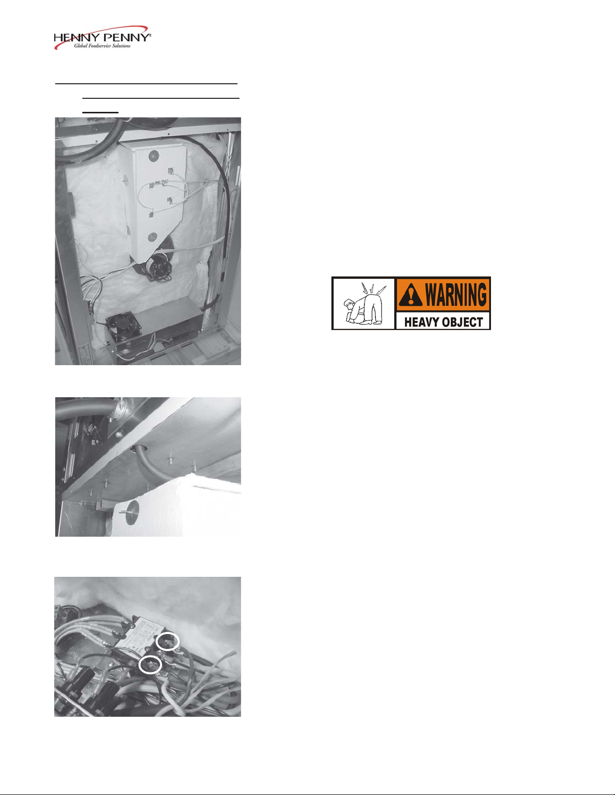
2-5. ST ACKING INSTRUCTIONS
FOR SINGLE POWER CORD
UNITS
Figure 1
1. Lay unit on its side and bolt locking casters or legs, to
the control side of unit.
2. Using the bolts provided for the non-locking casters, or
legs, bolt both the stacking spacer (provided in the kit)
and the non-locking caster, or legs, to the front side of the
unit. The stacking spacer should extend out the front of
the unit about three inches.
3. Carefully lift the rotisserie and place it on top of the
display , or bottom rotisserie, with the controls on the
same side.
T ake care when moving the unit to pr event personal
injury. The SCR-8 weighs approximately 500 lbs.
(230 kg) and the SCR-6 weighs 380 lbs. (172 kg).
Figure 2
4. Remove the control side, side panels from both units.
5. Route the power cord inside of the SCD as shown in
Figure 1.
6. Thread the SCD power cord up through both units, using the
hole in the center, top of the SCD. See figure 2.
7. Using a flat-head screwdriver, mount the power cord wires to
the contactor terminals shown in figure 3.
8. Replace side panels, mounting the stacking brackets to each
side of the units, as shown in Figure 1 (page 2-3), using the
screws removed in step 4.
9. Unit is now ready for use.
Figure 3
2-4 1104
Page 13
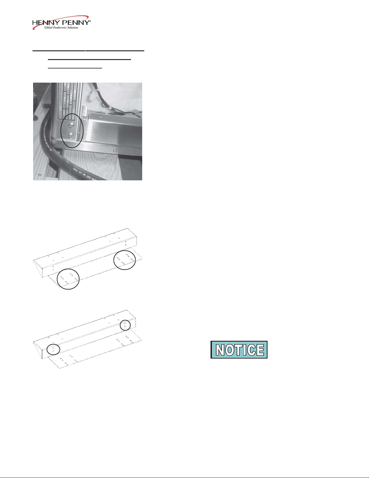
2-6. ST ACKING AND OUTBOARD
CASTER INST ALLA TION
INSTRUCTIONS
Figure 1
SCR-6/8
1. Using a Phillip’s head screwdriver, remove the 8, 1/4-20 x
1 in. screws in the corners of the unit. Figure 1.
2. Remove all contents from inside of unit. Carefully lay the
unit over onto the customer side of the unit. Be sure to
protect the glass door from damage, such as placing packing material between unit and a wood pallet. (If the door
on the customer side has a handle on it, allow the door
handle to hang over the edge to the wood pallet.)
Figure 2
Figure 3
3. Using a 7/16 in. wrench or socket, remove the bolts, washers and lockwashers from the bottom of the unit.
4. Using the hardware removed in step 3, and the caster
mounting holes in the bottom of the unit, fasten the outboard caster brackets to the bottom of the unit, along
with the stacking spacer, if present. (The stacking spacer
should be on the customer side of the unit.) Then, using 8,
1/4-20 x 1 in. screws (from step 1) fasten the caster brackets to both sides of the unit. Figures 2 & 3.
Th e brackets can be used on either side, thus the 16
mounting holes in the bracket, shown in Figure 2.
105 2-5
Page 14

2-6. ST ACKING AND OUTBOARD
CASTER INST ALLATION
INSTRUCTIONS (Continued)
Figure 4
SCR-6/8
5. Attach casters to the caster bracket (Figure 4), mounting
the two locking swivel casters to the control side of the
unit and the non-locking casters to the customer side. Use
the 5/16 inch hex head bolts, 5/16 inch locking washers,
5/16 inch nuts and 5/16 inch flat washers (use 2 flat
washers per bolt; one on the bottom side of caster bracket
and one on the top-side) which are provided. Completed
installation shown in Figure 5.
6. Set the unit onto its casters and carefully lift the rotisserie
and place it on top of the display , or bottom rotisserie, with
the controls on the same side.
Figure 5
Figure 6
T ake care when moving the unit to pr event personal
injury. The SCR-8 weighs approximately 500 lbs.
(230 kg) and the SCR-6 weighs 380 lbs. (172 kg).
7. Remove the three side panel screws from the top unit
and remove the three top side panel side screws from the
bottom unit.
8. Mount the stacking brackets to each side of the units, as
shown in Figure 6, using the screws removed in step 7.
9. Unit is now ready for use.
2-6 105
Page 15

SCR-6/8
2-7. LEVELING OF UNIT For proper operation, the rotisserie should be level from side to side
and front to back. This will ensure proper door operation.
2-8. ELECTRICAL The Henny Penny Rotisserie is available from the factory , wired
REQUIREMENTS for 208 or 240 volt, 220-380 volt, 240-415 volt, 230-400
volt, 1 or 3 phase, 50/60 hertz service.
This unit must be adequately and safely grounded.
Refer to local electrical codes for correct grounding
procedures. If unit is not adequately grounded, electrical shock could result.
Model Volts Phase Amps Watts Wire
No.
SCR-8 208 3 33.6 11,100 3+G
208 1 50.5 11,100 2+G
240 3 29.1 11,100 3+G
240 1 46 11,100 2+G
400 3 19.3 11,000 4+G
SCR-6 208 3 22.8 6800 3+G
208 1 32.5 6800 2+G
240 3 19.7 6800 3+G
240 1 28.3 6800 2+G
400 3 13.5 6800 4+G
303 2-7
Page 16

Page 17

SCR-6/8
SECTION 3. OPERATION
3-1. INTRODUCTION The Henny Penny Rotisserie is computer controlled. The computer
control regulates the cabinet temperatures and provides timing and
program functions of the rotisserie.
3-2. CONTROLS AND SWITCHES (Refer to Figures 3-1 and 3-2)
Item Description Function
1 Power Switch This two position rocker switch controls power to the rotisserie
and the control panel
2 Rotation Switch Pressed to bypass the computer control and
on; a rotation switch may be located on both and the operator
side and customer side
3 Meat Probe After plugging the meat probe into the receptacle, the meat probe
can then be inserted into the product and the product temperature
is displayed
4 Preheating LED Turns on during a Preheating Mode
5 Program LED Flashes during a Program Mode
turns the rotor motor
6 Product LED Located above each product button; it turns on when a product is
selected and during programming; the LED flashes during Cook
and Hold Cycles
7 Product Up and Down T en product selections, labeled M through P9; selected by
Buttons pressing the Up and Down buttons
8 Cook or Hold LED Turns on during a cook cycle and during the Hold Cycle
9 Program Button Pressed to access the Program and Special Program Modes.
10 Menu Board Displays the product names; the menu items can be changed
1 1 Digital Displays Three digital LED displays which show
and messages associated with the
12 Ready LED Turns on during preheat when the temperature nears the pro-
grammed set point temperature; it turns off during a
203 3-1
the temperature, time,
control operation
Cook Cycle
Page 18

3-2. CONTROLS AND SWITCHES (Refer to Figures 3-1 and 3-2)
(Continued)
.
Item Description Function
13 Start Button Pressed to begin the unit preheating or begins a Cook Cycle
14 Stop Button Pressed to end a Cook or Hold Cycle
15 Alarm Button Pressed to view or change the alarm settings; the settings can
be changed at any time
16 Temperature Pressed to view the current oven temperature
Button
17 Set Temperature Up Pressed to change the temperature setpoint
and Down Buttons
SCR-6/8
18 Set Time Up and Pressed to change the time settings
Down Buttons
19 Time LEDs Illuminates when changing the time
20 T emperature LEDs Illuminates when changing the temperature
3-2 203
Page 19

SCR-6/8
3
Figure 3-1
1
2
203 3-3
Page 20

12
4 8
11
13 14
SCR-6/8
11
19
15 18
11
20
16
17
6
7
10
9
5
Figure 3-2
3-4 401
Page 21

3-3. INST ALLATION OF DISCS,
RODS, AND SPITS
SCR-6/8
1. Fit discs up to appropriate disc support on each side
of unit.
2. Place each end of the rod assembly into the hubs on each disc.
3. Slide the collars onto each hub of discs.
4. Slide retention rings over hubs and into slot on rod.
5. Slip angled spits onto discs, with the “V” of the angled spits
towards the rod.
Fit the spit with the “V” towards the rod. Reversing the spit will
result in spits tilted at an angle.
When removing the rod assembly, make sure indicator is
pointed up towards top of unit. If it is pointed down, the
rod assembly will fall.
203 3-5
Page 22

SCR-6/8
3-4. PROCEDURE FOR The angled spits are the standard accessory for the Henny Penny
ANGLED SPITS rotisseries. Some of the advantages of the angled spits, compared
to the double spits, are the ease and speed in which whole chickens
can be placed on the spits. Also, cooking on spits compared to
baskets and pans is superior as the meat cooks more uniformly and
is basted by itself as it rotates. It is important to place meat on the
spit evenly for even cooking results.
Place the chicken on its back. Cut a small slit in the extra skin at the
tail end of the chicken. Place one, then the other leg through the slit,
so the legs are in a crossed fashion. Fold the wings up behind the
neck.
Figure 3-3
3-5. PROCEDURE FOR DOUBLE The double spits are optional accessories. Some of the advantages
SPITS (OPTIONAL) of cooking on spits compared to baskets or pans are that the meat
Hold the spit with the opening of the “V” shape facing upwards
and the angle of the “V” towards the table. Slide the spit
lengthwise through the body cavity of the chicken, tail cavity
first, with the breast up (see Figure 3-3).
cooks more uniformly and is basted by itself as it rotates. It is
important to place meat on the spit evenly for even cooking results.
Place chicken and small poultry on spits in a vertical position
maximum capacity (see Figure 3-4). Place chicken on its back.
Gently push legs and thighs toward the back. This gives the
more plump appearance and positions the drumsticks
insertion of the spit. Run one point of the spit
the height of the wings. Run the other
of the drumstick and lower body .
side of the chicken. W ings
behind the neck.
can either be pinned by the spit or folded
point through the large part
Push the spit through to the other
through the chest at
better for
for
chest a
Figure 3-4
If turkey or large poultry is cooked, it may be necessary to
them horizontally on spits so they do not touch the top
or interfere with adjacent spits. In this case, run
through the breast and thighs.
Whole roasts - beef, lamb, pork and ham, should be centered
spits evenly . Most roasts will have to be placed on spits
due to their size and shape. However, if small roasts
they can be placed vertically on spits, provided
the top of the oven or interfere with adjacent spits.
3-6 203
the spits lengthwise
they do not touch
place
of the oven
on the
lengthwise
are cooked,
Page 23

SCR-6/8
3-5. PROCEDURE FOR DOUBLE Pork ribs - spare or baby racks should be weaved on the spits
SPITS (Continued) like an accordion. Both tines of the spits should pierce the slab.
Best results are obtained if poultry or roasts are not crowded
together. Leave adequate space between products for best
browning.
3-6. USE OF OPTIONAL Baskets are available as an option for food products too small or
ACCESSORIES impractical to put on spits.
Meatloaf, fish, stuffed bell peppers, and frozen pastries are examples
of products that can be baked in the baskets.
If baskets are used instead of spits to bake whole chicken or roasts,
keep in mind these products will require more time to cook and the
browning will not be as uniform.
Coated accessories are available. For more information, contact
your local independent Henny Penny distributor.
3-7. OPERA TION MODE The control has ten product Cook Cycles which may be pro-
grammed for specific products. Each cycle may consist of up to four
cook steps and a hold parameter.
1. Press the UP or DOWN button, under PRODUCT SELEC-
TION, to select the desired product. Then press the ST AR T
button and the unit will begin to preheat to the temperature
appropriate for that product.
The Manual Mode is not programmed and a cook time and
temperature must be programmed once this product is
selected. Use the UP or DOWN button, under PRODUCT
SELECTION, to select Manual Mode (M). Press the
ST AR T button to begin preheat. Use the time and temperature UP and DOWN buttons to program this mode.
2. Once the “READY” LED flashes, the product can now be
loaded into the unit. “ READY TO LOAD” message scrolls
in top display .
3. Open the door and load the product into the unit. Press the
rotate knob as needed to rotate the discs to help in loading.
Close the door, then press the ST AR T button to begin Cook
Cycle.
203 3-7
Page 24

3-7. OPERA TION MODE
(Continued)
SCR-6/8
The middle display shows the time remaining and the bottom
display shows the setpoint temperature. The actual temperature shows when the oven temperature (thermometer) button
is pressed.
4. At the end of the Cook Cycle an alarm will sound, the middle
display shows “0:00” and the top display flashes “DONE”.
Press the STOP button to end the Cook Cycle.
If a hold time is not programmed, the cycle is ended and alarm
turned off by pressing the STOP button. If a hold time is programmed, the unit will sound an alarm and automatically go into
the Hold Cycle. Hold time remaining and temperature will be
displayed.
5. At the end of the Hold Cycle, the middle display flashes “0:00”
and the top display flashes “END”. Pressing the STOP
button stops the alarm and rotor, and all outputs are off.
T o abort a Cook or Hold Cycle, press and hold the STOP button
for 2 seconds. The Cook Cycle can also be paused by pressing
and releasing the STOP button. If power is removed at any time,
the control will resume the operation that was active at power
down, whether it was in a Cook Cycle, Hold Cycle, or preheat.
3-8. PREHEAT CONTROL During preheat, the air heat and radiant heat are both turned on to
regulate the air temperature to the programmed preheat/cook setpoint.
Both air and radiant heat are turned off when the air temperature is
above the setpoint. The blower runs continuously, but the rotor is of f.
3-9. COOKING CONTROL Normally during a Cook Cycle, the air heating elements and the radi-
ant elements are regulated to the programmed air temperature setpoint.
3-10. DOOR SENSOR If either door is opened during a Cook Cycle, all functions are turned
off, and remain off until both doors are closed. The top display shows
“DOOR IS OPEN”. But, if the meat probe is plugged into the unit
and the control side door is open, the top display will show meat probe
temperature.
3-11. HOLD CONTROL The Hold Mode can be programmed for time and temperature.
3-8 203
Page 25

3-12. CLEANING 1. Turn all controls to OFF and disconnect the electrical
PROCEDURES power supplied to the unit.
T o avoid severe burns, allow the unit to cool befor e
cleaning.
2. Remove the discs and rod assembly and take to a sink to
clean them thoroughly . (See Installation of Discs, Rods, and
Spits section.)
SCR-6/8
If door of unit is partially open it is designed to close
automatically . T o keep door open, position door fully open.
Be sure to keep groove in the rod clean of debris. The
retaining ring must fit securely in the groove to keep
rod assembly from falling and damaging unit, or
causing personal injury.
3. Pull drain pan partially out and unscrew drain plug to
discard grease into another container.
4. Remove drain pan, vent panels (side vents first), back
panel, and drip trays from unit, and take to a sink to
clean thoroughly .
The top vent panel (covering air heaters), is slotted to
the right on the SCR-8 and to the left on the SCR-6.
203 3-9
Page 26

SCR-6/8
3-12. CLEANING 5. Loosen the thumb screw on the blower fan blade and pull
(Continued) thoroughly .
PROCEDURES blade from shaft. Then take fan blade to a sink to clean
When reinstalling fan blade, be sure the offset shaft
matches up, and the thumb screw is tightened snug, but
not too tight. If the fan is not installed properly, the fan
could hit the vent cover and damage to the fan could
result.
Do not use abrasive cleaners or cleaners/sanitizers containing clorine, bromine, iodine, or ammonia chemicals.
These abrasives and chemicals will deteriorate the
stainless steel material and shorten the life of the unit.
Do not use a water jet (pressure sprayer) to clean the
unit, or component damage could result.
3-13. HALOGEN LAMP
REPLACEMENT
Do not use any abrasive cloth, degreaser, oven cleaner,
or any type of corrosive cleanser when cleaning the
coated parts. Hot soapy water is all that is needed to
clean these parts. Any of the other cleaners mentioned
above will greatly reduce the life of the coating.
T o avoid electrical shock or pr operty damage, move the
power switch to OFF and disconnect main circuit
breaker , or unplug cord at wall receptacle.
Light bulbs and surrounding surfaces may be hot.
Severe burns could result.
1. Push in and twist bulb counterclockwise to remove defective
bulb.
2. Use the foam packing around new bulb, and push new bulb into
socket. Twist clockwise to lock into place.
When installing the new bulb, DO NOT touch light bulb with
fingers. Wrap the foam packing around bulb to install the
bulb. Failure to follow these instructions could cause damage to bulb.
3. Restore power to unit.
3-10 303
Page 27

SCR-6/8
SECTION 4. PROGRAMMING
4-1. INTRODUCTION The controls can be preset at the factory, or the desired functions
can be programmed in the field. The program settings (P) button
is used to program the following functions: cooking (steps), alarms,
and hold.
An exception is the Manual Mode. Cook time and temperature can be programmed into this slot without entering the
Program Mode.
4-2. PROGRAMMING FOR 1. Press and hold the PROGRAM SETTINGS (P) button until
COOK AND HOLD the control beeps and the display shows “PROG”, then release
the P button.
2. Enter the access code 1-2-3 by pressing the button under the
digit. The ALARM button is under the 1, the DOWN button
is under the 2, the UP button is under the 3.
The control will sound three quick beeps, the word STEP
lights up above the P button and the settings for the currently
selected product are shown. The product (P1 through P9)
flashes then “COOK-1” shows in the top display.
If the incorrect access code is entered, the Programing Mode
is denied. A “BAD CODE” message shows on the display
and a warning tone is generated. After approximately 10
seconds the control returns to normal operation and the access
code may be tried again.
3. Select the product to be programmed, P1 through P9, using the
UP and DOWN buttons under PRODUCT SELECTION
Once the desired product is selected, each press of the program P button advances to the next cook or hold step. The
parameters are described below.
4. Once the product is selected the preheat/cook temperature can
be entered. Press the UP and DOWN buttons under the temperature display until the desired temperature shows in the
display .
203 4-1
Page 28

4-2. PROGRAMMING FOR 5. The time can be programmed by pressing the UP and
COOK AND HOLD DOWN buttons under the time (middle) display .
(Continued) Example: “1:30:00” is 1 hour, 30 minutes, and 0 seconds.
SCR-6/8
As many as four times and temperatures
per Cook Cycle.
6. A radiant heat setting may be programmed by pressing and
holding the oven temperature button (thermometer). The
default setting is 100%, but can be changed from 0% to 100%,
using the UP and DOWN buttons. By lowering the setting,
the amount of time the radiant heaters are on, is lowered. This
can be set for each stage of cooking, described in step 7.
7. After the desired start cook time and temperature is
programmed, press
a second stage, if desired. “COOK-2” shows in the top
display , and time, temperature, and radiant heat setting can
be programmed per the steps above. Repeat this step for
a third and a fourth stage, if desired.
8. After the cook times and temperatures are programmed, a
hold cycle can be programmed, if desired. Press and
release the P button and “HOLD” will show in the top
display , “0:00” in the middle display , and dashes in the
bottom display .
the program (P) button to program
can be programmed
Use the UP and DOWN buttons, under the middle time
display , to set the desired hold time. Then use the UP
and DOWN buttons under the bottom temperature display
to set the hold temperature. A time must be programmed
before entering a temperature.
9. An alarm can be programmed for each cooking step and
in the hold cycle. Once a cook or hold time is programmed,
press and hold the ALARM button, then use the UP and
DOWN buttons under the middle display to set the alarm time.
The time you set in the display is the time that the timer will
time down to for the alarm to go off in that step. Ex: COOK-1
is programmed for 5 minutes. 3 minutes is programmed for an
alarm. After 2 minutes into the cook cycle the alarm will go
off, because the timer has timed down to 3 minutes left in that
cook step.
4-2 203
Page 29

4-2. PROGRAMMING FOR
COOK AND HOLD
(Continued)
SCR-6/8
After multiple steps have been programmed, and the
Program Mode exited, the total cook time will show in
the display. The time for the next alarm can be viewed
by pressing and holding the ALARM button.
10. Repeat above steps for each product programmed. After
all products are programmed, exit the program mode by
holding in on the P button for 2 seconds.
11 . Y ou are now ready to cook.
The Program Mode will be automatically exited to
the Cook Mode if no buttons are pushed for 2 minutes
anytime during programming.
203 4-3
Page 30

SCR-6/8
4-3. SPECIAL PROGRAM The Special Program Mode is used to set more detailed parameters
MODE (Level 2) The Special Program Mode is accessed by pressing and holding the
PROGRAM SETTINGS (P) button for 8 seconds, or until the display
shows “L-2”. “LEVEL 2” flashes in the top display, then “SP PRG”
shows in the display . It then asks for a code which is 1, 2, 3. The mode
consists of the following features:
z Degrees Fahrenheit or Celsius
z Oven type: SCR-6 or SCR-8
z Language: English, French, German, Spanish
z Audio volume
z Audio tone
z Alarm auto cancel
z Cook-to-hold auto
z Idle Mode enabled
z Mult. cook steps
z Program locked by code
z Radiant setpoint offset
z Initialize system
T o exit from the Special Program Mode, press and hold program
P button for 2 seconds, or wait 2 minutes and control will automatically
exit Special Program Mode.
Degrees Fahrenheit or Celsius (SP-1)
After entering the access code, the top display shows “SP-1” and
“TEMP UNITS”. The middle display shows
the UP or DOWN button will toggle the display from
“°F” or “°C”. Pressing
“°F” to “°C”, or
vice versa.
Oven Type (SP-2)
After entering the access code (1,2,3), press and release the P button.
“OVEN TYPE” shows in the top display and “Scr-6” or “Scr-8”
shows in the middle display. This
must match the type of unit before
programming, or the unit may not perform properly . This will be preset
from the factory. Pressing the UP and DOWN button will toggle the
display from one unit to another.
Language (SP-3)
After entering the access code (1,2,3), press the P button twice and
“LANGUAGE”, then “1=ENGL”, “2=FREN”, “3=GERM”, and
“4=SPAN”. The middle display will show a digit, 1 thru 4. Pressing
the UP and DOWN buttons under the digit will change the language
that shows on the displays.
Audio Volume (SP-4)
The volume of the speaker can be adjusted. After entering the access
code (1,2,3), press the P button three times. “AUDIO VOLUME”
shows in the top display, and a digit 1 thru 10 shows in the middle
display . 1 is the softest volume setting, 10 being the loudest. Use the
UP and DOWN buttons under the digits to set the desired volume.
4-4 203
Page 31

SCR-6/8
4-3. SPECIAL PROGRAM MODE Audio Tone (SP-5)
MODE (Level 2) The tone of the speaker can be adjusted. After entering the access
(Continued) code (1,2,3), press the P button four times. “AUDIO TONE”
shows in the top display, and a number 50 thru 2000 shows in the
middle display. 50 is the lowest tone setting, 2000 being the
highest. Use the UP and DOWN buttons under the number to set
the desired tone.
Alarm Auto Cancel (SP-6)
After entering the access code (1,2,3), press the P button five times.
“ALARM AUT O CANCEL” shows in the top display , and “YES”
or “NO” shows in the middle display . If this is set at YES, then
when the programmed alarms go off the speaker will sound several beeps, then automatically stop. If it is set to NO, then
someone has to press the alarm button before the speaker stops
beeping. Use the UP and DOWN buttons under the middle display
to toggle from YES to NO, or vice versa.
Cook-to-Hold-Auto (SP-7)
After entering the access code (1,2,3), press the P button six times.
“COOK-TO-HOLD-AUTO” shows in the top display, and “YES”
or “NO” shows in the middle display. If this is set to YES, then at
the end of a Cook Cycle the speaker will beep several times and
automatically goes into the Hold Mode. If it is set to NO, then
someone has to press the STOP button before the speaker stops
beeping and the Hold Cycle starts. Use the UP and DOWN
buttons under the middle display to toggle from YES to NO, or vice
versa.
Idle Mode Enabled (SP-8)
After entering the access code (1,2,3), press the P button seven
times. “IDLE MODE ENABLED” shows in the top display, and
“YES” or “NO” shows in the middle display . If this is set to YES,
then “IDLE”... “SELECT PRODUCT”... “PUSH START TO
PREHEAT” will scroll across the top display when the rotisserie
is not in use. If it is set to NO, then at the end of a Cook Cycle the
unit will start preheating again for the next Cook Cycle. Use the
UP and DOWN buttons under the middle display to toggle from
YES to NO, or vice versa.
Multiple Cook Steps (SP-9)
After entering the access code (1,2,3), press the P button eight
times. “MULT COOK STEPS” shows in the top display, and
“YES” or “NO” shows in the middle display . If this is set to YES,
then more than one step can be programmed during a Cook Cycle.
If it is set to NO, then only one time and temperature can be
programmed per Cook Cycle. Use the UP and DOWN buttons
under the middle display to toggle from YES to NO, or vice versa.
203 4-5
Page 32

SCR-6/8
4-3. SPECIAL PROGRAM Programming Locked By Code (SP-10)
MODE (Level 2) After entering the access code (1,2,3), press the P button nine times.
(Continued) PROG LOCKED BY CODE shows the top display, and YES or
NO shows in the middle display . If this is set to YES, in the
Program mode, 1-2-3 has to be entered before accessing the mode.
If it is set to NO, then the Program Mode can be accessed without
entering 1-2-3. Use the UP and DOWN buttons under the middle
display to toggle from YES to NO, or vice versa. (The Special
Program Mode always requires a code.)
Radiant Setpoint Offset (SP-11)
After entering the access code (1,2,3), press the P button ten times.
“RADIANT SETPT OFFSET” shows in the top display, and “0
°F” shows in the middle display . The radiant heaters can be
to “10
set at a different shut-off temperature than the air heaters. Ex: If
the display shows “10°F”, the radiant heat will not shut off until the
air temperature reaches 10 degrees above the setpoint temperature.
This feature can be used when cooking small loads which may need
more consistent heat to get them done.
buttons
under the middle display to change the setting.
Use the UP and DOWN
°F”
Initialize System (SP-12)
After entering the access code (1,2,3), press the P button eleven
times. “DO SYSTEM INIT” shows in the top display, and “---”
show in the middle display . This feature resets the controls to factory
preset parameters, if the controls were preprogrammed, or will zero
out the times and temperature. Press and hold either the UP or DOWN
button in the middle display . The controls will beep, and the display will
flash “in 3”, “in 2”, and “in 1”. Then the top display flashes “INIT”
and “DONE”.
T o exit from the Special Program Mode, press and hold P button for 2
seconds, or wait 2 minutes and the control automatically exits the mode.
For more details on programming the other functions of the
Special Program Mode, call Henny Penny’s service department.
During the Special Program Mode, the different steps can be
accessed using the PRODUCT SELECTION UP and DOWN
buttons, or with the P button.
4-4. TECH MODE The Tech Mode has many self diagnostic capabilities which are used
for internal Henny Penny use only, and a different code is needed to
access this mode. The word “TECH” shows in the display when the
P button is pressed for eight seconds, and the P button pressed again,
when “LEVEL 2” shows in the display. Press the P button again to
return to Special Program Mode.
4-6 203
Page 33

SECTION 5. COOKING PROCEDURES
5-1. PROGRAM COOK Your rotisserie is preprogrammed at the factory for several
PARAMETERS types of products.
The size, weight, temperature, and quantity of the product is
critical to the success of the preset cooking programs.
The menu strip is removable and can be changed to the desired
product to be cooked.
5-2. LOADING THE Always load the rotisserie so that the spits or baskets are
ROTISSERIE evenly balanced and the breasts of the chickens are facing out of
the unit.
SCR-6/8
5-3. REMOVING SPITS AND
PRODUCT FROM
THE ROTISSERIE
When properly placed on spits, the front of the food product will
be viewed by the customer and the food product will clear the top
of the oven. If product does touch the top of the oven, remove the
spits and reposition the food.
To avoid burns, wear insulated pads, gloves, or mitts
to remove hot spits, baskets, or roasting pans. Be
careful that they do not come in direct contact with the
cooked food.
1. After removing the spits from the unit, lay the spits on a
work surface or table.
2. Grab the handle of the spit with the insulated pad, glove, or
mitt and hold the spit at an angle to the work surface.
3. Slide the product off the spit using a serving fork or tongs.
203 5-1
Page 34

SCR-6/8
5-4. SEASONINGS AND Henny Penny has two seasonings and a barbecue sauce available
BARBECUE SAUCE for use with the rotisserie. Lightly sprinkle or rub seasonings on meats
evenly. Additional seasoning can be sprinkled in the cavity of whole
poultry .
The Sure Chef Seasoning is a paprika, onion, garlic, and mixed spice
blend which provides a mild barbecue flavor and reddish color.
The All-Purpose Seasoning is a blend of black pepper , mild red pepper ,
onion, and garlic and gives food products a spicy brown appearance.
Both seasonings are suitable for chicken and ribs.
The Barbecue Sauce mix is combined with catsup, water, and meat
stock. It is convenient, economical, and delicious. One packet of mix
will make a little over one gallon of sauce. The sauce may be brushed
on the meat during the last 15 minutes of cooking or applied to the
food upon removal from the rotisserie.
5-5. BASIC RULES OF SAFE
FOOD PREPARATION
To ensure that the foods you serve are safe as well as delicious, please observe the following rules:
• Food handlers must wash hands with soap and water before
handling food; this includes washing hands
between han-
dling raw and cooked food
• Don’t use the same utensils, cutting board, or counter tops
for cooked foods that have been used for raw foods, especially poultry and pork; if the same utensils and work surfaces have to be used, thoroughly clean these items before
allowing cooked products to come in contact with them
• Cook foods to the correct internal temperature or degree of
doneness (Please refer to Testing for Doneness section)
• Always segregate raw and cooked products in the refrigerator; if separate compartments are not available in the refrigerator, store cooked products above raw products; wrapping foods or putting them in containers will also prevent
potential contamination
5-2 203
Page 35

5-6. MINIMUM TEMPERATURE Potentially dangerous foods (meats are included in this
REQUIREMENTS FOR category) must be held in an environment which maintains the
HOT AND COLD FOOD internal temperature of that food at 140oF (60oC) or above
STORAGE for hot food storage. The SCR-8 and SCR-6 will meet this
requirement. Henny Penny also manufactures various styles
of holding cabinets and display warmers to suit your needs.
Potentially dangerous foods stored in refrigerators and coolers must
be maintained at 40oF (4oC) or below. Any cooked products stored
in the refrigerator and reheated must be reheated to an internal
temperature of 150oF-165oF (66oC-74oC), depending upon local
health regulations, before serving or placing in hot food storage.
Here too, Henny Penny has several sizes of blast chillers to help
cool product down to a safe temperature.
Consult your local health code, Food Protection and Sanitation
Division, for more specific regulations pertaining to food service.
SCR-6/8
5-7. TESTING FOR DONENESS When establishing your cooking times, it will be necessary to
check for doneness. The most reliable method is to use a clean,
accurate meat thermometer.
Insert the thermometer in the thickest part of the meat, but not
touching fat, gristle, or bone. When checking roasts, the tip of the
meat thermometer should be 3/4" (19 mm) past the center of the
roast. For whole chicken, duck, or turkey , the tip of the meat thermometer should be inserted into the thick inner thigh muscle.
Meat Product Meat Temperature
yy
y Beef 140oF (60oC) 160oF (71oC) 170oF (77oC)
yy
Rare Medium Well
Juices Red Juices Pink Juices Clear
y Pork 170oF (77oC) - Juices Clear
y Ham (labeled “Ready 140oF (60oC)
to Eat” or “Fully Cooked”) below 140
(For optimum flavor, but may be served
o
F)
y Ham (labeled “Cook 16 0oF (71oC)
Before Eating”)
y Poultry 185oF - 190oF (85oC - 88oC)
loose when drumstick is moved.)
(Juices should be clear or hip joint
y Lamb 160oF (71oC) 170oF (77oC) 180oF (82oC)
Rare Medium Well
• Fish 140
203 5-3
o
F - 150oF (60oC - 66oC)
Page 36

SCR-6/8
5-8. BASIC COOKING 1. Choose the desired product by pressing the UP or DOWN
PROCEDURES button, then press the ST AR T button to begin preheating.
2. Season product and load onto spits.
3. Once READY LED is lit, use the MANUAL ROTATION
switch to load product into rotisserie.
4. Press the ST AR T button again to start the Cook Cycle. The
READY LED turns off and the COOK/HOLD LED turns on.
5. At the end of the Cook Cycle, the tone will sound and the unit
will automatically go into a Hold Mode.
6. If no hold time is programmed, the top display will show
“DONE” and the tone will sound until the STOP button is
pressed.
7. During the Hold Mode or at the end of the Cook Cycle, the
product can be removed from the unit.
5-4 203
Page 37

SCR-6/8
5-9. COOKING GUIDELINES Whole Chicken, Fresh-3 Pounds Each
Remove excess fat and skin from thigh and neck area. Rinse
birds inside and out with cool tap water. Marinate if desired.
Tuck wings and tuck or tie legs. Place on spits, or in baskets,
and season as desired.
SCR-8
Number of Cook Preheat/Cook
Chickens Times Temp
32 1:10:00 350°F - 375°F
(177°C - 190°C)
24 1:00:00 350°F - 375°F
(177°C - 190°C)
16 1:00:00 350°F - 375°F
(177°C - 190°C)
12 0:50:00 350°F - 375°F
(177°C - 190°C)
8 0:50:00 350°F - 375°F
(177°C - 190°C)
SCR-6
18 1:15:00 350°F - 375°F
(177°C - 190°C)
12 1:00:00 350°F - 375°F
(177°C - 190°C)
6 0:50:00 350°F - 375°F
(177°C - 190°C)
Whole Chicken, Fresh-2 ½-2 ¾ Pounds Each
SCR-8
Number of Cook Preheat/Cook
Chickens Times Temp
32 1:05:00 350°F - 375°F
(177°C - 190°C)
24 0:55:00 350°F - 375°F
(177°C - 190°C)
16 0:55:00 350°F - 375°F
(177°C - 190°C)
12 0:50:00 350°F - 375°F
(177°C - 190°C)
8 0:50:00 350°F - 375°F
(177°C - 190°C)
SCR-6
18 1:15:00 350°F - 375°F
(177°C - 190°C)
12 1:00:00 350°F - 375°F
(177°C - 190°C)
6 0:50:00-0:55:00 350°F - 375°F
(177°C - 190°C)
Cook times will be longer in baskets.
203 5-5
Page 38

5-9. COOKING GUIDELINES Chicken Quarters, Fresh-2 ½-2¾ Pounds
(Continued) Marinate and season as desired. Place chicken quarters in
baskets, bone down.
SCR-8
Chicken Quarters Preheat/Cook
6-7 0:45:00 350°F - 375°F
SCR-6
4-5 0:50:00-0:55:00 350°F - 375°F
Per Basket Cook Times Temp.
(177°C - 190°C)
(177°C - 190°C)
Whole Turkey, Fresh-10 - 12 Pounds
Clean turkeys and remove the necks and gizzards. Marinate and
season as desired. Pin wings to the sides of turkeys and place
turkeys on spits.
SCR-8
SCR-6/8
Number of Preheat/Cook
Turkeys Cook Times Temp.
8 Step 1-1:45:00 350
Step 2-1:15:00 325
4 Step 1-1:30:00 350
Step 2-1:00:00 325
3 Step 1-1:30:00
Step 2-1:00:00
Number of Preheat/Cook
Ribs Cook Times Temp.
8 0:30:00 375
16 0:40:00 375
SCR-6
Baby Back Ribs, Fresh-1
Remove excess fat from ribs and rinse with cool tap water.
Weave ribs onto the piercing spits.
SCR-8
SCR-6
6 0:35:00 375
½ - 1¾Pounds
Season as desired.
°F (177°C)
°F (163°C)
°F (177°C)
°F (163°C)
350°F (177°C)
325°F (163°C)
°F (190°C)
°F (190°C)
°F (190°C)
5-6 203
Page 39

5-9. COOKING GUIDELINES Spare Ribs, Canadian Style-2 - 2½ Pounds
(Continued)
Remove excess fat from the ribs and rinse with cool tap
water. Weave ribs into the piercing spit. Season as desired.
SCR-6/8
Number of Preheat/Cook
SCR-8
Ribs Cook Times Temp.
8 1:50:00 225°F (107°C)
SCR-6
6 2:00:00 225°F (107°C)
203 5-7
Page 40

SECTION 6. TROUBLESHOOTING
6-1. TROUBLESHOOTING GUIDE
PROBLEM CAUSE CORRECTION
Product color
too dark
Product color
too light
• Temperature too high • Check temperature setting in the
• Temperature too low • Check temperature setting
SCR-6/8
program mode; see Program Mode
Operation section
• Allow proper preheat time
• Be sure to select the correct
product
Dry product
• Moisture loss prior to cooking • Use fresh product
• Overcooking the product • Reduce cooking time
• Reduce cooking temperature
Meat separation
from bone
• Overcooking • Check cooking time
• Product not fresh • Use fresh product
With power switch in
POWER position the
rotisserie is completely
inoperative. box
• Open circuit • Check to see that unit is plugged in
• Check the breaker or fuse at supply
button
Unit will not heat
6-1 203
• Blown fuse or tripped circuit • Reset breaker or replace fuse
breaker at supply box
Page 41

6-2. ERROR CODES
DISPLAY CAUSE PANEL BOARD CORRECTION
“E-4” “Prob Err” • Control board too hot; • Clean or have blower replaced
blower wheel clogged
or not working
“ctrl hot” • T emperature probe • Check probe connection at board, or
“E-6”
failure have probe replaced
“E-50” “CPU Chip” • CPU RAM Error • “E-50”, “E-51”, “E-53”, and “E-41”
are software errors; reinitialize the
“E-51” “rA-CHIP” •External RAM error board, and if error persists, replace
control board
“E-53” “ro-CHIP” • External ROM error
“E-41” “data Err” • Scrambled Memory
SCR-6/8
“E-5” “too hot” • Software high limit • Have control board and contactor
(Air T emperature too hot) checked or replaced
• Have blower checked and replaced if
necessary
203 6-2
Page 42

SCR-6/8
G L O S S A R Y
SCR & SCD GLOSSARY
air heat heat inside the unit created by air blowing across heaters in the top of
the unit
air heating elements heaters in the top of the unit that heats the air blowing across them
baskets baskets used to cook product that fit between the discs
double spits double-pointed, piercing cooking utensils that fit between the discs to
cook product
drain pan a removable container in the bottom of the unit that collects the drip-
pings from the cooked product
black plug button a removable plastic hole plug
channel assembly a metal chamber attached to outside of certain units to run the power
cord through
collar part of the rod assembly that holds the discs in place, once the retention
rings are slid into place
disc the two round, metal plates, that the spits or baskets are attached to,
that rotate during a Cook Cycle
disc assembly includes the disc and the hubs
disc supports the metal bushings on each side of the interior of the unit that holds the
discs
drip trays two metal plates that are placed at angles inside the unit to channel the
product drippings into the drain pan
h ub the center piece of the discs that the rod and rod support attaches to
meat probe receptacle the connection where the meat or food probe is attached
radiant heat warmth generated directly from heaters to heat or cook product
radiant heating elements long tubular elements mounted in the top of the unit to heat the product
directly
G-1 203
Page 43

SCR-6/8
retention ring part of the rod assembly that fits in a groove behind the collar to hold
the discs in place
rod assembly the device that spans between the discs that includes the rod, collars,
and retention rings
rotation switch the large, black button when pushed, rotates the discs to position the
product for loading, removing, or seasoning
rotor motor the motor that turns the discs
setpoint a preset cooking temperature; the setpoint is a programmable feature
side racks removable wire grids inside the SCR which support pans inserted in the
slots of the racks
spits the devices that hold the product during a Cook Cycle; the SCR-6 has
6 spits and the SCR-8 has 8 spits
stacking kit an optional set of parts that allows two rotisseries to be stacked or
allows a rotisserie to be stacked on top of an SCR
stacking spacer a metal plate that is attached to the rotisserie when using the stacking kit
that assures space between the rotisserie and a wall behind it
vent panels removable metal plates inside the rotisserie that directs the air heat
during a Cook Cycle
203 G-2
Page 44

Henny Penny Corporation
P .O.Box 60
Eaton,OH 45320
1-937-456-8400
1-937-456-8402 Fax
Toll free in USA
1-800-417-8417
1-800-417-8434 Fax
*FM05-014-D* Henny Penny Corp., Eaton, Ohio 45320, Revised 4-19-06
www.hennypenny.com
 Loading...