

Page 1

Henny Penny
Pressure Fryer
Model PFE-590
Model PFE-592
OPERA TOR’S MANUAL
Page 2

Page 3

LIMITED WARRANTY FOR HENNY PENNY EQUIPMENT
Subject to the following conditions, Henny Penny Corporation makes the following limited warranties to the original
purchaser only for Henny Penny appliances and replacement parts:
NEW EQUIPMENT : Any part of a new appliance, except baskets, lamps, and fuses, which proves to be defective in
material or workmanship within two (2) years from date of original installation, will be repaired or replaced without
charge F .O.B. factory , Eaton, Ohio, or F .O.B. authorized distributor . Baskets will be repaired or replaced for ninety (90)
days from date of original installation. Lamps and fuses are not covered under this Limited W arranty. To validate this
warranty, the registration card for the appliance must be mailed to Henny Penny within ten (10) days after installation.
FIL TER SYSTEM: Failure of any parts within a fryer filter system caused by the use of the non-OEM filters or
other unapproved filters is not covered under this Limited Warranty.
REPLACEMENT P A R TS: Any appliance replacement part, except lamps and fuses, which proves to be defective in
material or workmanship within ninety (90) days from date of original installation will be repaired or replaced without
charge F .O.B. factory , Eaton, Ohio, or F .O.B. authorized distributor .
The warranty for new equipment covers the repair or replacement of the defective part and includes labor charges and
maximum mileage charges of 200 miles round trip for a period of one (1) year from the date of original installation.
The warranty for replacement parts covers only the repair or replacement of the defective part and does not include any
labor charges for the removal and installation of any parts, travel, or other expenses incidental to the repair or replacement of
a part.
EXTENDED FRYPOT WARRANTY: Henny Penny will replace any frypot that fails due to manufacturing or workmanship
issues for a period of up to seven (7) years from date of manufacture. This warranty shall not cover any frypot that fails due to
any misuse or abuse, such as heating of the frypot without shortening.
0 TO 3 YEARS: During this time, any frypot that fails due to manufacturing or workmanship issues will
be replaced at no charge for parts, labor, or freight. Henny Penny will either install a new frypot at no cost or
provide a new or reconditioned replacement fryer at no cost.
3 TO 7 YEARS: During this time, any frypot that fails due to manufacturing or workmanship issues will
be replaced at no charge for the frypot only . Any freight charges and labor costs to install the new frypot as
well as the cost of any other parts replaced, such as insulation, thermal sensors, high limits, fittings, and
hardware, will be the responsibility of the owner.
Any claim must be presented to either Henny Penny or the distributor from whom the appliance was purchased. No
allowance will be granted for repairs made by anyone else without Henny Penny’s written consent. If damage occurs during
shipping, notify the sender at once so that a claim may be filed.
THE ABOVE LIMITED WARRANTY SETS FOR TH THE SOLE REMEDY AGAINST HENNY PENNY FOR ANY BREACH
OF W ARRANTY OR OTHER TERM. BUYER AGREES THA T NO OTHER REMEDY (INCLUDING CLAIMS FOR ANY INCIDENT AL OR CONSEQUENTIAL DAMAGES) SHALL BE AV AILABLE.
The above limited warranty does not apply (a) to damage resulting from accident, alteration, misuse, or abuse; (b) if the
equipment’s serial number is removed or defaced; or (c) for lamps and fuses. THE ABOVE LIMITED WARRANTY IS EXPRESSL Y IN LIEU OF ALL OTHER W ARRANTIES, EXPRESS OR IMPLIED, INCLUDING MERCHANT ABILITY AND FITNESS, AND ALL OTHER W ARRANTIES ARE EXCLUDED. HENNY PENNY NEITHER ASSUMES NOR AUTHORIZES ANY
PERSON TO ASSUME FOR IT ANY OTHER OBLIGA TION OR LIABILITY.
Revised 01/01/07
FM05-032-G
Revised 8-6-10
Page 4

HENNY PENNY
8 HEAD ELECTRIC PRESSURE FRYER
SPECIFICA TIONS
Height 61" (155 cm)
Width 24" (61 cm)
Depth 41¾" ( 107 cm)
Floor Space Approximately 7 sq. ft. (.65 sq. m.)
Pot Capacity 8 head of chicken - 22 lbs. (9.9 kg)
100 lbs. shortening (45 Kg.)
Electrical 208 VAC, 3 Phase, 50/60 Hz, 17 KW, 47.2 Amps
240 VAC, 3 Phase, 50/60 Hz, 17 KW, 40.9 Amps
200 VAC, 3 Phase, (Delta), 50/60 Hz, 17 KW , 49.1 Amps
240 VAC, 3 Phase, (Delta), 50 Hz, 17 KW , 40.9 Amps
380 VAC, 3 Phase, 50 Hz, 17 KW, 25.8 Amps
415 VAC, 3 Phase, 50 Hz, 17 KW, 23.7 Amps
400 VAC, 3 Phase, 50 Hz, 17 KW, 24.6 Amps
Heating Two 8,500 watt electric immersion elements
Shipping W eight Approximately 758 lbs. (344 kg.)
A data plate, located on the back shroud behind the lid, gives the information of the type of
fryer, serial number , warranty date, and other information pertaining to fryer . Also, the serial
number is stamped on the outside of the frypot. See figure below .
Page 5

TABLE OF CONTENTS
Section Page
Section 1. INTRODUCTION.................................................................................................... 1-1
1-1 Pressure Fryer ...............................................................................................1-1
1-2 Proper Care ................................................................................................... 1-1
1-3 Assistance ..................................................................................................... 1-1
1-4 Safety ............................................................................................................1-2
Section 2. INSTALLATION ...................................................................................................... 2-1
2-1 Introduction....................................................................................................2-1
2-2 Unpacking .....................................................................................................2-1
2-3 Selecting the Fryer Location ......................................................................... 2-5
2-4 Leveling the Fryer ......................................................................................... 2-5
2-5 V entilation of Fryer........................................................................................ 2-6
2-6 Electrical Requirements ................................................................................2-6
2-7 International Electrical Requirements ...........................................................2-7
Section 3. OPERATION ............................................................................................................ 3-1
3-1 Operating Components .................................................................................. 3-1
3-2 Lid Operation................................................................................................. 3-3
3-3 Melt Cycle Operation .................................................................................... 3-4
3-4 Switches and Indicators ................................................................................3-5
3-5 Filling or Adding Shortening...........................................................................3-8
3-6 Basic Operation............................................................................................. 3-9
3-7 Care of Shortening ........................................................................................ 3-11
3-8 Filtering Instructions ...................................................................................... 3-11
3-9 Changing the Filter Envelope.........................................................................3-13
3-10 Cleaning the Frypot ....................................................................................... 3-14
3-11 Filter Pump Motor Protector-Manual Reset ................................................. 3-15
3-12 Regular Maintenance Schedule..................................................................... 3-15
3-13 Preventive Maintenance................................................................................3-16
3-14 Programming .................................................................................................3-19
3-15 Special Program Mode .................................................................................. 3-21
Section 4. TROUBLESHOOTING.............................................................................................4-1
4-1 Troubleshooting Guide .................................................................................... 4-1
4-2 Error Codes .................................................................................................... 4-2
GLOSSARY .......................................................................................................................G-1
1203 i
Page 6

Page 7

SECTION 1. INTRODUCTION
Model PFE- 590/592
1-1. PRESSURE FRYER
P-H-T A combination of pressure, heat, and time is automatically
Pressure Pressure is basic to this method of food preparation. The pres-
Heat Heat generated is another important factor of the pressure fryer.
Time Time is important because the shorter time involved in frying
The Henny Penny pressure fryer is a basic unit of food processing equipment which is used only in institutional and commercial
food service operations.
controlled to produce the optimum in a tasty , appealing
product.
sure is developed from the natural moisture of the food. The
patented lid traps this moisture and uses it as steam. Because
the steam builds rapidly , a greater part of the natural juices
are retained within the food. An operation valve vents excess
steam from the pot and maintains constant live steam
pressure.
Energy savings is realized due to the unit’ s short frying time,
low temperature, and heat retention of the stainless steel
frypot.
foods results in additional economies for the user. Foods are
table ready in less time than it would take to fry them in a conventional open-type fryer.
As of August 16, 2005, the Waste Electrical and Electronic Equipment directive went into effect for the European Union. Our
products have been evaluated to the WEEE directive. We have
also reviewed our products to determine if they comply with the
Restriction of Hazardous Substances directive (RoHS) and have
redesigned our products as needed in order to comply. T o continue
compliance with these directives, this unit must not be disposed as
unsorted municipal waste. For proper disposal, please contact
your nearest Henny Penny distributor.
1-2. PROPER CARE
As in any unit of food service equipment, the Henny Penny
pressure fryer does require care and maintenance. Requirements for the maintenance and cleaning are contained in this
manual and must become a regular part of the operation of the
unit at all times.
1-3. ASSISTANCE
207 1-1
Should you require outside assistance, call your local distributor in
your area, or call 1-800-417-8405 or 1-937-456-8405.
Page 8
Model PFE- 590/592
1-4. SAFETY
The Henny Penny pressure fryer has may safety features
incorporated. However, the only way to ensure a safe operation
is to fully understand the proper installation, operation, and
maintenance procedures. The instructions in this manual have
been prepared to aid you in learning the proper procedures.
Where information is of particular importance or safety related,
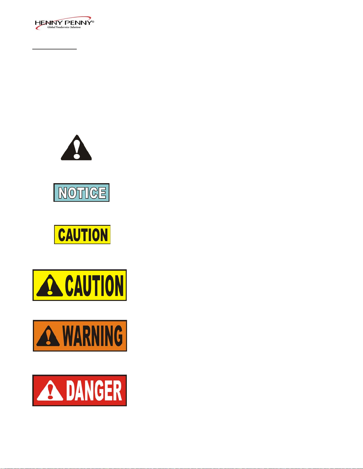
the words DANGER, WARNING , CAUTION, and NOTICE are
used. Their usage is described below .
SAFETY ALER T SYMBOL is used with DANGER,
W ARNING, or CAUTION which indicates a personal injury
type hazard.
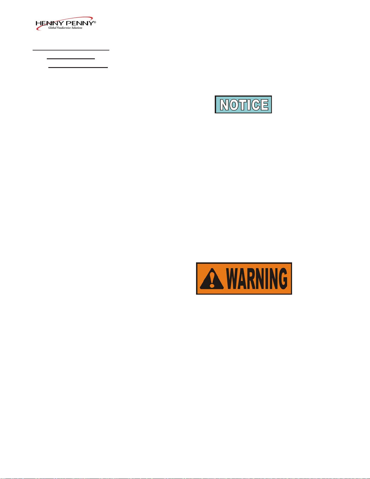
NOTICE is used to highlight especially important information.
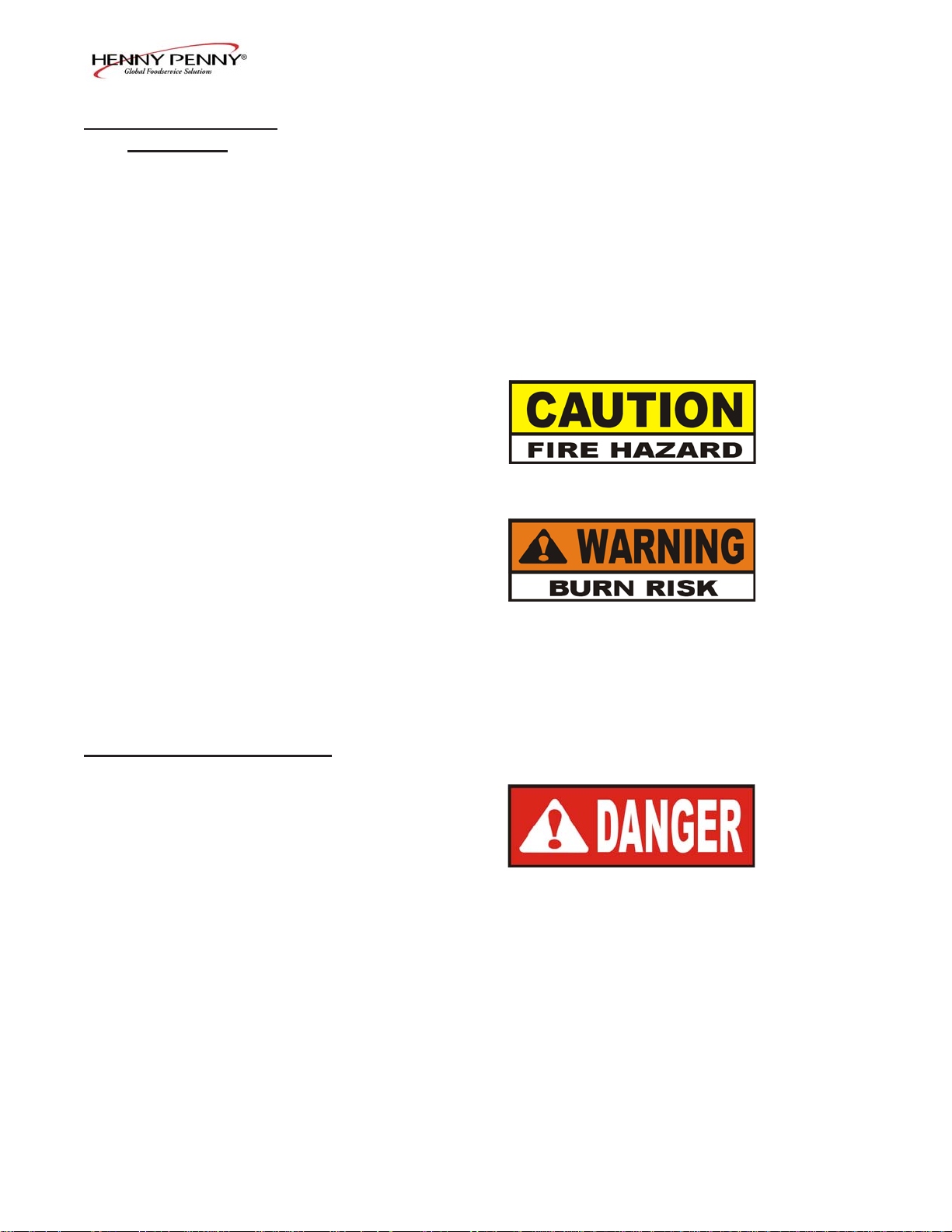
CAUTION used without the safety alert symbol indicates
a potentially hazardous situation which, if not avoided,
may result in property damage.
CAUTION used with the safety alert symbol indicates a
potentially hazardous situation which, if not avoided,
may result in minor or moderate injury.
W ARNING indicates a potentially hazardous situation
which, if not avoided, could result in death or serious
injury.
DANGER INDICA TES AN IMMINENTL Y
HAZARDOUS SITUA TION WHICH, IF NOT
AVOIDED, WILL RESUL T IN DEA TH OR SERIOUS
INJURY.
1-2 403
Page 9
1-5. SAFETY
(Continued)
Model PFE- 590/592
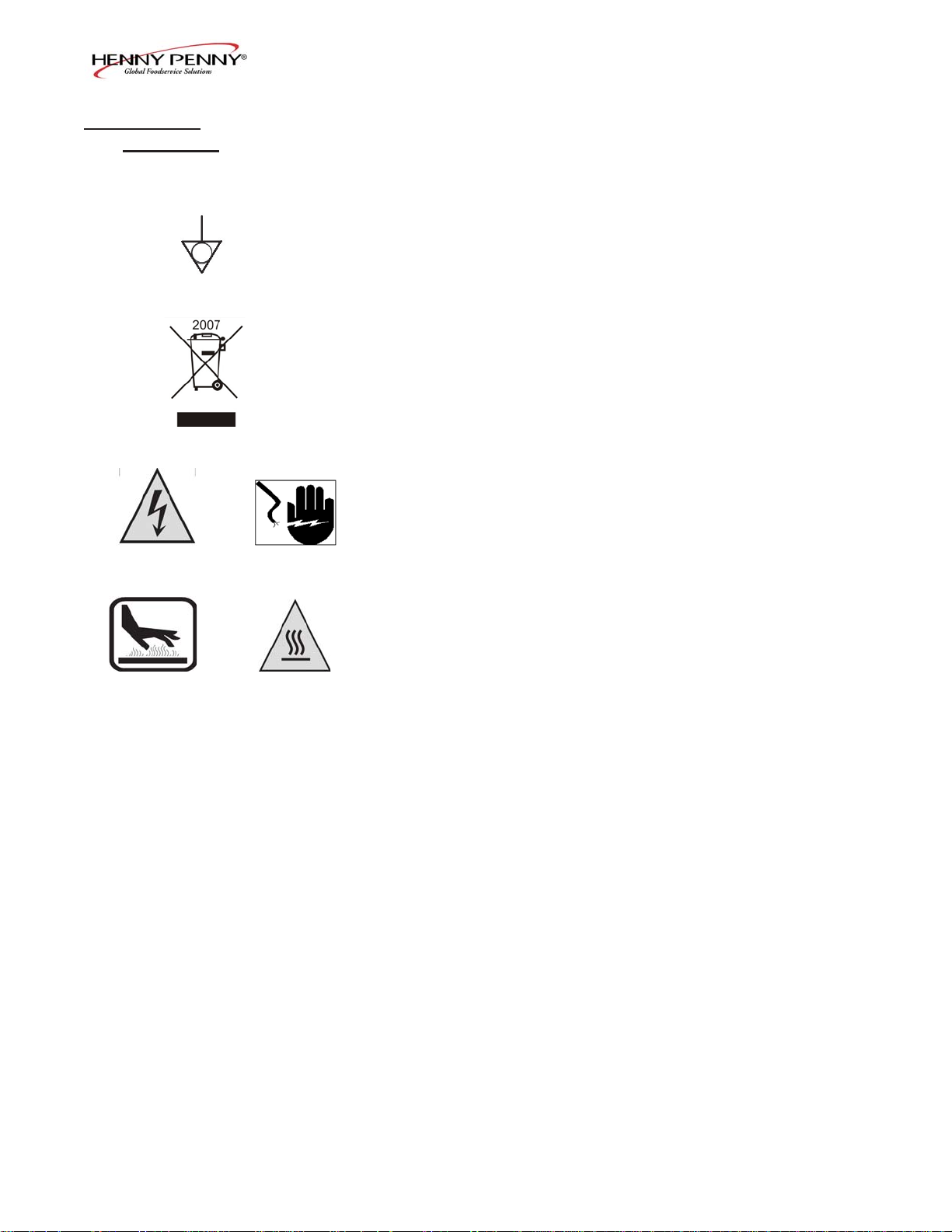
Equipotential Ground Symbol
W aste Electrical and Electronic Equipment (WEEE) Symbol
Shock Hazard Symbols
OR
OR
Hot Surface Symbols
908 1-3
Page 10
SECTION 2. INST ALLA TION
Model PFE- 590/592
2-1. INTRODUCTION
2-2. UNP ACKING
INSTRUCTIONS
This section provides the installation and unpacking instructions for
the Henny Penny PFE-590.
Installation of this unit should be performed only by a qualified
service technician.
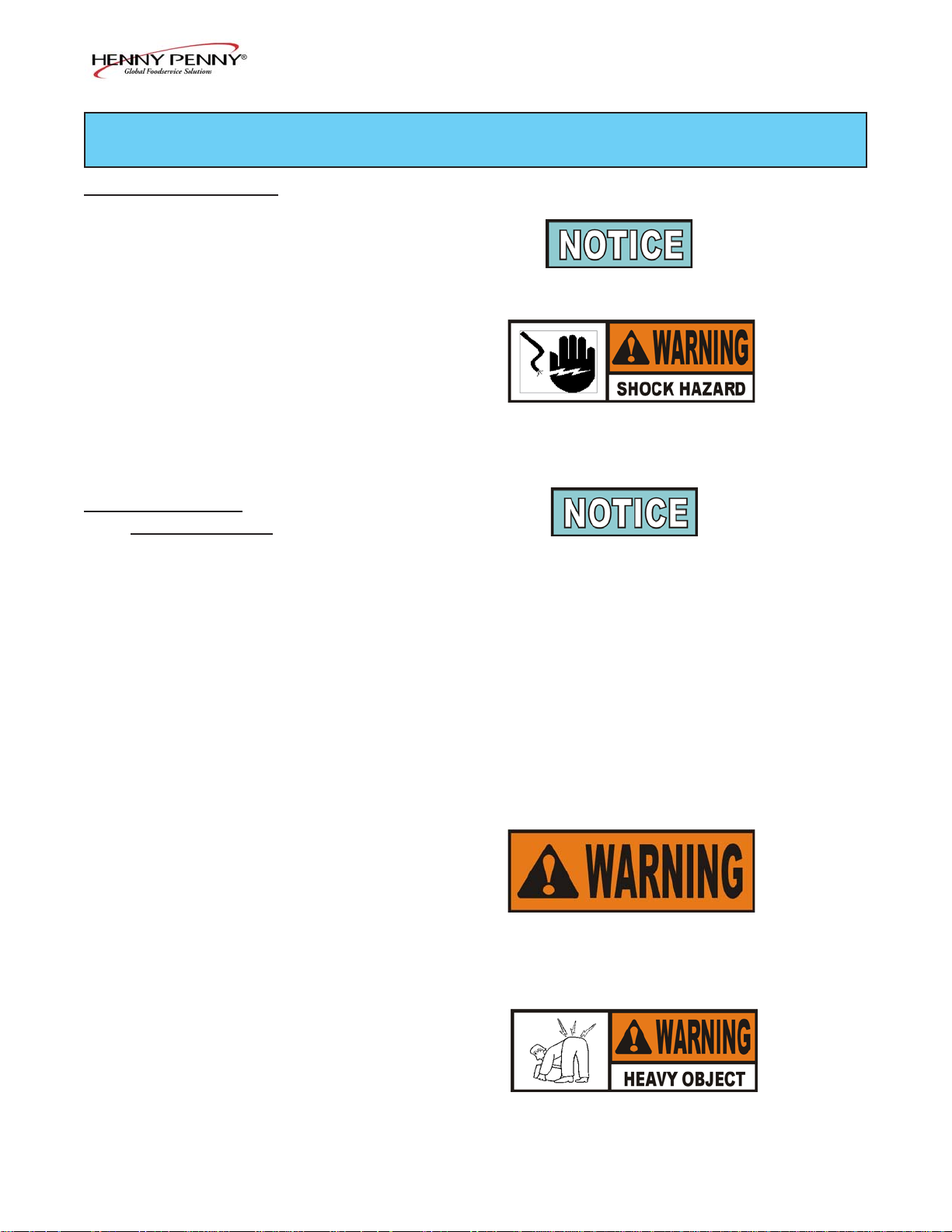
Do not puncture the fryer with any objects such as drills
or screws as electrical shock or component damage
could result.
Any shipping damage should be noted in the presence of the
delivery agent and signed prior to his or her departure.
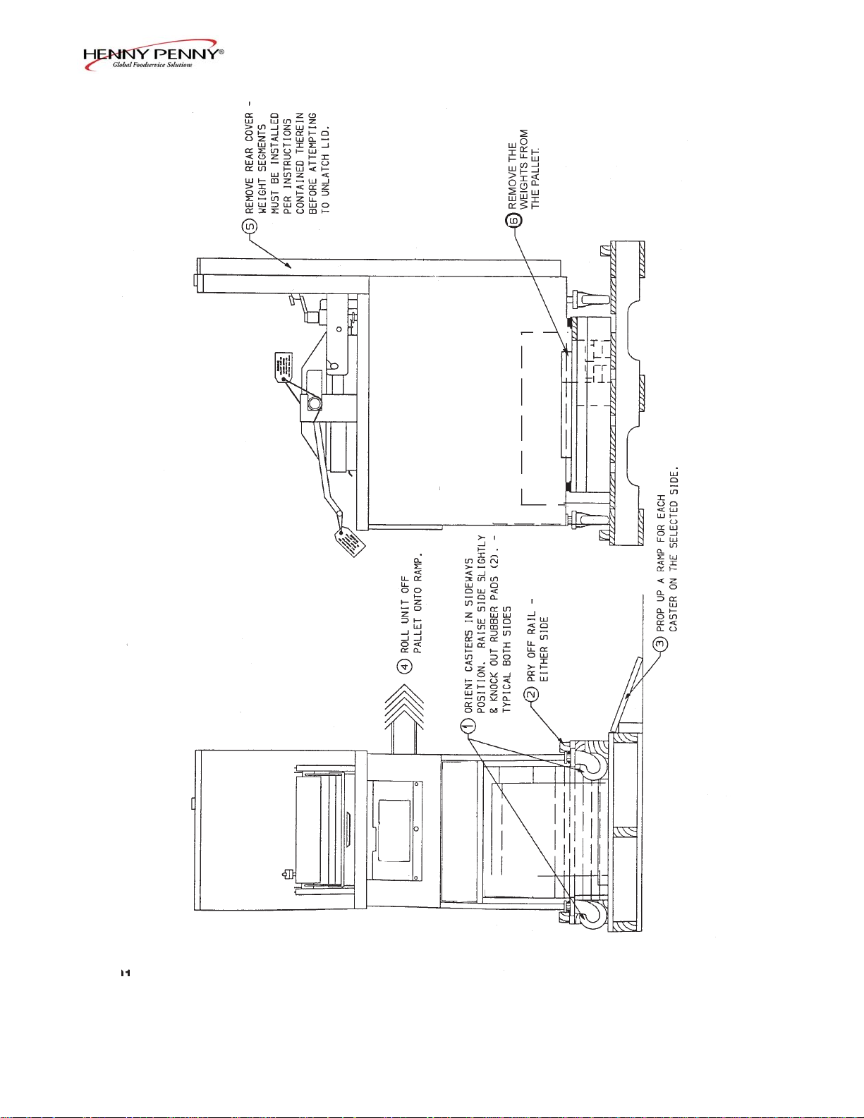
1. Cut and remove the plastic bands from the main box.
2. Remove the box lid and lift the main box off the fryer .
3. Remove corner packing supports (4).
4. Cut the stretch film from around the carrier/rack box and
remove it from the top of the fryer lid.
5. Cut and remove the metal bands holding the fryer to the
pallet.
All counterweights must be loaded before unlatching
lid, or personal injury could result.
6. Remove the fryer from the pallet.
T ake care when moving the fryer to prevent personal
injury . The fryer weighs approximately 758 lbs.
(344 Kg).
2-1 803
Page 11
Model PFE- 590/592
2-2. UNP ACKING
INSTRUCTIONS
(Continued)
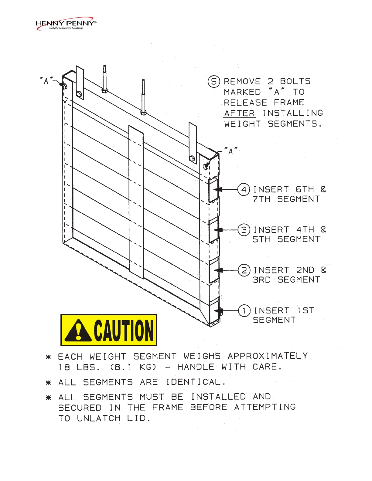
7. Remove the counterweights from the pallet, which are
strapped to the pallet, under the fryer.
Do not drop. The counterweights weigh approximately
18 lbs. (8.1 kg.) each. Handle with care, or personal
injury could result.
8. Remove rear service cover .
9. Load the seven weights into the counterweight assembly . See
page 2-4.
10. Replace rear service cover.
T o avoid personal injury and assur e safe operation of
unit, rear service cover must be in place.
11. Cut warning tags from the lid assembly. The lid may now
be unlatched.
12. Remove the accessories from inside the filter drain pan.
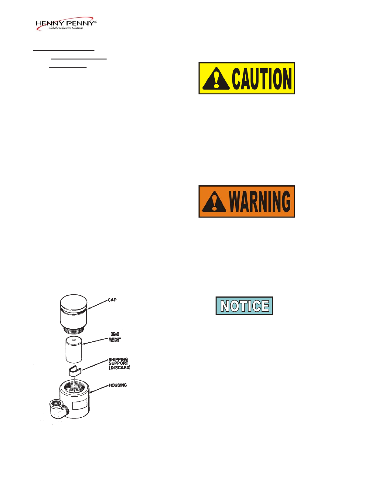
13. Prepare the deadweight valve for operation
The metal shipping support is placed within the deadweight
assembly housing to protect the deadweight orifice and deadweight during shipment. This support must be removed prior
to installation and start-up.
A. Unscrew the deadweight cap.
B. Remove the deadweight.
C. Remove and discard the metal packing support.
D. Clean the deadweight orifice with a dry cloth.
E. Carefully place deadweight over deadweight orifice.
Replace deadweight cap, finger tight.
13. Remove the protective paper from the fryer cabinet.
Clean exterior surface with a damp cloth.
404 2-2
Page 12
Optional Ramp Unloading
Model PFE- 590/592
2-3 1103
Page 13
Model PFE- 590/592
404 2-4
Page 14
Model PFE- 590/592
2-3. SELECTING THE
LOCATION
The proper location of the fryer is very important for operation,
speed, and convenience. Choose a location which will provide
easy loading and unloading without interfering with the final assembly of food orders. Operators have found that frying from raw to
finish, and holding the product in a warmer provides fast continuous
service. Landing or dumping tables should be provided next to at
least one side of the fryer. Keep in mind the best ef ficiency will be
obtained by a straight line operation, i.e. raw in one side and finish
out the other side. Order assembly can be moved away with only
a slight loss of efficiency . T o properly service the fryer, 24 inches
(60.96 cm) of clearance is needed on all sides of the fryer. Access
for servicing can be attained by removing a side panel.
To avoid fire and ruined supplies, the area under the
fryer should not be used to store supplies.
2-4. LEVELING THE FRYER
T o prevent sever e burns from splashing hot shortening,
position and install fryer to prevent tipping or movement. Restraining ties may be used for stabilization.
For proper operation, level the fryer from side to side and front to
back, using level on the flat areas around the frypot collar.
FAILURE TO FOLLOW THESE LEVELING
INSTRUCTIONS CAN RESUL T IN SHOR TENING
OVERFLOWING THE FRYPOT WHICH COULD
CAUSE SERIOUS BURNS, PERSONAL INJUR Y ,
FIRE AND/OR PROPERTY DAMAGE.
2-5 703
Page 15

Model PFE- 590/592
2-5. VENTILATION OF FR YER The fryer should be located with provision for venting into
adequate exhaust hood or ventilation system. This is essential
to permit efficient removal of steam exhaust and frying odors.
Special precaution must be taken in designing an exhaust canopy to
avoid interference with the operation of the fryer. W e recommend
you consult a local ventilation or heating company to help in designing an adequate system.
V entilation must conform to local, state, and national codes.
Consult your local fire department or building authorities.
2-6. ELECTRICAL The electric fryer requires 208 or 240 volt, three phase, 50/60
REQUIREMENTS Hertz service. The power cord may be already attached to the
fryer, or provided at installation. Check the data plate mounted just
above the lid, on the left side of the back shroud, to determine the
correct power supply .
This fryer must be adequately and safely grounded
(earthed) or electrical shock could result. Refer to local
electrical codes for correct grounding (earthing) procedures or in absence of local codes, with The National
Electrical Code, ANSI/NFPA No. 70-(the curr ent edition). In Canada, all electrical connections are to be
made in accordance with CSA C22.1, Canadian Electrical Code Part 1, and/or local codes.
T o avoid electrical shock, this appliance must be
equipped with an external circuit breaker which will
disconnect all ungrounded (unearthed) conductors. The
main power switch on this appliance does not disconnect
all line conductors.
A separate disconnect switch with proper capacity fuses or breakers must be installed at a convenient location between the fryer and
the power source. It should be an insulated copper conductor
rated for 600 volts and 90o C. For runs longer than 50 feet
(15.24 m), use the next larger wire size.
706 2-6
Page 16
Model PFE- 590/592
2-7. INTERNA TIONAL Units being used outside the United States may not be shipped
ELECTRICAL with the power cord attached to the unit because of the different
REQUIREMENTS wiring codes. The fryers are available from the factory wired for
208, 240, 380 and 415 volts, 3 phase, 50 Hertz service. A terminal
block is mounted inside the fryer for the cable wiring. A decal on
the inside of the right side panel will help in the wiring of the unit.
CE units require a minimum wire size of 4mm to be wired to
the terminal block. If a flexible power cord is used, it must be
HO7RN type.
T o install the power cord, follow these procedures:
1. Remove the right side panel of the unit.
2. Install the cord, with a strain relief, to the junction box.
3. Attach the wires to the terminal block according to the wiring
diagram on the side panel.
4. Pull the slack out of the cord and thread it down through the
the clamp on the frame, at the rear, left leg of fryer . Then run
the cable under the frame and out the rear of the fryer, so it
doesn’t interfere with the filter drain pan.
The filter drain pan must be as far back under fryer as
it will go, and the cover in place. Be sure the hole in the
cover lines up with the drain before opening the drain.
Failure to follow these instructions causes splashing of
shortening and could result in personal injury .
5. Wiring the fryer is now complete.
2-7 703
Page 17

2-7. INTERNA TIONAL
ELECTRICAL
REQUIREMENTS
(Continued)
Model PFE- 590/592
• The supply power cords shall be oil-resistant, sheathed flexible
cable, no lighter than ordinary polychloroprene or other
equivalent synthetic elastomer-sheathed cord.
• It is recommended that a 30 mA rated protective device such as
a residual current circuit breaker (RCCB), or ground fault
circuit interrupter (GFCI), be used on the fryer circuit.
(FOR EQUIPMENT WITH CE MARK ONL Y!)
T o prevent electric shock hazard this appliance must be
bonded to other appliances or touchable metal surfaces in
close proximity to this appliance with an equipotential
bonding conductor . This appliance is equipped with an
equipotential lug for this purpose. The equipotential lug is
marked with the following symbol .
908 2-8
Page 18

Model PFE- 590/592
BOIL-OVER PREVENTION IN HENNY PENNY COOKERS
F AILURE TO FOLLOW THESE INSTRUCTIONS CAN RESUL T IN SHOR TENING
OVERFLOWING THE FR YPOT WHICH COULD CAUSE SERIOUS BURNS,
PERSONAL INJUR Y . FIRE AND/OR PROPERTY DAMAGE.
• THE SHORTENING MA Y BE STIRRED ONLY DURING THE MORNING
ST ART UP PROCEDURE. DO NOT STIR THE SHORTENING AT ANY
OTHER TIME.
• FIL TER THE SHORTENING A T LEAST TWICE A DA Y .
• FIL TER ONL Y WHEN “COOL” IS DISPLA YED.
• BRUSH ALL CRACKLINGS FROM FR YPOT SURF ACES AND THE COLD
ZONE DURING THE FILTERING PROCESS.
• MAKE SURE THE FRYER IS LEVEL.
• BE CERT AIN THE SHOR TENING IS NEVER ABOVE THE UPPER FR YPOT
LEVEL INDICA T OR LINE.
• BE CERT AIN THA T THE GAS CONTROL VALVE AND BURNERS ARE
PROPERL Y ADJUSTED. (GAS UNITS ONLY)
• USE RECOMMENDED PRODUCT LOAD SIZE
FOR ADDITIONAL INFORMA TION ON THESE INSTRUCTIONS, REFER TO THE
HENNY PENNY OPERA TOR MANUAL AND THE KFC ST ANDARDS LIBRARY.
FOR ASSIST ANCE CALL THE HENNY PENNY SERVICE DEPARTMENT AT
1-800-417-8405.
or
1-937-456-8405
2-9 703
Page 19

Model PFE- 590/592
Page 20

Model PFE- 590/592
SECTION 3. OPERA TION
3-1. OPERA TING COMPONENTS
POWER/PUMP Switch A three way switch with center OFF position; move the switch to
the position marked POWER to operate the fryer; move the switch
to the position marked PUMP to operate the filter pump; certain
conditions must be met prior to operation of the filter pump; these
conditions are covered later in this section
Frypot This reservoir holds the cooking shortening, and is designed to
accommodate the heating elements, 8 head of product and an
adequate cold zone for collection of cracklings
Carrier This stainless steel carrier consists of five racks, containing the food
product during and after frying (4 cook racks and 1 cover rack)
Lid Gasket Provides the pressure seal for the frypot chamber
Deadweight assembly The deadweight style operating pressure relief valve is used to
maintain a constant level of steam pressure within the frypot;
any excess steam pressure is vented through the exhaust stack;
remove the deadweight cap, and clean the cap, weight, and
deadweight orifice once a day . See Preventive Maintenance
Section.
Failure to clean the deadweight assembly daily could
result in the fryer building too much pressure. Severe
injuries and burns could result.
Safety Relief Valve An ASME approved spring loaded valve set at 14.5 psi
(999 mbar); in the event the operation valve becomes obstructed,
this safety valve releases excess pressure, keeping the frypot
chamber at 14.5 psi (999 mbar); if this occurs, turn the COOK/
PUMP switch to the OFF position to release all pressure from the
frypot
If safety relief valve activates, turn main power switch
to the OFF position. To avoid serious burns and
injuries, have fryer serviced before next use.
3-1 703
Page 21

Model PFE- 590/592
3-1. OPERA TING COMPONENTS
(Continued)
Safety Relief Valve Ring
DO NOT PULL THIS RING. SEVERE BURNS FROM
THE STEAM WILL RESUL T .
Pressure Gauge Indicates the pressure inside the frypot.
Solenoid V alve An electromechanical device that causes pressure to be held in the
frypot
The solenoid valve closes at the beginning of the Cook Cycle and
opens automatically at the end of the Cook Cycle; if this valve
becomes dirty or the teflon seat nicked, pressure will not build and
it must be repaired per the Maintenance Section of the T echnical
Manual
Drain V alve A two-way ball valve, normally in the closed position; turn the han-
dle to drain the shortening from the frypot into the filter drain pan
DO NOT OPEN THE DRAIN VALVE WHILE
FRYPOT IS UNDER PRESSURE. HOT SHORTENING WILL EXHAUST , AND SEVERE BURNS WILL
RESULT.
Drain Interlock Switch A microswitch that provides protection for the frypot in the event an
operator inadvertently drains the shortening from the frypot while
the main switch is in the COOK position; the switch is designed to
automatically shut off the heat when the drain valve is opened
Condensation Drain Pan The collection point for the condensation formed within the steam
exhaust system; it must be removed and emptied periodically ,
usually daily
Shortening Mixing System The unit is equipped with a shortening mixing capability to ensure
the shortening is properly mixed to prevent an accumulation of
moisture, causing boiling action in the frypot; the filter pump is
activated by the controls, at preset intervals, to mix the shortening
Lid Latch The fryer lid is equipped with a mechanical catch on the front
of the lid which engages a bracket on the front of the frypot; this
device holds the lid down while the lid is being locked into
place, but is not meant to hold pressure in the frypot
703 3-2
Page 22

Model PFE- 590/592
3-1. OPERA TING COMPONENTS (Continued)
High T emperature Limit This is a safety component that senses the temperature of the
shortening; if the temperature of the shortening exceeds 420°F
(212°C), this control opens and shuts off the heat to the frypot;
when the temperature of the shortening drops to a safe operation
limit, the control must be manually reset by pressing the red reset
button, located under the control panel, in the right, front of the
fryer
Figure 3-1
Air V alve Pumps air into the shortening, periodically , to keep the shortening at
a uniform temperature; this only functions when the unit has been
sitting idle for a period of time, and when heating from a cold start
Filter Drain Pan The removable pan that houses the filter and catches the shortening
when it is drained from the frypot; also used to remove anddiscard
old shortening
When hot shortening is in this pan, use extreme care to
avoid burns.
Filter Union Connects the filter to the filter pump, and allows easy removal of the
filter and drain pan
Fuses A protective device which breaks the circuit when the current
exceeds the rated value
3-2. LID OPERA TION T o close lid:
1. Lower the lid until gasket comes into contact with the
frypot and lock the lid in place with the lid latch.
2. Pull lid handle forward until it stops.
3. Lift up on the lid handle until it stops.
4. Bring lid handle out towards you until it stops.
5. Push lid handle down, locking lid in place.
LID MUST BE LA TCHED PROPERL Y OR PRESSURIZED SHORTENING AND STEAM MAY
ESCAPE FRYPOT . SEVERE BURNS WILL RESUL T .
3-3 703
Page 23

3-2. LID OPERA TION Continued)
Model PFE- 590/592
DO NOT LIFT HANDLE OR FORCE LID LA TCH
OPEN BEFORE PRESSURE GAUGE READS “0”
PSI. ESCAPING STEAM AND SHOR TENING WILL
RESUL T IN SEVERE BURNS.
TO AV OID SERIOUS PERSONAL INJUR Y , DO NOT
OPERA TE WITHOUT LID COVER IN PLACE AND
ALL COMPONENTS INST ALLED.
TO AV OID SERIOUS PERSONAL INJUR Y , DO NOT
T AMPER WITH ANY COMPONENT OF LID
LOCKING MECHANISM.
T o open lid:
1. Gently raise handle until it stops.
2. Push handle back until it stops.
3. Lower handle.
Lower the handle before attempting to raise the lid, or
damage to the lid could result.
4. Push handle back.
5. Unlatch the front lid latch.
3-3. MEL T CYCLE OPERA TION If the shortening is below 185o F (85o C), with the POWER/PUMP
switch in the POWER position, the fryer will enter the Melt Cycle.
The shortening heats slowly to prevent scorching of the shortening.
The heat cycles on and off to slowly melt the shortening. At 185o F
(85o C), the heat stays on until 250o F (121o C), the Cool Mode,
is reached. T o exit the Cool Mode, press the EXIT COOL button.
See Filling and Adding Shortening Section.
703 3-4
Page 24

Model PFE- 590/592
3-4. SWITCHES AND Refer to image at end of this section.
INDICATORS
EXIT COOL Button After cooking, or filtering the shortening, the temperature automati-
cally goes into the Cool Mode, which keeps shortening at a lower
temperature; this temperature extends the shortening life and
minimizes the time to heat the shortening for the next Cook Cycle;
EXIT COOL button must be pressed to heat up to setpoint temperature
AL THOUGH THE DISPLA Y WILL READ “COOL”
DURING THE STANDBY MODE, THE SHOR TENING IS HOT AND WILL CAUSE BURNS.
Product Selection Buttons Select the number of heads, or product, to be cooked by pressing
the button below the menued item; shortening will then heat to
drop temperature of that item
Pressing the same button again will begin the Cook Cycle; the
indicator will change from “DROP” to counting down the cook
time in minutes and seconds
At the end of the Cook Cycle, the alarm sounds and the indicator
reads “DONE”; press the cycle button that is flashing, and the
alarm will cease; the fryer will then reset to the Cool Mode
A Cook Cycle can be aborted at any time by pressing and
holding the product button.
Time/T emperature Display This is a 4 digit LED type display which shows the remaining cook
time during Cook Cycles and also the shortening temperature on
demand from the operator
Heat Indicator Illuminates whenever the control calls for heat; when shortening
temperature is reached, the heat light goes off
3-5 703
Page 25

Model PFE- 590/592
3-4. SWITCHES AND
INDICA TORS (Continued)
HI T emperature Indicator The display reads “HI” if the shortening temperature is 40° F above
the setpoint
Drop Indicator The display reads “DROP” when the shortening has reached
the setpoint temperature (will read “DROP” 2° before setpoint and
4° above setpoint )
Done Indicator The display reads “DONE” at the end of the Cook Cycle
T emperature Button Allows the operator to read the temperature of the shortening while
in a Cook Cycle
SCAN Button Allows the operator to toggle through any running multiple timers
FUNCTION Button Used in the programming of the controls
EXIT FILL Button After filtering the fryer, if in the Filter Lockout Mode, the display
reads “FILL” and the EXIT FILL button must be pressed
Multiple Timers The control has the capability to run multiple timers; if more than
one product is being cooked, a timer can be started by pressing
more than one product button per Cook Cycle
The products must have the same setpoints, and the pressure
must be programmed off. See Programming Section.
703 3-6
Page 26

3-4. SWITCHES AND
INDICA TORS (Continued)
Model PFE- 590/592
TEMPERA TURE BUTTON DIGITAL DISPLAY
PRODUCT BUTTONS
Figure 3-2
3-7 403
Page 27

3-5. FILLING OR ADDING
SHORTENING
Model PFE- 590/592
The shortening level must always be above the heating
elements when the fryer is heating and at the frypot level
indicators on the rear of the frypot (Figure 3-3). Failure
to follow these instructions could result in a fire and/or
damage to the fryer.
When using solid shortening, it is recommended to melt
the shortening on an outside heating source befor e placing it in the frypots. The heating elements must be
completely submerged in shortening. Fir e or damage to
the frypot could result.
1. It is recommended that a high quality frying shorteningbe used
in the pressure fryer. Some low grade shortenings have a high
moisture content and cause foaming and boiling over .
Figure 3-3
T o avoid severe burns when pouring hot shortening into
frypot, wear gloves and take care to avoid splashing.
2. The electric model requires 100 lbs. (45 kg.) of shortening.
The frypot has 2 level indicator lines inscribed on the rear
wall of the frypot which show when the heated shortening is at
the proper level. Figure 3-3.
3. Cold shortening should be filled to the lower indicator.
BE CERT AIN THE SHORTENING IS NEVER
ABOVE THE UPPER LEVEL INDICA TOR LINE.
FAILURE TO FOLLOW THESE INSTRUCTIONS
CAN RESUL T IN SHOR TENING OVERFLOWING
THE FRYPOT CAUSING SERIOUS BURNS, PERSONAL INJUR Y , FIRE AND/OR PROPERTY
DAMAGE.
For complete instructions, refer to KFC’s S tandards Library .
703 3-8
Page 28

Model PFE- 590/592
3-6. BASIC OPERA TION Follow the procedure below on the initial start-up of the fryer , and
each time the fryer is brought from a cold, or shut down condition,
back into operation. These are basic, general instructions. Be sure
to follow KFC’ s Standards Library when operating the fryer.
1. Make sure the frypot is filled to the proper level with shortening, to the lower level indicator.
DO NOT OVERLOAD, OR PLACE PRODUCT WITH
EXTREME MOISTURE CONTENT INTO THE
RACKS. 22 LBS. (9.9 KG.) IS THE MAXIMUM
AMOUNT OF PRODUCT PER FRYPOT . FAILURE
TO FOLLOW THESE INSTRUCTIONS CAN RE
SUL T IN SHOR TENING OVERFLOWING THE
FRYPOT WHICH COULD CAUSE SERIOUS
BURNS, PERSONAL INJUR Y , FIRE AND/OR
PROPERTY DAMAGE.
2. Turn the POWER/PUMP switch to the POWER position and
press the appropriate product button to select the amount
of product to be cooked.
3. Stir the shortening as it’ s heating up from a cold start.
Be sure to stir down into the cold zone.
DO NOT STIR THE SHORTENING A T ANY OTHER
TIME EXCEPT A T MORNING ST AR T -UP . FAILURE
TO FOLLOW THESE INSTRUCTIONS CAN RESUL T IN SHOR TENING OVERFLOWING THE
FRYPOT WHICH COULD CAUSE SERIOUS
BURNS, PERSONAL INJUR Y , FIRE, AND/OR
PROPERTY DAMAGE.
3-9 703
Page 29

Model PFE- 590/592
3-6. BASIC OPERA TION 4. Allow fryer to heat until digital display shows “DROP”.
(Continued) (Press the EXIT COOL button if the display shows COOL”)
The heat cycles on and off approximately 10 degrees before
the setpoint temperature, to help prevent overshooting the
setpoint temperature. (proportional control)
5. Before loading product onto the racks, lower racks into the
hot shortening to keep the product from sticking to the racks.
6. Slide racks of breaded product into carrier on the lid, starting
with the bottom tier, to prevent damaged product.
7. Lower and lock the lid down and press the appropriate
product button (2, 4, 6, or 8 head).
8. At the end of the cycle, pressure begins venting automatically,
alarm sounds, and the display shows “DONE”. At this time,
press the appropriate product button (2, 4, 6, or 8 head).
9. W ait for the pressure gauge to show “0” pressure in the
frypot before attempting to open the lid.
DO NOT LIFT HANDLE OR FORCE LID LA TCH
OPEN BEFORE PRESSURE GAUGE READS “0”
PSI. ESCAPING STEAM AND SHOR TENING WILL
RESUL T IN SEVERE BURNS.
10. Unlock and raise the lid cautiously.
11. Using the rack handles, remove the racks of product from
the carrier, starting with the top rack.
703 3-10
Page 30

3-7. CARE OF THE
SHORTENING
Model PFE- 590/592
FOLLOW THE INSTRUCTIONS BELOW TO A V OID
SHORTENING OVERFLOWING THE FR YPOT ,
WHICH COULD RESUL T IN SERIOUS BURNS,
PERSONAL INJUR Y , FIRE, AND/OR PROPERTY
DAMAGE.
1. T o protect the shortening when the fryer is not in immediate
use, the fryer should be put into the Cool Mode.
2. Frying breaded products requires filtering to keep the
shortening clean. The shortening should be filtered at
least twice a day: after lunch rush and at the end of the day .
3. Maintain the shortening at the proper cooking level. Add
fresh shortening as needed.
4. Do not overload the racks with product (22 lbs. (9.9 kgs.)
maximum), or place product with extreme moisture content
into racks.
WITH PROLONGED USE, THE FLASHPOINT OF
SHORTENING IS REDUCED. DISCARD SHORTENING IF IT SHOWS SIGNS OF EXCESSIVE
SMOKING OR FOAMING. SERIOUS BURNS,
PERSONAL INJUR Y , FIRE, AND/OR PROPERTY
DAMAGE COULD RESUL T .
3-8. FIL TERING The Henny Penny electric 8 head pressure fryer, Model 590, should
INSTRUCTIONS be cleaned and the shortening filtered and polished at least twice
daily; after lunch rush and at the end of the day . Refer to KFC’s
Standards Library .
Filter shortening immediately following a Cook Cycle when the
shortening temperature is in the Cool Mode.
Drain the shortening at 250° F (121° C) or less. Higher
temperatures cause cracklings to burn on the steel frypot
surfaces after the shortening has drained.
3-11 703
Page 31

3-8. FIL TERING
INSTRUCTIONS
(continued)
Model PFE- 590/592
ONLY FILTER WHEN “COOL” IS DISPLAYED.
FAILURE TO DO SO CAN RESULT IN SHORTENING
OVERFLOWING THE FRYPOT, CAUSING SERIOUS
BURNS, PERSONAL INJURY, FIRE,AND/OR
PROPERTY DAMAGE.
High volume cooking could cause the cold zone to fill quicker with
cracklings and cleaning may be required more often. Part of the
filtering process involves removing cracklings from the cold zone of
the frypot.
1. Turn POWER/PUMP switch to OFF position.
2. Make sure filter drain pan is under fryer and the filter union
is fastened to the filter standpipe, coming out of the pan.
Shortening Stirrer
Drain Cleanout Small White
Rod Brush
The filter drain pan must be as far back under fryer as
it will go, and the cover in place. Be sure the hole in the
cover lines up with the drain before opening the drain.
Failure to follow these instructions causes splashing of
shortening and could result in personal injury.
Surfaces of fryer and racks will be hot. Use care when
filtering to avoid getting burned.
3. Remove cooking racks, carrier and wipe bottom of lid. Tilt
lid out of the way to clean frypot.
4. Pull drain handle towards you to open drain valve. The handle
should point straight out to the front of the fryer. Use large
white brush to clean cracklings from the elements and from
sides and bottom of frypot as shortening drains. Use the drain
cleanout rod to push cracklings through drain opening in bottom
of frypot if necessary. Using the small straight white brush,
clean between the elements and the frypot wall.
BRUSH ALL CRACKLINGS FROM FRYPOT SURFACES AND THE COLD ZONE DURING THE FILTERING PROCESS. FAILURE TO DO SO CAN
RESULT IN SHORTENING OVERFLOWING THE
FRYPOT, WHICH COULD CAUSE SERIOUS BURNS,
PERSONAL INJURY, FIRE AND/OR PROPERTY
703 3-12
DAMAGE.
Page 32

Model PFE- 590/592
3-8. FIL TERING 5. Scrape cracklings and crackling ring from frypot and discard.
INSTRUCTIONS Do not let cracklings drain into filter drain pan. These crack-
(Continued) lings can cause a burned taste in gravy . Wipe all surfaces with
a clean damp towel. If water drops into cold zone, dry with
towel before pumping shortening back into the frypot.
Do not bang the pot scraper, or other cleaning utensil, on
the frypot rim. Damage to the frypot rim could result and
the lid may not seal properly during a cook cycle.
6. Return drain handle to the closed position to close the drain.
7. Turn POWER/PUMP switch to PUMP , and when all shortening has been pumped into frypot swing drain handle to
the closed position to close the drain.
IF THERE ARE AIR BUBBLES COMING UP IN THE
SHORTENING, IT’S POSSIBLE THA T THE FIL TER
CONNECTION A T THE UNION ON THE FILTER
TUBE IS NOT TIGHTENED PROPERL Y. IF SO,
TURN OFF THE PUMP AND USE PROTECTIVE
CLOTH OR GLOVE WHEN TIGHTENING THE
UNION. THIS UNION WILL BE HOT AND SEVERE
BURNS WILL RESULT .
3-9. CHANGING THE FIL TER The filter envelope should be changed after 10-12 filterings, or
ENVELOPE whenever it becomes clogged with crumbs. Refer to KFC’s
Standards Library .
Use protective cloth or glove when disconnecting the
filter union or severe burns could result.
If the filter pan is moved while full of shortening, use
care to prevent splashing, or severe burns could result.
Be sure that the filter screens, crumb catcher, filter clips
and the standpipe are thoroughly dry before assembly of
the filter envelope or water will dissolve the filter paper.
3-13 605
Page 33

Model PFE- 590/592
3-10. CLEANING THE FRYPOT After the initial installation of the fryer, as well as before every
change of shortening, the frypot should be thoroughly cleaned as
follows:
1. Turn the POWER/PUMP switch to OFF positioin, and
unplug unit from wall receptacle.
Moving the fryer or filter drain pan while containing
hot shortening is not recommended. Hot shortening can
splash out and severe burns could result.
The filter drain pan must be as far back under fryer as
it will go, and the cover in place. Be sure the hole in the
cover lines up with the drain before opening the drain.
Failure to follow these instructions causes splashing
of shortening and could result in personal injury .
2. If hot shortening is present in the frypot, it must be
drained by slowly pulling the drain handle out towards you.
3. Close the drain valve and discard the shortening.
4. Raise lid, remove the racks and carrier from lid, and tilt lid
back, so that the lid won’t interfere with cleaning.
5. Refer to KFC’ s Standard’ s Library on cleaning instructions.
DO NOT CLOSE LID WITH WA TER AND/OR
CLEANER IN FRYPOT . WA TER UNDER PRESSURE BECOMES SUPERHEA TED. WHEN LID IS
OPENED, ESCAPING WA TER AND STEAM WILL
RESUL T IN SEVERE BURNS.
If the cleaning solution in the frypot starts to foam and
boil over , immediately turn the power switch to OFF
and do not try to contain it by closing the fryer lid
or severe burns could result.
703 3-14
Page 34

Model PFE- 590/592
3-10. CLEANING THE FRYPOT
(Continued)
Do not use steel wool, other abrasive cleaners or cleaners/sanitizers containing chlorine, bromine, iodine or
ammonia chemicals, as these will deteriorate the stainless steel material and shorten the life of the unit.
Do not use a water jet (pressure sprayer) to clean the
unit, or component damage could result.
Make sure the inside of the frypot, the drain valve opening,
and all parts that come in contact with the new shortening are
as dry as possible.
3-11. FIL TER PUMP MOT OR The filter pump motor is equipped with a manual reset button,
PROTECTOR-MANUAL located on the rear of the motor, in case the motor overheats. If
RESET motor won’t run, wait about 5 minutes before attempting to reset
this protective device to allow motor to cool. Remove the access
panel on the left side panel of the unit to reset the button. It takes
some effort to reset, and a screwdriver can be used to help reset
the button.
T o prevent burns caused by splashing shortening, turn
the unit’s main power switch to the OFF position before
resetting the filter pump motor’ s manual reset
protection device.
3-12. REGULAR As in all food service equipment, the Henny Penny pressure fryer
MAINTENANCE does require care and proper maintenance. The table below
SCHEDULE provides a summary of scheduled maintenance. The following
paragraphs provide preventive maintenance procedures to be
performed by the operator .
Procedure Frequency
Filtering of shortening See KFC’ s Standards Library
Changing of shortening See KFC’s S tandards Library
Changing the filter envelope See KFC’s S tandards Library
Cleaning the deadweight assy . Daily-see Preventive
Maintenance Section
Cleaning the frypot See KFC’ s Standards Library
Cleaning the Nylatrons Monthly-see Preventive
Maintenance Section
Reversing lid gasket Every 90 Days-see Preventive
Maintenance Section
Lubricate rear lid rollers Annually-see Preventive
Maintenance Section
Cleaning safety relief valve Annually-see Preventive
Maintenance Section
3-15 810
Page 35

3-13. PREVENTIVE Cleaning Deadweight Assembly - Daily
MAINTENANCE
DO NOT A TTEMPT T O REMOVE DEADWEIGHT
CAP WHILE FRYER IS OPERA TING. SEVERE
BURNS OR OTHER INJURIES WILL RESUL T .
At the end of each day’ s usage of the fryer, the deadweight
1.
assembly must be cleaned. The fryer must be off and the
pressure released. Open the lid and then remove the
deadweight valve cap and deadweight.
ORIFICE CAP DEADWEIGHT
Deadweight cap may be hot. Use protective cloth or
glove, or burns could result.
Model PFE- 590/592
EXHAUST TUBE
Failure to clean the deadweight assembly daily could
result in the fryer building too much pressure. Severe
injuries and burns could result.
2. Wipe both the cap and deadweight with a soft cloth. Make
certain to thoroughly clean inside cap, the deadweight seat,
and around deadweight orifice.
3. Clean the exhaust tube with stainless steel brush (Henny
Penny part number 12147).
4. Dry parts and replace right away to prevent damage or loss.
Cleaning Nylatrons - Monthly
1. Spray Henny Penny biodegradable, food safe, foaming
degreaser (part no. 12226) on Nylatrons.
2. Raise lid up and down several times to spread the degreaser.
3. Wipe Nylatrons to remove food soil, grease, and degreaser
residue.
Reversing Lid Gasket - Every 90 Days
Reversing the lid gasket helps to prevent early failure of lid gasket
and the loss of pressure during a cook cycle.
1. Raise the lid and remove racks and carrier.
2. Grasping the lid handle, lift the front of the lid up until it
stops in an upright position.
810 3-16
Page 36

3-13. PREVENTIVE Reversing Lid Gasket (Continued)
MAINTENANCE
Continued)
Be sure the metal arm on the left side of the lid is in the
vertical position holding the lid upright, or severe
injuries could result. (See photo at left.)
3. Using a thin blade screwdriver, pry out the gasket at the
corners. Remove the gasket.
Check the gasket for any tears or nicks. If the gasket is
damaged, it needs to be replaced.
Model PFE- 590/592
4. Clean the gasket and gasket seat with hot water.
5. Rotate the gasket with the opposite side facing out.
Install the 4 corners of the lid gasket. Smooth the
gasket into place, working from the corners towards the
middle of each side.
Lubricating Lid Rollers - Annually
The lid rollers, in the back of the fryer, should be lubricated at
least once a year, to allow the lid easy movement.
1. Remove the back shroud of the fryer .
2. Using spindle lube, part number 12124, place a small amount
of lube on both top and bottom rollers. Make sure to lube
both left and right rollers.
3-17 703
Page 37

3-13. PREVENTIVE Cleaning Safety Relief V alve-Annually
MAINTENANCE
Continued)
SAFETY V AL VE
DO NOT A TTEMPT T O REMOVE SAFETY VAL VE
WHILE FRYER IS OPERA TING, OR SEVERE BURNS
OR OTHER INJURIES WILL RESUL T .
DO NOT DISASSEMBLE OR MODIFY THIS SAFETY
V AL VE. TAMPERING WITH THIS V AL VE COULD
CAUSE SERIOUS INJURIES AND WILL VOID
AGENCY APPROV ALS AND APPLIANCE
WARRANTY .
1. Use a wrench to remove pressure gauge.
2. Use a wrench to loosen the valve from the pipe tee, turn
counterclockwise to remove.
Model PFE- 590/592
3. Clean the inside of the pipe tee with hot water.
Turn the safety relief valve towards the rear of the fryer when
reinstalling the relief valve.
4. Immerse the safety relief valve in a soapy water solution for 24
hours. Use a 1:1 dilution rate. The valve cannot be disassembled. It is factory preset to open at 14-1/2 pounds of
pressure. If it does not open or close, it must be replaced.
703 3-18
Page 38

Model PFE- 590/592
3-14. PROGRAMMING 1. Press and hold the FUNCTION button for two seconds.
“REG PROGRAM” shows in the display , followed by
“CODE”.
2. Press the code 1,2,3. “SELECT PRODUCT” scrolls
across the display .
If no buttons are pressed, within approximately 1 minute
while in the Program Mode, the controls will revert back
to the Cook Mode.
3. Press the appropriate product button, (1-0), to identify
what product you want to program.
4. “INT1” and “TIME” flashes on the left side of the display .
The right side shows the starting time of the Cook Cycle and
can be changed by pressing the appropriate numbers. Ex:
Press 1,0,0,0 and 10:00 flashes on the right side of the
display , setting the start time at 10 minutes.
5. After the time is set, press and release the FUNCTION
button and “INT1” and “TEMP” flashes on the left side
of the display . The right side shows the starting
temperature and can be changed by pressing the appropriate
numbers. Ex: Press 2,5,0 and “250° F” will show on
the right side of the display , setting the start temperature
at 250° Fahrenheit.
6. After the temperature is set, press and release the FUNC-
TION button and “INTI” and “PRESS” flashes on the
left side of the display . Press any of the product buttons,
(1-0), to turn the pressure on or off.
7. After the pressure is set, press and release the FUNCTION
button and “INTI”, “LOAD”, and “COMP” flashes on the
left side of the display . The factory preset load compensation
value shows in the right side of the display .
3-19 703
Page 39

Model PFE- 590/592
3-14. PROGRAMMING 8. After the load compensation, press and release the
(Continued) FUNCTION button. “PROP” and “CONTROL” shows on
the left side of the display and the factory preset proportional
control temperature shows on the right side of the display .
9. After the proportional control, press and release the
FUNCTION button. “ALM 1” and “TIME” flashes in
the left side of the display , and the first alarm time shows
on the right side of the display . T o change the time the
alarm sounds, press the appropriate product buttons to set
the time. Ex: Press 1,0,0,0. 10:00 flashes on the right
side of the display , which means when the timer counts
down to 10 minutes, an alarm will sound.
10. After alarm is set, press and release the FUNCTION
button. “ALM 1”, “SELF-’ ’, and “CANCEL” flashes
in the left side of the display and “YES” or “NO” shows
on the right side of the display . The yes and no can be
toggled by pressing any of the product buttons, (l -0).
“YES” means the alarm tone automatically stops after
several beeps. “NO” means someone must manually
press the appropriate product button to stop the alarm
tone.
11 . Repeat steps 9 and 10 for alarms 2 and 3.
12. After alarm 3 is set, press and release the FUNCTION
button. “FIL TER” and “CYCLES” shows on the left side
of the display and the filter cycle value is on the right side
of the display . The value is the number of Cook Cycles
that must completed before the control signals the operator
that the shortening needs filtered
403 3-20
Page 40

Model PFE- 590/592
3-14. PROGRAMMING 13. After the filter value is set, press and release the FUNCTION
(Continued) button. “EOC” and “EXIT” flashes on the left side
of the display , and “COOL” shows on the right side of the
display . The end-of-cycle (EOC), exit point can be set to
COOL, SETP , or FLTR, by pressing any of the product
buttons (EOC). At the end of a Cook Cycle, the controls
can be set to return to: COOL, the setpoint temperature, or
to signal the operator to filter the shortening.
14. After the end-of-cycle setpoint is set, press and release the
FUNCTION button. “HEAD” and “COUNT” flashes on
the left side of the display and a number shows on the
right side of the display . The number on the right, is the
number of head of chicken to be cooked when that product
button is pressed. The number can be changed by
pressing the appropriate product button.
Another product can be programmed while in the Program
Mode by following these procedures:
Press and hold the SCAN button at any time while in the
Program Mode, and the display scrolls “SELECT
PRODUCT”. Then press any of the product buttons,
(1-0), and now that product can be programmed.
15. T o program second interval, press and release the SCAN
button while in the Time Mode, of the first mode. “INT2”
and “TIME” flashes on the left side of the display . Then
follow the steps above, starting with step 4.
3-15. SPECIAL PROGRAM MODE Review Usage
1. Press and hold the FUNCTION button for two seconds until
“REG PROGRAM” shows in the display . As soon as
“REG PROGRAM” shows in the display , press and release
the FUNCTION button 1 time until “REVIEW USE” shows
in the display .
2. “DAIL Y” shows in the display . Press any of the product
buttons to view the usage of that product. Press and hold the
FUNCTION button to exit Special Program Mode.
3-21 403
Page 41

Model PFE- 590/592
3-15. SPECIAL PROGRAM MODE Reset Usage
(Continued) 1. Press and hold the FUNCTION button for two seconds until
“REG PROGRAM” shows in the display . As soon as “REG
PROGRAM” shows in the display , press and release the
FUNCTION button 2 times until “RESET USE” shows in
display .
2. When “CODE” shows in the display , press 1-3-5. “DAIL Y
will show in the display , and press any of the product buttons
to reset them to 0.
Factory Presets (F/C, Gas/Electric, Speaker Volume,
Speaker Frequency , Codes, Initialize System)
1. Press and hold the FUNCTION button for two seconds until
“REG PROGRAM” shows in the display . As soon as
“REG PROGRAM” shows in the display , press and release
the FUNCTION button 3 times until “F AC PRESET” shows
in the display .
2. When “CODE” shows on the display , enter 2-9-5-7. “DEG”
and “MODE” flashes in the display . Press any of the product
buttons to toggle from ºF to ºC, and vice versa.
3. Press and release the FUNCTION button and “TYPE”
and “FR YR” flashes in the display. Press any of the product
buttons to toggle from “GAS” to “ELEC”, or vice versa.
4. Press and release the FUNCTION button twice, and
“SPKR” and “VOL” flashes in the display . The volume can
be changed from 01 to 10, 10 being the loudest.
5. Press and release the FUNCTION button 3 times, and
“SPKR” and “FREQ” flashes in the display . The frequency
can be set from 100 to 2000.
6. Press and release the FUNCTION button 10 times, and
“INITIALIZE SYSTEM” scrolls across the display . Press
and hold any of the product buttons and the display counts
down from 5. Once the display counts down, release the
product button, and the control sets factory preset parameters into the controls.
Before attempting to change the other modes in the Factory
Preset Mode, please call the Henny Penny T echnical Service
Department at 1-800-417-8405, or 1-937-456-8405.
403 3-22
Page 42

3-15. SPECIAL PROGRAM MODE T ech I/O Mode
(Continued) 1. Press and hold the FUNCTION button for two seconds until
“REG PROGRAM” shows in the display . As soon as
“REG PROGRAM” shows in the display , press and release
the FUNCTION button 4 times until “TECH I-O” shows in
the display .
2. When “CODE” shows in the display , press 2-4-6 (1-7-7-6
for CE units). “HEA T’, “PRESSURE”, and “PUMP”
shows alternately in the display . Also, the LEDs over 1, 2
and 3 flashes alternately .
3. T o test the heat circuit, press and hold the 1 button.
4. T o test the pressure system, press and hold the 2 button.
5. T o test the pump system, press and hold the 3 button.
Model PFE- 590/592
3-23 403
Page 43

Model PFE- 590/592
3-15. SPECIAL PROGRAM Heat Control
MODE (Continued) 1. Press and hold the FUNCTION button for two seconds until
“REG PROGRAM” shows in the display . As soon as
“REG PROGRAM” shows in the display , press and release
the FUNCTION button 6 times until “HEA T CNTRL” shows
in the display .
2. When “CODE” shows in the display , press 1-2-3-4.
“MEL T”, “EXIT”, and “TEMP” flashes in the display , along
with the shortening temperature at which the unit exits the
Melt Cycle. This should be set at 180º F (82º C), and should
not be changed until the factory is consulted.
3. Press and release the FUNCTION button and ”MEL T”,
“CYCLE”, and “100s” shows alternately in the display , along
with the period (pulse) length of 4000. This should not be
changed until the factory is consulted.
4. Press and release the FUNCTION button twice and
“MEL T”, “ON-”, “TIME”, and “100s”, shows alternately in
the display , along with the length of time the heat is on. This
should be set at 1700, and should not be changed until the
factory is consulted.
5. Press and release the FUNCTION button three times and
“COOL”, “SET -”, and “POINT” shows alternately in the
display , along with the temperature at which the control exits
the Melt Cycle. This is set at 250º F (121º C), and should
not be changed until the factory is consulted.
6. Press and release the FUNCTION button four times and
“AUTO”, and “IDLE” shows alternately in the display , along
with “OFF”. This should not be changed until the factory is
consulted.
7. Press and release the FUNCITON button five times and
“AUTO”, “IDLE”, and “MMSS” shows alternately in the
display , along with “0:00”. This should not be changed until
the factory is consulted.
8. The last 3 functions in the Heat Control Mode are used by the
factory only , and should not be changed.
403 3-24
Page 44

Model PFE- 590/592
SECTION 4. TROUBLESHOOTING
4-1. TROUBLE SHOOTING GUIDE
Problem Cause Correction
Power switch on but fryer
completely inoperative
• Open circuit
• Fryer plugged in
• Check breaker or fuse at wall
Pressure not exhausting at
end of Cook Cycle
Operating pressure too high
• Solenoid or exhaust line clogged
• Deadweight clogged
• Turn off and allow fryer to cool to
release the pressure in frypot; have
all lines, solenoid and exhaust tank
cleaned
• Turn off and allow fryer to cool to
release the pressure in frypot; clean
deadweight; see Preventive Mainte-
nance Section
DO NOT OPERATE UNIT IF PRESSURE GAUGE SHOWS HIGH PRESSURE CONDITIONS.
SEVERE INJURIES AND BURNS WILL RESULT. IMMEDIATELY PLACE THE POWER/
PUMP SWITCH IN THE OFF POSITION, WHICH RELEASES THE PRESSURE BY ALLOWING THE UNIT TO COOL. DO NOT RESUME USE OF UNIT UNTIL CAUSE OF HIGH
PRESSURE HAS BEEN FOUND AND CORRECTED.
Pressure does not build
• Not enough product in frypot
• Metal shipping spacer not
removed from deadweight assy.
• Place full capacity product in frypot
when using fresh shortening.
• Remove shipping spacer; see
Unpacking Instructions Section
Shortening not heating
Foaming or boiling over
Shortening not draining
Filter motor won’t run
• Pressure not programmed
• Lid gasket leaking
• Drain valve open
• High temperature limit tripped
• See Boil-Over chart on fryer
and beginning of Operation
Section in this manual
• Drain valve clogged
• Motor overheated
• Check programming
• Reverse or replace lid gasket
• Close drain valve.
• Reset high temperature limit; see
Operating Components Section
• Follow Boil-Over procedures from
chart
• Push cleaning rod through open
drain valve
• Reset motor; see Filter Pump Motor
Protector-Manual Reset Section
More detailed troubleshooting information is available in the T echnical Manual, available at www .hennypenny .com,
or 1-800-417-8405 or 1-937-456-8405.
4-1 703
Page 45

Model PFE- 590/592
4-2. ERROR CODES In the event of a control system failure, the digital display will
show an “Error Message”. These messages are coded: “E04”,
“E05”, “E06”, “E41”. A constant tone is heard when an error code
is displayed, and to silence this tone, press any of the product
buttons.
DISPLAY CAUSE PANEL BOARD CORRECTION
“E04” Control board overheating Turn switch to OFF position, then turn
switch back to ON; if display still shows
“E04”, the board is getting too hot; check for
signs of overheating behind the control
panel; once panel cools down the controls
should return to normal; if “E04” persists,
replace the control
“E05” Shortening overheating Turn switch to OFF position, then back to
ON; if display shows “E05”, the heating
circuits and temperature probe should be
checked; once the unit cools down, the
controls should return to normal; if “E05”
persists, replace the controls
“E06” T emperature probe failure Turn switch to OFF position, then back to
ON; if the display shows “E06”, the temperature probe should be checked; once the
temperature probe is repaired, or replaced, the
controls should return to normal; if “E06”
persists, replace the controls
“E41” Programming Failure Turn switch to OFF position, then back to
ON. If display shows “E41”, the control
should be re-initialized (see programming
section); if the error code persists, replace
the control panel.
“E71” Pump motor relay failure or Replace relay if contacts are stuck closed;
wiring problem check wiring on POWER/PUMP switch, or at
wall receptacle; L1 and N may be reversed
403 4-2
Page 46

Model PFE- 590/592
Page 47

Model PFE- 590/592
G L O S S A R Y
HENNY PENNY PRESSURE FRYERS
air valve a valve that allows air into the filter lines when the pump is on in the mixing
mode on eight head fryers
airflow switch a switch that senses the amount of airflow coming from the blower; if the airflow
falls below a certain level, the switch cuts power to the gas control valve that
shuts down the burners on gas eight head fryers
blower located on the rear of a gas eight head fryer, the blower pulls flue gases out of
the flue and provides the proper amount of air to the burner tubes for efficient
combustion
breading a flour and seasoning mixture used to coat the product prior to frying
burner assembly an assembly on gas fryers that houses the pilot light which ignites the gas that
(gas fryers only) heats the fryer
burner chamber the area on four head fryers in which the gas combustion that heats the
(gas fryers only) shortening takes place
burner tubes the tubes in eight head fryers through which heated air is forced to heat the
(gas fryers only) shortening
carrier a wire frame inside the eight head frypot that holds five racks of product during the
cook cycle
casters the wheels on bottom of the fryer that allow the unit to roll; casters should be
locked when unit is in use and not being moved; casters may be adjusted to help
level the fryer
cleaning solution an agent used to clean the frypot; see recommended cleaning procedures
cold zone an area in the bottom of the frypot where shortening is cooler than the area
above; the zone allows the crumbs to settle without burning
condensation drain pan a pan located at the bottom of the fryer that collects condensation from the steam
exhaust system; the pan should be removed and emptied periodically
cook cycle a programmed cycle that cooks a particular product at a preselected temperature
and for a preselected time
cooking load the amount of product cooked during a cook cycle
cool a preset temperature, usually 250° F (121° C) or less, which can be manually or
automatically switched to, to save the life of the shortening, when not cooking.
counterweight the weights shipped with the fryer that, when installed in the counterweight
assembly , enable the eight head fryer lid to lift easily
403 G-1
Page 48

Model PFE- 590/592
counterweight assembly an assembly of weights and cables that enable the eight head fryer lid to lift
easily
cracklings the crumbs of breading that come off the product during a cook cyclecrumb
catcher the part of the filter assembly on four head fryers that filters crumbs out
of the shortening before the shortening is pumped back into the frypot
crumb catcher the part of the filter assembly on four head fryers that filters crumbs out of the
shortening before the shortening is pumped back into the frypot
data plate a label or plate located on the right side panel of the fryer that indicates the fryer
type, serial number, warranty date, and other information
deadweight a metal cylinder that works with the orifice to regulate the amount of steam
entering the deadweight assembly
deadweight valve assembly an assembly that controls pressure inside the frypot; the entire deadweight
assembly should be cleaned according to the recommended procedures; the
assembly is made up of the deadweight, the deadweight cap, the deadweight
orifice, the deadweight valve, and the deadweight body
deadweight cap a threaded cap that screws onto the deadweight valve housing
deadweight orifice an opening that regulates the amount of steam entering the deadweight assembly
deadweight body a container that holds the deadweight assembly
deadweight seat indentation on both ends of deadweight
dilution box a metal air intake device on the rear of the fryer to pull in fresh air for the blower
drain interlock switch a microswitch that automatically shuts off the fryer heat in the event the drain
valve is inadvertently opened while the fryer power switch is in the ON position
drain valve a valve that allows the shortening to drain from the frypot into the filter drain
pan; the fryer power switch should be in the OFF position before the drain valve
is opened; the drain valve should remain closed at all other times
drop temperature the starting, preset cooking temperature, at which product is placed in the
shortening
dumping table a table onto which the cooked product is dumped after removal from the fryer
frypot
exhaust hose a hose used to vent steam from the frypot on eight head fryers
fill lines the lines marked on the interior real wall of the frypot that show the proper
shortening level (also referred to as level indictor lines)
filter clips the clips are the part of the filter screen assembly that holds the filter envelope
closed
filter union the threaded connection between the fryer and the filter system that can be
connected or released without tools
G-2 403
Page 49

Model PFE- 590/592
filter drain pan a pan that rolls or slides under the fryer into which shortening is drained
filter envelope a fiber envelope into which the filter screen is placed; the end of the envelope is
folded and held closed with filter clips; a part of the filter screen assembly
filter quick disconnect an optional connection on the fryers allowing the filter rinse hose to be con-
nected or released without tools
filter screen assembly an assembly that filters the shortening as it is pumped from the frypot; the
assembly is made up of two filter screens, a filter envelope, and two filter clips
(Note: four head fryers have three filter screens that includes a crumb catcher)
flame sensors the sensors that shut off the gas supply to eight head gas fryers if the pilot lights
(gas fryers only) go out or do not light
flashpoint the temperature at which shortening ignites
frypot the interior portion of the fryer that holds the shortening and the product while
cooking
frypot collar the top flat surface area around the fryer lid
gas control valve an automatic dual controller that controls gas to both pilot lights and gas
(gas fryers only) pressure to burners on fryers; if either pilot light goes out, the controller shuts
off the gas to the other pilot light
gas valve knob the knob that opens and closes the gas control valve
(gas fryers only)
gas pressure regulator a device located on the gas control valve that regulates the gas pres-
sure; the
(gas fryers only) pressure specifications are preset at the factory
heat indicator the light that illuminates when the shortening is being heated; the light goes off
when the preset shortening temperature has been achieved
heating elements the coils located inside the frypot on electric fryers that heat the shortening
high limit a temperature control that opens and shuts off the heat to the frypot if it senses
shortening temperature in excess of 420°F (212°C) on eight head fryers and 450°F
(232°C) on four head fryers
idle a preset temperature, usually 250° F (121° C) or less, which can be manually or
automatically switched to, to save the life of the shortening, when not cooking.
ignition modules two modules that send electrical energy to the spark igniters that ignite the pilot
lights on eight head gas fryers
L-shaped brush a brush included with the fryer that is used to clean around the burner tubes and
heating elements
landing table another name for a dumping table (see dumping table)
level indicator lines lines marked on the interior real wall of the frypot that show the proper
shortening level (also referred to as fill lines)
403 G-3
Page 50

Model PFE- 590/592
lid assembly an assembly comprised of lid, lid handle, lid latch, and lid gasket (Note: on four
head fryers. the lid assembly includes spindles)
lid gasket the gasket around the lid that creates a seal when the lid is properly latched
lid handle a handle that is attached to the lid and is used to lower the lid into contact with
the frypot; the handle is then pulled forward and pushed down to lock the lid in
place (see lid latch)
lid latch a mechanical catch on the front of the fryer lid that engages a bracket located on
the front of the frypot; the latch holds the lid down while it is being locked into
place
manual shutoff valve a valve located between the fryer and the wall that shuts off the flow of gas from
(gas fryers only) the supply line; this is not the main shutoff valve for the store
P-H-T the automatic control of pressure, heat, and time to produce appealing food
product
pilot orifice a controlled opening for the pilot light located on the burner assembly
(gas fryers only)
pilot light a small flame that remains burning even when the fryer is not in use; the flame
(gas fryers only) ignites the gas when the fryer is turned on
poker brush a brush that is included with the fryer that is used to clear the drain in the bottom
of the frypot. (also referred to as straight brush)
power/pump switch a three-way switch located on the front control panel of the fryer that serves as
an off/on switch and a filter switch
pressure gauge the gauge located on the left rear corner of the frypot that shows the pressure
inside the frypot
pressure pad a piece of plastic on eight head fryers located between the lid locking arm and the
lid casting that helps create the seal for the lid; only a service technician should
perform maintenance or repair on the pressure pad
product a food item cooked in the fryer
ready the starting, preset cooking temperature, at which product is placed in the
shortening
safety relief valve a spring loaded valve that automatically releases excess pressure if the operating
valve becomes obstructed; if the safety release valve activates, turn the Power/
Pump switch to “OFF” to release all pressure from the frypot
setpoint a preset cooking temperature; the setpoint is a programmable feature
shipping spacer a spacer located in the deadweight assembly for protection during shipment
shortening mixing system an automatic system on eight head fryers that periodically uses the filter pump to
mix the shortening in the frypot to prevent an accumulation of moisture to
minimize the boiling action in the frypot
G-4 403
Page 51

Model PFE- 590/592
sift breading the process of removing clumps from breading
solenoid valve a valve used to generate or release pressure for the cook cycle
spark igniters the igniters that create a spark to ignite the pilot lights on eight head gas fryers
(gas fryers only) (see ignition modules)
standpipe the pipe through which oil is pumped back into the frypot after the filtering
process is complete
standpipe assembly the pipe and fittings that are part of the shortening filtering process
straight brush a brush that is included with the fryer that is used to clear the drain in the bottom
of the frypot
temperature probe a round probe that is located in the inside of the frypot that measures the
temperature of the oil in the frypot; the probe communicates with the control
panel
403 G-5
Page 52

*FM05-032-G* Henny Penny Corp., Eaton, Ohio 45320, Revised 8-6-10
Henny Penny Corporation
P .O.Box 60
Eaton,OH 45320
1-937-456-8400
1-937-456-8402 Fax
Toll free in USA
1-800-417-8417
1-800-417-8434 Fax
www.hennypenny.com
 Loading...