

Page 1

Henny Penny
Pressure Fryer-Electric
Model PFE-590
Model PFE-592
TECHNICAL MANUAL
Page 2

Page 3

Model 590/592
TABLE OF CONTENTS
Section Page
Section 1. TROUBLESHOOTING .............................................................................................. 1-1
1-1 Introduction .................................................................................................... 1-1
1-2 Safety .............................................................................................................. 1-1
1-3 Troubleshooting .............................................................................................. 1-2
1-4 Error Codes .................................................................................................... 1-11
Section 2. MAINTENANCE ........................................................................................................ 2-1
2-1 Introduction .................................................................................................... 2-1
2-2 Maintenance Hints .......................................................................................... 2-1
2-3 Preventive Maintenance ................................................................................. 2-1
2-4 High Temperature Limit Control .................................................................... 2-2
2-5 Fuse Holders ................................................................................................... 2-4
2-6 Power/Pump Switch ....................................................................................... 2-5
2-7 Temperature Probe Replacement .................................................................... 2-6
2-8 Complete Control Panel - Henny Penny ........................................................ 2-7
2-9 Pressure Regulation ........................................................................................ 2-7
2-10 Tilting the Lid Upright ................................................................................... 2-8
2-11 Reversing the Lid Gasket ............................................................................... 2-8
2-12 Lid Counterweight Cables .............................................................................. 2-9
2-13 Pressure Pad ................................................................................................... 2-10
2-14 Lid Adjustment ............................................................................................... 2-11
2-15 Solenoid Valve ................................................................................................ 2-12
2-16 Deadweight Valve ........................................................................................... 2-14
2-17 Removal & Cleaning of Safety Relief Valve .................................................. 2-15
2-18 Pressure Gauge ............................................................................................... 2-16
2-19 Contactors ....................................................................................................... 2-17
2-20 Heating Elements ........................................................................................... 2-19
2-21 Drain Microswitch .......................................................................................... 2-22
2-22 Drain Valve and Extension ............................................................................. 2-23
2-23 Nylatron Strips Replacement ......................................................................... 2-24
Wiring Diagrams ................................................................................................................. 2-26
Section 3. PARTS INFORMATION ............................................................................................. 3-1
3-1 Introduction .................................................................................................... 3-1
3-2 Genuine Parts ................................................................................................. 3-1
3-3 When Ordering Parts ...................................................................................... 3-1
3-4 Prices .............................................................................................................. 3-1
3-5 Delivery .......................................................................................................... 3-1
3-6 Warranty ......................................................................................................... 3-1
3-7 Recommended Spare Parts for Distributors ................................................... 3-1
3-8 Idex of Parts Lists Illustrations ....................................................................... 3-2
106 FM06-028 i
Revised 1-26-10
Page 4

Model 590/592
Page 5
Model 590/592
SECTION 1. TROUBLESHOOTING
1-1. INTRODUCTION This section provides troubleshooting information in the form
of an easy to read table.
If a problem occurs during the f rst operation of a new fryer,
recheck the installation per the Installation Section of this
manual.
Before troubleshooting, always recheck the operation pro cedures per Section 3 of this manual.
1-2. SAFETY
Where information is of particular importance or safety related,
the words DANGER, WARNING, CAUTION, and NOTICE
are used. Their usage is described below.
SAFETY ALERT SYMBOL is used with DANGER,
WARNING, or CAUTION which indicates a personal
injury type hazard.
NOTICE is used to highlight especially important infor
mation.
CAUTION used without the safety alert symbol indicates
a potentially hazardous situation which, if not avoided,
may result in property damage.
CAUTION indicates a potentially hazardous situation
which, if not avoided, may result in minor or moderate
injury.
W ARNING indicates a potentially hazardous situation
which, if not avoided, could result in death or serious
injury.
DANGER INDICATES AN IMMINENTLY
HAZARDOUS SITUATION WHICH, IF NOT
AVOIDED, WILL RESULT IN DEATH OR SERI
OUS INJURY.
1103 1-1
Page 6
Model 590/592
1-3. TROUBLESHOOTING To isolate a malfunction, proceed as follows:
1. Clearly def ne the problem (or symptom) and when it
occurs.
2. Locate the problem in the Troubleshooting table.
3. Review all possible causes. Then, one-at-a-time work
through the list of corrections until the problem is solved.
4. Refer to the maintenance procedures in the Maintenance
Section to safely and properly make the checkout and re-
pair needed.
If maintenance procedures are not followed correctly,
injuries and/or property damage could result.
1-2 1103
Page 7

Model 590/592
Problem Cause Correction
COOKING SECTION
Product color not correct:
A. Too dark
in the program mode; see
Programming Section in
Operator’s Manual
• Temperature too high • Check temperature setting
ture probe
in advance actual frying period
B. Too light
ture probe
pushed. amount of product to be cooked
• Faulty temperature probe • Remove and replace tempera-
• Shortening too old • Change shortening
• Shortening too dark • Filter shortening
• Change shortening
• Breading product too far • Bread product closer to
• Temperature too low • Check temperature setting
• Remove and replace tempera-
• Fryer incorrect preheat • Allow proper preheat time
• Slow fryer heat-up/recovery • Faulty heating element
• Wrong cook button • Be sure to select the correct
C. Product
greasy
when product was dropped
in frypot
temperature probe
frypot immediately after frypot immediately after
depressurization depressurization
1203 1-3
• Shortening old • Replace shortening
• Temperature too low • Check temperature setting
• Temperature not recovered
• Faulty temperature probe • Remove and replace defective
• Frypot overloaded • Reduce cooking load
• Product not removed from • Remove product from
Page 8

Model 590/592
Problem Cause Correction
COOKING SECTION (Continued)
D. Spotted product • Improper separation of the • Load product into racks
product properly
the product
breading
on product frequently
pressure cooking
E. Dryness of
product cooking
temperature
check for pressure leaks
correct amount of
product to be cooked
Product f avor
(taste):
A. Salty taste
• Breading not uniform on • Sift breading regularly
• Separate product during
• Burned breading particles • Filter the shortening more
• Product sticking together • Separate product prior to
• Moisture loss prior to • Use fresh products
• Overcooking the product • Reduce cooking time
• Reduce cooking
• Low operating pressure • Check pressure gauge reading,
• Wrong cook button pushed • Be sure to select the
• Breading mixture is too salty • Sift breading after each use
• Incorrect breading mixture
• Discard old breading
breading the desired product
B. Burned taste
C. Bland taste
for product (spice content desired product
too low)
• Incorrect choice of • Use breading designed for
• Burned shortening favor • Replace shortening
• Frypot not properly cleaned • Drain and clean frypot
• Raw product not fresh • Use fresh raw product
• Breading mixture incorrect • Use breading designed for
• Cooking temperature too • Check temperature
high (spice f avors lost)
1-4 1103
Page 9

Model 590/592
Problem Cause Correction
COOKING SECTION (Continued)
D. Rancid taste • Shortening too old • Replace shortening, and
follow recommended care
and use of shortening
follow recommended care
and use of shortening
cooked within the same
shortening. and follow recommended care
and use of shortening
General:
A. Meat separation
from bone procedures
B. Bone color
not proper (black bone)
product (black bone) procedure for product
• Infrequent f ltering • Replace shortening and
• Non-compatible products • Replace shortening
• Use compatible products,
• Raw product not fresh • Use fresh product
• Incorrect meat cut • Use correct meat cutting
• Overcooking • Check cooking time
• Product not fresh • Use fresh product
• Using frozen product • Use fresh product
• Improper processing of • Use proper processing
cooked (red bone)
C. Breading falls
off procedures procedure
product, before breading
D. Product
sticking prior to cooking frying instructions
together
procedure loading procedures
product to be cooked
1103 1-5
• Product not thoroughly • Check cooking time
• Check cooking temperature
• Incorrect breading • Use correct breading
• Product partially frozen • Thoroughly thaw the
• Product breaded too long • Refer to breading and
• Improper loading • Properly load product per
• Wrong cook button pushed • Select correct amount of
Page 10
Model 590/592
Problem Cause Correction
POWER SECTION
With switch in • Open circuit • Check to see that unit is
POWER position, plugged in
the fryer is com-
pletely inoperative at supply box
(NO POWER)
receptacle
switch; replace if defective
• Check 15 amp fuses
• Check the breaker or fuse
• Check voltage at wall
• Check MAIN POWER
• Check cord and plug
PRESSURE SECTION
Pressure will not
exhaust at end of valve to exhaust tank fryer to cool to release
cook cycle clogged pressure from frypot;
clean all pressure lines,
exhaust stacks, and exhaust
tank
valve per maintenance
section on solenoid valve
Operating
pressure too high fryer to cool to release
pressure from frypot;
remove dead weight and
clean
• Exhaust line from solenoid • Turn unit off and allow
• Solenoid valve clogged • Check and clean solenoid
• Deadweight clogged • Turn unit off and allow
• Exhaust line to stack clogged • Clean exhaust line to stack
DO NOT OPERATE UNIT IF HIGH PRESSURE CONDITIONS EXIST; SEVERE INJURIES
AND BURNS WILL RESULT. PLACE THE POWER/PUMP SWITCH IN THE OFF POSI TION IMMEDIATELY. RELEASE THE PRESSURE BY ALLOWING UNIT TO COOL. THE
PRESSURE WILL THEN DROP. DO NOT RESUME USE OF UNIT UNTIL CAUSE OF HIGH
PRESSURE HAS BEEN FOUND AND CORRECTED.
1-6 1103
Page 11

Problem Cause Correction
Model 590/592
PRESSURE SECTION (Continued)
Pressure does not • Not enough product in fryer • Place proper quantity of
build or product not fresh fresh product within
frypot to generate steam
removed from dead weight See Unpacking Section of
Operator ’s Manual
• Metal shipping spacer not • Remove shipping spacer.
not closing valve per maintenance
section on the solenoid valve
deadweight valve
adjusted; see Reversing the Lid
Gasket and Lid Adjustment
Sections
maintenance section on the safety
relief valve
• Pressure pad broken or crushed • Replace pressure pads
• Lid open or not latched • Close and latch lid
• Solenoid valve leaking or • Check or clean solenoid
• Dead weight valve leaking • Repair per maintenance section on
• Pressure not programmed • Check programming
• Lid gasket leaking • Reverse gasket or lid needs
• Safety relief valve leaking • Check and replace if necessary per
1103 1-7
Page 12

Model 590/592
Problem Cause Correction
HEATING OF SHORTENING SECTION
Shortening will not heat
• Blown fuse or tripped • Reset breaker or replace fuse
circuit breaker at supply
box or control panel
• Blown fuse in PC board • Replace glass fuse in board
• Faulty POWER/PUMP switch. • Check POWER/PUMP switch
per maintenance section on
the POWER/PUMP switch
• Faulty cord and plug • Check cord and plug
• Check power at receptacle
• Faulty drain switch • Check drain switch per
maintenance section on
drain switches
• Faulty PC Board • Remove and replace control
panel
• Faulty high limit control switch • Check high limit control
switch per maintenance
section on the high limit
• Drain valve open • Close drain valve
• Possible faulty temperature probe • Replace temperature probe
• Faulty contactor • Check contactor per maintenance
section on contactors
1-8 1002
Page 13

Model 590/592
Problem Cause Correction
HEATING OF SHORTENING SECTION (Continued)
Heating of shortening • Low or improper voltage • Use a meter and check the
too slow receptacle against data plate
• Weak or burnt out element(s) • Check heating element(s) per
Heating Elements Section
• Points in contactor bad • Check contactor per Heating
Contactors Section
• Wire(s) loose • Tighten
• Burnt or charred wire • Replace wire and clean
connection connectors
Shortening • Programming wrong • Check temperature setting
overheating in the program mode
• Faulty PC board • Remove and replace control
panel
• Faulty temperature probe • Remove and replace temperature
probe
• Check contactor for not • Check faulty contactor per
opening Heating Contactors Section
1103 1-9
Page 14

Model 590/592
Problem Cause Correction
SHORTENING FOAMING/DRAINING SECTION
Foaming or boiling • Water in shortening • At end of a Cook Cycle,
over of shortening drain shortening and clean
frypot; add fresh shortening
• Condensation line stopped • Remove and clean condensation
up line
• Improper or bad • Use recommended
shortening shortening
• Improper f ltering • Refer to the procedure
covering f ltering the shortening
• Cold zone full of cracklings • Filter shortening
• Improper rinsing after • Clean and neutralize the
cleaning the fryer frypot; rinse with vinegar
to remove the alkaline, then
rinse with hot water and
dry frypot
Shortening will • Drain valve clogged with • Open valve - push cleaning
not drain from frypot crumbs rod through drain opening from
inside of frypot
Shortening leaking • Obstruction in drain • Remove obstruction
through drain valve
• Faulty drain valve • Replace drain valve
1-10 1103
Page 15

Model 590/592
1-4. ERROR CODES In the event of a control system failure, the digital display
shows an error message. These messages are coded: “E04”,
“E05”, “E06”, “E41”. A constant tone is heard when an error
code is displayed, and to silence this tone, press any of the
product buttons.
DISPLAY CAUSE PANEL BOARD CORRECTION
“E04” Control board overheating Turn switch to OFF position, then turn
switch back to ON; if display still shows
“E04”, the board is getting too hot; check
for signs of overheating behind the control
panel; once panel cools down the controls
should return to normal; if “E04” persists,
replace the control
“E05” Shortening overheating Turn switch to OFF position, then back to
ON; if display shows “E05”, the heating
circuits and temperature probe should be
checked; once the unit cools down, the
controls should return to normal; if “E05”
persists, replace the controls
“E06” Temperature probe failure Turn switch to OFF position, then back to
ON; if the display shows “E06”, the tem-
perature probe should be checked; once the
temperature probe is repaired, or replaced,
controls should return to normal; if “E06”
persists, replace the controls
“E41” Programming Failure Turn switch to OFF position, then back to
ON. If display shows “E41”, the control
should be re-initialized (see programming
section); if the error code persists, replace
the control panel.
“E71” Pump motor relay failure or Replace relay if contacts are stuck closed;
wiring problem check wiring on POWER/PUMP switch, or
wall receptacle; L1 and N may be reversed
1103 1-11
Page 16
Model 590/592
1-4. ERROR CODES (Continued)
CE Only - Along with the error codes from page 1-11, CE
units have the following self-diagnostic error codes:
DISPLAY CAUSE PANEL BOARD CORRECTION
“E10” High limit Reset the high limit by manually pushing up on the red
reset button; if the high limit does not reset, the high limit
must be replaced per the High Limt Temperature Control
Section
“E15” Drain Switch Close the drain, using the drain valve handle; if display
still shows “E-15”, check the drain microswitch per the
Drain Switch Section
1-12 1103
Page 17
SECTION 2. MAINTENANCE
Model 590/592
2-1. INTRODUCTION
2-2. MAINTENANCE HINTS
This section provides checkout and replacement procedures,
for various parts of the fryer. Before replacing any parts, refer
to the Troubleshooting Section to aid you in f nding the cause
of the malfunction.
1. A multimeter will help you to check electric components.
2. When the manual refers to the circuit being closed, the
multimeter should read zero unless otherwise noted.
3. When the manual refers to circuit being open, multimeter
should read inf nity.
Do not move fryer with hot shortening in the frypot or
fi lter pan. Severe burns can result from splashing hot
shortening.
4. Remove weights from frame to easily access rear of fryer.
2-3. PREVENTIVE
MAINTENANCE
To ensure a long life of fryers and their components, regular
maintenance should be performed. Refer to the chart below.
Procedure Frequency
Filtering of shortening See KFC’s Standards Library
Changing of shortening See KFC’s Standards Library
Changing the f lter envelope See KFC’s Standards Library
Cleaning deadweight assy. Daily-See Deadweight Valve
Section
Cleaning the frypot See KFC’s Standards Library
Reversing lid gasket Each 90 Days-see Reversing
Lid Gasket Section
Lubricate rear lid rollers Annually-See Lubricating Lid
Rollers Section
Cleaning safety relief valve Annually-See Removal/Cleaning
of Safety Relief Valve Section
307 2-1
Page 18
Model 590/592
2-4. HIGH TEMPERATURE
LIMIT CONTROL
This high temperature control is a safety, manual reset control,
which senses the temperature of the shortening. If the shortening temperature exceeds 425°F (218°C), this switch opens
and shuts off the heat to the frypot. When the temperature of
the shortening drops to a safe operation limit, manually reset
by pressing the red reset button. The red reset button is located
under the control panel, in the front of the fryer, to the right of
the drain. Once reset, the frypot starts heating.
Checkout
Before replacing a high temperature limit control, check to see
that its circuit is closed.
The shortening temperature must be below 380°F (193°C)
to accurately perform this check.
1. Remove electrical power supplied to the fryer.
To avoid electrical shock or property damage, move the
power switch to OFF and disconnect main circuit
breaker, or unplug cord at wall receptacle.
2. Remove the control panel.
3. Remove the inner heat shield.
4. Remove two nuts securing the high limit bracket to unit,
and pull the bracket from the unit.
5. Remove two screws securing the high limit to the bracket,
and remove the high limit from the bracket.
6. Remove the two electrical wires from the high temperature
limit control.
7. Manually reset control, then check for continuity between
the two terminals after resetting the control. If circuit is
open, replace control, then continue with this procedure. (If
the circuit is closed, high limit is not defective. Reconnect
the two electrical wires.)
2-2 1103
Page 19
Model 590/592
2-4. HIGH TEMPERATURE
LIMIT CONTROL
(Continued)
To avoid electrical shock of property damage, move the
power switch to OFF and disconnect main circuit
breaker, or unplug cord at wall receptacle.
Replacement
1. If the tube is broken or cracked, the control will open,
shutting off electrical power. The control cannot be reset.
2. Drain shortening from the frypot and discard. A substance
in the tube could contaminate the shortening.
3. Remove control panel.
4. Loosen small inside screw nut on capillary tube.
5. Remove capillary bulb from bulb holder inside the frypot.
6. Straighten the capillary tube.
7. Remove larger outside nut that threads into pot wall, and
remove defective control from control panel area.
8. Insert new control and replace screws.
9. Uncoil capillary line, starting at capillary tube, and insert
through frypot wall.
To avoid electrical shock or other injury, run capillary
line under and away from all electrical power wires and
terminals. The tube must never be in such a position
where it could accidentally touch the electrical power
terminals.
10. Carefully bend the capillary tube as shown in photo and
place into bulb brackets.
1103 2-3
Page 20
Model 590/592
2-4. HIGH TEMPERATURE
LIMIT CONTROL
(Continued)
2-5. FUSE HOLDERS
11. Pull excess capillary line from pot and tighten nut into
frypot wall.
Be sure capillary bulb of high limit is positioned so it does
not interfere with carrier or get damaged when cleaning
frypot.
12. With excess capillary line pulled out, tighten smaller nut.
13. Replace inner and front panels.
14. Ref ll with shortening.
There are two fuse holders on each model of the electric fryers.
To check or change fuse, unscrew black fuse holder cap.
To avoid electrical shock or property damage, move the
power switch to OFF and disconnect main circuit
breaker, or unplug cord at wall receptacle.
Checking Procedure for Fuse Holders
CONTROL PANEL FUSES 3 Phase
Remove the control panel and pull the wires from the fuse
holder terminals. Using a multimeter or continuity light, check
across the terminals. The circuit should be closed. If not, replace the fuse (HP# EF02-007) or fuse holder (HP# EF02-006).
2-4 1103
Page 21
Model 590/592
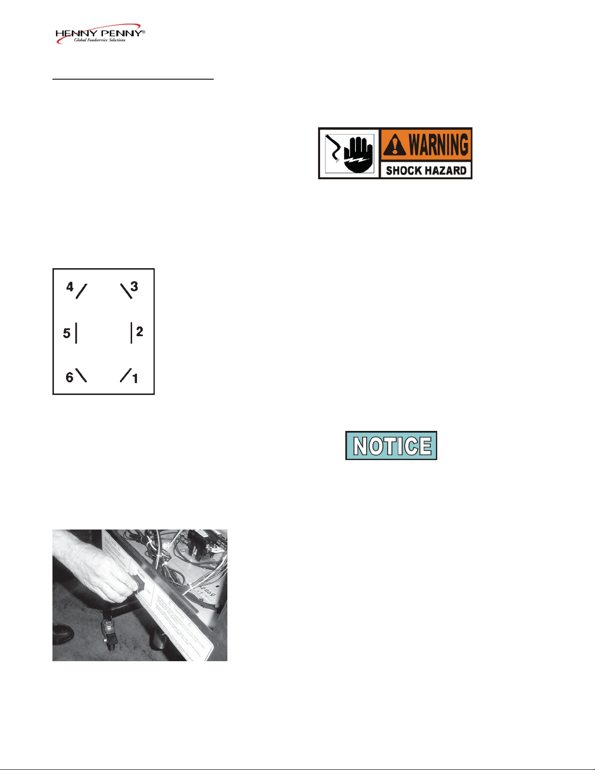
2-6. POWER/PUMP SWITCH
The POWER/PUMP switch is a three way rocker switch with a
center OFF position. With switch in the POWER position, the
fryer operates. With switch in PUMP position, the f lter pump
operates, but the unit will not heat.
To avoid electrical shock or property damage, move the
power switch to OFF and disconnect main circuit
breaker, or unplug cord at wall receptacle.
Checkout
1. Remove control panel.
2. Label and remove wires from the switch.
3. OFF position-should be open circuit anywhere on switch.
4. Power position. Check from: #5 to #6 closed circuit
#l to #2 closed circuit
5. Pump position. Check from: #4 to #5 closed circuit
#3 to #2 closed circuit
Check across the jumpers on the wires of POWER/PUMP
switch. These jumpers have resistors and capacitors which
may be faulty.
Replacement
1. With control panel removed, and wires off of the switch,
push in on tabs on the switch to remove from the panel.
2. Replace with new switch, and reconnect wires to switch
following the wiring diagram.
3. Replace the control panel.
1103 2-5
Page 22
Model 590/592
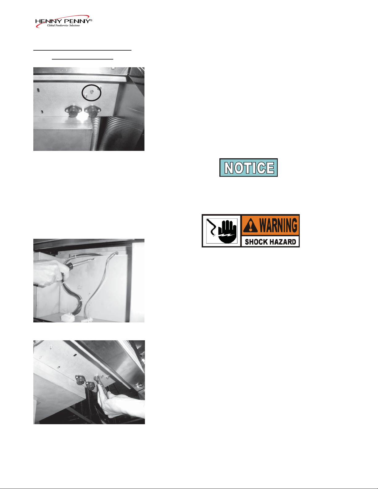
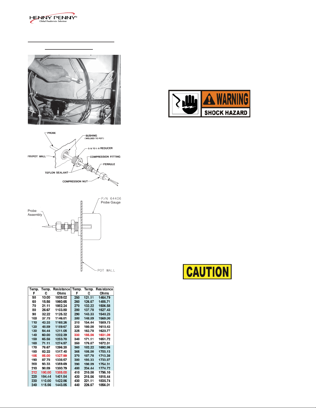
2-7. TEMPERATURE PROBE
REPLACEMENT
The temperature probe relays actual shortening temperature to
the control. If it becomes disabled, “E06” will show in the display. Also, if temperature is out of calibration more than 10°F,
or 10°C, the temperature probe should be replaced. An Ohm
check can be performed also. See chart at end of this section.
1. Remove electrical power supplied to the fryer.
To avoid electrical shock or property damage, move the
power switch to OFF and disconnect main circuit
breaker, or unplug cord at wall receptacle.
2. Drain the shortening from the frypot.
3. Remove the control panel.
4. Using a 1/2” wrench, remove the nut on compression f tting.
Figure 2-1
Figure 2-2
5. Remove the temperature probe from the frypot.
6. Place nut and new ferrule on new temperature probe and
insert temperature probe into compression f tting until it
extends one-half (1/2) inch (1.3 cm) into frypot. Use temp-
erature probe gauge provided in temperature probe kit, to
ensure proper placement in frypot. See Figures 2-1 & 2-2.
7. Tighten hand tight and then a half turn with wrench.
Excess force will damage temperature probe.
8. Connect new temperature probe to PC board and replace
control panel.
9. Replace shortening.
10. Turn power on and check out fryer.
2-6 407
Page 23
Model 590/592
2-8. COMPLETE CONTROL
PANEL-HENNY PENNY
2-9. PRESSURE REGULATION
Should the control panel become inoperative, follow these
instructions for replacing the board.
1. Remove electrical power supplied to the fryer.
To avoid electrical shock or property damage, move the
power switch to OFF and disconnect main circuit
breaker, or unplug cord at wall receptacle.
2. Remove the two screws securing he control panel and lift
panel up and out
3. Unplug the connectors going to the control board.
4. Install a new control panel.
The Henny Penny Fryer uses pressure as one of the components of the cooking process. Once the lid is sealed to the
frypot, and the solenoid valve closes, a deadweight valve maintains the correct pressure in the frypot.
The lid has minimal and limited maintenance and repair procedures, which are addressed in the following sections.
The following is a routine maintenance schedule for the Lid:
Every 90 days
• Clean and reverse the lid gasket
Yearly Inspection
• Check Lid Gasket for splits and tears-replace if necessary
• Check Pressure Pads for wear-rotate if necessary
• Check Cam Slide Guides-replace if worn or broken
• Check Lid Rollers-replace if cracked or damaged
1103 2-7
Page 24
Model 590/592
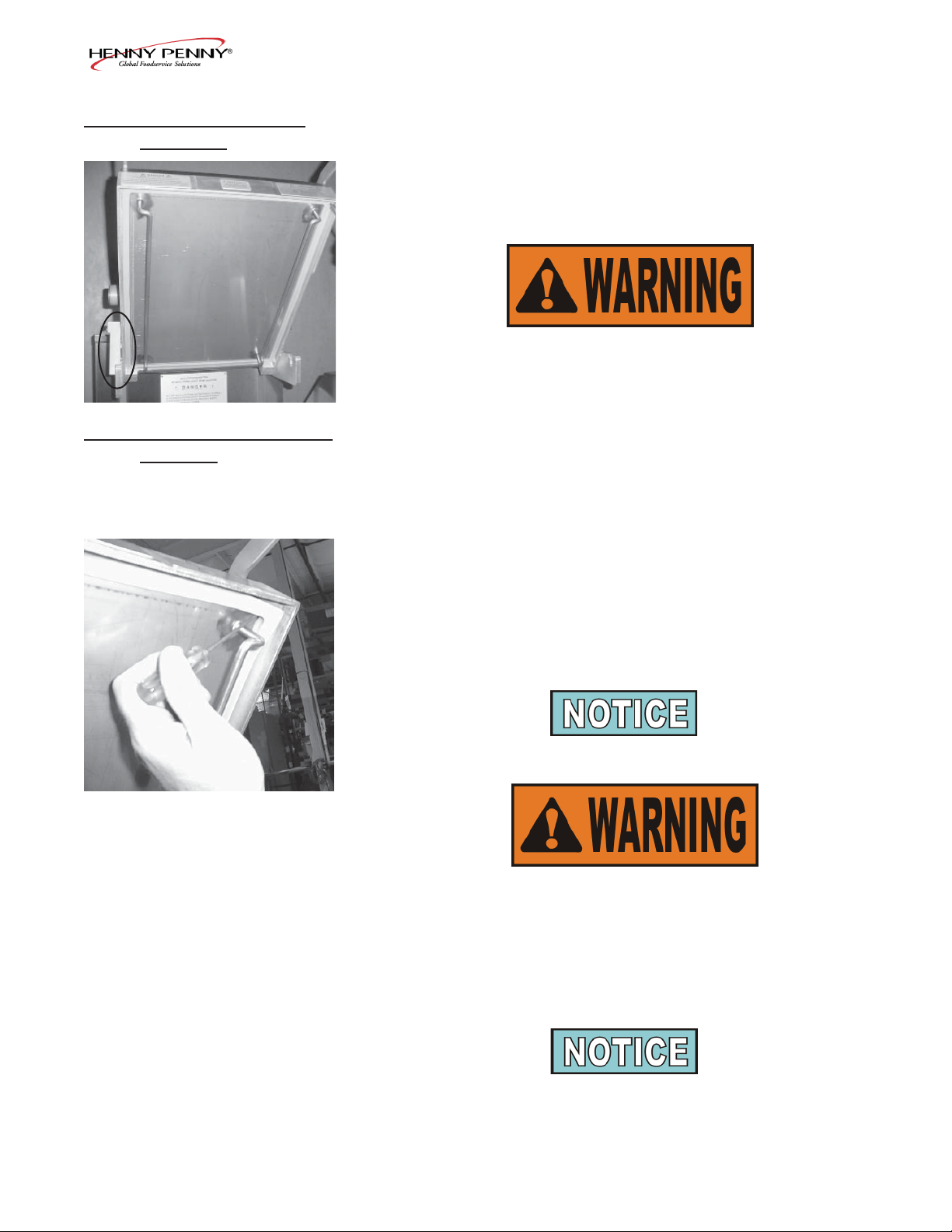
2-10. TILTING THE LID
UPRIGHT
2-11. REVERSING THE LID
GASKET
The Lid Assembly is easily tilted up for cleaning or servicing.
1. Raise the lid and remove racks and carrier.
2. Grasping the lid handle, lift the front of the lid up until it
stops in an upright position.
Be sure the metal arm on the left side of the lid is in the
vertical position holding lid upright, or severe injuries
could result. (See photo at left).
The gray rubber gasket surrounding the inside of the lid is designed to be reversed.
Because of heat expansion and the pressure used for cooking
process, gasket is constantly under extreme stress. Reversing
the lid gasket will help to assure that the fryer will not lose
pressure through leakage.
1. Put the lid in the upright position, as previously described.
2. Using a thin blade screwdriver, pry out the gasket at the
corners. Remove the gasket.
Check the gasket for any tears or nicks. If the gasket is
damaged it needs to be replaced.
Be sure the metal arm on the left side of the lid is in the
vertical position holding lid upright, or severe injuries
could result. (See photo in Tilting Lid Upright section)
3. Clean the gasket and gasket seat with hot water.
4. Rotate the gasket with the opposite side facing out.
Install the 4 corners of the lid gasket. Smooth gasket into
place, working from the corners towards the middle of each
side.
2-8 1103
Page 25

Model 590/592
2-12. LID COUNTERWEIGHT
CABLES
The Lid Counterweight in the back of the fryer balances the
weight of the lid system to allow easier opening and closing of
the lid. The weight has two cables attached to it, and weighs
about 150 lbs. (67.5 Kg).
1. Using a 3/8” socket, remove the nuts securing rear shroud
of the fryer and remove the shroud.
2. Using Phillips-head screwdriver, remove screws securing
the top cap and remove cap.
3. Raise the lid.
4. Unscrew broken cable from the weight assembly and the
bracket attached to the fryer, and remove broken cable.
5. Screw a 5/16” nut on each end of the new cable.
6. Using a wrench, screw new cable into the weight assembly
until tight.
7. Using a 1/2” wrench, tighten nut (already threaded on the
cable) against weight assembly, securing the cable into the
weight assembly.
8. Pull cable over pulley and down behind weight assembly.
9. Insert cable into the hole in the bracket and screw a 5/16”
nut onto end of cable. Tighten cable, by screwing the cable
through this nut until the weight assembly becomes
level.
The safety cable should now have slack in it with the
weight assembly level.
10. Tighten nut against the top of the bracket, securing the
cable.
11. Replace the top cap and rear shroud. The repair is now
complete.
1103 2-9
Page 26

Model 590/592
2-13. PRESSURE PAD
The pressure pads are plastic strips that the lid cam presses
against to seal the lid.
1. Raise the lid.
2. Remove the 4 screws securing the lid cover and remove
cover .
3. Push the lid cam back, off of the pressure pads.
4. Using an Allen wrench, remove the large bolt securing the
pad.
5. Using a Phillips head screw driver, remove the small screw
securing the pad and remove the broken pad.
If the pressure pad is worn, but not broken, it can be
reversed 180 degrees, and the other end of the pad used.
6. Install new pad in reverse order.
2-10 1103
Page 27

Model 590/592
2-14. LID ADJUSTMENT
If steam leaks out from around the lid gasket, the pressure pads
could be worn or broken. If the pressure pad is worn, but not
broken, it can be reversed 180 degrees, and the other end of the
pad used. See Pressure Pad Section.
If steam leaks, check for:
• Pressure pad wear
• Cracked or worn gasket
• Gasket installed improperly
• Fryer operating above 12 psi (827 mbar)
Fryer should be operating at 12 psi, or serious burns
could result.
1103 2-11
Page 28

Model 590/592
2-15. SOLENOID VALVE
This is an electro-mechanical device that causes pressure to be
held in the frypot. The solenoid valve closes at the beginning
of the Cook Cycle and opens automatically at the end of the
Cook Cycle. If this valve should become dirty, or the Tef on
seat nicked, pressure will not build up. The electric fryer uses a
208/240 volt 60 hertz coil (50 hertz internationally).
To avoid electrical shock or property damage, move the
power switch to OFF and disconnect main circuit
breaker, or unplug cord at wall receptacle.
Coil Check Procedure
Remove the solenoid wires from the wire nuts which are found
behind the control panel. Check across wires.
RESULTS
208/240 Volt, 60 Hertz 150 Ohms
208/240 Volt, 50 Hertz 230 Ohms
Replacement
1. Remove the right side panel.
2. Remove the “tru-arc” retaining clip on top of coil housing.
3. Remove the cover.
4. If only the coil is to be replaced, disconnect two coil wires
at wire nuts in the coil housing. Remove coil, insert new
coil, and connect wires at wire nuts. Assemble in reverse
order of disassembly.
The wires may be connected in any order.
2-12 1103
Page 29

Model 590/592
2-15. SOLENOID VALVE
(Continued)
5. If the core-disc assembly is sticking due to buildup of
shortening, breading, and food particles, proceed with the
following steps:
a. Unscrew the solenoid bonnet assembly from solenoid
valve body.
b. Remove solenoid bonnet assembly and bonnet gasket.
c. Remove the core-disc assembly, core spring retainer,
and the core spring.
d. Wash all these parts in hot water.
If Tef on seals need to be replaced, proceed to Step 6;
otherwise, assemble in reverse order of disassembly.
Assemble valve core and blade with smooth side and
rounded edge of blade toward the disc spring guide.
6. Repair kit, Part No. 17120, is available if any of the seals
must be replaced. If one seal is defective, replace all seals.
Solenoid body must be removed from the fryer for replace
ment of seals. Continue on to step 7.
7. Loosen wires on the strain relief and pull the wires through
the relief.
8. With the bonnet assembly and core-disc assembly removed,
disconnect the two nut f ttings. One connects the solenoid
valve to the deadweight, the other is attached to the
condensation tank.
9. Remove the elbows from the solenoid valve.
10. Remove the two adapter screws which attach the pipe
adapter to the solenoid valve body.
11. Remove the disc spring, guide, and Tef on seat.
12. Clean the valve body.
1103 2-13
Page 30

Model 590/592
2-15. SOLENOID VALVE
(Continued)
2-16. DEADWEIGHT VALVE
13. Wet “O” ring around seat with water and insert O-ring
assembly (f at side f rst) in valve through “IN” side of
body. Use an eraser end of pencil and press in the Tef on
seal until it snaps into place. Be careful not to mar or nick
the seat.
The smallest nick can cause a pressure leak. Replace all
O-ring seals that are in the parts kit and reassemble the
valve.
14. If the complete valve is to be replaced, follow steps 1, 2, 3,
4, 5, 7, 8 and 9 in this section.
Deadweight valve
DO NOT ATTEMPT TO REMOVE DEADWEIGHT
CAP WHIILE FRYER IS OPERATING. SEVERE
BURNS OR OTHER INJURIES WILL RESULT.
The operating valves are located behind the lid. The valve, left of
the pressure gauge, is a 14 1/2 lb. (999 mbar) safety relief valve,
and the one on the right is the deadweight valve.
Valves are working properly , when the pointer on the gauge is
in the “OPERATING ZONE” (green area). The gauge pointer
should not normally exceed the operating zone. If the pressure
builds to 14 1/2 lbs.(999 mbar), the safety relief valve will open
to release steam pressure from inside frypot.
2-14 1103
Page 31

2-16. DEADWEIGHT VALVE
(Continued)
ORIFICE CAP DEADWEIGHT
Model 590/592
DO NOT PULL THE RING ON THE SAFETY
RELIEF VALVE. HOT STEAM WILL BE
RELEASED AND SEVERE BURNS WILL RESULT.
1. At the end of each day’s usage of the fryer, the deadweight
valve must be cleaned. The fryer must be OFF and pressure
released. Open the lid and then remove the deadweight
valve cap and deadweight.
2-17. REMOVAL & CLEANING
OF SAFETY RELIEF
VALVE
SAFETY RELIEF VALVE
Failure to clean the deadweight assembly daily could
result in the fryer building too much pressure. Severe
injuries and burns could result.
2. Wipe both the cap and weight with a soft cloth. Make
certain to thoroughly clean inside cap, the weight seat, and
around deadweight orif ce.
3. Dry the parts and replace immediately to prevent damage
or loss.
The safety relief valve should be cleaned once a year.
DO NOT ATTEMPT TO REMOVE SAFETY VALVE
WHILE FRYER IS OPERATING, OR SEVERE
BURNS OR OTHER INJURIES WILL RESULT.
1. Remove pressure gauge.
1103 2-15
Page 32

Model 590/592
2-17. REMOVAL & CLEANING
OF SAFETY RELIEF
VALVE (Continued)
2. Use a wrench to loosen the valve from the pipe tee, turn
counterclockwise to remove.
3. Clean the inside of the pipe tee with hot water.
Turn the safety relief valve towards the rear of the fryer
when reinstalling safety relief valve.
4. Immerse the safety relief valve in a soapy water solution
for 24 hours. Use a 1 to 1 dilution rate. The valve cannot
be disassembled. It is factory preset to open at 14 1/2
pounds of pressure. If it does not open or close, it must
be replaced.
DO NOT DISASSEMBLE OR MODIFY THIS VAL VE.
TAMPERING WITH THIS VALVE COULD CAUSE
SERIOUS INJURIES AND WILL VOID AGENCY
APPROVALS AND APPLIANCE W ARRANTY.
2-18. PRESSURE GAUGE
Adjusting
Screw
Calibration Steps
The pressure gauge can be recalibrated should it be out of
adjustment.
1. Remove the rim and glass.
2. If the indication hand shows a pressure or vacuum reading
when it should stand at “0”, turn the recalibrator screw
in the same direction in which the indicating hand is to
be moved until the hand stands a proper “0” position.
3. Replace the rim and glass.
Cleaning Steps
1. Remove the gauge and check inside the pipe f ttings from
deadweight body. Make certain f ttings are clean and open.
2. Clean and reinstall the gauge.
2-16 1103
Page 33

Model 590/592
2-19. CONTACTORS
Primary
Heat
30 31 32
The electric fryer requires two switching contactors: a primary
and a heat contactor. The primary contactor energizes (contacts
close) any time the POWER/PUMP switch is in the POWER
position, and the temperature of the shortening is below 420° F
( 215° C). The high limit cuts power at the primary contactor
if the temperature of the shortening is above 420
The primary contactor supplies power to one side of the heat
contactor.
The heat contactor is controlled by the computer controller.
When the controller calls for heat, the heat contactor applies
power to one side of the heating elements. When the heat contactor and primary contactor are energized (contacts closed) the
electric heating elements heat the shortening.
The photo shows a mercury heat contactor, but CE coun-
tries will have an electromechanical heat contactor.
Checkout
1. Remove electrical power supplied to the fryer.
° F ( 215° C).
To avoid electrical shock or property damage, move the
power switch to OFF and disconnect main circuit
breaker, or unplug cord at wall receptacle.
2.
Remove the control panel.
3. Label and remove wires from contactors and perform a
34 35 36
1103 2-17
check on both contactors as follows:
Test Points Results
From 23 to 29
From 24 to 28 open circuit
From 25 to 27 open circuit
From 30 to 34 open circuit
From 31 to 35 open circuit
From 32 to 36 open circuit
From 33 to 37 ohm reading 1700
From 22 to 26 ohm reading 415
open circuit
Page 34

2-19. CONTACTORS
(Continued)
Model 590/592
To avoid electrical shock, make connections before
applying power, take reading, and remove power
before removing meter leads. The following checks
are performed with the wall circuit breaker closed and
the main power switch in the ON position.
4. With power reapplied and in a heat-up mode, check the
power going to both contactor coils. This is to be sure
power is going to the contactors.
If no voltage is found going into the primary contactor coil,
check wiring, high limit, and drain switch. If no voltage at heat
contactor coil, check wiring and connections at PC board.
Replacement
If either contactor proves defective, replace as follows:
To avoid electrical shock or property damage, move the
power switch to OFF and disconnect main circuit
breaker, or unplug cord at wall receptacle.
1. Label and remove only those wires directly connected to
the contactor being replaced.
Hint: Removing the left side panel may be helpful in
replacing the heat contactor.
2. Remove the mounting screws on the base plate of the
primary contactor and remove contactor. Proceed to step 5.
3. Remove the screws securing the mercury contactor bracket
to the mounting plate and remove bracket and contactor.
4. Remove the screws securing the contactor to the bracket
and remove contactor from bracket.
5. Install new contactor in reverse order.
6. Install control panel and reconnect power to the fryer and
test for proper operation.
2-18 1103
Page 35

Model 590/592
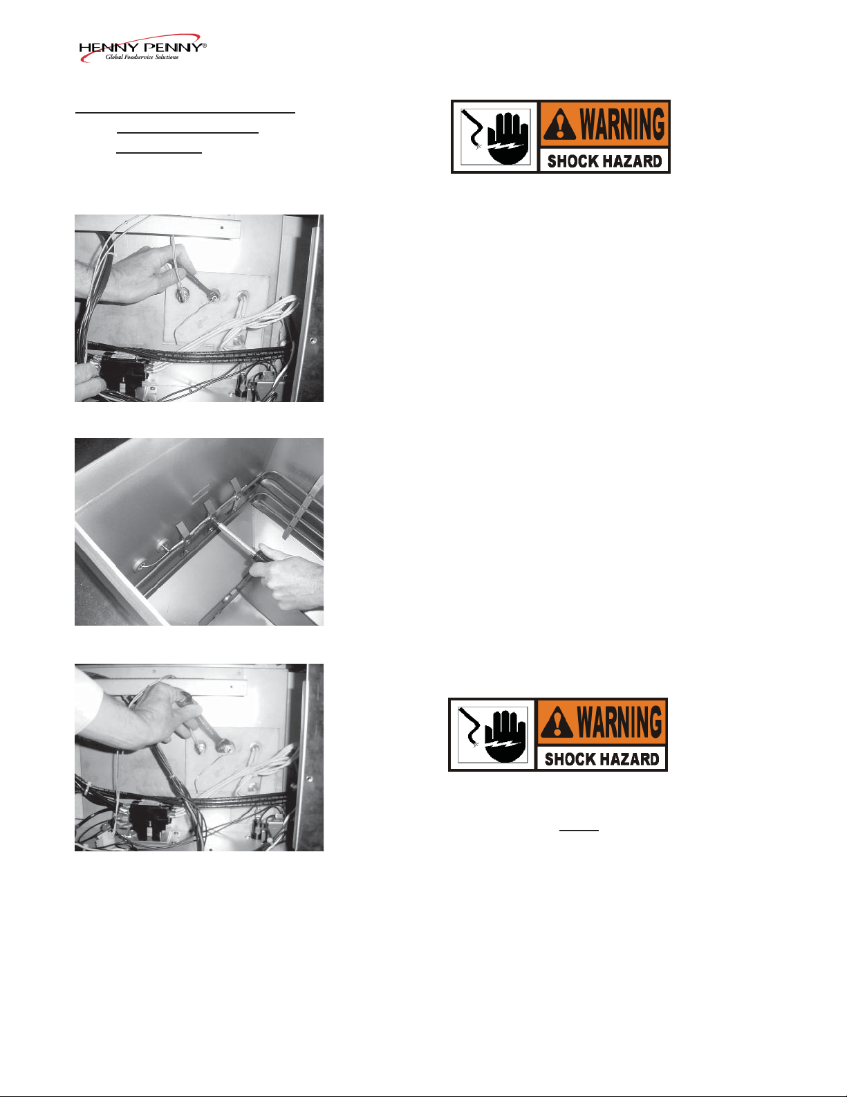
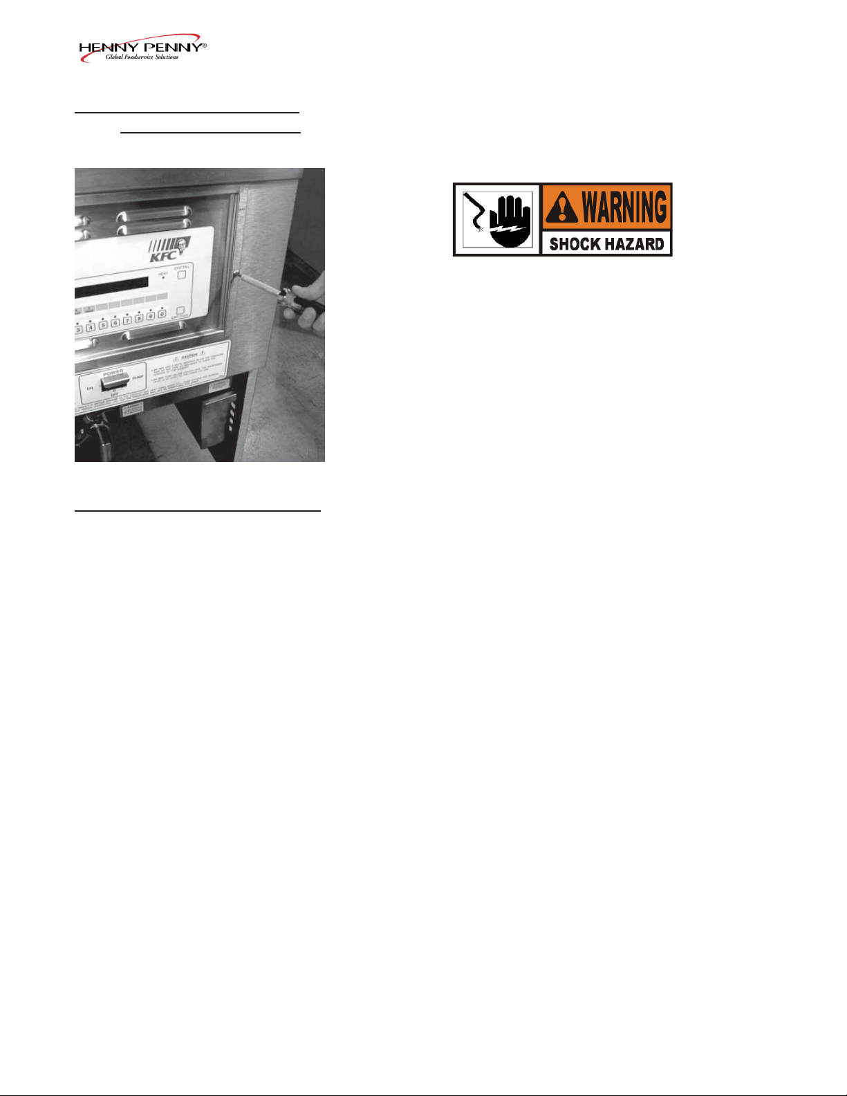
2-20. HEATING ELEMENTS
The electric model fryer uses 2 heating elements.
Heating elements are available in 208, 220/240, 380 and
415 volts. Check the data plate, on the shroud behind the
lid, to determine the correct voltage elements.
1. Remove the electrical power supplied to the unit.
To avoid electrical shock or property damage, move the
power switch to OFF and disconnect main circuit
breaker, or unplug cord at wall receptacle.
2. Remove the control panel.
3. Remove both side panels.
4. Remove upper screws and loosen the lower screws, to the
front control shroud, and hinge it down. (See photo at left)
To avoid electrical shock, make connections before
applying power, take reading, and remove power
before removing meter leads. The following checks are
performed with the wall circuit breaker closed and the
main power switch in the ON position.
5. Perform an amp check on one heating element at a time
with the wires connected to the contactors. The 2 heaters
actually have 3 small heating elements on the inside of the
outer plate. It is important to check between the correct
wires to obtain the accurate amp reading. The wires are
labeled for your convenience.
Wires Power Voltage Amperage
L1-L3 8500W 208V 47.8
L3-L2 8500W 208V 47.9
L2-L1 8500W 208V 48.0
L1-L2 8500W 240V 39.4
L3-L2 8500W 240V 40.1
L2-L1 8500W 240V 39.9
1103 2-19
Page 36

Model 590/592
2-20. HEATING ELEMENTS
(Continued)
Replacement
1. Drain the shortening.
2. Remove the high limit bulb holder from the heating
element inside the frypot.
3. Disconnect the heating element wires from the contactors.
Label each so it can be replaced in the same position on the
new element.
4. Remove the heat contactor, as described in Contactors
Section, to access the left side element nuts.
5. Loosen the screws on the element spreaders.
6. Slide element spreaders to the center of the heating element.
7. Using a 7/8” crowsfoot, remove the brass nuts and
washers which secure the ends of the elements through the
frypot wall.
8. Remove the heating elements from the frypot as a group by
lifting the far end, and sliding them up and out towards the
rear of the frypot.
Always install new rubber O-rings (2) when installing
heating elements.
9. Install new heating elements with new rubber O-rings
mounted on terminal ends, and spreaders loosely
mounted in the center of the stacked elements.
10. Replace the heating elements, terminal end f rst at
approximately 45º angle, slipping the terminal ends through
the front wall of the frypot.
2-20 1103
Page 37

Model 590/592
2-20. HEATING ELEMENTS
(Continued)
10. Replace the brass nuts and washers on the heating element
terminals. Tighten the brass nuts to 30 foot lbs of torque.
11. Replace heat contactor.
12. Move the element spreaders from the center of the ele
ment, into a position which will spread each element apart
evenly on all four sides, and tighten.
13. Replace the high limit bulb holder on the top element, and
position the bulb between the top and second element mid way from side to side, and tighten screw which holds the
bulb in place.
14. Reconnect the wires to the appropriate terminal as labeled
when they were removed.
15. Replace the front control shroud and control panel.
16. Replace side panels.
17. Connect the power cord to the wall receptacle or close
wall circuit breaker.
Heating elements should never be energized without
shortening in the frypot, or damage to elements could
result.
1103 2-21
Page 38

Model 590/592
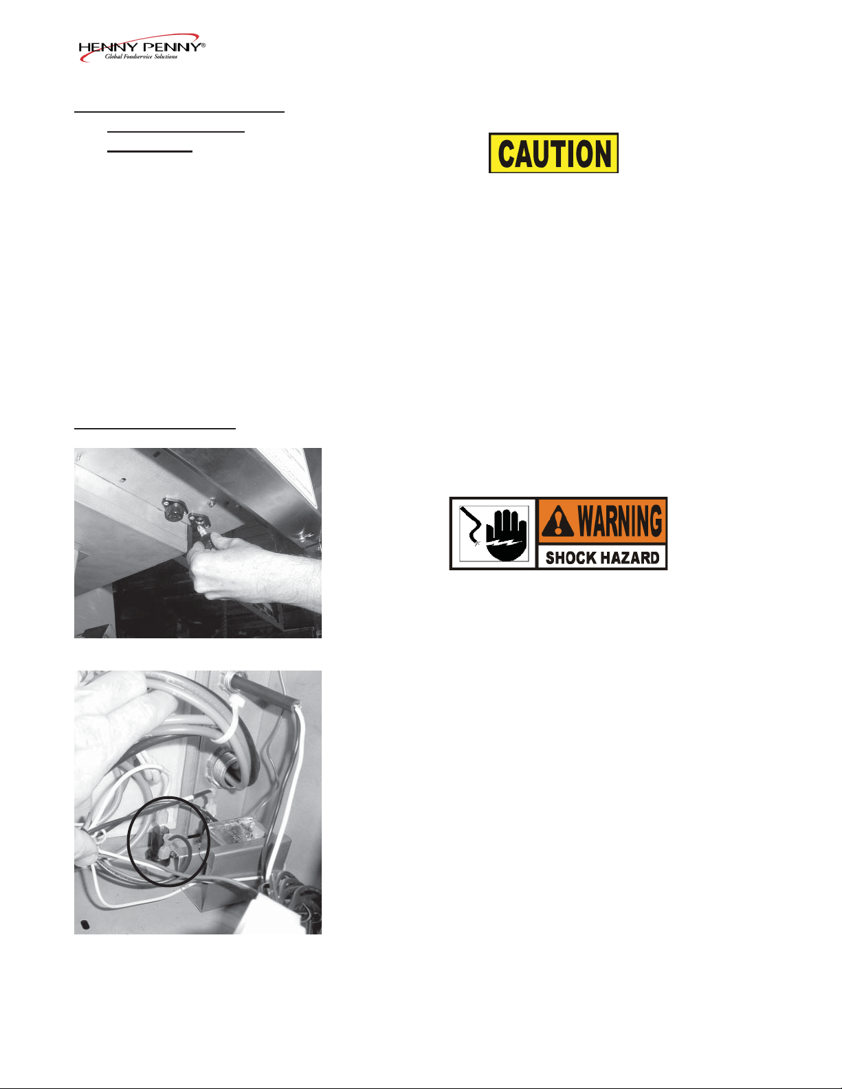
2-21. DRAIN MICROSWITCH
Upon pulling out on the drain handle, the microswitch should
be activated and the unit will not heat, but when the handle is
pushed back, the unit should operate properly. The bracket on
the microswitch is slotted so it can be adjusted backward or
forward.
1. Remove electrical power supplied to the unit.
To avoid electrical shock or property damage, move the
power switch to OFF and disconnect main circuit
breaker, or unplug cord at wall receptacle.
2. The following check should be made to determine if the
drain switch is defective.
a. Remove bracket from the unit.
b. Remove wires from the switch.
c. Check for continuity across the two outside terminals
on the drain switch. If circuit is open, the Drain Switch
is bad. The circuit should only be opened by pressing
on the actuator of the Drain Switch.
1/8” (4 mm) Gap
3. To replace switch, remove switch from the bracket, and
install switch in reverse order.
4. Test to see if drain valve handle actuates the switch. The
gap between the drain switch and the shaft should be no
more than 1/8” (3 mm).
HINT: Listen for audible click of switch while pulling drain
valve handle.
2-22 1103
Page 39

Model 590/592
2-22. DRAIN VALVE
AND EXTENSION
The drain valve opens when the drain valve handle is pulled
out and drains the shortening out of the pot.
Replacement
1. Using a 3/8” socket, remove the nuts securing the drain
switch bracket, and pull the bracket from the studs.
2. Remove the nut securing the drain handle and pull the
handle from the drain valve.
3. Using a large adjustable wrench, unscrew the drain valve
and extension from the unit.
4. Replace the drain valve and extension.
5. Replace the drain switch bracket.
6. Adjust the microswitch to be no more than 1/8” (3 mm)
from the shaft of the drain valve.
HINT: Listen for audible click of switch while pulling drain
valve handle.
1103 2-23
Page 40

Model 590/592
2-23. NYLATRON STRIPS
REPLACEMENT
1. Raise the lid and remove the retention ring from one end of
the lid pin.
2. Slide the lid pin from unit.
3. Lift the lid from unit.
The lid weighs 80 lbs (36 kg). Take care when lifting lid
to prevent personal injury.
4. Using a 3/8” socket, remove the nuts securing the rear
shroud and remove shroud.
5. Using a Phillip’s-head screwdriver, remove the screws
securing the top cap and remove top cap.
6. Remove the bolts securing the nylatron strips to the weight
assembly and remove strips from weight assembly.
7. Using a Phillip’s-head screwdriver, remove the screws
securing the front shroud.
8. Unfasten the exhaust hose from the hose clamp.
2-24 1103
Page 41

Model 590/592
2-23. NYLATRON STRIPS
REPLACEMENT
(Continued
9. Lift the front shroud up and out, over the arm of the lid.
10. Thread the new nylatron strip through the track in the front
shroud.
11. Lining up the holes in the strips, f t the front shroud back
over the lid arms.
12. Secure the strips to the weight assembly.
13. Replace back shroud, top cap, and lid, and replacement is
complete.
1103 2-25
Page 42

Model 590/592
SN: AC0608030 & below
2-26 1203
Page 43

Model 590/592
SN: AC0608031 & above
707 2-27
Page 44

Model 590/592
SN: AC0608030 & below
2-28 1203
Page 45

Model 590/592
SN: AC0608031 & above
707 2-29
Page 46

Model 590/592
SN: AC0608030 & below
2-30 1203
Page 47

Model 590/592
SN: AC0608031 & above
707 2-31
Page 48

Model 590/592
SN: AC0608030 & below
2-32 1203
Page 49

Model 590/592
SN: AC0608031 & above
707 2-33
Page 50

Model 590/592
SN: AC0608030 & below
2-34 1203
Page 51

Model 590/592
SN: AC0608031 to 10-4-07
1107 2-35
Page 52

Model 590/592
10-4-07 & After
2-36 1107
Page 53

Model 590/592
1107 2-37
Before 10-4-07
Page 54

Model 590/592
2-38 1107
10-4-07 & After
Page 55

Model 590/592
SECTION 3. PARTS INFORMATION
3-1. INTRODUCTION This section lists the replaceable parts of the Henny Penny
Model 590 fryer.
3-2. GENUINE PARTS Use only genuine Henny Penny parts in your fryer. Using a
part of lesser quality or substitute design may result in damage
to the unit or personal injury.
3-3. WHEN ORDERING PARTS Once the parts that you want to order have been found in the
parts list, write down the following information:
Item Number 2
Part Number 16738 Example:
Description High Limit
From the data plate, list the following information:
Product Number 01100
Serial Number 0001 Example:
Voltage 208
3-4. PRICES Your distributor has a price parts list and will be glad to inform
you of the cost of your parts order.
3-5. DELIVERY Commonly replaced items are stocked by your distributor and
will be sent out when your order is received. Other parts will
be ordered, by your distributor, from Henny Penny Corpora tion. Normally, these will be sent to your distributor within
three working days.
3-6. WARRANTY All replacement parts (except lamps and fuses) are warranted
for 90 days against manufacturing defects and workmanship.
If damage occurs during shipping, notify the carrier at once so
that a claim may be properly f led. Refer to warranty in the
front of this manual for other rights and limitations.
Recommended replacement parts, stocked by your distributor,
3-7. RECOMMENDED
are indicated with √ in the parts lists. Please use care when
ordering recommended parts, because all voltages and varia-
SPARE PARTS FOR
DISTRIBUTORS
tions are marked. Distributors should order parts based upon
common voltages and equipment sold in their territory.
106 3-1
Page 56

Model 590/592
3-8. INDEX OF PARTS LIST ILLUSTRATIONS
Title Fig. No. Page No.
FRAME & COVER ASSEMBLY.................................................................. 3-1 3-3
ELEMENT ASSEMBLY ............................................................................... 3-2 3-5
COUNTERWEIGHT SYSTEM .................................................................... 3-3 3-6
LID & COVER ASSEMBLY ......................................................................... 3-4 3-7
STEAM BOX & HOSE ASSEMBLY ........................................................... 3-5 3-9
DEADWEIGHT & SOLENOID ASSEMBLY .............................................. 3-6 3-10
SOLENOID VALVE ASSEMBLY ................................................................ 3-7 3-12
FAST READY PARTS ................................................................................... 3-8 3-14
CONTROL PANEL ASSEMBLY .................................................................. 3-9 3-16
BEHIND CONTROL PANEL COMPONENTS ........................................... 3-10 3-17
FILTER PUMP ASSEMBLY (SN: LG012JC & BELOW) ........................... 3-11A 3-18
FILTER PUMP ASSEMBLY (SN: LG013JC & ABOVE) ............................ 3-11B 3-20
DRAIN VALVE & DRAIN SWITCH ASSEMBLIES .................................. 3-12 3-22
DRAIN PAN & FILTER ASSEMBLY .......................................................... 3-13 3-23
CARRIER, RACKS & JUNCTION BOX ASSY .......................................... 3-14 3-25
3-2 1203
Page 57

Model 590/592
FIGURE 3-1. FRAME & COVER ASSEMBLY
110 3-3
Page 58

Model 590/592
Figure &
Item No. Part No. Description Qty.
3-1 FRAME & COVER ASSEMBLY
1 39796 WELDMENT – CONTROL PANEL FRONT ........... 1
2 53669 GUARD – POWER SWITCH ................................... 1
3 29898 SWITCH – POWER .................................................. 1
4 54225 1” INSERT – LEG MACHINED ............................... 4
5 35154 CASTER, SWIVEL 4” .............................................. 2
6 37246 CASTER W/BRAKE & SWIVEL LOCK ................. 2
7 SC03-005 SCREW - - #8 x 1/2” PH PHD ................................. 4
8 66934 SIDE PANEL – RIGHT ............................................. 1
9 SC01-215 SCREW - 5/16-18 x 2.5” HEX HD BOLT ................ 4
10 37291 REAR SHROUD – ACCESS ASSEMBLY ............... 1
11 35726 TOP COVER – REAR SHROUD.............................. 1
12 66933 SIDE PANEL – LEFT ................................................ 1
12 14457 KIT - SOUND DEADENING ................................... 1
13 36337 DOOR – ACCESS ..................................................... 1
14 SC02-023 SCREW - #8-B x 3/8” PH THD SS ........................... 5
15 62085 REAR SHROUD ....................................................... 1
recommended parts
3-4 110
Page 59

Model 590/592
Figure &
Item No. Part No. Description Qty.
3-2 ELEMENT ASSEMBLY
1 SC01-083 SCREW, (#10-32 x 1/2 PH FHD)
......................................... As Required
2 35101 SUPPORT, ELEMENT - LONG ................................ 5
3 35100 SUPPORT, ELEMENT - SHORT ............................... 5
4 SC01-074 SCREW, (#10-32 x 1/2 PH THD S)
..................................... As Required
5 35435 BRACKET, HI LIMIT PROBE .................................. 3
6 35462 BRACKET, HI LIMIT PROBE .................................. 3
7 35234 HEAT ELEMENT ASSEMBLY, 8.5 KW 208V ......... 2
35598 HEAT ELEMENT, 8.5 KW 240V .............................. 2
48367 HEAT ELEMENT, 230 V(Int’l Only) ........................ 2
36290 HEAT ELEMENT, 220 V(Int’l Only) ........................ 2
8 16855 SEAL, O-RING .......................................................... 4
9 WA01-005 WASHER, (5/8 DIA. TYPE A - SERIES N) .............. 8
10 NS01-017 NUT, (5/8-18 B HEX) ................................................ 4
recommend. parts
106 3-5
Page 60

Model 590/592
Figure &
Item No. Part No. Description Qty.
3-3 COUNTERWEIGHT SYSTEM
1 35026 ARM, LID SUPPORT ........................................................ 2
2 35207 CABLE ............................................................................... 2
3 NS01-025 NUT, HEX 5/16-18 SS ....................................................... 10
4 LW01-010 WASHER, 3/8 SPLIT RING SS......................................... 10
5 35092 CARRIAGE ....................................................................... 1
6 SC01-069 SCREW, 3/8-16 X 1-1/2 HEX HD S2P ............................. 8
7 36839 SLIDE ................................................................................. 2
8 SC01-042 SCREW, 3/8-16 X 1 HEX C .............................................. 2
9 36625 WELD ASSEMBLY, C/W CARRIAGE ............................ 1
10 36627 COUNTERWEIGHT BAR ................................................ 7
11 36626 SPACER, C/W FRAME ..................................................... 2
12 37362 WHEEL, CARRIAGE ....................................................... 4
13 37363 SPACER, CARRIAGE WHEEL ........................................ 4
14 37364 SPINDLE ........................................................................... 4
15 SC01-081 SCREW, 3/8-24 X 3/4 HEX HD SS ................................... 4
16 35962 BRACKET/WHEEL ASSY. ............................................... 2
17 36561 BRACE, TOP FRAME....................................................... 1
18 35964 PLATE, SUPPORT PULLEY ............................................ 4
19 SC01-132 SCREW, CAP, SOC HD, 1/2-20 X 5/8 .............................. 8
recommended parts
3-6 110
Page 61

Model 590/592
3-4. LID & COVER ASSEMBLY
407 3-7
Page 62

Model 590/592
Figure &
Item No. Part No. Description Qty.
3-4 LID & COVER ASSEMBLY
1 35792 LID INSTRUCTION LABEL ........................................... 1
2 35675 FILLER-LID...................................................................... 2
3 35243 COVER-MAIN LID .......................................................... 1
4 35413 PLATE-TRIP ..................................................................... 1
5 52627 PRESSURE PAD ASSY. .................................................. 2
6 49852 BUSHING-PRESSURE PAD .......................................... 2
7 SC01-204 SCREW 1/4-20X1.00 SOCK BUTT ................................. 2
8 49962 PLATE, SHIM ASSY. (L.H.) ............................................. 1
9 49890 PLATE, CAM GUIDE (L.H.)............................................ 1
10 35359 SLIDE (6”) ........................................................................ 2
11 RR01-004 RING, RETAINING ½” .................................................... 1
12 WA01-020 WASHER, LID STOP ....................................................... 1
13 51531 CAST, LID STOP .............................................................. 1
14 SC01-074 SCREW, #10-32 x ½ PH THD SS ..................................... 8
15 35223 WASHER, SPECIAL ......................................................... 1
16 35227 ROLLER, LINKAGE SHAFT .......................................... 2
17 35339 GUIDE, HANDLE SIDE .................................................. 2
18 SC01-062 SCREW, #6-32 x 3/8 PH FH ............................................. 4
20 SC01-041 SCREW, 5/16-18 x 1.00 HEX HD C ................................. 2
21 36285 WELDMENT, HANDLE TAP PLATE ............................. 1
23 34526 GASKET, LID - SN: AC0712021 & below ...................... 1
23 66620 GASKET, LID - SN: AC0712022 & above ...................... 1
24 35945 PIN, LID SUPPORT .......................................................... 1
25 52497 LATCH ASSEMBLY, COATED ....................................... 1
26 52498 LATCH SPRING ............................................................... 1
27 59169 LATCH BRACKET, LID (MACHINED) ......................... 1
28 51707 LATCH BRACKET, LID .................................................. 2
29 LW02-006 LOCKWASHER, LATCH ................................................. 2
30 SC01-248 SCREW, LATCH, 10-32 x 1.25 PH THD SS .................... 2
31 35032 PIN, LID SUPPORT .......................................................... 1
32 RR01-010 RING, RET. 3/4 SHAFT SS .............................................. 2
33 36312 WASHER, LID HINGE..................................................... 2
34 51697 PIN, LID HINGE............................................................... 1
35 49895 PLATE, CAM GUIDE (R.H.) ........................................... 1
36 49963 PLATE SHIM ASSEMBLY (R.H.) ................................... 1
37 SC01-146 SCREW, 1/4-20 x 3/4 HEX HD SS ................................... 2
38 52477 LIFT, LID .......................................................................... 1
39 35465 CAM SLIDE FILLER ....................................................... 2
41 SC01-195 SCREW, 8-32 x 1-7/16 PH FHD S .................................... 12
42 OR01-005 O-RING, 5/16 x 1/16 DIA. ................................................ 12
43 LW01-002 LOCKWASHER, SPLIT RING 1/4 S ............................... 12
44 NS01-008 NUT, 8-32 HEX ................................................................. 12
45 79418 ASSY - 590 REBUILT LID ............................................... 1
recommended parts/* not shown
3-8 110
Page 63

Model 590/592
Figure &
Item No. Part No. Description Qty.
3-5 STEAM BOX & HOSE ASSY
1 35686 TUBE, DW TO EXHAUST STACK SS ............................ 1
2 MS01-297 HOSE CLAMP, SS - .500 – 1.062 DID ............................. 4
3 35693 TUBE, EXHAUST CONNECT ......................................... 1
4 35696 WELDMENT, STEAM EXHAUST BOX LID ................. 1
5 SC02-041 SCREW, #8-18 X 7/16 PH IND XTRNL TRX ................. 4
6 66732 WELDMENT, STEAM EXHAUST BOX ......................... 1
7 82517 HOSE, CONDENSATE (SN: AC0903045 & ABOVE) .... 1
7 66723 TUBE, CONDENSATE (SN: IG048JC - AC0903044) ..... 1
7 62211 TUBE, CONDENSATE (SN: IG047JC & BELOW) ......... 1
8 69263 RESTRICTOR ................................................................... 1
9 MS01-315 HOSE CLAMP, ½ X 1-3/4 SS ........................................... 2
10 NS01-011 NUT, (#10-32 HEX) ........................................................... 1
11 36851 BRACKET, HOSE ............................................................. 1
12 21877 TUBING, STEAM EXHAUST .......................................... 4
13 71409 CONDENSATE PAN WELDMENT ................................. 1
14* EF02-118 2 HOLE CONDUIT CLAMP 1” EMT (cond. hose) .......... 1
* not shown
110 3-9
Page 64

Model 590/592
3-6. DEADWEIGHT & SOLENOID ASSEMBLY
3-10 1203
Page 65

Model 590/592
Figure &
Item No. Part No. Description Qty.
3-6 DEADWEIGHT & SOLENOID ASSY
1 16910 PRESSURE GAUGE.................................................. 1
2 59742 RELIEF VALVE ASSY .............................................. 1
3 FP01-127 ELBOW, STREET, ½ X ½, 90 DEGREE .................. 1
4 FP01-063 REDUCER, ½ NPT M TO ¼ NPT F .......................... 1
5 FP01-011 PIPE TEE, ½ NPT 304 SS .......................................... 2
6 FP01-028 NIPPLE, CLOSE ½ NPT ............................................ 2
7 17407 CONNECTOR, ½ MALE ELBOW ........................... 3
8 16817 FITTING, SLEEVE TEFLON ....................................
As Required
9 16809 NUT FITTING ............................................................ As Required
10 56307 CAP, DEAD WEIGHT .............................................. 1
11 16902 SEAL “O” RING ........................................................ 1
12 16903 DEADWEIGHT - 12 PSI ........................................... 1
12 65449 DEADWEIGHT - 3 PSI ............................................. 1
12 81343 DEADWEIGHT - 11 PSI............................................ 1
13 16918 ORIFICE, 12 PSI ........................................................ 1
14 16852 BODY, VALVE ........................................................... 1
15 35686 TUBE, DW TO EXHAUST STACK .......................... 1
16 35817 PIPE NIPPLE, ½ X 2 ¼ SS ........................................ 1
17 16804 UMBRELLA GROMMET ......................................... 1
18 35200 UMBRELLA GRAMMET ......................................... 1
19 35474 PIPE NIPPLE, ½ X 2 .................................................. 1
20 FP01-066 COUPLING, ½ NPT SS ............................................. 1
21 16807 FITTING CONNECTOR, MALE .............................. 1
22 35147 TUBE, STEAM EXHAUST - UP .............................. 1
23 18721 VALVE, SOLENOID 208-240V, 60 Hz ..................... 1
23 18724 VALVE, SOLENOID 208-240V, 50 Hz ..................... 1
24 16808 FITTING SLEEVE, STEEL ....................................... 1
recommended parts
110 3-11
Page 66

Model 590/592
3-7. SOLENOID VALVE ASSEMBLY
3-12 1005
Page 67

Model 590/592
Figure &
Item No. Part No. Description Qty.
3-7 SOLENOID VALVE ASSEMBLY
1 18721 VALVE, SOLENOID 208-240V, 60 Hz .......................... 1
1 18724 VALVE, SOLENOID 208-240V, 50 Hz .......................... 1
2* 17120 KIT, SOLENOID VALVE REPAIR ........................... 1
3 17101 CLIP, RETAINER ...................................................... 1
4 17109 RETAINER, SPRING ................................................ 1
5 17110 SPRING, CORE ......................................................... 1
6 17111 CORE, DISC ASSEMBLY ........................................ 1
7 17112 GASKET, BONNET .................................................. 1
8 17114 SEAT, TEFLON ......................................................... 1
9 17115 GUIDE, DISC SPRING ............................................. 1
10 17116 SPRING, DISC .......................................................... 1
11 17117 RING, SPRING RETAINER ..................................... 1
12 17122 SEAT, O-RING SEAL ............................................... 1
13 17102 PLATE, SOLENOID NAME ........................................... 1
14 17103 COVER, COIL HOUSING .............................................. 1
15 17104 WASHER, COIL .............................................................. 2
16 17105 YOKE, COIL ................................................................... 1
17 18706 COIL, 208-240V, 60 Hz ................................................... 1
17 18726 COIL, 208-240V, 50 Hz ................................................... 1
18 17123 HOUSING, COIL ............................................................ 1
19 17108 BONNET, SOLENOID .................................................... 1
20 17113 BODY, SOLENOID VALVE ........................................... 1
21 17118 ADAPTER, PIPE ............................................................. 1
22 SC01-132 SCREW, ADAPTER ........................................................ 2
recommended parts
* not shown
106 3-13
Page 68

Model 590/592
2
1
14
13
3
12
11
4
5
6
10
7
9
8
3-8. FAST READY PARTS
3-14 1203
Page 69

Model 590/592
Figure &
Item No. Part No. Description Qty.
3-8 FAST READY PARTS
1 23806 ASSY - CONTROL PANEL CE- 592 ........................ 1
1 23805 ASSY - STUD-CONTROL - 592 ............................... 1
2 51292 DECAL - FAST CONTROL ....................................... 1
3 54085 LIGHT - CE INDICATOR, GREEN .......................... 3
3 16624 LIGHT - INDICATOR, RED ...................................... 3
4 16640 SWITCH MAIN ASSY - 4 PDT ................................. 1
5 48369 SWITCH COVER ...................................................... 1
6 18450 GUARD - SWITCH FRYER ...................................... 1
7 NS03-018 NUT - 3/4-32 JAM ..................................................... 2
8 NS02-007 NUT HEX KEPS #8-32 C .......................................... 10
9 EF02-002 BUSHING 33/64 P ..................................................... 1
10 30614 TRANSFORMER - 208/240V PRI-24 VS ................. 1
11 30429 RELAY - 15A-125VAC, 10A-250VAC ...................... 1
12 SC01-034 SCREW #8-32 X 3/8 PH THD S ................................ 6
13 29921 BOX - SHIELD .......................................................... 1
14 29948 ASSY - PROBE FAST ELECTRIC ........................... 1
recommended parts
106 3-15
Page 70

Model 590/592
Figure &
Item No. Part No. Description Qty.
3-9 CONTROL PANEL ASSEMBLY
1 70949RB CONTROL ASSY-590 SMS-W/O SETPOINTS-INT’L .... 1
1 23720RB CONTROL ASSY – KFC 590 SMS - US DOM ......... 1
2 50624 CONTROL DECAL – 8 HEAD KFC .................. 1
3 54922 MENU CARD ..................................................... 1
3 78950 MENU CARD-INTERNATIONAL .................... 1
4 NS02-005 NUT ..................................................................... 4
5 51877 WIRE/SPEAKER ASSY ...................................... 1
6 SC01-049 . SCREW .................................................................... 4
7 NS02-005 . NUT .......................................................................... 4
8 72500 .ASSY – CONTROL COVER STUD ....................... 1
9* 14621 KIT - CONTROL RETRO - 592 TO 590 .................... 1
recommended part/* not shown
3-16 110
Page 71

Model 590/592
7
1
6
5
4
2
Figure &
3
Item No. Part No. Description Qty.
3-10 BEHIND CONTROL PANEL COMPONENTS
1 29942 CONTACTOR - MERCURY 208/240 VAC............... 1
(BEFORE SN: AC0909001)
1* 65075 E/M HEAT CONTACTOR - NON-CE - 240V .......... 1
(SN: AC0909001 AND ABOVE & ALL UK UNITS)
1* 77574 E/M HEAT CONTACTOR - NON-CE - 208V .......... 1
(SN: AC0909001 AND ABOVE & ALL UK UNITS)
1* 65074 E/M HEAT CONTACTOR - CE - 220-230V ............. 1
(SN: AC0909001 AND ABOVE)
2 30971 CAPACITOR-RESISTOR ASSY ............................... 1
3 19405 CONTACTOR KIT - 208/240 VAC ........................... 1
4 17216 BRACKET ASSY- HIGH LIMIT .............................. 1
5 16738 450° F HIGH LIMIT ................................................. 1
5 60241
425° F HIGH LIMIT - CE .......................................... 1
6 EF02-125 BREAKER-PUSH BUTTON RESET-15 AMP ......... 2
SN: AC0608031& ABOVE- Non-CE units
(10/4/07 and After - CE units)
6 18364 FUSE HOLDER ASSY - 15 AMP .............................. 2
(SN: AC0608030 & BELOW - Non-CE units)
6 EF02-006 FUSE HOLDER ................................................... 2
6 EF02-007 FUSE - 15 AMP ................................................... 2
6 EF02-104 FUSE HOLDER - 20A-250V-CE (Before 10/4/07) ... 1
6 EF02-105 FUSE - 15 AMP - CE (Before 10/4/07) ...................... 1
7 14335 PROBE KIT ................................................................ 1
recommended parts/* not shown
110 3-17
Page 72

Model 590/592
Pump
Interior
3-11A. FILTER PUMP ASSEMBLY (SN: LG012JC & BELOW)
3-18 1005
Page 73

Model 590/592
Figure &
Item No. Part No. Description Qty.
3-11A FILTER PUMP ASSY (SN: LG012JC & BELOW)
1 18107 CONDUIT CONNECTOR 3/8 X 90 ............................... 1
2 54484 BLOWER/PUMP – FLEXIBLE CONDUIT ................... 1
3 17476 PUMP SEAL KIT ............................................................ 1
4 18105 ANTI SHORT 3/8 INCH ................................................. 2
5 18644 CONDUIT CONNECTOR 3/8 X 90 ............................... 1
6 51831 PUMP CONDUIT BRACKET ........................................ 1
7 55836 ASSY – OIL RETURN LINE .......................................... 1
8 16808 SLEEVE, FITTING ................................................... 2
9 16809 NUT, FITTING .......................................................... 2
10 17407 CONNECTOR, 1/2 MALE ELBOW ............................... 2
11 67583 MOTOR – FILTER PUMP - 1/2 HP ................................ 1
12 14669 KIT - FILTER PUMP RETURN LINE ............................ 1
12 62206 ASSY - TUBE - PUMP TO DISCON - 590 .................... 1
13 17430(use69289) UNION, MALE FITTING ............................................... 1
14 16807 FITTING, CONNECTOR MALE ................................... 1
15 FP01-122 REDUCER, 3/8 TO 1/2 ................................................... 1
16 FP02-024 NIPPLE, CLOSE 3/8 ....................................................... 1
17 35472 CHECK VALVE - PRESSURE ....................................... 1
18 FP02-007 NIPPLE 3/8 X 1-1/2......................................................... 1
19 17437 PUMP SUBASSY 5 GPM ............................................... 1
20 17454 BODY - PUMP .......................................................... 1
21 17456 PUMP SHIELD ......................................................... 2
22 17451 COVER - PUMP ........................................................ 1
23 SC01-016 PLUG 1/4 HEX COUNTERSUNK ........................... 1
24 SC01-026 SCREW 5/16-18 X 3/4 HEX HD C ........................... 2
25 SC01-132 1/4-20 X 5/8 SOC HD CAP SCREW ........................ 4
26 17447 ROTOR - PUMP ........................................................ 1
27 17446 ROLLER - TEFLON SET ......................................... 1
28 17453 PUMP O RING GASKET ......................................... 1
29* 67589 ASSY - FILTER PMP & 1/2 HP MOTOR....................... 1
recommended part
* not shown
707 3-19
Page 74

Model 590/592
Pump
Interior
3-11B. FILTER PUMP ASSEMBLY (SN: LG013JC & ABOVE)
3-20 1203
Page 75

Model 590/592
Figure &
Item No. Part No. Description Qty.
3-11B FILTER PUMP ASSY (SN: LG013JC & ABOVE)
1 18107 CONDUIT CONNECTOR 3/8 X 90 ............................ 1
2 54484 BLOWER/PUMP – FLEXIBLE CONDUIT ................ 1
3 17476 PUMP SEAL KIT ......................................................... 1
4 18105 ANTI SHORT 3/8 INCH .............................................. 2
5 18644 CONDUIT CONNECTOR 3/8 X 90 ............................ 1
6 51831 PUMP CONDUIT BRACKET ..................................... 1
7 66618 ASSY – OIL RETURN LINE ....................................... 1
8 N/A SLEEVE, FITTING ................................................ 2
9 N/A NUT, FITTING ....................................................... 2
10 FP01-169 CON-90 MALE 3/4 TUBE 3/4 NPT ............................ 2
11 67583 MOTOR – FILTER PUMP - 1/2 HP ............................. 1
12 FP01-089 BUSHING - REDUCING 3/4M TO 1/2F ..................... 1
13 17407 CONNECTOR, 1/2 MALE ELBOW ............................ 1
14 62206 ASSY - TUBE - PUMP TO DISCON - 590 ................. 1
15 17430(use69289) UNION, MALE FITTING ............................................ 1
16 21800 VALVE - 3/4 CHECK ................................................... 1
17 FP02-021 NIPPLE - 3/4 NPT X 3 IN LG BL ................................ 1
SN: AC0805020 AND BELOW
17 FP02-033 NIPPLE - 3/4 NPT X 4 IN LG BL ................................ 1
SN: AC0805021 AND ABOVE
18 64218 PUMP SUBASSY 8GPM ............................................. 1
19 SC01-132 1/4-20 X 5/8 SOC HD CAP SCREW ...................... 4
20 23469 ROLLER - 8 GPM PUMP ....................................... 5
21 23468 ROTOR - 8 GPM PUMP ......................................... 1
22 23647 BODY - 8 GPM PUMP ........................................... 1
23 17456 PUMP SHIELD ....................................................... 2
24 23470 CAP - 8 GPM PUMP............................................... 1
25 FP01-020 PLUG 1/4-18 HEX LEVEL SEAL ......................... 1
26 SC01-026 SCREW 5/16-18 X 3/4 HEX HD C ........................ 2
27 17453 PUMP O RING GASKET ....................................... 1
28* 69356 ASSY - 3/4” PUMP & MOTOR ................................... 1
recommended part
* not shown
110 3-21
Page 76

Model 590/592
Figure &
Item No. Part No. Description Qty.
3-12 DRAIN VALVE & DRAIN SWITCH ASSEMBLIES
1 65520 DRAIN VALVE ASSEMBLY
1 66553 DRAIN VALVE ASSEMBLY
(SN: LG012JC & BELOW) 1
(SN: LG013JC & ABOVE) 1
2 SC01-058 SCREW #6-32 X 1 PH. PAN HD. ................................... 2
3 WA01-006 WASHER #6 TYPE A ...................................................... 2
4 54228 DRAIN SWITCH W/BOOT ............................................ 1
5 NS02-005 NUT #6-32 HEX .............................................................. 2
6 52519 CORD ASSY., DRAIN INTERLOCK ............................. 1
7 65522 BRACKET, SWITCH (SN:AC0404025 & BELOW) ..... 1
7 67619 BRACKET, SWITCH (SN:AC0404026 & ABOVE) ...... 1
8 EF02-017 STRAIN RELIEF............................................................. 2
9 67617 BRACKET - MICROSWITCH TRIGGERING .............. 1
10* 76579 PLATE - D/I SWITCH COVER ...................................... 1
recommended part
3-22 707
Page 77

Model 590/592
3-13. DRAIN PAN AND FILTER ASSEMBLY
110 3-23
Page 78

Model 590/592
Figure &
Item No. Part No. Description Qty.
3-13 DRAIN PAN & FILTER ASSEMBLY
1 52194 CRUMB CATCHER (OPTIONAL) .................................. 1
2* 03203 CRUMB CATCHER BASKET W/HANDLE ................... 1
(OPTIONAL) (FITS INSIDE FRYPOT)
2 21471 CRUMB CATCHER BASKET ASSY .............................. 1
2 24491 HANDLE - CRUMB BASKET ........................................ 1
3 52496 FILTER DRAIN PAN ASSEMBLY .................................. 1
4 52487 CASTER ............................................................................ 2
5 SC01-009 SCREW 1/4-20 X 1/2 ........................................................ 8
6 NS02-002 NUT 1/4-20 ....................................................................... 8
7 17505 FILTER CLIPS .................................................................. 2
8 17503(use 14674) BOTTOM FILTER SCREEN ............................................ 1
(SN:AC0503055 AND BELOW)
8 65447 BOTTOM FILTER SCREEN-SS ...................................... 1
(SN: AC0503056 AND UP)
9 17502(use 14674) TOP FILTER SCREEN ..................................................... 1
(SN:AC0503055 AND BELOW)
10 36305 WASHER & STANDPIPE ................................................ 1
11 24212 STANDPIPE ASSEMBLY ................................................ 1
(SN:AC0503055 AND BELOW)
11 14658 KIT, 8 HEAD PICK-UP TUBE ......................................... 1
(SN AC0503056 & ABOVE)
12 17431(use 69289) UNION - MALE FITTING ............................................... 1
13 17432(use 69289) UNION - HANDLE FITTING .......................................... 1
14 24211 WELDMENT, FILTER TUBE AND WASHER ............... 1
15 23740 HANDLE, STANDPIPE 8 HEAD .................................... 1
16 SC01-245 SCREW 10-32 X 1/2 ......................................................... 3
17 23804 INSERT, FILTER NUT ..................................................... 1
18 OR01-007 O-RING, FILTER NUT INSERT ...................................... 1
19 23803 FILTER NUT (SN:AC0503055 AND BELOW) ............... 1
19 66535 FILTER NUT (SN AC0503056 & ABOVE) .................... 1
20 62082 FILTER DRAIN PAN COVER ASSEMBLY ................... 1
21 12102 FILTER ENVELOPE PAPER (100 PER CARTON) ........ 1
22 65776 ROD - LONG CLEAN OUT ............................................. 1
23 35771 BRUSH .............................................................................. 1
24 35310 STIRRER ........................................................................... 1
25 12126 BLACK L-BRUSH ........................................................... 1
26 65211 CRUMB CATCHER - SS .................................................. 1
27* 14895 KIT-SPCL. SHORT FILTER-KFC/FALCON ................... 1
recommended parts
* not shown
3-24 110
Page 79

Model 590/592
Figure &
Item No. Part No. Description Qty.
3-14 CARRIER, RACKS & JUNCTION BOX ASSY
1 35194 CARRIER ASSY ..................................................................... 1
2 44782 RACK HALF SIZE – 8 HEAD FRYER .................................. 5
3 35308 WELDMENT - RACK HANDLE ........................................... 1
4 62126 JUNCTION BOX ASSY .......................................................... 1
4 62127 JUNCTION BOX ASSY - CE ................................................. 1
5 65427 ASSY - 5-POLE TERMINAL BLOCK - CE .......................... 1
6 51057 ASSY - EMC FILTER - CE ..................................................... 1
7 SC01-023 SCREW #6-32 X 1/4 PH RHD C ............................................ 8
8 65180 ASSY - MAIN POWER CORD ............................................. 1
8 65181 CORD - 291/591 POWER................................................. 1
9* 58146 PLUG-90, 60A, 3PH, 250V, #15-60P ............................... 1
10* 37560 RECEPTACLE #15-60R .......................................................... 1
11* 70824 ASSY - CE GROUNDING LUG ............................................. 1
recommended parts/* not shown
1209 3-25
Page 80

Model 590/592
 Loading...