

Page 1
Global Foohrvice Sohtiom
Henny Penny --
Pressure Fryer _
ode1 581 .
Page 2

Page 3
Henny Penny Model 581
FM01-322
Revised 04-16-07
Page 4

Henny Penny
LIMITED WARRANTY FOR HENNY PENNY APPLIANCES
Subject to the following conditions, Henny Penny Corporation makes the following limited warranties to the
original purchaser only for Henny Penny appliances and replacement parts:
NEW EQUIPMENT:
defective in material or workmanship within two (2) years from date of original installation, will be
repaired or replaced without charge F.O.B. factory, Eaton, Ohio, or F.O.B. authorized distributor. To
validate this warranty, the registration card for the appliance must be mailed to Henny Penny within ten
(10) days after installation.
REPLACEMENT PARTS:
be defective in material or workmanship within ninety (90) days from date of original installation will be
repaired or replaced without charge F.O.B. factory, Eaton, Ohio, or F.O.B. authorized distributor.
The warranty for new equipment and replacement parts covers only the repair or replacement of the defective
part and does not include any labor charges for the removal and installation of any parts, travel or other expenses
incidental to the repair or replacement of a part.
EXTENDED FRYPOT WARRANTY:
workmanship issues for a period of up to seven (7) years from date of manufacture. This warranty shall not cover
any frypot that fails due to any misuse or abuse, such as heating of the frypot without shortening.
0 TO 3 YEARS:
issues will be replaced at no charge for parts, labor, or freight. Henny Penny will either install a
new frypot at no cost or provide a new or reconditioned replacement fryer at no cost.
3 TO 7 YEARS:
issues will be replaced at no charge for the frypot only. Any freight charges and labor costs to
install the new frypot as well as the cost of any other parts replaced, such as insulation, thermal
sensors, high limits, fittings, and hardware, will be the responsibility of the owner.
Any part of a new appliance, except lamps and fuses, which proves to be
Any appliance replacement part, except lamps and fuses, which proves to
Henny Penny will replace any frypot that fails due to manufacturing or
During this time, any frypot that fails due to manufacturing or workmanship
During this time, any frypot that fails due to manufacturing or workmanship
Any claim must be represented to either Henny Penny or the distributor from whom the appliance was
purchased. No allowance will be granted for repairs made by anyone else without Henny Penny’s written
consent. If damage occurs during shipping, notify the sender at once so that a claim may be filed.
THE ABOVE LIMITED WARRANTY SETS FORTH THE SOLE REMEDY AGAINST HENNY PENNY
FOR ANY BREACH OF WARRANTY OR OTHER TERM. BUYER AGREES THAT NO OTHER REMEDY
(INCLUDING CLAIMS FOR ANY INCIDENTAL OR CONSQUENTIAL DAMAGES) SHALL BE
AVAILABLE.
The above limited warranty does not apply (a) to damage resulting from accident, alteration, misuse, or
abuse; (b) if the equipment’s serial number is removed or defaced; or (c) for lamps and fuses. THE ABOVE
LIMITED WARRANTY IS EXPRESSLY IN LIEU OF ALL OTHER WARRANTIES, EXPRESS OR
IMPLIED, INCLUDING MERCHANTABILITY AND FITNESS, AND ALL OTHER WARRANTIES ARE
EXCLUDED. HENNY PENNY NEITHER ASSUMES NOR AUTHORIZES ANY PERSON TO ASSUME
FOR IT ANY OTHER OBLIGATION OR LIABILITY.
Page 5
e
Section 1.
Section 2.
Section 3.
INTRODUCTION
l-l.
l-2.
l-3.
PressureFryer
ProperCare
Assistance
l-4. Safety
INSTALLATION
2-l.
2-2.
2-3.
2-4.
2-5.
2-6.
2-7.
2-8.
Unpacking Instructions
Selecting the Fryer Location
LevelingtheFryer
Ventilation of Fryer’ ........................................
Electrical Requirements
Testing the Fryer ...........................................
Operational Checks
International Electrical Requirements
OPERATION
...............................................
.............................................
..............................................
...............................................
...................................................
...............................................
.................................................
3-1. Operating Controls
3-2.
3-3.
3-4.
3-5.
3-6.
3-7.
3-8.
3-9.
3-10.
3-l 1.
3- 12.
3-l 3.
LidOperation
Filling or Adding Shortening
CareoftheShortening
Start-Up (Preheat) Procedures
Frying Procedures
Filtering
Changing the Filter Envelope
Filter Pump Problem Prevention
Cleaning the Frypot
Seasonal Shutdown
Cleaning the Operating Valve
Night Closing Procedures ...................................
.............................................
.................................................
.....................................
.................................
.........................................
.....................................
........................................
..........................
.........................................
.................................
......................................
................................
.........................................
................................
..............................
........................................
........................................
................................
l-l
l-l
l-l
l-l
1-2
2-1
2-l
2-4
2-4
2-4
2-4
2-5
2-5
2-6
3-l
3-l
3-6
3-8
3-8
3-9
3-10
3-12
3-14
3-16
3-17
3-19
3-19
3-20
Section 4.
TROUBLESHOOTING
4-l.
Introduction
4-2. Troubleshooting
Section 5. MAINTENANCE
5-l.
Introduction . . . . . . . . . . . . . . . . . . . . . . . . . . . . . . . . . . . . . . . . . . . . . .
5-2. Arrangement
5-3. Maintenance Hints
5-4.
5-5.
Removing Complete Panel Assy.
High Temperature Limit Control . . . . . . . . . . . . . . . . . . . . . . . . . . . . . .
5-6. Fuse Holders
5-7.
Cook/Pump Switch
5-8. Contactors
5-9.
Heating Elements . . . . . . . . . . . . . . . . . . . . . . . . . . . . . . . . . . . . . . . . . .
3
...........................................
..............................................
...........................................
. . . . . . . . . . . . . . . . . . . . . . . . . . . . . . . . . . . . . . . . . . . . . . .
. . . . . . . . . . . . . . . . . . . . . . . . . . . . . . . . . . . . . . . . . . . . .
. . . . . . . . . . . . . . . . . . . . . . . . . . . . . . . . . . . . . . , . .
. . . . . . . . . . . . . . . . . . . . . . . . . . . . .
. . . . . . . . . . . . . . . . . . . . . . . . . . . . . . . . . . . . . . . . . . . . .
. . . . . . . . . . . . . . . . . . . ; . . . . . . . . . . . . . . . . . . . .
. . . . . . . . . . . . . . . . . . . . . . . . . . . . . . . . . . . . . . . . . . . . . . .
4-l
4-l
4-l
5-l
5-l
5-l
5-l
5-l
5-2
5-4
5-4
5-6
5-8
.
Page 6

Henny Penny Model 581
TABLE OF CONTENTS
Section Page
5-10. Drain Switch ............................................................................................ 5-10
5-11. Temperature Probe Replacement............................................................. 5-11
5-12. Control Panel Replacement...................................................................... 5-12
5-13. Switchboard Replacement ....................................................................... 5-13
5-14. Heat Relay................................................................................................ 5-14
5-15. Pressure Relay.......................................................................................... 5-15
5-16. “E10” Relay ............................................................................................. 5-16
5-17. Keyswitch ................................................................................................ 5-17
5-18. Transformer.............................................................................................. 5-18
5-19. Reversing the Lid Gasket......................................................................... 5-19
5-20. Lid Counterweight ................................................................................... 5-20
5-21. Pressure Pads ........................................................................................... 5-21
5-22. Lid Adjustment ........................................................................................ 5-22
5-24. Adjusting the Magnet Plate (SN: GG015JJ and below) ......................... 5-23
5-25. Solenoid Valve......................................................................................... 5-23
5-26. Operating Control Valve.......................................................................... 5-25
5-27. Removal & Cleaning of Safety Relief Valve........................................... 5-27
5-28. Pressure Gauge......................................................................................... 5-27
5-29. Drain Valve Removal .............................................................................. 5-28
5-30. Nylatron Slides......................................................................................... 5-28
Section 6. PROGRAMMING ............................................................................................... 6-1
6-1. Introduction.............................................................................................. 6-1
6-2. Programming............................................................................................ 6-1
6-3. Load Compensation ................................................................................. 6-4
6-4. Load Anticipation .................................................................................... 6-4
6-5. Proportional Control ................................................................................ 6-4
6-6. Filter Cycle Count.................................................................................... 6-5
6-7. Idle Mode................................................................................................. 6-5
6-8. Melt Mode................................................................................................ 6-6
6-9. Programming 1
6-10. One Button Henny Penny Parameters...................................................... 6-7
6-11. Timing Through Power Interruptions ...................................................... 6-7
6-12. Clean-Out Mode....................................................................................... 6-8
Section 7. PROGRAMMING ............................................................................................... 7-1
7-1. Introduction.............................................................................................. 7-1
7-2. Genuine Parts........................................................................................... 7-1
7-3. When Ordering Parts................................................................................ 7-1
7-4. Prices........................................................................................................ 7-1
7-5. Delivery.................................................................................................... 7-1
7-6. Warranty .................................................................................................. 7-1
7-7. Recommended Spare Parts for Distributors............................................. 7-1
Exploded Views ....................................................................................... 7-2 to 7-19
Wiring Diagrams
Distributor Lists – Domestic and International
ii 206
st
Cycle ............................................................................ 6-7
Page 7

Henny Penny Model 581
SECTION 1. INTRODUCTION
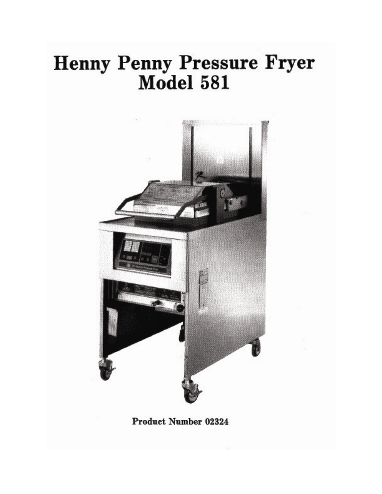
1-1. PRESSURE FRYER The Henny Penny Pressure Fryer is a basic unit of food pro-
cessing equipment which is used only in institutional and
commercial food service operations.
P-H-T A combination of Pressure, Heat, and Time is automatically
controlled to produce the optimum in a tasty, appealing
product.
Pressure Pressure is basic to this method of food preparation. The pres-
sure is developed from the natural moisture of the food. The
patented lid traps this moisture and uses it as steam. Because
the steam builds rapidly, a greater part of the natural juices
are retained within the food. An operation valve vents excess
steam from the pot and maintains constant live steam pressure.
Heat Heat generated is another important factor of the pressure fryer.
Energy savings is realized due to the unit’s short frying time,
low temperature, and heat retention of the stainless steel
cookpot.
Time Time is important because the shorter time involved in frying
foods results in additional economies for the user. Foods are
table ready in less time than it would take to fry them in a conventional open-type fryer.
1-2. PROPER CARE As in any unit of food service equipment, the Henny Penny
Pressure fryer does require care and maintenance. Requirements for the maintenance and cleaning are contained in this
manual and must become a regular part of the operation of the
unit at all times.
1-3. ASSISTANCE Should you require outside assistance, call your local
distributor in your area, or call 1-800-417-8405 or
937-456-8405.
201 1-1
Page 8
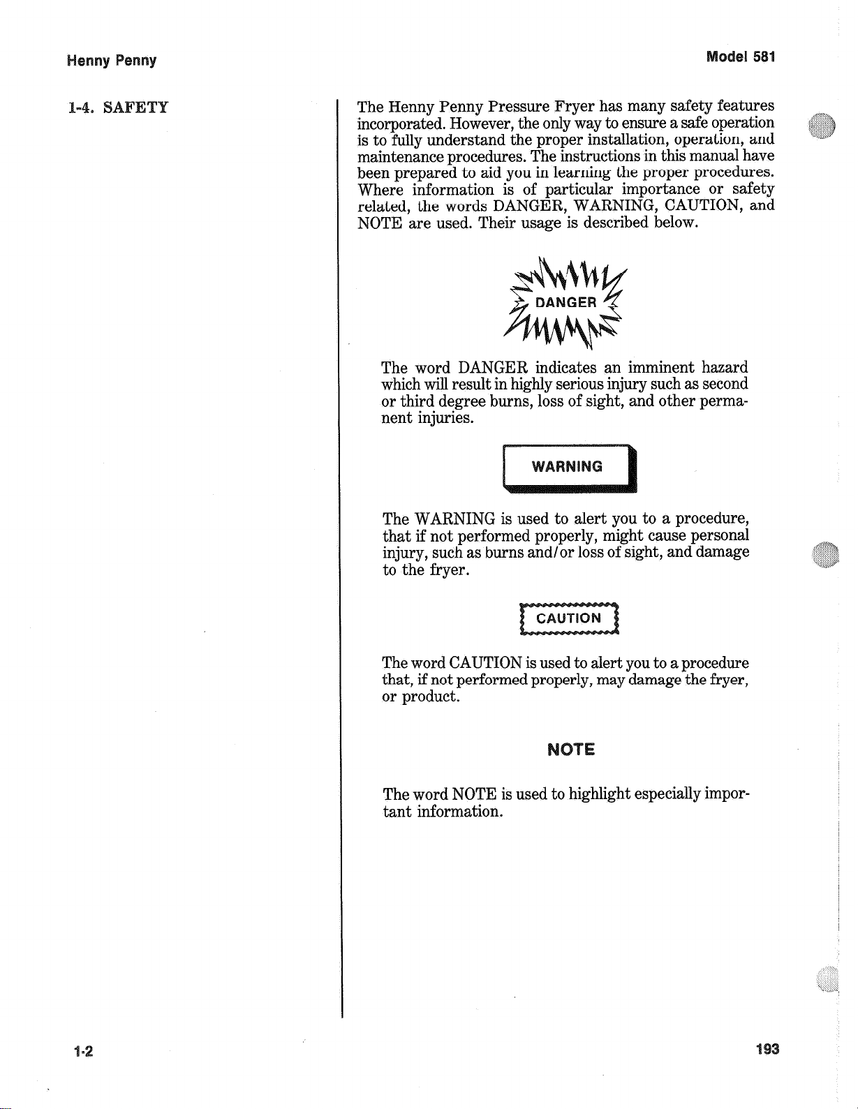
The Henny Penny Pressure Fryer has many safety features
incorporated. However, the only way to ensure a safe operation
is to fully understand the proper installation, operation, and
maintenance procedures. The instructions in this manual have
been prepared to aid you in learning the proper procedures.
Where information is of particular importance or safety
related, the words DANGER, WARNING, CAUTION, and
NOTE are used. Their usage is described below.
The word DANGER indicates an imminent hazard
which will result in highly serious injury such as second
or third degree burns, loss of sight, and other permanent injuries.
The WARNING is used to alert you to a procedure,
that if not performed properly, might cause personal
injury, such as burns and/or loss of sight, and damage
to the fryer.
The word CAUTION is used to alert you to a procedure
that, if not performed properly, may damage the fryer,
or product.
The word NOTE is used to highlight especially important information.
Page 9
1. Cut and remove the metal bands from the carton.
2. Remove the carton lid and lift the main carton off the
fryer.
3. Remove corner packing supports (4).
4. Cut and remove the metal bands holding the fryer to the
pallet.
Do not unlatch the lid before completion of steps 5, 6,
and 7.
5. Remove the fryer from the pallet. See page 2-2.
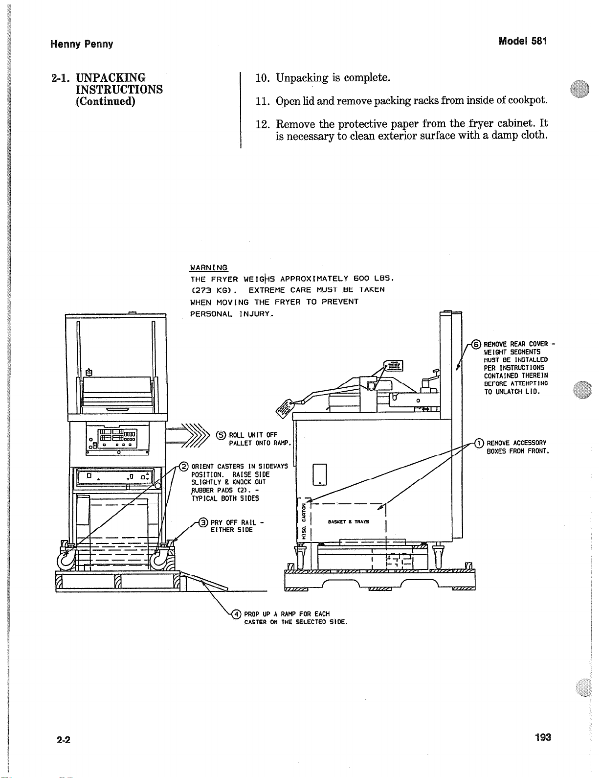
The fryer weighs approximately 600 lbs. (273 KG).
Extreme care should be taken when moving the fryer
to prevent personal injury.
6. Load the Counterweight Assembly. See page 2-3.
7. Replace rear cover.
8. Cut warning tags from the lid assembly. The lid may now
be unlatched.
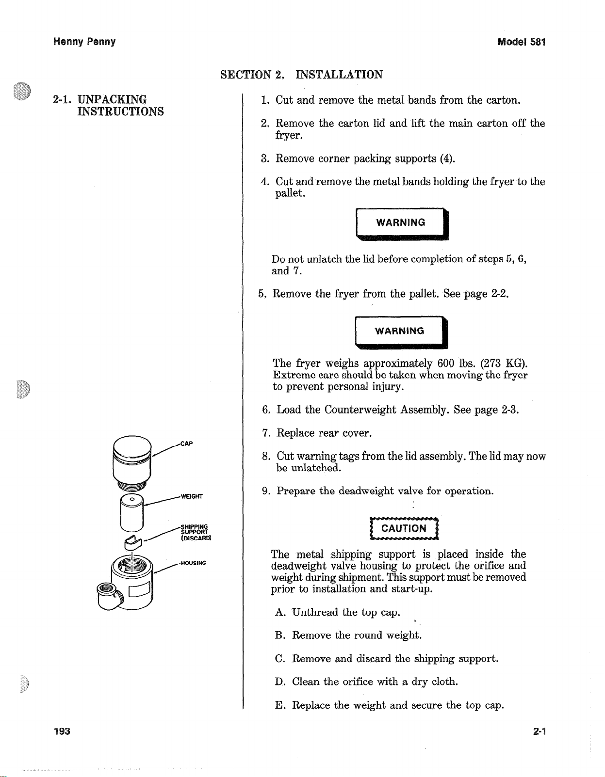
9. Prepare the deadweight valve for operation.
The metal shipping support is placed inside the
deadweight valve housing to protect the orifice and
weight during shipment. This support must be removed
prior to installation and start-up.
A. Unthread the top cap.
B. Remove the round weight.
C. Remove and discard the shipping support.
D. Clean the orifice with a dry cloth.
m
E. Replace the weight and secure the top cap.
Page 10
10. Unpacking is complete.
a:‘,‘:!:,!>j)
4S$~@b
11. Open lid and remove packing racks from inside of cookpot.
12. Remove the protective paper from the fryer cabinet. It
is necessary to clean exterior surface with a damp cloth.
WARN I NG
THE FRYER WEI+S APPROXlMATELY 600 L6S.
(273 KG).
WHEN MOVING THE FRYER TO PREVENT
PERSONAL INJURY.
EXTREME CARE MUST BE TAKEN
-@REMOVE REAR COVER UEIGHT SEGMENTS
MUST BE INSTALLED
PER INSTRUCTIONS
CONTAINED THEREIN
BEFORE ATTEMPTING
TO UNLATCH LID.
A%
;,,, ::&
‘{
”
@ ROLL UNIT OFF
PALLET ONTO RAMP
ORIENT CASTERS IN SlOEWAYS
POSITION.
SLIGHTLY 8 KNOCK OUT
JIUBSER PADS (2). -
TYPICAL BOTH SIDES
RAISE SIDE
EITHER SIOE
PROP UP 4 RAMP FOR EACH
CASTER ON THE SELECTEO SIDE.
1 REMOVE ACCESSORY
f-0
BOXES FRON FRONT.
Page 11
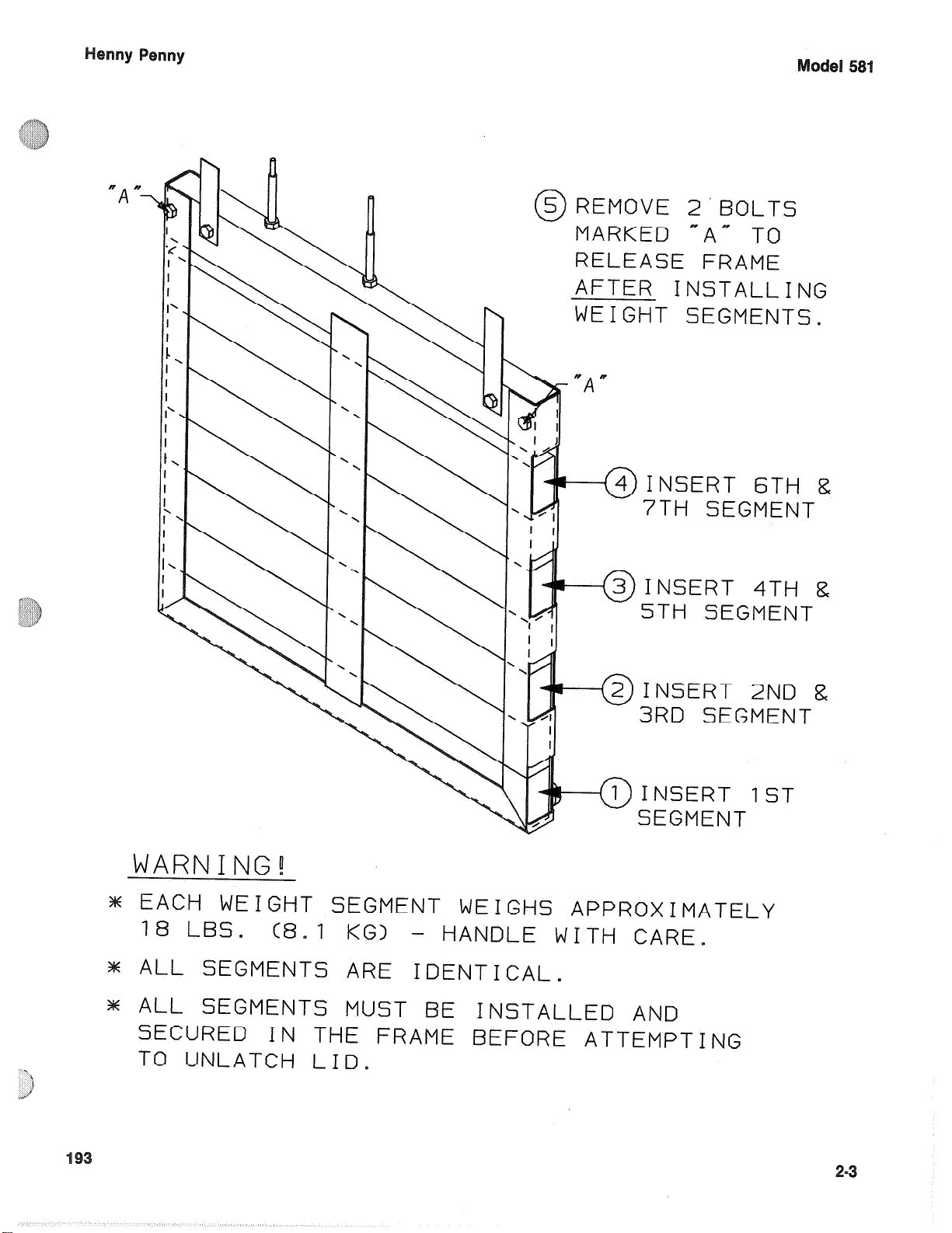
5 REMOVE 2’BOLTS
0
MARKED “A” TO
RELEASE FRAME
AFTER INSTALLING
WEIGHT S
EGMENTS.
INSERT 6TH &
7TH SEGMENT
I
C3J INSERT 4Tti 8
\
\
Y
Y \ .
\
5TH SEGMENT
2 INSERT 2ND &
0
3RD SEGMENT
' 9
.,I
--(~)INsE
SEGMENT
WARNING!
m EACH
18 LBS.
m ALL SEGMENTS ARE
m ALL SEGMENTS MUST BE INSTALLED AND
SECURED
TO UNLATCH
WEIGHT SEGMENT WEIGHS
(8.1 KG> - HANDLE WITH CARE.
IDENTICAL.
IN
THE FRAME BEFORE ATTEMPTING
LID.
APPROXIMATELY
RT IST
Page 12
58
The proper location of the fryer is very important for operation, speed, and convenience. Choose a location which will
provide easy loading and unloading without interfering with
the final assembly of food orders. Operators have found that
frying from raw to finish, and holding the product in a warmer
provides fast continuous service. Landing or dumping tables
should be provided next to at least one side of the fryer. Keep
in mind the best efficiency will be obtained by a straight line
operation, i.e. raw in one side and finished out the other side.
Order assembly can be moved away with only a slight loss of
efficiency.
For proper operation, the fryer must be level from side to side
and front to back. Using a level placed on the flat areas around
the frypot collar, adjust the casters until the unit is level.
The fryer should be located with provision for venting into adequate exhaust hood or ventilation system. This is essential to
permit efficient removal of the steam exhaust and frying odors.
Special precaution must be taken in designing an exhaust
canopy to avoid interference with the operation of the fryer.
Make certain the exhaust hood is designed high enough to allow
for proper opening of the fryer lid. We recommend you con-
sult a local ventilation or heating company to help in designing an adequate system.
The electric fryer is available from the factory wired for
2081120 or 240/120 volts, three phase 60 Hz. service. The power
cord may be already attached to the fryer, or provided at
installation. Check the data plate on the right side of the fryer
to determine the correct power supply.
This fryer must be adequately and safely grounded.
Refer to local electrical codes for correct grounding
procedures. If fryer is not adequately grounded,
electrical shock could result.
A separate disconnect switch with proper capacity fuses or
breakers must be installed at a convenient location between
the fryer and the power source. It should be an insulated copper
conductor rated for 600 volts and 90 “6. For runs longer than
50 feet, use the next, larger size wire.
Page 13
Each Henny Penny pressure fryer was completely checked and
tested prior to shipment. However, it is good practice to check
the unit again after installation.
1. Cook a round of product.
2. Check to see that the indicator needle in the pressure
gauge is reading in the “Operating Zone”.
Should the pressure gauge read beyond the “Operating
Zone” turn the Power/Pump switch to the “OFF” position and refer to the Operation Control Valve Section.
Continued use of the unit at this high pressure could
result in serious injuries and severe burns.
3. Make sure lid gasket is not leaking, and no steam is coming
from safety relief valve.
4. Cheek the drain valve and fill line check valve
5. At the end of the cook cycle:
* The control will sound off by beeping.
The fryer will automatically depressurize.
6. Push the timer button.
7. When all the pressure has exhausted (observe pressure
gauge) open the lid.
DO NOT ATTEMPT TO OPEN LID UNTIL THE
PRESSURE DROPS TO ZERO. Opening the lid when
the cookpot is pressurized will allow hot shortening and
moisture to escape from the cookpot, resulting in severe
burns.
8. Let rack hang for 3-5 seconds, then proceed to take out
racks of chicken and place onto a bun pan.
Page 14
If all the above functions have been performed satisfactorily
the fryer is ready for operation.
All operators, as well as maintenance and management
personnel, must throughly read and understand the
Operation Section prior to putting the fryer into operation. Failure to adhere to these instructions could result
in serious bodily injury or property damage.
2-8. INTERNATIONAL
ELECTRICAL
~~REMENT~
Units being used outside the United States may not be shipped
with the power cord attached to the unit because of the
different wiring codes. The fryers are available from the
factory wired for 208240,380 and 415 volts, 3 phase, 50 Hertz
service. A terminal block is mounted inside the fryer for the
cable wiring. A decal on the inside of the right side panel will
help in the wiring of the unit.
To install the power cord, follow these procedures:
1. Remove the side panel from the right side of the unit.
2. Remove the front panel, behind the filter knob and quick
disconnect.
3. Thread the cable through the strain relief on the junction
box.
4. Attach the wires to the terminal block according to the
wiring diagram on the side panel.
5. Pull the slack out of the cable and tighten the screws on
the strain relief.
6. Pull the slack out of the cable and secure it with.the clamp
on the back of the cookpot.
Be sure the cable doesn’t sag, or it could interfere with
the use of the portable filter.
Page 15
7. Pull the slack out of the cable and secure it with the clamp
on the frame, at the rear, right leg of fryer.
Be sure enough slack is out of the cable so it doesn’t
extend out past the portable filter stop bracket at the
bottom of the fryer frame. The cable could interfere
with the portable filter, not allowing it to be pushed
all the way in. This could cause hot shortening to spill
onto the floor.
8. Wiring the fryer is now complete.
Page 16

Henny Penny Model 581
BOIL-OVER PREVENTION
IN HENNY PENNY FRYERS
FAILURE TO FOLLOW THESE INSTRUCTIONS CAN RESULT IN SHORTENING
OVERFLOWING THE FRYPOT, WHICH COULD CAUSE SERIOUS BURNS,
PERSONAL INJURY, FIRE AND/OR PROPERTY DAMAGE.
• THE SHORTENING MAY BE STIRRED ONLY DURING THE MORNING
START UP PROCEDURE. DO NOT STIR THE SHORTENING AT ANY
OTHER TIME
• FILTER THE SHORTENING AT LEAST TWICE A DAY
• FILTER ONLY AFTER POWER SWITCH IS OFF
• BRUSH ALL CRACKLINGS FROM FRYPOT SURFACES AND THE COLD
ZONE DURING THE FILTERING PROCESS
• MAKE SURE THE FRYER IS LEVEL
• BE CERTAIN THE SHORTENING IS NEVER ABOVE THE UPPER FRYPOT
“FILL” LINE
• USE RECOMMENDED PRODUCT LOAD SIZE, 22lbs. (9.9 kg)
FOR ADDITIONAL INFORMATION ON THESE INSTRUCTIONS REFER TO THE
HENNY PENNY SERVICE.
FOR ASSISTANCE CALL THE HENNY PENNY SERVICE DEPARTMENT AT
1-800-417-8405, or1-937-456-8405.
2-8 203
Page 17
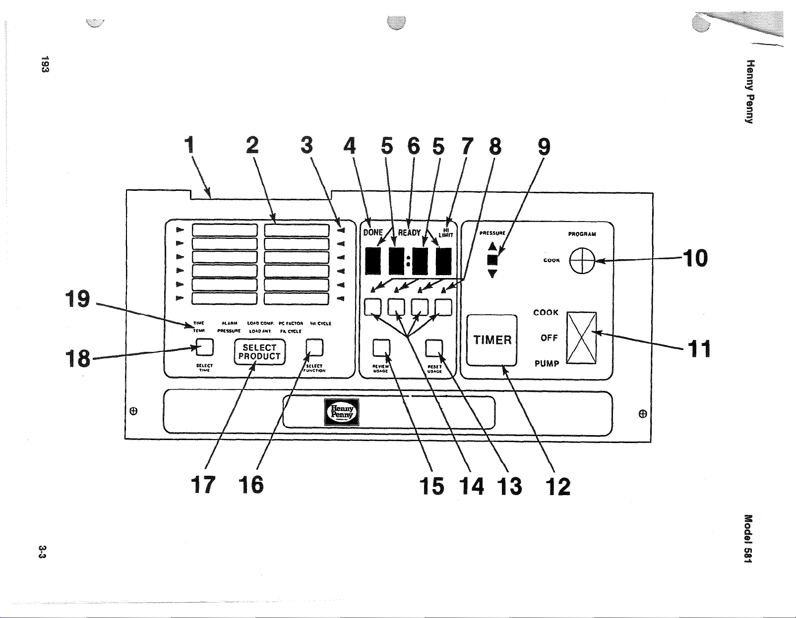
This section describes the fuctions of all operating controls and
their components.
1
Control Decal
Menu Board
Menu Indicator
Done Indicator
Digital Display
Ready Light
High Limit Light
The control decal is a self-adhesive decal which displays the
desired functions.
The menu board displays the products that have been programmed within the control.
The menu indicators, when illuminated, point to the product
cycle the control is in.
This indicator shows the operator the cooking cycle is
completed.
The digital display is a LED type display which shows the
temperature of the shortening and the timer countdown of the
frying cycle.
The ready light indicates the shortening has reached operating
temperature and the operator may drop product.
This light will illuminate in the event the manual reset high
limit has tripped. This indicates the shortening temperature
has exceeded the safe operating limit.
Change Switch
Indicators
Pressure Light
Key Switch
Power Switch
Timer Switch
These indicators, when illuminated, show which part of the
display is functional for programming such as increasing or
decreasing temperature, time, etc.
When illuminated, shows the solenoid is closed which allows
pressure to build.
When in the COOK position the unit is in the normal operation
mode. In the PROGRAM position the unit is in the program
mode.
This switch is a sealed illuminated rocker type switch. When
in the COOK position, applies power to the control. When in
the PUMP position applies power to the pump motor.
The timer switch is used to start, stop, or abort a cooking cycle.
Page 18
Itx?
I
escriptio
I
~u~~tiQ~
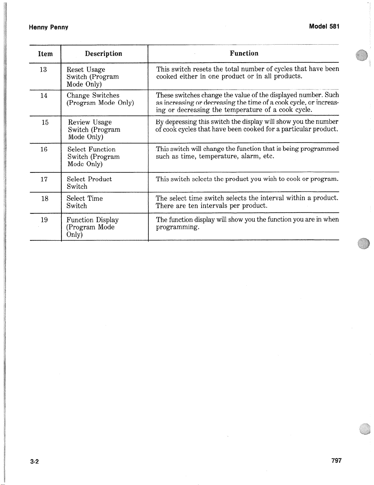
13 Reset Usage
Switch (Program
Mode Only)
14
15
16 Select Function
17
18
19 Function Display
Change Switches
(Program Mode Only)
Review Usage
Switch (Program
Mode Only)
Switch (Program
Mode Only)
Select Product
Switch
I
Select Time
Switch
(Program Mode
Only)
This switch resets the total number of cycles that have been
cooked either in one product or in all products.
These switches change the value of the displayed number. Such
as increasing or decreasing the time of a cook cycle, or increasing or decreasing the temperature of a cook cycle.
By depressing this switch the display will show you the number
of cook cycles that have been cooked for a particular product.
This switch will change the function that is being programmed
such as time, temperature, alarm, etc.
This switch selects the product you wish to cook or program.
I
The select time switch selects the interval within a product.
There are ten intervals per product.
The function display will show you the function you are in when
programming.
Page 19
COOK
PROGRlU
Page 20
Henny Penny Model 581
3-1. OPERATING CONTROLS (Continued)
1. Cook/Pump Switch This is a three-way switch with center “OFF” position. Move
the switch to the position marked “POWER” to operate the
fryer. Move the switch to the position marked “PUMP” to
operate the filter pump. Certain conditions must be met prior
to operation of the filter pump. These conditions are covered
later in this section.
2. Cookpot This reservoir holds the cooking shortening, and is designed to
accommodate the Heat Exchanger, 8 head of product and an
adequate cold zone for collection of cracklings.
3. Cooking Rack This stainless steel rack consists of five baskets that contain
the food product during and after frying.
4. Lid Gasket The lid gasket provides the pressure seal for the cookpot
chamber.
5. Operating Valve The dead weight style operating pressure relief valve is used to
maintain a constant level of steam pressure within the cookpot.
Any excess steam pressure is vented through the exhaust stack.
NOTE
Remove the dead weight cap, and clean the cap, weight, and
orifice, once a day to prevent over pressurization of the
cookpot
6. Safety Relief Valve The safety relief valve is an ASME approved spring loaded
valve set at 14.5 psi (999 mbar). In the event the operation
valve becomes obstructed, this safety valve will release excess
pressure, keeping the cookpot chamber at 14.5 psi (999 mbar).
If this occurs, turn the Power/Pump switch to the “OFF”
position to release all pressure from the cookpot.
7. Safety Relief Valve Ring THE RING IS NOT TO BE PULLED.
Severe burns from the steam will result.
8. Gauge The pressure gauge indicates the pressure inside the cookpot.
3-4 201
Page 21
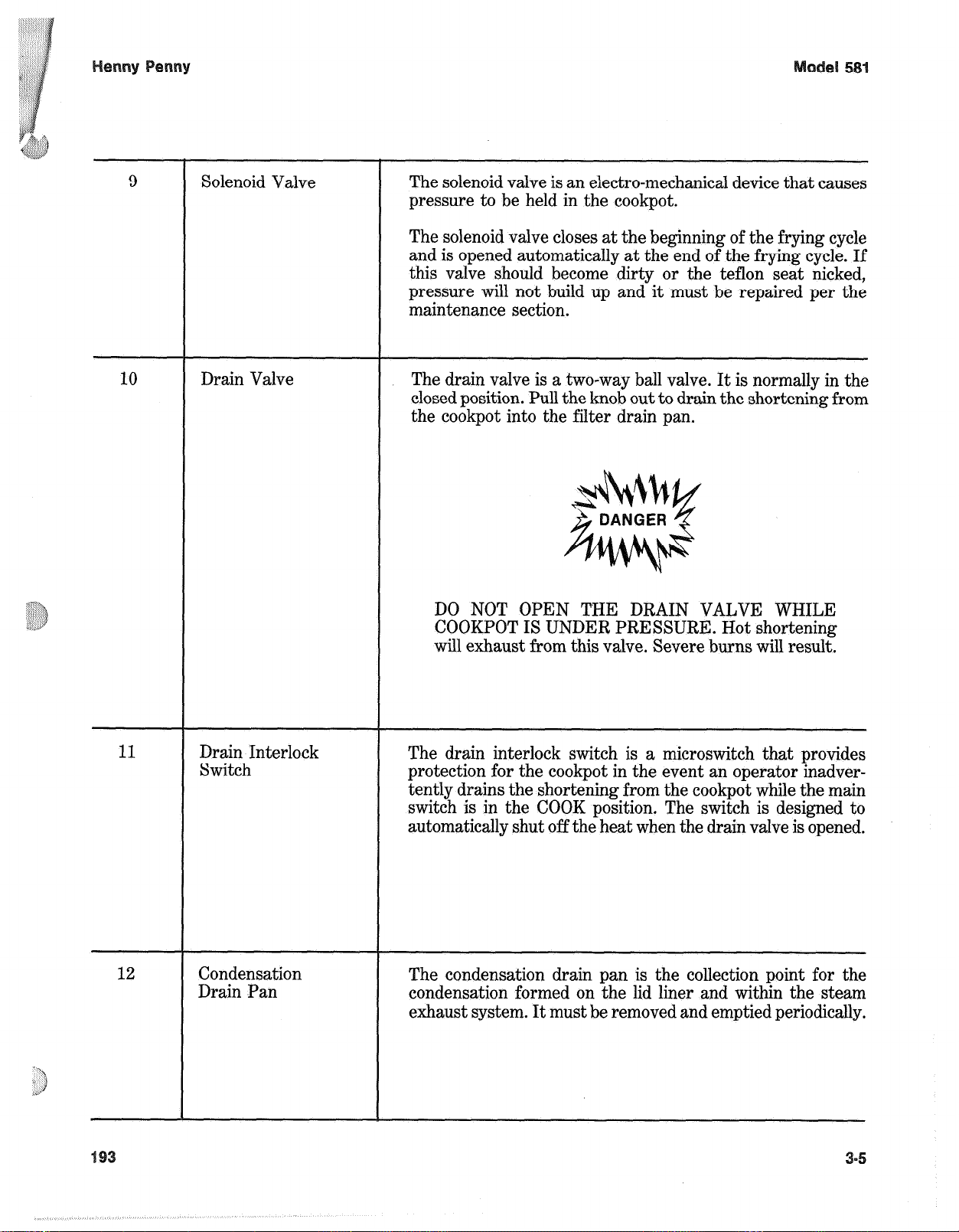
9
Solenoid Valve
The solenoid valve is an electro-mechanical device that causes
pressure to be held in the cookpot.
The solenoid valve closes at the beginning of the frying cycle
and is opened automatically at the end of the frying cycle. If
this valve should become dirty or the teflon seat nicked,
pressure will not build up and it must be repaired per the
maintenance section.
10
11
Drain Valve
Drain Interlock
Switch
The drain valve is a two-way ball valve. It is normally in the
closed position. Pull the knob out to drain the shortening from
the cookpot into the filter drain pan.
DO NOT OPEN THE DRAIN VALVE WHILE
COOKPOT IS UNDER PRESSURE. Hot shortening
will exhaust from this valve. Severe burns will result.
The drain interlock switch is a microswitch that provides
protection for the cookpot in the event an operator inadvertently drains the shortening from the cookpot while the main
switch is in the COOK position. The switch is designed to
automatically shut off the heat when the drain valve is opened.
Condensation
Drain Pan
The condensation drain pan is the collection point for the
condensation formed on the lid liner and within the steam
exhaust system. It must be removed and emptied periodically.
Page 22
Henny Penny Model 581
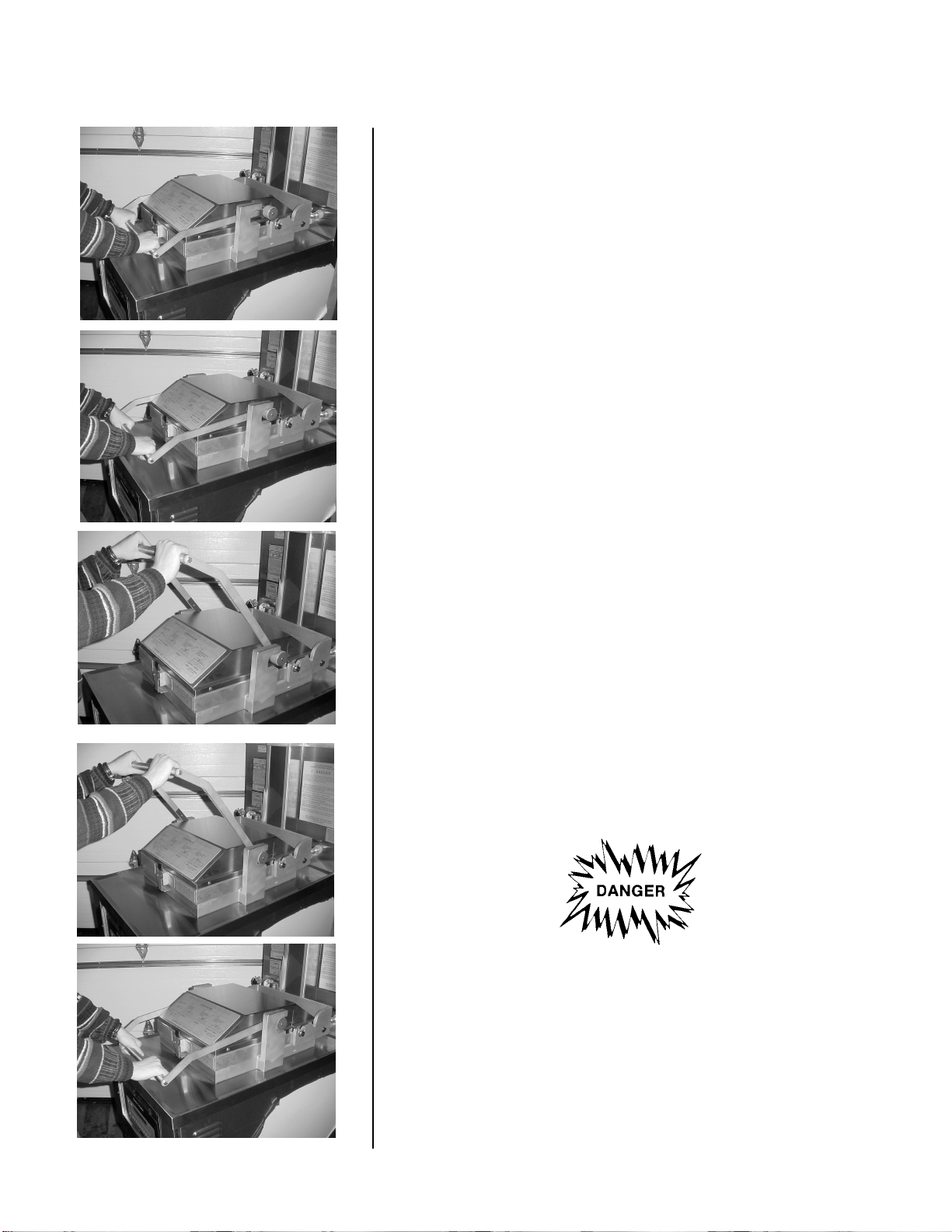
3-2. LID OPERATION
To close lid:
1. Lower the lid until lid latches into place.
1
2. Pull lid handle forward until it stops.
2 3. Lift up on the lid handle until it stops.
4. Bring lid handle out towards you until it stops.
3
5. Push lid handle down, locking lid in place.
4
DO NOT ATTEMPT TO OPEN LID UNTIL THE
PRESSURE DROPS TO ZERO. Lid is locked when fryer
is under pressure. Do not attempt to force the lid latch or
open the lid while under pressure. Opening the lid when
the cookpot is pressurized will allow hot shortening and
moisture to escape from the cookpot, resulting in severe
burns.
5
3-6 201
Page 23
Henny Penny Model 581
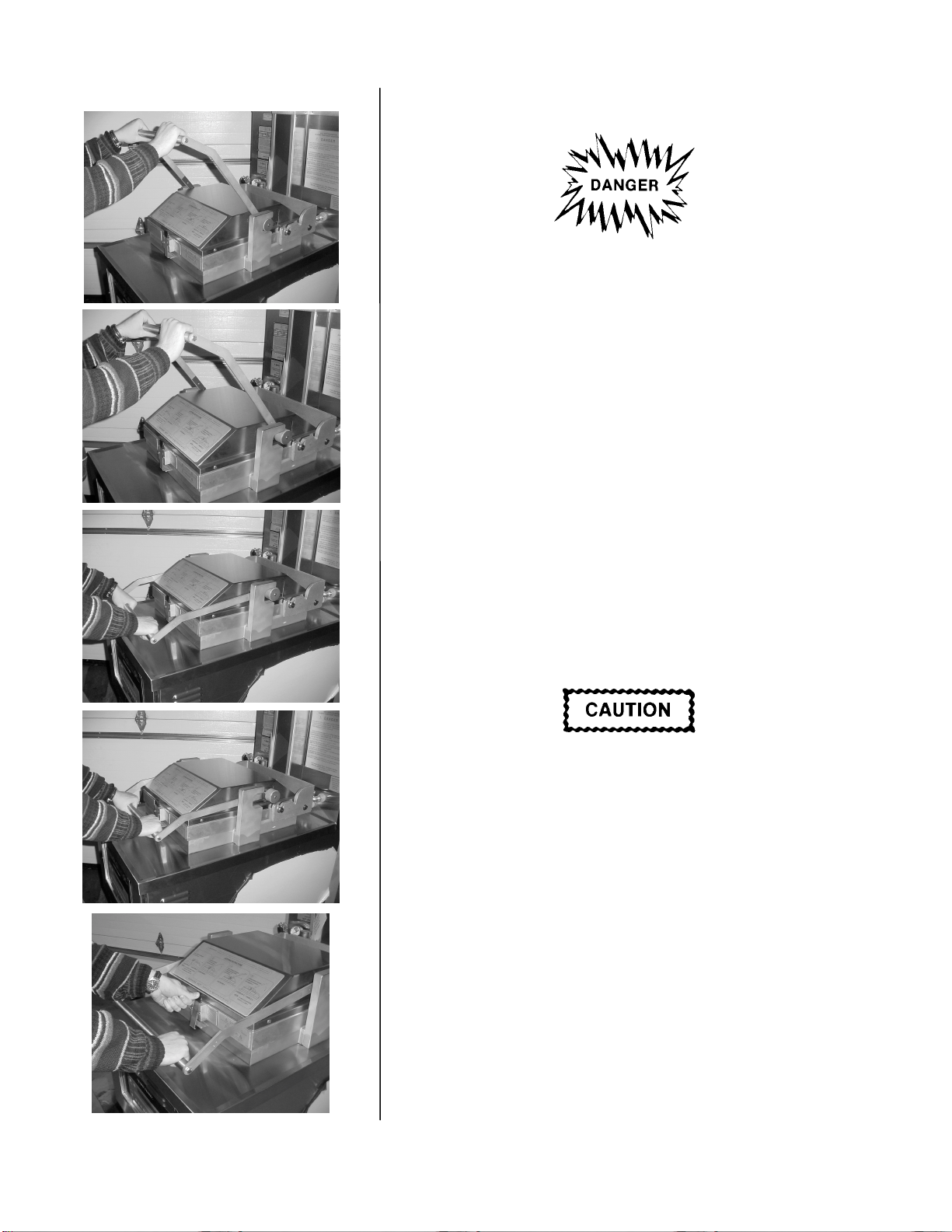
3-2. LID OPERATION (Continued) To open lid:
DO NOT ATTEMPT TO OPEN LID UNTIL THE
1 PRESSURE DROPS TO ZERO. Lid is locked when fryer
is under pressure. Do not attempt to force the lid latch or
open the lid while under pressure. Opening the lid when
the cookpot is pressurized will allow hot shortening and
moisture to escape from the cookpot, resulting in severe
burns.
1. Gently raise handle until it stops.
2
2. Push handle back until it stops.
3. Lower handle.
3
DO NOT raise the lid with the handle in the up position.
Lower the handle before attempting to raise the lid, or
damage to the lid could result.
4
4. Push handle back.
5. Unlatch the front lid latch and raise lid with handle.
5
201 3-7
Page 24
Henny Penny Model 581
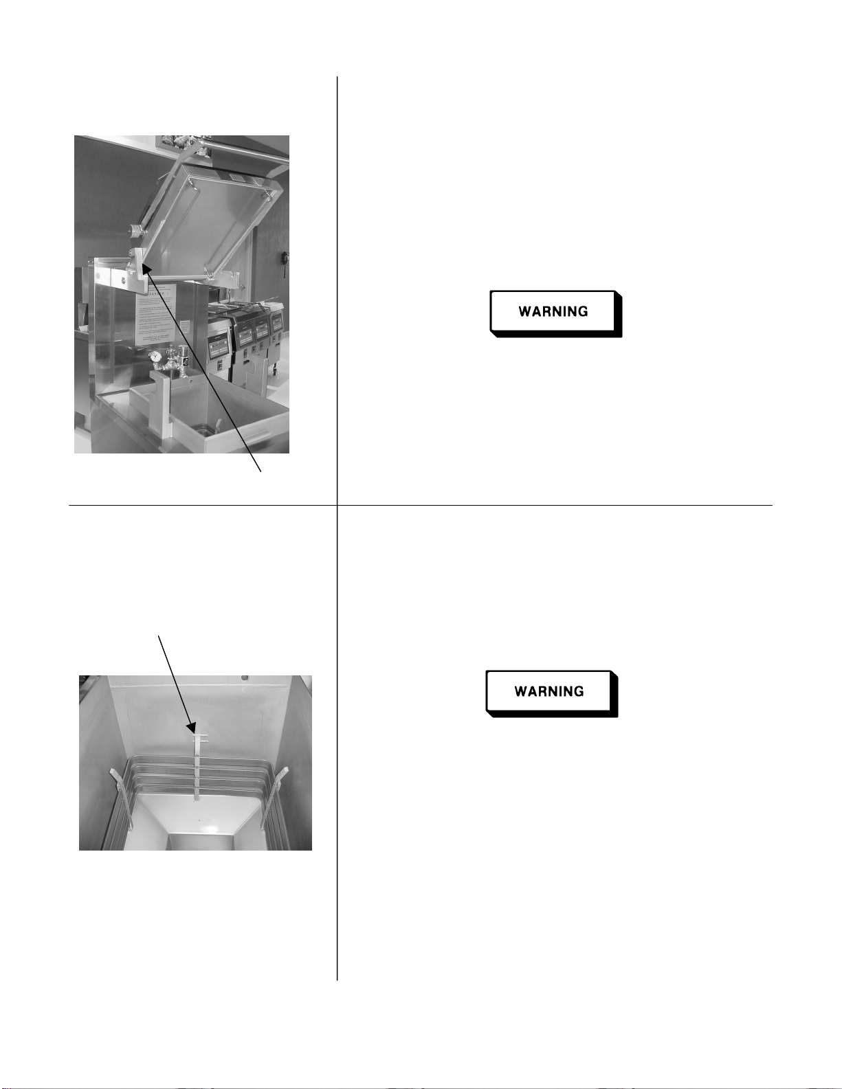
3-2. LID OPERATION Tilt the lid back for ease of filtering or servicing.
(Continued)
1. With the lid completely raised, remove the Cooking Rack
from lid.
2. Using the handle, tilt lid back until the metal “kickstand”
fits in the groove in the lid support. (See photo).
Make sure the “kickstand” is secure in the groove of the lid
support, or severe injuries could result.
Kickstand
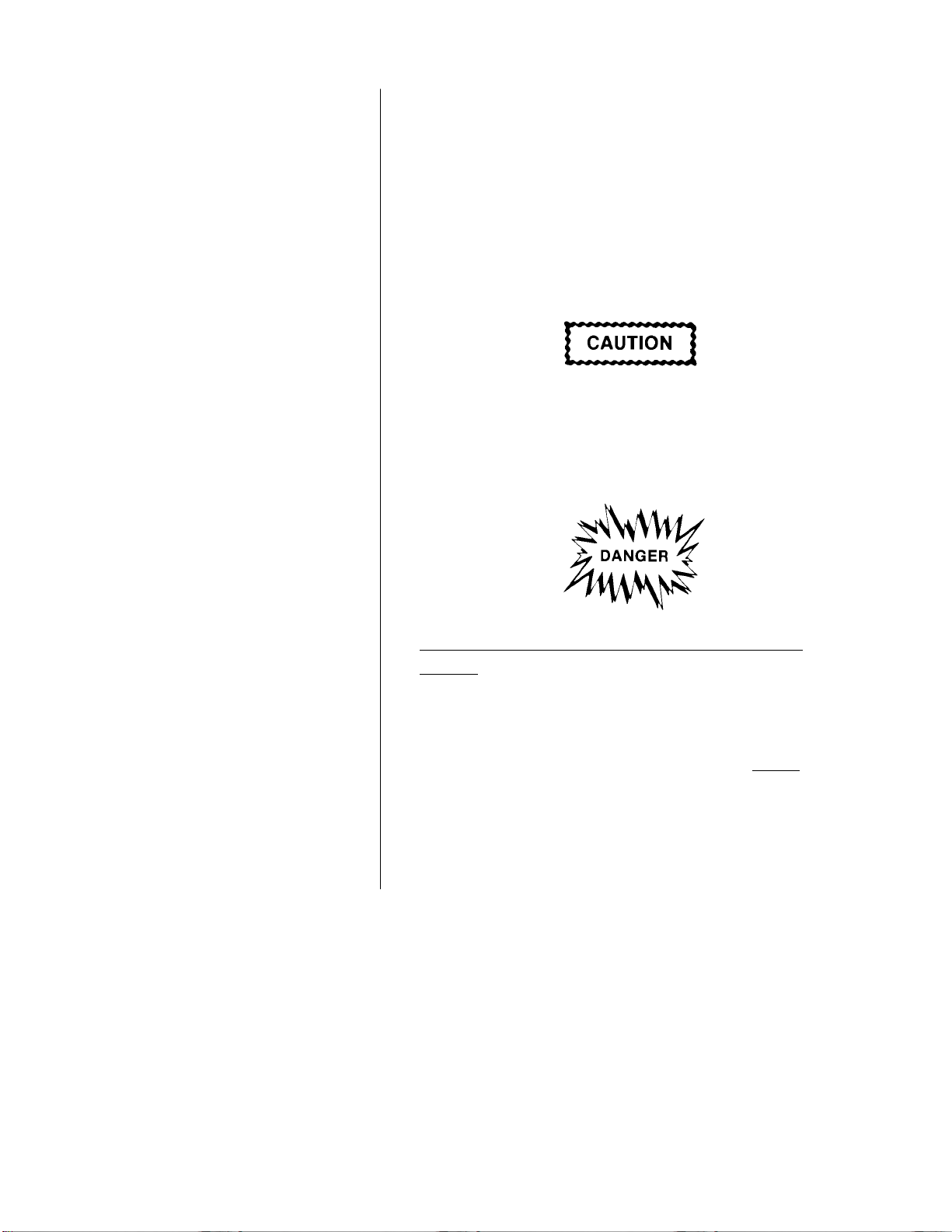
3-3. FILLING OR ADDING 1. It is recommended that a high quality frying shortening be
SHORTENING used in the pressure fryer. Some low-grade shortenings
have high moisture content and will cause foaming and
boiling over.
2. If a solid shortening is used, it can be melted into a liquid
level Indicator lines
first, then poured into the cookpot. Attempting to melt solid
shortening in the cookpot may cause burning or scorching
of the fresh shortening.
GLOVES SHOULD BE WORN AND CARE MUST
BE TAKEN WHEN POURING HOT SHORTENING.
Severe burns could result. Also, when adding fresh
shortening to existing shortening, care must be taken to
avoid splashing or severe burns could result.
3. The electric model requires 100 lbs. The pot has two level
indicator lines inscribed on the rear wall of the frypot
which show when the heated shortening is at the proper
level. Maintain hot shortening at the upper level indicator
line. Add fresh shortening as needed.
4. Cold shortening should be filled to 1/2 inch below lower
level indicator line.
3-8 203
Page 25
Henny Penny Model 581
3-4. CARE OF THE
SHORTENING 1. To protect the shortening when the fryer is not in imme-
diate use, the fryer should be put into the Idle Mode.
2. Frying breaded products requires filtering to keep the
shortening clean. The shortening should be filtered at least
twice a day; after lunch rush and at the end of the day.
3. Maintain hot shortening at the upper level indicator line.
Add fresh shortening as needed.
The shortening level must always be above the heating
elements when the fryer is heating, and up to the upper
level indicator line on the frypot. Failure to follow these
instructions could result in a fire and/or damage to the
fryer.
With prolonged use, the flashpoint of shortening is
reduced. Discard shortening if it shows signs of excessive
smoking or foaming. Serious burns, personal injury, fire,
and/or property damage could result.
To avoid shortening overflowing the frypot, do not
overload the basket with product, or place product with
extreme moisture content into basket. The recommended
product load size is 22 lbs (9.9 kg.) Serious burns, personal
injury, fire and/or property damage could result.
203 3-9
Page 26
The following procedures should be followed on the initial startup of the fryer each time the fryer is brought from a cold, or
shut down, condition back into operation.
1. Check to see that all of the control switches are turned off.
2. Be sure the drain valve is CLOSED.
3. Remove carrier and baskets from lid and tilt lid back (see
section 3-2).
4. Fill the cookpot to a level at
l/2
inch below the bottom fill
line (see section 3-3).
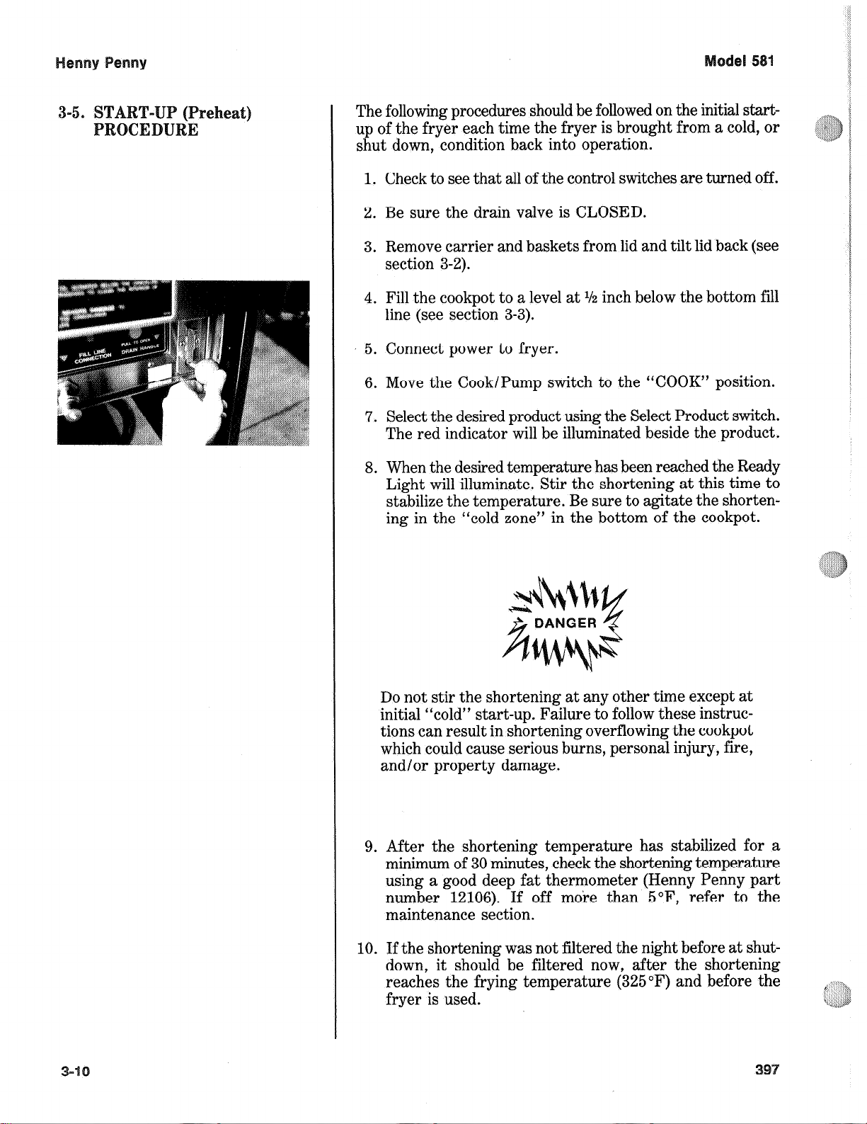
5. Connect power to fryer.
6. Move the Cook/Pump switch to the “COOK” position.
7. Select the desired product using the Select Product switch.
The red indicator will be illuminated beside the product.
8. When the desired temperature has been reached the Ready
Light will illuminate. Stir the shortening at this time to
stabilize the temperature. Be sure to agitate the shortening in the “cold zone”
in the bottom of the cookpot.
Do not stir the shortening at any other time except at
initial “cold” start-up. Failure to follow these instructions can result in shortening overflowing the cookpot
which could cause serious burns, personal injury, fire,
and/or property damage.
9. After the shortening temperature has stabilized for a
minimum of 30 minutes, check the shortening temperature
using a good deep fat thermometer (Henny Penny part
number 12106). If off more than 5”F, refer to the
maintenance section.
10. If the shortening was not filtered the night before at shutdown, it should be filtered now, after the shortening
reaches the frying temperature (325°F) and before the
fryer is used.
Page 27
If the shortening temperature exceeds 420°F immediately shut off the power at the main circuit breaker
and have the fryer repaired. If shortening
(temperature) exceeds its flashpoint, fire will occur,
resulting in severe burns and/or property damage.
11. Raise the lid up and place carrier and baskets onto lid.
12. Lower lid and emerse baskets into shortening, then raise
lid. This will keep the product from sticking to the baskets.
You are now ready to start frying.
Do not permit the fryer to set for an extended period
of time at high temperature (325 “F or above), because
the shortening will break down much sooner. When the
fryer is not being used for frying, put the controls to
the “IDLE” position.
1. Take the chicken parts, 2,4,6, or 8 cut-up chickens, from
the cooler and place in a scullery sink. Wash the chicken
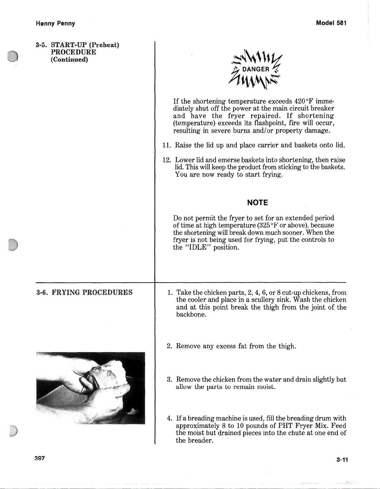
and at this point break the thigh from the joint of the
backbone.
2. Remove any excess fat from the thigh.
I
3. Remove the chicken from the water and drain slightly but
allow the parts to remain moist.
4. If a breading machine is used, fill the breading drum with
approximately 8 to 10 pounds of PHT Fryer Mix. Feed
the moist but drained pieces into the chute at one end of
the breader.
Page 28
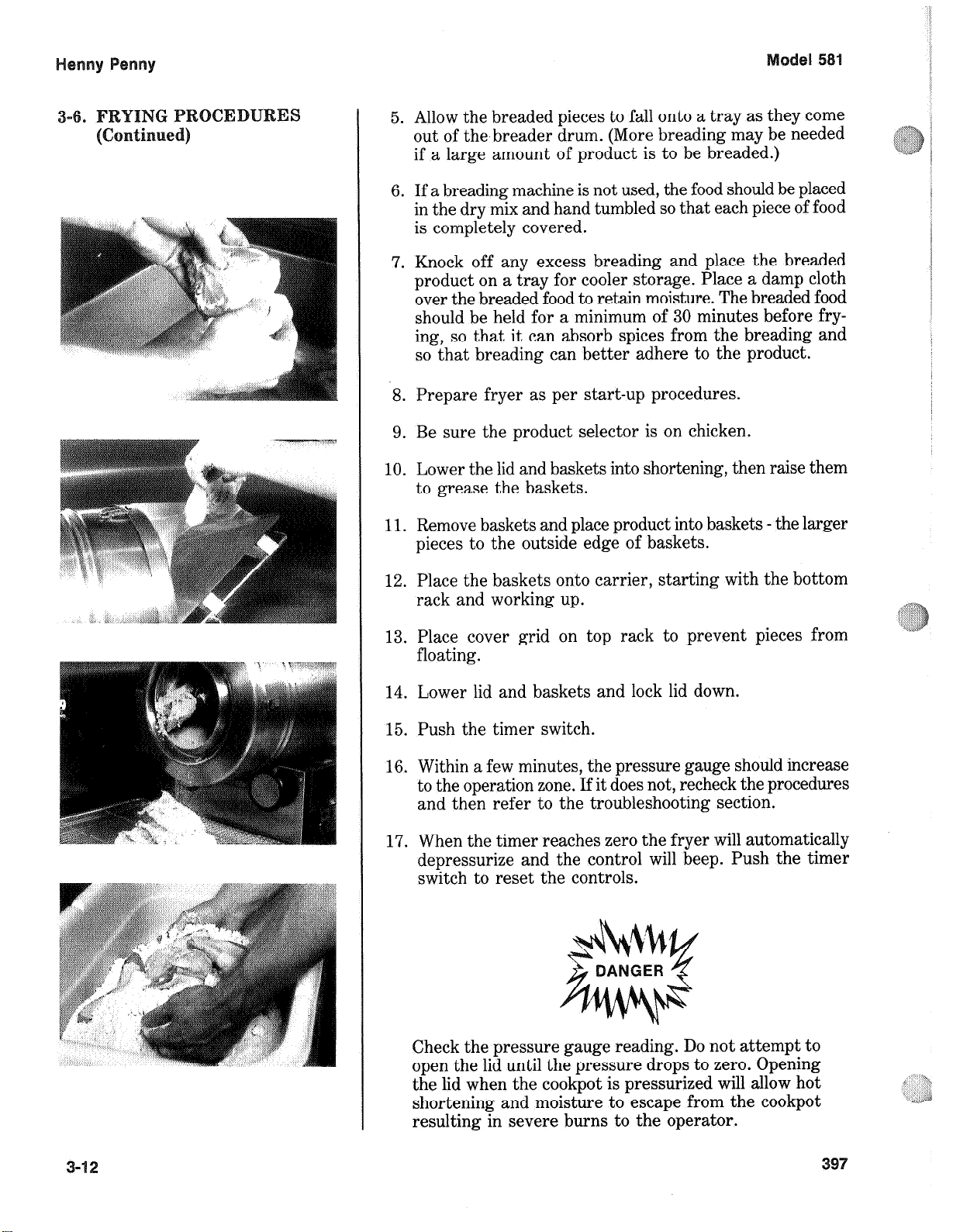
5. Allow the breaded pieces to fall onto a tray as they come
out of the breader drum. (More breading may be needed
if a large amount of product is to be breaded.)
6. If a breading machine is not used, the food should be placed
in the dry mix and hand tumbled so that each piece of food
is completely covered.
7. Knock off any excess breading and place the breaded
product on a tray for cooler storage. Place a damp cloth
over the breaded food to retain moisture. The breaded food
should be held for a minimum of 30 minutes before frying, so that it can absorb spices from the breading and
so that breading can better adhere to the product.
8. Prepare fryer as per start-up procedures.
9. Be sure the product selector is on chicken.
10. Lower the lid and baskets into shortening, then raise them
to grease the baskets.
11. Remove baskets and place product into baskets - the larger
pieces to the outside edge of baskets.
12. Place the baskets onto carrier, starting with the bottom
rack and working up.
13. Place cover grid on top rack to prevent pieces from
floating.
14. Lower lid and baskets and lock lid down.
15. Push the timer switch.
16. Within a few minutes, the pressure gauge should increase
to the operation zone. If it does not, recheck the procedures
and then refer to the troubleshooting section.
17. When the timer reaches zero the fryer will automatically
depressurize and the control will beep. Push the timer
switch to reset the controls.
Check the pressure gauge reading. Do not attempt to
open the lid until the pressure drops to zero. Opening
the lid when the cookpot is pressurized will allow hot
shortening and moisture to escape from the eookpot
resulting in severe burns to the operator.
Page 29
18. After the pressure drops to zero, open the lid.
19. Let baskets hang for approximately 15 seconds before
removing the baskets.
20. Place the product into a warming cabinet immediately.
21. Before frying the next load, allow time for the shortening to reheat. (Wait until the ready light comes on.)
Frying breaded food requires frequent filtering. Taste the cold
shortening every day for flavor. Watch the shortening for
foaming during frying cycles. Discard the shortening as soon
as it shows signs of foaming. Clean the frypot as follows each
time the shortening is changed or filtered.
1. Turn the power switch to the “OFF” position.
The best results are obtained when the shortening is
filtered at the normal frying temperature.
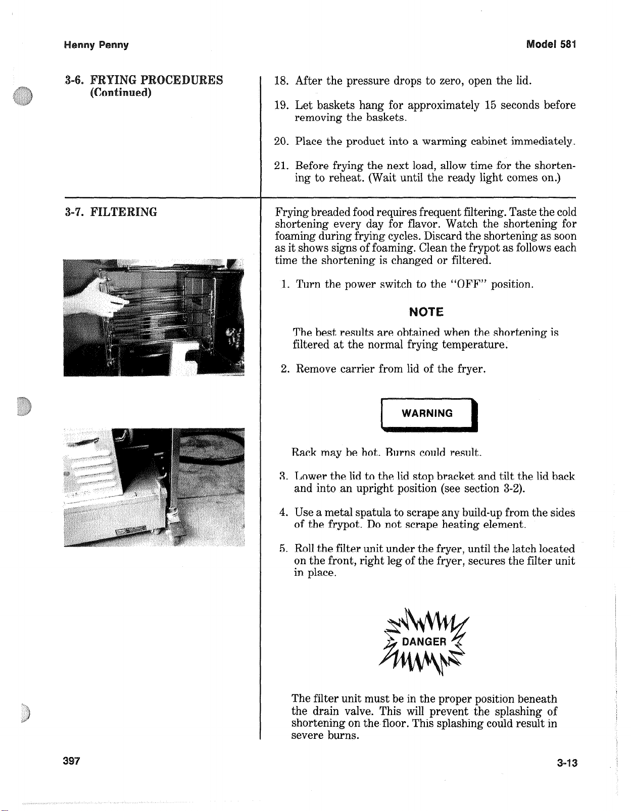
2. Remove carrier from lid of the fryer.
I
Rack may be hot. Burns could result.
3. Lower the lid to the lid stop bracket and tilt the lid back
and into an upright position (see section 3-2).
4. Use a metal spatula to scrape any build-up from the sides
of the frypot. Do not scrape heating element.
5. Roll the filter unit under the fryer, until the latch located
on the front, right leg of the fryer, secures the filter unit
in place.
The filter unit must be in the proper position beneath
the drain valve. This will prevent the splashing of
shortening on the floor. This splashing could result in
severe burns.
NING
Page 30
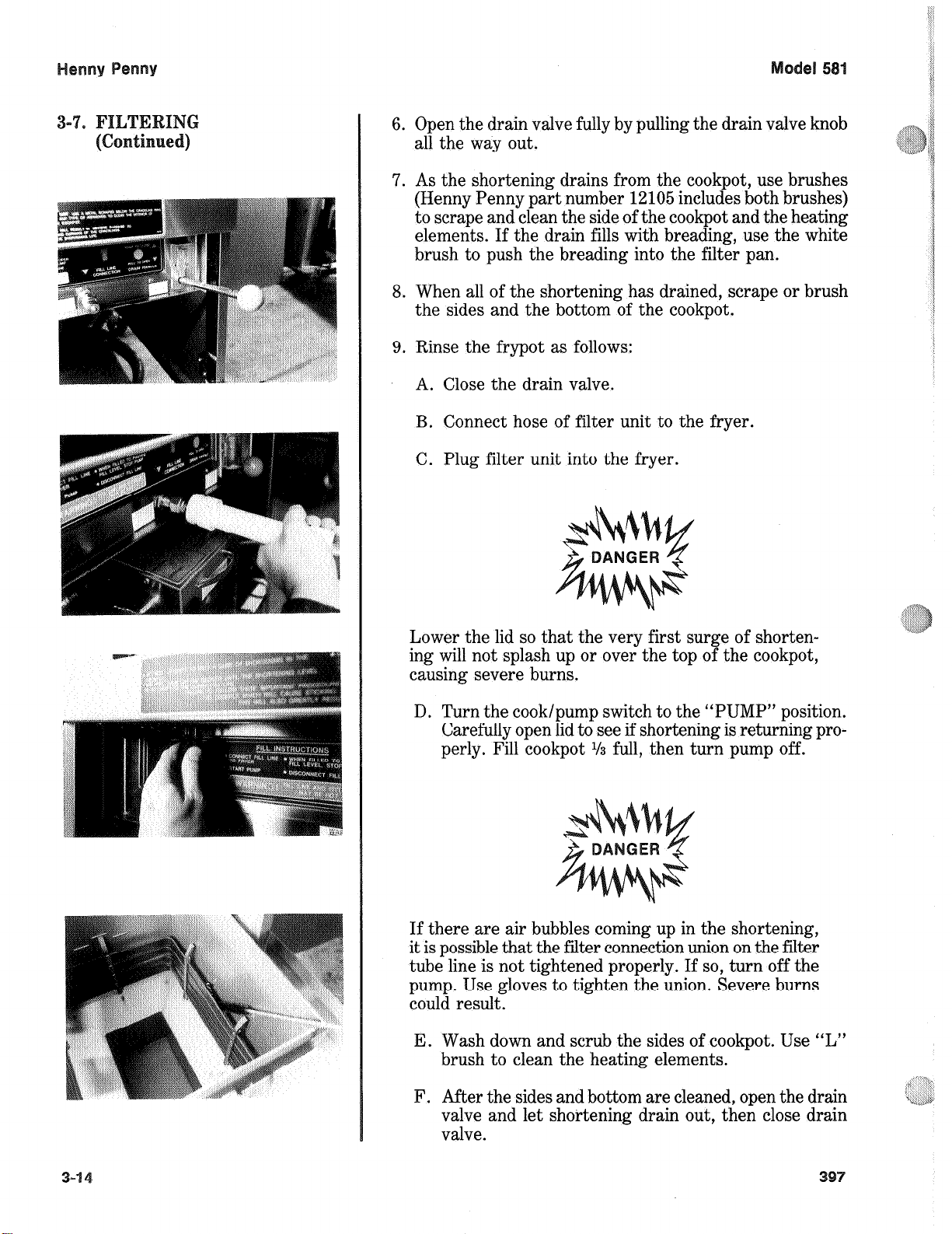
6. Open the drain valve fully by pulling the drain valve knob
all the way out.
7. As the shortening drains from the cookpot, use brushes
(Henny Penny part number 12105 includes both brushes)
to scrape and clean the side of the cookpot and the heating
elements. If the drain fills with breading, use the white
brush to push the breading into the filter pan.
8. When all of the shortening has drained, scrape or brush
the sides and the bottom of the cookpot.
9. Rinse the frypot as follows:
A. Close the drain valve.
B. Connect hose of filter unit to the fryer.
C. Plug filter unit into the fryer.
Lower the lid so that the very first surge of shorten- Lower the lid so that the very first surge of shortening will not splash up or over the top of the cookpot,
causing severe burns.
D. Turn the cook/pump switch to the “PUMP” position.
Carefully open lid to see if shortening is returning pro-
perly. Fill cookpot
l/3
full, then turn pump off.
If there are air bubbles coming up in the shortening,
it is possible that the filter connection union on the filter
tube line is not tightened properly. If so, turn off the
pump. Use gloves to tighten the union. Severe burns
could result.
E. Wash down and scrub the sides of cookpot. Use “L”
brush to clean the heating elements.
F. After the sides and bottom are cleaned, open the drain
valve and let shortening drain out, then close drain
valve.
Page 31

10. Lower the lid down to the lid stop bracket during the first
surge of pumping and pump all the shortening out of the
filter pan and back into the frypot.
11. When the pump is pumping air only, the shortening in the
cookpot will appear to be boiling. Move the main power
switch to the “OFF” position.
When the appearance of boiling occurs, immediately
turn the pump off. This will prevent aeration of the
shortening, therefore increasing shortening life.
12. Check the level of the shortening in the eookpot. Add fresh
shortening if necessary, until it reaches the point between
the level indicators.
13. After completing the filtering operation, empty and
replace the condensation drain pan.
14. If frying is to be continued at this time, move the main
power switch back to the “COOK” position, and allow time
for reheating of the shortening.
The filter envelope should be changed after lo-12 filterings
or whenever it becomes clogged with crumbs. Proceed as
follows:
1. Unplug portable filter (PF-180) from cooker and roll filter
unit out from under the cooker.
2. Remove back cover from filter unit and remove crumb
basket. Discard crumbs and clean thoroughly with soap
and water. Rinse thoroughly with hot water.
3. Unscrew dairy union from standpipe and remove filter
head assembly from filter pan.
This union will be hot. Use protective glove or cloth,
or severe burns will result.
397
3-15
Page 32

4. Lift the screen assembly from the drain pan.
5. Wipe the shortening and crumbs from the drain pan. Clean
the drain pan with soap and water. Thoroughly rinse with
hot water.
6. Unthread the suction standpipe from the screen assembly.
7. Remove filter clips and discard the filter envelope.
8. Clean the top and bottom filter screen with soap and
water. Rinse thoroughly with hot water.
Be sure that the filter screens, crumb catcher, filter
clips, and the suction standpipe are thoroughly dry
before assembly of filter envelope, as water will dissolve
the filter paper.
9. Assemble the top filter screen to the bottom filter screen.
10. Slide the screens into a clean filter envelope.
11. Fold the corners in, then double fold the open end.
12. Clamp the envelope in place with the two filter retaining
clips.
13. Place large washer on top of filter paper and screw on the
suction standpipe assembly.
14. Place complete filter screen assembly back into filter drain
pan.
15. Place filter assembly over suction standpipe assembly, and
connect filter union by hand. Do not use a wrench to
tighten.
16. Place crumb basket into position in the back of the filter
pan and place cover over it.
17. Portable filter is now ready to be slid under the cooker
for filtering.
Page 33

The following steps will help prevent filter pump problems:
1. Make certain the filter paper envelope is properly installed
over the filter screens. Make sure the open end of the
envelope is properly folded over and clamped in place with
the retaining clips, so that the envelope is sealed and
crumbs cannot enter.
2. Make sure the filter valve is kept closed at all times during
frying.
3. Make sure all the shortening has been pumped from the
filter lines and the pump by allowing the filter pump motor
to run until the shortening in the cookpot appears to be
bubbling or boiling.
The filter motor is equipped with a manual reset button in the
event the motor’s thermal protector actuates. This reset button
is located on the front of the filter head assembly, behind a
hinged circular door. Wait approximately 5 minutes before
attempting to reset this protector device.
Use steady, hard pressure on the reset button until a
definite “click” is heard. The button takes some force
to reset.
To prevent burns caused by splashing shortening, the
unit’s power cord must be unplugged before resetting
the filter pump motor’s manual reset protection device.
Page 34

After the initial installation of the fryer, as well as before every
change of shortening, the cookpot should be thoroughly cleaned
as follows:
1. Turn the main power switch OFF.
The filter drain pan must be in position under the drain
valve to prevent splashing or spilling of hot liquids.
Failure to do so will result in splashing and severe
burns.
2. If hot shortening is present in the cookpot, it must be
drained by slowly pulling the drain valve knob.
3. Close the drain valve. Discard the shortening in the filter
pan. Roll the empty filter pan under the fryer.
4. Lower the lid to the lid stop bracket and tilt lid back, so
that the lid won’t interfere with cleaning.
5. Fill the cookpot to the level indicators with hot water. Add
8 to 10 ounces of fryer cleaner (Henny Penny part number
12101) to the water and mix thoroughly.
Always wear safety goggles or face shield and protective rubber gloves when cleaning the cookpot, as the
cleaning solution is highly alkaline. Avoid splashing or
other contact of the solution with eyes or skin. Severe
burns or blindness could result. Carefully read the
instructions on the cleaner. If solution comes in contact with eyes, rinse thoroughly with cool water and
see a physician immediately.
6. Enter Boil Out mode. (See page 6-8.)
NEVER PRESSURIZE FRYER TO CLEAN. Leave
lid open. Water under pressure is super heated and will
cause severe burns if it comes in contact with skin.
Page 35

Henny Penny Model 581
3-11. CLEANING THE FRYPOT
(Continued)
DO NOT let the cleaning solution boil. If the cleaning
solution in the cookpot starts to foam and boil over, DO
NOT TRY TO CONTAIN IT BY CLOSING THE
FRYER LID or severe burns could result.
7. Using the fryer brush (Henny Penny part number 12105)
scrub the inside of the cookpot, the lid liner, and around
the counter-top of the fryer.
Do not use steel wool, other abrasive cleaners or cleaners/sanitizers containing chlorine, bromine, iodine or
ammonia chemicals, as these will deteriorate the
stainless steel material and shorten the life of the unit.
Do not spray the unit with water, such as, with a garden
hose. Failure to follow this caution could cause component
failure.
8. After cleaning, turn off the main power switch. Open
the drain valve and drain the cleaning solution from the
cookpot into the drain pan and discard.
9. Close the drain valve and refill the cookpot with hot
water to proper level.
10. Add approximately 16 ounces of distilled vinegar and
heat the solution to no more than 195ºF (91ºC).
11. Using a clean brush, scrub the interior of the cookpot and
lid liner. This will neutralize the alkaline left by the
cleaning compound.
12. Drain the vinegar rinse water and discard.
13. Rinse down the cookpot, using clean hot water.
14. Thoroughly dry the drain pan, and the cookpot interior.
NOTE
Make sure the inside of the cookpot, the drain valve
opening, and all parts that come in contact with the
new shortening are as dry as possible.
15. Refill the fryer with fresh shortening
203 3-19
Page 36

1. Drain and clean the frypot.
Turn the main circuit breaker off and unplug the electrical
2.
cord if possible.
3. Close the lid.
4. Remove and clean condensation drain pan.
At the end of each day, the operating valve must be cleaned
as follows:
1. Turn the COOK/PUMP switch to OFF. Be sure all
pressure has been released and open the lid.
2. Unscrew the valve cap and remove the cap and weight.
Use gloves. Valve cap may be very hot and burns could
result.
3. Clean the cap and weight in hot detergent water. Make
certain to thoroughly clean the inside of the valve cap and
the weight.
4. Clean the exhaust tube with stainless steel brush (Henny
Penny part number 12147).
Clean orifices and the inside of the valve body with a clean
5.
lint free cloth.
6. Dry the weight and valve cap.
7. Replace weight and valve cap. Hand tighten the cap.
Page 37

el 5
At the end of each day or shift, perform the following
procedures:
1. Move the COOK/PUMP switch to the OFF position.
2. Filter the shortening.
3. Place racks and carrier in sink for cleaning.
4. Clean operating valve per previous paragraph.
3-21
Page 38

Page 39

This section provides troubleshooting information in the form
of an easy to read table.
If a problem occurs during the first operation of a new fryer,
recheck the installation per the Installation Section of this
manual.
Before troubleshooting, always recheck the operation procedures per Section 3 of this manual.
To isolate a malfunction, proceed as follows:
1. Clearly define the problem (or symptom) and when it
occurs.
2. Locate the problem in the Troubleshooting table.
3. Review all possible causes. Then, one-at-a-time work
through the list of corrections until the problem is solved.
4. Refer to the maintenance procedures in the Maintenance
Section to safely and properly make the checkout and
repair needed.
If maintenance procedures are not followed correctly,
injuries and/or property damage could result.
Page 40

Product Color Not
Correct:
A. Too Dark
Temperature too high.
Check temperature setting
in the program mode. See
section on programming.
Remove and replace defective probe.
B. Too Light
Shortening too old.
Shortening too dark.
Breading product too far
in advance.
Wrong cook button
pushed.
Temperature too low.
Fryer incorrect preheat.
Slow fryer heat-up/
recovery.
Wrong cook button
pushed.
Change shortening.
Filter shortening.
Change shortening.
Bread product closer to
actual frying period.
Be sure to select the
correct product to be
cooked.
e Check temperature setting.
a Remove and replace defec-
tive probe.
Allow proper preheat time.
Refer to heating elements
in the maintenance section.
Be sure to select the
correct product to be
cooked.
C. Product
Greasy
Shortening old.
Temperature too low.
Wrong cook button
pushed.
Cookpot overloaded.
Product not removed from
cookpot immediately after
depressurization.
Replace shortening.
Check temperature setting.
Temperature not recovered
when product was dropped
in cookpot.
Remove and replace defective probe.
Be sure to select the
correct product to be
cooked.
Reduce cooking load.
Remove product
immediately after
depressurization of the
eookpot.
Page 41

B. Too Light
Temperature too low.
Check temperature setting.
Remove and replace defec-
tive probe.
C. Product
Greasy
Fryer incorrect preheat.
Slow fryer heat-up/
recovery.
Wrong cook button
pushed.
0 Shortening old.
Temperature too low.
0 Cookpot overloaded.
Product not removed from
cookpot immediately after
end of cycle.
0 Allow proper preheat time.
* Refer to heating elements
in the maintenance section.
@ Be sure to select the
correct amount of product
to be cooked.
e Replace shortening.
@ Check temperature setting.
e Temperature not recovered
when product was dropped
in cookpot.
e Remove and replace defec-
tive probe.
0 Reduce cooking load.
0 Remove product
immediately after end of
cycle.
D. Spotted
Product
Improper separation of the
product.
Breading not uniform on
the product.
Burned breading particles
on product.
Product sticking together.
Load product into basket
properly.
Sift breading regularly.
Separate product during
breading.
Filter the shortening more
frequently.
Separate product prior to
pressure cooking.
Page 42

E. Dryness of
Product
Moisture loss prior to
cooking.
Product Flavor
(Taste):
A. Salty Taste
Overcooking the product.
Low operating pressure.
Wrong cook button pushed.
Breading mixture is too
salty.
Incorrect choice of
breading.
Reduce cooking time.
Reduce cooking
temperature.
Cheek pressure gauge
reading, check for pressure
leaks.
Be sure to select the
correct product to be
cooked.
Sift breading after each
use.
Incorrect breading mixture.
Discard old breading.
Use breading designed for
the desired product.
urned Taste
6. Bland Taste
Burned shortening flavor.
Cookpot not properly
cleaned.
aw product not fresh.
Breading mixture incorrect
for product (spice content
too low).
Cooking temperature too
high (spice flavors lost).
Replace shortening.
Drain and clean cookpot.
Use fresh raw products.
Use breading designed for
desired product.
Check temperature.
Page 43

D. Rancid Taste
Shortening too old.
Replace shortening, and
follow recommended care
and use of shortening.
General:
A. Meat
Separation
From Bone
B. Bone Color
Not Proper
Non compatible products
cooked within the same
shortening.
Infrequent filtering.
Raw product not fresh.
Incorrect meat cut.
Overcooking.
Product not fresh.
Using frozen product (black
bone).
Improper processing of
product (black bone).
Replace shortening.
Use compatible products,
and follow recommended
care and use of shortening.
Replace shortening, and
follow recommended care
and use of shortening.
Use fresh product.
Use correct meat cutting
procedures.
Check cooking time.
Use fresh product.
Use fresh product.
Use proper processing
procedure for product.
6. Breading Falh
Off
D. Product
Sticking
Together
Product not thoroughly
cooked (red bone).
Incorrect breading
procedures.
Product partially frozen.
Product breaded too long
prior to cooking.
Improper loading
procedure.
Wrong cook button pushed.
Check cooking time.
Check cooking temperature.
Use correct breading
procedure.
Thoroughly thaw the
product, before breading.
Refer to breading and
frying instructions.
Properly load product per
loading procedures.
Be sure to select the
correct product to be
cooked.
Page 44

With switch in
POWER position,
the fryer is completely inoperative
(NO POWER)
Open circuit.
Check to see that unit is
plugged in.
Check the breaker or fuse
at supply box.
Check control panel fuses
(electric model only).
Check voltage at wall
receptacle.
Check MAIN POWER
switch. Replace if defective.
Check cord and plug.
Pressure will not
exhaust at end of
cooking cycle.
Operating
pressure too high
Exhaust line from solenoid
valve to condensation tank
clogged.
Solenoid valve clogged.
Dead weight clogged.
Turn unit off and allow
fryer to cool to release
pressure from cookpot;
clean all pressure lines,
exhaust stacks, and condensation tank.
Check and clean solenoid
valve per Maintenance
Section on Solenoid Valve.
Turn unit off and allow
fryer to cool to release
pressure from cookpot;
remove dead weight and
clean.
Page 45

Henny Penny Model 581
Problem Cause Correction
LID/PRESSURE SECTION (Continued)
• Exhaust line to stack clogged • Clean exhaust line to stack.
DO NOT OPERATE UNIT
IF HIGH PRESSURE
CONDITIONS EXIST,
SEVERE INJURIES AND
BURNS WILL RESULT.
Place the Power/Pump
switch in the “OFF”
position immediately. Release
the pressure by allowing unit
to cool. The pressure will
then drop. Do not resume use
of unit until cause of high
pressure has been found
and corrected.
Pressure does not • Not enough product in fryer • Place proper quantity of
build or product not fresh. fresh product within
cookpot to generate steam.
• Metal shipping spacer not • Remove shipping spacer.
removed from dead weight. See Unpacking Section.
• Lid open or not latched. • Close and latch lid.
• Solenoid valve leaking or • Check or clean solenoid
not closing. valve per maintenance
section on the solenoid
valve.
• Dead weight valve leaking. • Repair per maintenance sec tion on operating valve.
• Pressure not programmed. • Check programming.
• Lid gasket leaking. • Reverse gasket or lid needs
adjusted. See Sections 5-10
& 5-13.
1201 4-7
Page 46

Henny Penny Model 581
Problem Cause Correction
LID/PRESSURE SECTION (Continued)
• Safety relief valve leaking. • Check and replace if
necessary per maintenance
section on the relief valve.
• Pressure pad broken or crushed. • Replace pressure pads.
Lid won’t move • Cable on Counterweight • Put cable on Counterweight
up or down loose or broken per section on
Counterweight Cable.
• Check operation of • Make proper adjustments.
counterweight carriage in
rear of cooker.
HEATING OF SHORTENING SECTION
Shortening will • Blown fuse or tripped • Reset breaker or replace
not heat circuit breaker at supply fuse.
box or control panel.
• Blown fuse at control panel. • Check fuse per Main tenance Section on fuses
• Faulty Cook/Pump switch. • Check Cook/Pump switch
per Maintenance Section on
Cook/Pump switch.
• Faulty Cord and Plug. • Check cord and plug and
power at wall receptacle.
• Faulty contactor. • Check contactor per
Maintenance Section on
contactors.
• Faulty Drain Switch. • Check drain switch per
Maintenance Section on
Drain Switches.
• Faulty PC board. • Remove and replace control
panel.
• Faulty high limit control • Check high limit control
switch. switch per Maintenance
Section on High Limits.
4-8 1201
Page 47

Heating of
shortening too
slow (Electric
Model)
Low or improper voltage.
Weak or burnt out
element(s).
Use a meter and check the
receptacle against data
plate.
Check heating element(s)
per Maintenance Section on
Heating Elements.
Shortening
overheating
(Electric Model)
Points in contactor bad.
Wire(s) loose.
Burnt or charred wire
connection.
Check shortening
temperature.
Check contactor for not
opening.
Faulty PC Board.
Faulty probe.
Check contactor per
Maintenance Section on
Contactors.
Tighten.
Replace wire and clean
connectors.
Check temperature setting
in the program mode.
Check faulty contactor per
Maintenance Section on
Contactors.
Remove and replace control
panel.
Remove and replace probe.
Foaming or boil-
ing o,ver of
shortening
Water in shortening.
Condensation line stopped
up.
Improper or bad
shortening.
Improper filtering.
At end of cooking cycle,
drain shortening and clean
cookpot. Add fresh
shortening.
Remove and clean condensation line.
Use recommended
shortening.
Refer to the procedure
covering filtering the
shortening.
Page 48

Cold zone full of cracklings.
Filter shortening.
Shortening will
not drain from
cookpot
Shortening leaking
through drain
valve.
Improper rinsing after
cleaning the fryer.
Too much stirring.
Drain valve clogged with
crumbs.
Drain valve will not open by
pulling the knob.
Obstruction in drain.
Faulty drain valve.
Clean and neutralize the
cookpot. Rinse with vinegar
to remove the alkaline, then
rinse with hot water and
dry cookpot.
Only stir on initial heat-up.
Open valve - push cleaning
brush through drain open-
ing from inside of cookpot.
Replace cotter pins in valve
coupling.
Remove obstruction.
Replace drain valve.
Page 49

The following guide requires voltage to be present when troubleshooting the control. When
the guide refers to connecting pins on the power connection, unplug the power connector
from the board and refer to the attached illustration. These are numbered 1 through 9.
Using a strand of #16 gauge wire, connect the pins as numbered in the troubleshooting
guide. Extreme caution must be taken when connecting these pins to avoid control board
damage or electrical shock.
With switch in COOK position, the fryer is
completely inoperative (no power switch light).
With switch in COOK position, the fryer is
completely inoperative (power switch light on,
pump works).
Control operative - all lights on - primary
contactor engages - no heat or pressure.
Control operative -
pressure - primary contactor does NOT
engage.
Control operative - all lights on - has pressure
- no heat.
all lights on - no heat or
Check to see if unit has voltage.
Check fuses.
Defective power switch.
+S Check voltage on pins 1 and ‘7 on the power
connector, 10 VAC.
If voltage is present, check fuse on control
board.
@ If fuse is defective, replace fuse.
Check 5 amp fuse located on heat shroud fuse OK.
Check voltage from center of fuse to ground
- 208/240 VAC.
Defective transformer.
Connect pins 4 and 6 on the power
connector.
If contactor engages - replace control boarcJ
If contactor does not engage, replace
contactor.
Control operative - all lights on - heat on - no
pressure - pressure light OFF.
Control operative pressure - pressure light ON.
all lights on - heat on - no
Connect pins 3 and 6 on the power
connector.
If solenoid engages - defective control
board.
If solenoid does not engage - defective
solenoid coil - 2081240 VAC.
Check programming
Page 50

Error message E-5 display reads HI.
Read display temperature - if display
temperature reads HI, unplug power
connector from control board. If secondary
contactor stays engaged, change contactor if secondary contactor disengages, change
control board. If shortening temperature
reads normal - defective thermal sensor replace.
Error message E-6.
Error message E-10.
Error message E-41.
Defective thermal sensor.
Replace thermal sensor.
Reset manual high limit thermostat.
Depress timer switch.
Control must be completely reprogrammed.
If the power connector is making poor contact onto the board, an error message could be
read, or it might disable other components. When removing connector, look down into power
connector to see if the ramp connectors, inside the power connector, are not flat. If so,
they can be removed from the power connector, and bent back into proper position.
Page 51

This section provides procedures for the checkout and replacement of the various parts used within the fryer. Before replacing any parts, refer to the Troubleshooting section. It will aid
you in determining the cause of the malfunction.
This section is arranged in groupings of the components that
work together within the fryer. The general groups are listed
below.
Removing the Control Panel
Probe
Electrical Components
Control Board
Pressure System
1. You may want to use a multimeter to check the electric
components.
2. When the manual refers to the circuit being closed, the
multimeter should read zero unless otherwise noted.
3. When the manual refers to the circuit being open, the
multimeter will read infinity.
The complete control panel can be easily removed for repair
on the panel itself, or for access to the area behind the control
panel.
1. Remove electrical power supplied to the fryer.
Place the Cook/Pump Switch in the “OFF” position,
and unplug the power cord and/or turn the wall circuit
breaker off or electrical shock could result.
2. Remove the two screws securing the Control Panel and
lift panel up and out.
3. Unplug the g-pin connector and the probe connection at
the Control Board. Then remove complete panel from unit.
Page 52

This high temperature control is a manual reset control which
senses the temperature of the shortening. If the shortening
temperature exceeds 420 “F (215 “C), this control switch will
onen and shut off the heat to the cooknot. When the
temperature of the shortening drops to a safe-operation limit,
the control must be manually reset. The reset button is located
above the filter knob in the front of the cooker. This will allow
heat to be supplied to the cookpot.
Before replacing a high temperature limit control, check to
see that its circuit is closed.
The shortening temperature must be below 380°F
(193°C) to accurately perform this check.
1. Remove electrical power supplied to the fryer.
Remove electrical power supplied to the fryer by
unplugging the unit, or by turning off the wall circuit
breaker or electrical shock could result.
2. Remove the control panel.
3. Remove the two electrical wires from the high
temperature limit control.
4. Manually reset the control, then check for continuity
between the two terminals after resetting the control. If
the circuit is open, replace the control, then continue with
this procedure. (If the circuit is closed, the high lmit is not
I
defective. Reconnect the two electrical wires.)
Page 53

Remove electrical power supplied to the fryer by
unplugging the unit, or by turning off the wall circuit
breaker or electrical shock could result.
1. If the tube is broken or cracked, the control will open, shutting off electrical power. The control cannot be reset.
2. Drain shortening from the cookpot and discard. A
substance in the tube could contaminate the shortening.
3. Remove control panel.
4. Loosen small inside screw nut on capillary tube.
5. Remove capillary bulb from bulb holder inside the cookpot.
6. Straighten the capillary tube.
7. Remove larger outside nut that threads into pot wall.
8. Remove the two nuts securing the high limit bracket at
the front of the fryer, and remove bracket.
9. Loosen the three screws that secure high limit to the high
limit bracket.
10. Remove defective control from control panel area.
11. Insert new control and replace screws.
12. Uncoil capillary line, starting at capillary tube, and insert
through cookpot wall.
To avoid electrical shock or other injury, the capillary
line must run under and away from all electrical power
wires and terminals. The tube must NEVER be in such
a position where it could accidentally touch the electrical power terminals.
13. Carefully bend the capillary bulb holder on heating
elements.
Page 54

14. Slip capillary bulb into bulb holder located on heating
elements. Pull excess capillary line from pot and tighten
nut into cookpot wall.
Be sure capillary bulb of high limit is positioned as not
to interfere with basket or when cleaning the cookpot
wall, or damage to capillary tube could result.
15. With excess capillary line pulled out, tighten smaller nut.
16. Replace front panel.
17. Refill with shortening.
There are two fuse holders on each model of the electric fryers.
Remove electrical power supplied to the fryer by
unplugging the unit, or turning off the wall circuit
breaker or electrical shock could result.
CONTROL PANEL FUSES 3 Phase Check from #54 to #55
and #68 to #69 on fuse assembly, or the fuse can be removed
to check for a closed circuit. If not, replace the fuse (HP#
EFOZ-007).
The Cook/Pump Switch is a three way rocker switch with a
center “OFF” position. With the switch in the “COOK”
position the fryer will operate. With the switch in the “PUMP”
position the filter pump will operate, but the heating unit will
not.
Remove electrical power supplied to the fryer by
unplugging the unit, or turning off the wall circuit
breaker or electrical shock could result.
Page 55

1. Remove Control Panel.
2. “OFF” Position - should be open circuit anywhere on the
switch.
3. “COOK” Position - Check from:
#5 to #6 closed circuit
#l to #2 closed circuit
4. “PUMP” Position - Check from:
#4 to #5 closed circuit
#3 to #2 closed circuit
Check across the jumpers on the wires of the
Cook/Pump Switch. These jumpers have resistors and
capacitors which may be faulty.
1. With control panel removed and wires off of the switch,
push in on tabs on the switch to remove from the panel.
2. Replace with new switch, and reconnect wires to switch
following the wiring diagram.
3. Replace the control panel.
Page 56

The electric fryer requires two switching co&actors:
contactor and a heat contactor. The primary contactor
energizes (contacts close) any time the Cook/Pump Switch
is in the “COOK” position and the temperature of the pot is
below 420°F (215°C). The high limit will cut the power at the
primary contactor if temperatures in the cookpot exceed 420 “F
(215°C). The primary contactor supplies power to one side of
the heat eontactors.
The heat contactor (mercury contactor) is controlled by the
computer controller. When the controller calls for heat, the
heat contactor applies power to one side of the heating
elements. When the heat contactor and the primary eontactor are energized (contacts closed), the electric heating
elements heat the shortening.
1. Remove electrical power supplied to the fryer.
a primary
Remove electrical power supplied to the fryer by
unplugging the unit, or turning off the wall circuit
breaker or electrical shock could result.
2. Remove the control panel.
3. Perform a check on both contactors as follows:
Open Circuit
Open Circuit
Open Circuit
4. Check across the coil terminals:
Standard Contactor - 415 ohms
Mercury Contactor - 1500 ohms
Page 57

The following checks are performed with the wall cir-
cuit breaker on, and the Cook/Pump Switch in the
“COOK” position. Extreme caution should be taken.
Make connections before applying power, take reading,
and remove power by unplugging the power cord, or
by turning off the wall circuit breaker, before remov-
ing meter leads or electrical shock could result.
5. With power re-applied and in a heat-up mode, check the
power going to both contactor coils. This is to be sure
power is going to the contactors.
If no voltage is found going into the coils, check wiring, high-
limit, and drain switch for the primary contactor. (See
Maintenance Section). For the heat contactor, check wiring
and connection at the P.C. Board.
If either contactor is defective it must be replaced as follows:
Remove electrical power supplied to the fryer by
unplugging power cord or turning off the wall circuit
breaker, or electrical shock could result.
1. Remove only those wires directly connected to the contactor being replaced. Label the wires.
2. Remove the two mounting nuts on the base plate and
remove standard contactor (primary), proceed to step 5,
if this is the contactor to be replaced.
3. Remove the two mounting nuts securing the mercury contactor bracket to the base plate and remove bracket.
4. Remove the two screws securing the mercury contactor
to the bracket and remove contactor.
5. Install new contactor in reverse order of previous steps.
6. Install control panel.
7. Reconnect power to fryer and test the fryer for proper
operation.
Page 58

Each electric fryer uses two heating elements.
Heating elements are available for 208 or 220/240,380
and 415 voltage. Check the data plate on the right side
panel of unit to determine the correct voltage.
If the shortening’s temperature recovery is very slow, or at
a slower rate than required, this may indicate defective heating
element(s). A multimeter will quickly indicate if the elements
are shorted or open.
1. Remove electrical power supplied to the fryer.
Remove electrical power supplied to the fryer by
unplugging the unit, or turning off the wall circuit
breaker or electrical shock could result.
2. Remove the Control Panel.
The following checks are performed with the wall
circuit breaker closed and the Cook/Pump switch in the
“COOK” position. Extreme caution should be taken.
Make connections before applying power, take reading,
and remove power by unplugging the power cord, or
by turning off the wall circuit breaker, before removing meter leads, or electrical shock could result.
3. Perform an amp check on one heating element at a time
with the wires connected to the contactors. The two
heaters actually have three small heating elements on the
inside of the outer plate. It is important to check between
the correct wires to obtain an accurate amp reading. The
wires are labelled for your convenience.
8500 W
L3 - L2 8500 w
L2 - Ll 8500 W
Ll - L2 8500 W
L3 - L2 8500 W.
I LZ-Ll 8500 W
208 V
208 V
208 V
240 V
240 V
240 V
48
48
48
40
40
40
Page 59

1. Drain the shortening.
2. Remove the high limit bulb holder from the heating
element.
3. Remove the Control Panel.
4. Disconnect the heating element wires from the contactors.
5. Loosen the screws on the element spreaders.
6. Slide the element spreaders to the back of the heating
elements.
7. Pull wires through insulation and bend insulation down,
out of the way.
8. Remove the brass nuts and washers which secure the ends
of the elements through the cookpot.
9. Remove the heating elements from the cookpot as a group
by lifting the far end and sliding them up and out toward
the rear of the cookpot.
Always install new rubber “0” rings when installing
heater elements.
10. Install new heating elements with new rubber “0” rings
mounted in the center of the stacked elements.
11. Replace the heating elements, terminal ends first at
approximately 45” angle, slipping the terminal ends
through the front wall of the cookpot.
12. Replace the brass nuts and washers on the heating element
terminals.
13. Move the element spreaders from the back of the elements
into a position which will spread each element apart evenly
on all four sides, and tighten.
14. Replace the high limit bulb holder on the top element, and
position the bulb above the top element and tighten screws
which hold bulb in place.
15. Reconnect the wires to the appropriate terminals.
16. Replace the front control panel.
17. Connect the power cord to the wall receptacle or turn wall
circuit breaker on.
Page 60

Heating elements should never be energized without
shortening in the eookpot, or damage to heating
elements could result.
18. Replace shortening in cookpot.
All fryers are equipped with a drain valve micro-switch that
prevents heat from coming on when the drain valve is open.
With the drain valve open, the switch prevents power from
being applied to the coil of the primary and heat contactors,
and the solenoid coil.
Remove electrical power supplied to the fryer by
unplugging the unit, or turning off the wall circuit
breaker or electrical shock could result.
1. The following check should be made to determine if the
Drain Switch is defective.
d
a. Remove the access panel on the right side of the unit.
b. Remove and label the wires from the Drain Switch.
c. Check for continuity across the two outside terminals
on the Drain Switch. If circuit is open, the Drain Switch
is bad. The circuit should only be opened by pressing
on the actuator of the Drain Switch.
2. To replace the Drain Switch, use a 5/S” wrench and
remove the nut securing the switch to the bracket.
3. Position actuator and attach the Drain Switch to the
bracket with the nut.
4. Connect wires to Drain Switch.
5. Test to see if drain valve extension rod actuates the switch.
NOTE - Listen for CLICK of switch while pulling drain
valve extension rod.
;<
xi,*
Page 61

The Temperature Probe relays the actual shortening
temperature to the control. If it becomes disabled, E06 will
show in the display. Also, if the temperature is out of calibration more than 10°F or Co, the probe should be replaced as
follows:
1. Remove electrical power supplied to the fryer.
Place the Power Switch to the “OFF” position, and
unplug the power cord or turn the wall circuit breaker
off or electrical shock could result.
2. Drain the shortening from the cookpot.
3. Remove the Control Panel.
4. Remove probe connections from PC board.
5. Using a l/2” wrench, remove the nut on the compression
fitting.
6. Remove the probe from the cookpot.
7. Place the nut and new ferrule on the new probe and insert
the probe into the compression fitting until it extends l/2
inch (1.3 cm) into the cookpot. (See Figure 5-l.)
8. Tighten, hand tight, and then half turn with wrench.
Excess force will damage probe.
9. Connect new probe to PC board and replace control panel.
10. Replace shortening.
11. Turn power “ON” and check out fryer.
Page 62

re 5-I.
Should the control panel become inoperative, follow these
instructions for replacing the control board.
1. Remove electrical power supplied to the fryer.
Place the Cook/Pump Switch in the “OFF” position,
and unplug the power cord and/or turn off the wall
circuit breaker, or electrical shock could result.
2. Remove the complete control panel from unit. (See Section
5-4.)
3. Unplug Keyswitch and ribbon connectors from board.
4. Using 5/16” socket remove the four nuts securing control
panel cover and unplug straight nine-pin connector from
board. Then lay the cover off to one side.
Page 63

5. Using 5116” socket remove the four nuts securing the
control board and remove board.
The cardboard insulator will probably come up along
with the control board. When installing a new control
board be sure to get the spacers installed between the
insulator and the board.
6. Install new control board in reverse manner.
1. Follow steps 1 thru 5 from instructions above.
2. Unscrew the small screw from the middle of the switch
board and remove switch board from studs.
3. Replace switch board in reverse manner.
During disassembly some wires may have inadvertently
come off terminals. Make sure all loose wires are reconnected after assembly is complete.
Page 64

el 5
The heat relay transfers the voltage to the heat contactor coil,
energizing this coil, then the elements begin to heat. The
elements not heating could be caused by a faulty relay.
1. Remove electrical power supplied to the unit.
WARNING
I
Remove the electrical power supplied to the fryer by
unplugging the unit, or turning off the wall circuit
breaker, or electrical shock could result.
2. Remove the Phillips head screws from the control panel.
Then lift the complete control panel up and out of position,
leaving the connectors attached.
The following checks are performed with the wall
circuit breaker on, and the COOK/PUMP Switch in the
“COOK” position, Extreme caution should be taken.
Make connections before applying power, take reading,
and remove power by unplugging the power cord, or
by turning off the wall circuit breaker before removing meter leads, or electrical shock could result.
3. Take a voltage check across the N.O. terminal which has
wires 5A and 22A attached, and terminal COM which has
wires 6A and 27A attached. If zero voltage is detected,
the relay is good. If 208 or 240 volts is found, continue
on to the next step.
4. Remove power to unit, and then move wire numbers 58
and 22A to the NC terminal, on the opposite side of the
relay.
5. Turn power back on and turn the COOK/PUMP switch
to the “COOK” position.
6. If unit now heats up the relay needs to be replaced. If the
unit does not heat up, and a voltage check from the NC
terminal to the COM terminal shows 0 volts, the relay is
good and a problem lies somewhere else.
Page 65

1. With the control panel dropped down and the electrical
power disconnected, unplug the nine-pin connector and
probe from board. Then remove complete panel from unit.
2. Unplug the wires from the relay, labeling the wires to
ensure correct placement on new relay.
3. Unscrew the two Phillips head screws securing the relay,
and remove relay.
4. Replace new relay in reverse order.
5-15. ESSU
ELA
The pressure relay transfers the voltage onto the solenoid,
which closes and the unit can then build pressure. If the fryer
doesn’t pressurize during a cook cycle, the pressure relay may
be faulty.
1. Remove electrical power supplied to the unit.
Remove electrical power supplied to the fryer by
unplugging the unit, or turning off the wall circuit
breaker, or electrical shock could result.
2. Remove the two Phillips head screws from the control
panel. Then lift complete panel up and out of position, leaving the connectors attached.
The following checks are performed with the wall
circuit breaker on, and the COOK/PUMP switch in the
“COOK” position. Extreme caution should be taken.
Make connections before applying power, take reading
and remove power by unplugging the power cord, or
by turning off the wall circuit breaker before removing meter leads, or electrical shock could result.
Page 66

3. Take a voltage check across the NO terminal which has
wires 8A and 21A attached, and terminal COM which has
wires 27A and 20A attached. If zero voltage is detected,
the relay is good. If 208 or 240 volts is found, continue
on to the next step.
4. Remove power to unit and then move wires 8A and 21A
to the NC terminal on the opposite side of the relay.
5. Turn power back on and turn the COOK/PUMP switch
to the “COOK” position.
6. Press the timer switch. If the solenoid does not engage
and a voltage check from the NC terminal to the COM
terminal shows 0 volts, the relay is good, and a problem
lies somewhere else.
1. With the control panel dropped down, and electrical power
disconnected, disconnet the nine-pin connector and probe
from board. Then remove complete panel from unit.
2. Unplug the wires from the relay, labeling the wires to
ensure correct placement on new relay.
3. Unscrew the two Phillips head screws securing the relay,
and remove relay.
4. Replace new relay in reverse order.
When the high limit or drain microswitch are kicked off, this
relay sends 12 volts to the board and “ElO” is displayed.
1. Remove electrical power supplied to the unit.
Remove electrical power supplied to the fryer by
unplugging the unit, or turning off the wall circuit
breaker, or electrical shock could result.
2. Remove the two Phillips head screws from the control
panel. Then lii complete panel up and out of position, leaving the connectors attached.
Page 67

The following checks are performed with the wall
circuit breaker on, and the COOK/PUMP switch in the
“COOK” position. Extreme caution should be taken.
Make connections before applying power, take reading,
and remove power by unplugging the power cord or
by turning off the wall circuit breaker before removing meter leads, or electrical shock could result.
3. Pull wires 9A and 268 from relay and check voltage across
the wires. If 208 and 240 volts is indicated, the relay should
be replaced. If 0 volts is indicated, the high limit or drain
microswitch are kicked, or bad.
1. With the control panel dropped down and the electrical
supply disconnected, unplug the nine-pin connector and
probe from the board. Then remove the complete panel
assembly.
2. Unscrew the two Phillips head screws and remove relay
and install new relay.
The keyswitch allows the programming mode to be accessed
once the key is inserted.
1. Remove the electrical power supplied to the unit.
Remove electrical power supplied to the unit by unplugging the unit or turning off the wall circuit breaker,
or electrical shock could result.
2. Remove the two Phillips head screws from the control
panel. Then lift complete panel up and out of position, and
unplug nine-pin connector and probe from board. Then
remove complete panel assembly from unit.
3. Unplug switch from the board.
Page 68

4. Using 7/8” wrench, unscrew nut securing the switch to
the panel, and remove switch.
5. Install new switch in reverse order.
The control panel transformer reduces the voltage from either
208 or 240 volts to 12 volts.
1. Remove electrical power supplied to the unit.
Remove electrical power supplied to the unit by unplugging the unit or turning off the wall circuit breaker,
or electrical shock could result.
2. Remove the two Phillips head screws from the control
panel. Then lift complete panel up and out of position.
3. Check voltage across the terminals marked 240 volt or 208
volt. If the correct voltage is indicated, check for 12 volts
across the terminals marked LOAD. If 12 volts (+/- 1.2
volts) is indicated, then the transformer is good. If 0 volts
is indicated, or if too much voltage is indicated, the
transformer needs replaced.
1. With the control panel dropped down, and the electrical
power disconnected, disconnect the nine-pin connector and
probe from board. Then remove complete panel from unit.
2. Unplug and label wires from transformer.
3. Unscrew the two Phillips head screws and remove
transformer from back of panel.
4. Replace transformer with new transformer.
Page 69

m
Henny Penny Model 581
PRESSURE REGULATION The Henny Penny Fryer uses pressure as one of the co
ponents of the cooking process. Once the lid is sealed to
the cookpot, and the solenoid valve closes, a deadweight
valve maintains the correct pressure in the cookpot.
The lid has minimal and limited maintenance and repair
procedures, which are addressed in the following sections.
The following is a routine maintenance schedule for the Lid:
Every 90 days
• Clean and reverse lid gasket
Yearly Cleaning and Inspection
• Remove and clean Safety Relief Valve
• Check Lid Gasket for splitting and tears - replace if
necessary
-
• Check Pressure Pads for wear - rotate if necessary
• Check Cam Slide Guides - replace if worn or broken
• Check Lid Rollers - replace if cracked or damaged.
5-19. REVERSING THE LID The gray rubber gasket surrounding the inside of the lid is
designed to be reversed. HENNY PENNY RECOMMENDS
THAT THIS BE DONE EVERY 90 DAYS.
Because of heat expansion and the pressure used for the
cooking process, the gasket is constantly under extreme stress.
Reversing the lid gasket every 90 days helps to assure that the
fryer will not lose pressure through leakage.
1. Put the lid in the upright position, as previously described
in section 3-2.
2. Using a thin blade screwdriver pry out the gasket at the
corners. Remove the gasket.
Be careful that the lid doesn’t fall down while it is in the
upright position, or serious injury could result.
3. Clean gasket and the gasket seat with soap and hot water.
4. Rotate gasket with the opposite side facing out.
1005 5-19
Page 70

Begin the installation by installing the four corners of
the lid gasket, and smoothing the gasket into place from
the corners.
The Lid Counterweight in the back of the fryer balances the
weight of the lid system to allow easier opening and closing
of the lid. The weight has two cables attached to it, and weighs
about 150 lbs. (67.5 Kg). One cable is centered on the weight
and is the cable being used. The other cable is a safety cable
and is off center. In case the main cable becomes loose or
broken, the safety cable catches the weight and puts the weight
into a bind, not allowing the lid to be opened or closed.
1. Using a 3/8” socket, remove the back shroud of the fryer.
2. With one person holding the weight level, another person
locks the lid down.
3. Unthread the broken cable from the weight and the
bracket attached to the fryer, and remove broken cable.
4. Thread a 5/16” nut on each end of the new cable.
5. Screw the new cable into the weight, using a wrench, until
it is tight.
6. Using a l/2” wrench, tighten the nut (already threaded
on the cable) against the weight securing the cable into
the weight.
Page 71

Henny Penny Model 581
5-20. LID COUNTERWEIGHT 7. Pull cable over pulley and down behind the weight.
(Continued)
8. Thread the other end of the cable through a 5/16” nut on
the underside of the bracket.
9. Tighten the cable up by screwing the cable through the
nut, until the weight becomes level.
NOTE
The safety cable should now have some slack in it, with
the weight level. (See photo at left).
10. Tighten the nut against the bracket, securing the cable.
11. Replace the back shroud. Repair is now complete.
5-21. PRESSURE PADS The Pressure Pads are plastic strips that the lid cam presses
against to seal the lid. They are located under the lid cover
and under the lid cam.
Removal
1. Raise the lid.
2. Remove the four screws securing the lid cover and
remove cover.
3. Push the lid cam back, off of the pressure pads.
4. Using a 5/32” hex drive, remove the bolt securing the
pressure pad and remove broken pad.
5. Install new pad in reverse order.
NOTE
If one side of the pressure pad is worn or broken, the
pad can be turned 180º and the opposite end of the
pressure pad used. Remove the bolt and turn the pad
end for end.
1201 5-21
Page 72

Henny Penny Model 581
5-22. LID ADJUSTMENT If steam leaks out from around the lid gasket, the pressure pads
could be worn or broken. If the pressure pad is worn, but not
broken, it can be reversed 180 degrees, and the other end of the
pad used. See Section 5-12.
Other problems could cause the steam to leak, such as a
cracked or worn gasket, or gasket not installed properly.
Be certain leaking is not caused by too much pressure
before making any lid adjustments. Fryer should be
operating at 12 psi. Refer to Operating Control Valve
section. All these areas should be checked, or serious burns
could result.
5-22 5-22
Page 73

With the carrier and racks installed on the lid, the lid should
stay down, in contact with the pot rim, when the lid is lowered.
The user will then be able to lock the lid in place. If the lid
has a tendency to rise up before getting the lid locked down,
the magnet plate probably needs adjusting. Follow these steps:
1. Remove the six nuts securing the back shroud and remove
back shroud.
2. Loosen the bottom nut under the plate and unscrew both
nuts a couple turns, then lower the lid again to see if the
lid stays down. If not, repeat procedure.
3. Tighten lower nut up against the other nut and install back
shroud - adjustment is now complete.
This is an electromechanical device that causes pressure to be
held in the cookpot. The solenoid valve closes at the beginning of the cook cycle and opens automatically at the end of
the cook cycle. If this valve should become dirty, or the Teflon
seat is nicked, pressure will not build up. The electric fryer
uses a 208/240 volt, 60 hertz coil (50 hertz internationally).
Before starting repair procedures, move the
Cook/Pump switch to the “OFF” position. Disconnect
main circuit breaker at the circuit breaker box and/or
unplug service cord from the wall receptacle or electrical shock could result.
Remove the solenoid wires from the wire nuts which are found
behind the control panel. Check across wires.
ts
208/240 Volt,
2081240 Volt,
60 Hz 150
50 Hz 230
Ohms
Ohms
Page 74

Prior to servicing the solenoid valve, it is necessary to
remove the side panel on the right side of the unit.
Remove the two Phillips head screws and panel will
drop down.
1. Remove the “tru-arc” retaining clip on top of the coil
housing.
2. Remove the cover.
3. If only the coil is to be replaced, disconnect the two coil
wires at the wire nuts in the coil housing. Remove the coil,
insert new coil, and connect the wires at the wire nuts.
Assemble in reverse order of disassembly.
The wires may be connected in any order.
4. Loosen the screws on the strain relief and pull the wires
through the relief.
5. If the core-disc assembly is sticking due to buildup of
shortening, breading, and food particles, proceed with the
following steps.
a. Unscrew the solenoid bonnet assembly from the
solenoid valve body.
b. Remove the solenoid bonnet assembly and bonnet
gasket.
c. Remove the core-disc assembly, core spring retainer,
and the core spring.
d. Wash all these parts in hot water.
If Teflon seals need to be replaced, proceed to Step 6;
otherwise, assemble in reverse order of disassembly.
Assemble valve core and blade with smooth side and
rounded edge of blade toward the disc spring guide.
Page 75

6. A repair kit (Henny Penny part number 17120) is available
if any of the seals must be replaced. If any one seal is defective, they all should be replaced.
Solenoid body must be removed from the fryer for
replacement of seals.
7. With the bonnet assembly and core-disc assembly removed, disconnect the two nut fittings. One connects the
solenoid valve to the dead weight system, the other is attached to the condensation tank.
8. Remove the elbows from the solevoid valve.
9. Remove the two adapter screws which attach the pipe
adapter to the solenoid valve body.
10. Remove the disc spring, guide, and Teflon seat.
11. Clean the valve body.
12. Wet “0” ring around seat with water and insert “0” ring
assembly (flat side first) in valve through “IN” side of
body. Use an eraser end of a pencil and press in the Teflon
seal until it snaps into place. BE CAREFUL NOT TO
MAR OR NICK THE SEAT.
The smallest nick can cause a pressure leak. Replace
all “0” ring seals that are in the parts kit and reassemble valve.
13. If the complete valve is to be replaced, follow steps 1, 2,
3, 4, 5, 7, and 8 in this section. Reassemble in reverse
order.
Do not attempt to remove the valve cap while the fryer
is operating, or severe burns or other injuries could
result.
Page 76

Henny Penny Model 581
5-26. OPERATING CONTROL
VALVE
DO NOT ATTEMPT TO REMOVE THE VALVE CAP
` WHILE THE FRYER IS OPERATING, or severe burns or
other injuries could result.
The operating valves are located at the back of the unit. The
valve left of the pressure gauge is a 14-½ lb. safety relief valve,
and to the right of the pressure gauge, the operating valve.
Valves are working properly, when “OPERATING ZONE”
indicates on the gauge by the pointer. The gauge pointer
should not normally exceed the operating zone. If the pressure
builds to 14 ½ lbs., the safety relief valve opens and releases
pressure from the frypot
.
DO NOT MANUALLY ACTIVATE THE SAFETY
RELIEF VALVE. Hot steam will be released from the
valve when the ring is pulled. Keep away from safety
valve exhaust, or severe burns could result.
Cleaning Steps 1. AT THE END OF EACH DAY’S USAGE OF THE
FRYER, THE OPERATING VALVE MUST BE
CLEANED. The fryer must be OFF and the pressure
released. Open the lid and then remove the dead weight
ORIFICE CAP WEIGHT valve cap and dead weight.
Failure to clean the operating valve daily could result in
the fryer building too much pressure. Severe injuries and
burns could result.
2. Wipe both the cap and weight with a soft cloth. Make
certain to thoroughly clean inside cap, the weight seat, and
around valve orifice. (See Section 3-12).
3. Dry the parts and replace immediately to prevent damage
or loss.
5-26 201
Page 77

Henny Penny Model 581
5-27. REMOVAL & CLEANING The safety relief valve should be cleaned once a year.
OF SAFETY RELIEF
VALVE
Do not attempt to remove valve while fryer is operating,
or severe burns or other injuries could result.
1. Remove the pressure gauge. See section 5-28.
2. Use a wrench to loosen the valve from the elbow, turn
counterclockwise to remove.
3. Clean inside of the elbow with hot water.
NOTE
Turn the relief valve towards the left side of the fryer
SAFETY RELIEF VALVE when reinstalling relief valve.
4. Immerse the safety relief valve in soapy water for 24
hours. Use a 1 to 1 dilution rate. The valve cannot be
disassembled. It is factory preset to open at 14-½ pounds
of pressure. If it does not open or close, replace it!
DO NOT DISASSEMBLE OR MODIFY THIS VAVLE!
Tampering with this valve could cause serious injuries and
also voids agency approvals and appliance warranty.
5-28. PRESSURE GAUGE Recalibrate the pressure gauge if it is out of adjustment.
PRESSURE GAUGE 1. Remove the rim and glass.
2. If the indication hand shows a pressure or vacuum reading
when it should stand at “0”, turn the recalibrator screw in
the same direction in the indicating hand is to be moved
until the hand stands at proper “0” position.
3. Replace the rim and glass.
1. Remove the gauge and check inside the pipefittings from
dead weight body. Fittings should be clean and open.
Cleaning Steps
2. Clean and reinstall the gauge.
1005 5-27
Page 78

Henny Penny Model 581
5-29. DRAIN VALVE REMOVAL Find the drain valve underneath the cookpot, in the back of
the fryer. Open the drain by pulling the red knob in the front of
the fryer, allowing the shortening to drain from the cookpot.
1. Drain the shortening from the cookpot.
2. Remove right side panel of fryer.
3. Remove the two cotter pins from the drain valve fitting and
pull extension from the valve.
Step 3
4. Unscrew the drain shield from the valve.
5. Unscrew drain valve from the cookpot.
6. Replace new drain valve in reverse order.
Step 4
5-30. NYLATRON SLIDES The Nylatron slides fill the gap in the shroud behind the lid.
Replacement 1. Remove Cooking Rack and baskets from lid and raise lid.
2. Remove one of the tru-arc rings from the lid pin and pull
the pin from the fryer.
3. Lift the lid from the unit.
The lid weighs 80 lbs. Take care when lifting the lid to
prevent personal injury.
Step 2
5-28 801
Page 79

Henny Penny Model 581
5-30. NYLATRON SLIDES
(Continued)
4. Using a 3/8” socket, remove the nuts securing the back
shroud.
5. Pull the back shroud off of the threaded studs.
6. Using a ½” socket, remove the bolts securing the strips to
weights.
7. Remove screws securing the top shroud and remove
shroud.
201 5-29
Page 80

8. Remove the screws securing the front shroud.
9. Remove exhaust hose bracket from front shroud.
10. Lift the frount shroud up and out, over the arms of the lid.
11. Thread the new nylatron strip through the track in the
front shroud.
12. Lining up the holes in the strips, fit the front shroud over
the lid arms and secure to carriage frame.
13. Secure the strips to the weights.
14. Replace the top shroud, back shroud, and lid.
15. Replacement is complete.
Page 81

Henny Penny
LIMITED WARRANTY FOR HENNY PENNY APPLIANCES
Subject to the following conditions, Henny Penny Corporation makes the following limited warranties to the
original purchaser only for Henny Penny appliances and replacement parts:
NEW EQUIPMENT:
defective in material or workmanship within two (2) years from date of original installation, will be
repaired or replaced without charge F.O.B. factory, Eaton, Ohio, or F.O.B. authorized distributor. To
validate this warranty, the registration card for the appliance must be mailed to Henny Penny within ten
(10) days after installation.
REPLACEMENT PARTS:
be defective in material or workmanship within ninety (90) days from date of original installation will be
repaired or replaced without charge F.O.B. factory, Eaton, Ohio, or F.O.B. authorized distributor.
The warranty for new equipment and replacement parts covers only the repair or replacement of the defective
part and does not include any labor charges for the removal and installation of any parts, travel or other expenses
incidental to the repair or replacement of a part.
EXTENDED FRYPOT WARRANTY:
workmanship issues for a period of up to seven (7) years from date of manufacture. This warranty shall not cover
any frypot that fails due to any misuse or abuse, such as heating of the frypot without shortening.
0 TO 3 YEARS:
issues will be replaced at no charge for parts, labor, or freight. Henny Penny will either install a
new frypot at no cost or provide a new or reconditioned replacement fryer at no cost.
3 TO 7 YEARS:
issues will be replaced at no charge for the frypot only. Any freight charges and labor costs to
install the new frypot as well as the cost of any other parts replaced, such as insulation, thermal
sensors, high limits, fittings, and hardware, will be the responsibility of the owner.
Any part of a new appliance, except lamps and fuses, which proves to be
Any appliance replacement part, except lamps and fuses, which proves to
Henny Penny will replace any frypot that fails due to manufacturing or
During this time, any frypot that fails due to manufacturing or workmanship
During this time, any frypot that fails due to manufacturing or workmanship
Any claim must be represented to either Henny Penny or the distributor from whom the appliance was
purchased. No allowance will be granted for repairs made by anyone else without Henny Penny’s written
consent. If damage occurs during shipping, notify the sender at once so that a claim may be filed.
THE ABOVE LIMITED WARRANTY SETS FORTH THE SOLE REMEDY AGAINST HENNY PENNY
FOR ANY BREACH OF WARRANTY OR OTHER TERM. BUYER AGREES THAT NO OTHER REMEDY
(INCLUDING CLAIMS FOR ANY INCIDENTAL OR CONSQUENTIAL DAMAGES) SHALL BE
AVAILABLE.
The above limited warranty does not apply (a) to damage resulting from accident, alteration, misuse, or
abuse; (b) if the equipment’s serial number is removed or defaced; or (c) for lamps and fuses. THE ABOVE
LIMITED WARRANTY IS EXPRESSLY IN LIEU OF ALL OTHER WARRANTIES, EXPRESS OR
IMPLIED, INCLUDING MERCHANTABILITY AND FITNESS, AND ALL OTHER WARRANTIES ARE
EXCLUDED. HENNY PENNY NEITHER ASSUMES NOR AUTHORIZES ANY PERSON TO ASSUME
FOR IT ANY OTHER OBLIGATION OR LIABILITY.
Page 82

Page 83

This section provides programming procedures for the 581
Fryer. The operational controls should be read and understood
to become familiar with the control and its functions. If
technical assistance is needed, refer to the toll free number
printed in this manual.
It is recommended to fill out the program worksheet
that was shipped with the unit before programming.
This will result in less confusion when programming
the control.
1. Move the keyswitch to the PROGRAM position.
2. Depress the SELECT PRODUCT switch to the desired
product. The red indicator light will illuminate beside the
particular product you are programming.
3. By depressing the SELECT FUNCTION switch, you pick
the function to program such as time, temperature, etc.
The function you are in will be flashing. Program TIME
first.
4. Depress the change switches beneath the digital display
until the desired time is displayed. Example: 11 minutes
- ll:oo.
5. Continue this procedure until you have programmed
TIME, TEMPERATURE, ALARM, and PRESSURE.
An alarm cannot be programmed on the first interval
of any product. Also, when programming temperature,
the display will read any temperature between 170 o to
390°F. Below 170°F the display will read LO. Above
390°F the display will read HI.
6. By depressing the SELECT TIME switch you can change
intervals within that function. You may program up to 10
intervals per function.
Page 84

5
7. Load compensation, load anticipation, proportional control, and filter cycle can only be programmed in interval
one. When changing to interval two, only time,
temperature, alarm, and pressure will illuminate in the
function display.
8. Shown on the next page are two examples.
&
g (ii,’
‘<q
‘A
Page 85

Example 1 Time:
Single Stage Chicken Temperature: 325OF
Alarm:
Pressure: On INTERVAL
FUNCTION FUNCTION
12 Minutes
None
PRESSURE PRESSURE
Example 2 Time:
Two Stage Chicken
ON ON
I I
Temperature: 375OF HI 275OF LO
Alarm: After 1 Minute
Pressure: On
I I
13 Minutes 1 Minute Browning - 12 Minutes
I I I I I I I I I I
I I I I I I
INTERVAL
Page 86

Load compensation, although factory preset, is programmable.
Load compensation adjusts cooking times to compensate for
differences in the cooking process such as load size. The control
is continuously comparing the pot temperature to the setpoint
temperature. If the pot temperature is above the setpoint, then
the control will shorten the cook time. If the pot temperature
is below the setpoint, then the control will lengthen the cook
time. This is programmable within this function by displaying 0 to 10. Zero meaning no load compensation, while ten
means the highest load compensation.
When dropping a large load of product into the fryer, there
is a large temperature drop. On normal controls there is a time
period before the thermostat senses this drop. With load
anticipation this time period is avoided by turning the heat
on as soon as the timer is activated. The heat will remain on
until the control senses that the temperature is increasing at
which point normal heat control takes over. When programming, the display will read 0” to 10°F. For example: if 5
degrees is programmed, this means the temperature cannot
exceed five degrees above setpoint temperature before normal
heat control takes over. This is a safeguard or a temperature
limit.
Proportional control regulates pot temperature by pulsing the
heat until it reaches setpoint temperature. This allows tighter
regulation of pot temperature. The control can be programmed
0 to 30 degrees; zero being no proportional control (best
recovery time) and up to thirty degrees meaning the control
will pulse the heat off and on thirty degrees before it reaches
setpoint (best temperature regulation). Since each product can
be programmed with a different proportional control factor,
temperature accuracy and recovery time can be tailored to each
food product.
Page 87

The filter cycle count is a method of keeping track of when
it is time to filter the shortening. To determine when it is time
to filter, the control adds the (fractional) number of the cycle
count to a running total at the end of each cook cycle. When
this total exceeds one, then the “FIL” (“FIL” within the digital
display) indication is given.
An example of this would be as follows:
=
=
=
=
Cycle
l/4
l/3
l/2
l/2
Pro
roduct
Chicken
Fish
Potatoes
Vegetables
If the operator cooked one cycle of chicken, one cycle of fish,
and one cycle of potatoes, the unit would indicate to filter since
l/4 + l/3 + l/2 = 1 l/2 which is greater than one. In the event
the unit cannot be filtered at the proper time the filter program
mode may be bypassed. Turn the power switch to OFF for at
least 5 seconds, then turn the unit back to the COOK position.
Filter will be bypassed and unit will return to programmed
1st cycle.
The idle mode’s main function is to lessen the breakdown of
shortening, by programming a lower temperature, when the
unit is not in use. The idle mode can be selected by depressing
the SELECT PRODUCT switch until the idle mode is
indicated. Automatic idle is enabled by programming “A” in
the display. Also, the idle time can be programmed. This means
the control will select idle automatically after the programmed
time has elapsed.
of count
4
3
2
2
If automatic is not programmed, idle must be selected
manually. Idle time is programmed from 0 to 255
minutes.
When this is programmed the type of idle can be selected:
idle or time idle. This is indicated by a “6” or “T”. In cycle
idle the programmed time is started evey time a new product
is selected. In timer idle the programmed time is started at
the end of each cook cycle. Depress the SELECT FUNCTION
switch. A “6” or “T” will be displayed indicating cycle idle
or time idle. Also, the idle temperature can be programmed
from 170 “F to 390°F. This is normally set at 250°F.
cycle
Page 88

The following are four examples of the idle mode.
Example 1: AUTOMATIC IDLE - idle temperature is 250°F
the idle time is 30 minutes. Control is programmed in cycle
If no product is cooked within 30 minutes, control will
atically select IDLE and regulate at 250°F.
Example 2: AUTOMATIC IDLE - idle temperature is 250 “F
and the idle time is 30 minutes. Control is programmed in cycle
e. Several loads of different products are Cooke
as no more than 30 minutes pass between product selections,
the control will not select idle.
Example 3: AUTOMATIC IDLE - idle temperature is 250°F
and the idle time is 30 minutes. Control is programmed in timer
idle. A product is selected and several loads are cooked. As
long as a load is cooked within 30 minutes of the last load, the
control will not go into idle. If 30 minutes pass between loads,
the control will automatically select idle.
Example 4: AUTOMATIC IDLE IS NOT PROGRAMMED control in manual idle. The control will remain in the product
selected by the operator. Operator must use SELECT
PRODUCT switch to enter idle mode.
The melt mode is used to safely melt solid shortening and can
also be used with liquid shortening. Gradually heating or
melting the shortening greatly extends its life. This is
automatically accomplished in the melt mode by turning the
heat on for 3 seconds and off for 27 seconds. The operator has
the option of entering melt manually with the SELECT
PRODUCT switch or programming automatic melt. Select the
melt mode and program “A” for automatic. At this time also
program the melt temperature. This is the temperature the
control will exit the melt mode and go into the heat mode. It
is recommended to program this temperature at 170°F. After
programming, the control will work as follows:
is turned on the control checks the pot temperature. If the pot
temperature is below 170 “F or programmed temperature, the
unit will enter the melt mode. If the pot temperature is above
170°F or programmed temperature, the unit will enter the
programmed 1st cycle.
Once pot temperature exceeds the programmed melt
temperature the melt mode cannot be entered.
when the unit
Page 89

While in the melt mode, the first cycle can also be programmed.
This is the cycle the control will automatically select when in
COOK upon exiting the melt mode. It is programmed by selecting the melt mode and depressing the SELECT FUNCTION
switch. The green 1st cycle light will flash and the temperatture
light in the function display will be on. The left half of the
product display are numbered from top to bottom, 1 to 6. The
right half are numbered 7 to 10. Melt and Idle are not
numbered. However, idle can be selected as the first cycle. If
number one of the product display is desired as the first cycle,
program a number one, If number eight of the product display
is desired, program number eight.
An unprogrammed product cycle cannot be selected as
the first cycle.
The one button programming feature is a simple way for the
operator to place Henny Penny’s cooking parameters into the
control’s memory. These programmed cooking cycles are
matched with the menu item cards sent with each unit. To
achieve this one button programming, follow these steps:
1. Turn the COOK/PROGRAM keyswitch to the PROGRAM
position.
2. Depress the TIMER switch. This will put you into the
Special Program Mode. The display will read “SP”.
3. Using the SELECT PRODUCT switch, select the number
7 product (this will be the top right menu item).
4. Under the digital display there are four switches. Depress
t.
the see switch from the ri
The display will show
“INIT” briefly and then show “HP” for approximately
2 seconds. The control will then automatically exit the
Special Program Mode and enter the Normal Program
Mode. All of Henny Penny’s cooking parameters are not
in the control’s memory.
This feature will aid the operator in the event there is a power
outage. If the control is timing down and the power supply
is interrupted for any reason, the control will not reset to the
original cook cycle time. When power is restored, the control
will resume timing at the point the power was interrupted,
allowing the operator to know what time is needed to finish
cooking that particular load of product.
Page 90

Henny Penny Model 581
6-12. CLEAN-OUT MODE The unit has a clean-out mode, which is factory pre-
programmed. To enter the clean-out mode, follow the
instructions below:
1. Place the keyswitch in the COOK position.
2. Press the SELECT PRODUCT button and select either
IDLE or MELT.
3. Press the TIMER button.
4. Display reads “Y” for yes, and “N” for no.
5. If you desire the clean-out mode, press the button below the
“Y”. Fryer heats to factory pre-programmed clean-out
temperature.
6. If, for any reason, you don’t wish to enter the clean-out
mode, depress the button below “N”.
7. After clean-out is complete, turn power switch to OFF and
drain contents from fryer.
NEVER PRESSURIZE FRYER TO CLEAN. Leave lid
open! Water under pressure is super heated and causes
severe burns if contacts skin.
6-8 201
Page 91

Henny Penny Model 581
SECTION 7. PARTS INFORMATION
7-1. INTRODUCTION This section lists the replaceable parts of the Henny Penny
Model 581 fryer.
7-2. GENUINE PARTS
part of lesser quality or substitute design may result in damage
to the unit or personal injury.
7-3. WHEN ORDERING PARTS
parts list, write down the following information:
Item Number 2
Part Number 16738
Description High Limit
From the data plate, list the following information:
Product Number 01100
Serial Number 0001
Voltage 208
7-4. PRICES
Your distributor has a price parts list and will be glad to inform
you of the cost of your parts order.
7-5. DELIVERY
Commonly replaced items are stocked by your distributor and
will be sent out when your order is received. Other parts will
be ordered, by your distributor, from Henny Penny
Corporation. Normally, these will be sent to your distributor
within three working days.
7-6. WARRANTY
for 90 days against manufacturing defects and workmanship.
If damage occurs during shipping, notify the carrier at once so
that a claim may be properly filed. Refer to warranty in the
front of this manual for other rights and limitations.
7-7. RECOMMENDED
SPARE PARTS FOR
DISTRIBUTORS
variations are marked. Distributors should order parts based
upon common voltages and equipment sold in their territory.
206 7-1
Use only genuine Henny Penny parts in your fryer. Using a
Once the parts that you want to order have been found in the
Example:
Example:
All replacement parts (except lamps and fuses) are warranted
Recommended replacement parts, stocked by your distributor,
are indicated with √ in the parts lists. Please use care when
ordering recommended parts, because all voltages and
Page 92

Henny Penny Model 581
FIGURE UNITS
& ITEM PART PER
NO. NUMBER DESCRIPTION ASSY
1 35726 COVER, Rear Shroud Stud Assembly. .............................. 1
2 36190 CARRIAGE TRACK STUD ASSEMBLY, L.H. ............. 1
3 NS02-005 NUT, (#6-32 Hex Keps). ................................................... *
4 35057 SLIDE, Shroud (Inner) ....................................................... 2
5 35248 SLIDE, Shroud (Outer) ...................................................... 2
6 36839 SLIDE. ............................................................................... 2
7 62085 WELDMENT, Shroud ...................................................... 1
11 37233 PIN, Stop ............................................................................ 2
15 EF02-003 WIRE TIE .......................................................................... *
16 EF02-037 CLAMP .............................................................................. 1
17 37143 DEFLECTOR, Steam ........................................................ 1
18 SC01-034 SCREW, Machine (#8-32 x 3/8) ........................................ 1
19 SC04-003 SCREW, THD Cutting, (#8-32 x 3/8 P PHD TYPE F) ..... 2
20 35053 PANEL, Left Side .............................................................. 1
21 35166 PANEL, Control Weldment (Computron 7000 controls) .. 1
22 31299 STUD ASSEMBLY COVER, Control Panel (C7000)....... 1
23 31271 HINGE SPRING (Computron 7000 controls) .................... 2
√ 24 14455 KIT, 581 – C7000 to C8000 – 60 hz................................... 1
√ 24 14456 KIT, 581 – C7000 to C8000 – 50 hz................................... 1
√ 24 66250RB ASSY – C8000 – Panel Only..................................... 1
25 36391 DECAL – C7000................................................................. 1
25 24849 DECAL – C8000................................................................. 1
√ 26 30261 SWITCH, Power (Computron 7000 controls) ................... 1
√ 26 29898 SWITCH. Power (Computron 8000 controls) .................... 1
√ 27 16624 LIGHT, Indicator................................................................ 1
√ 27 54085 LIGHT, Indicator – Green - CE.......................................... 1
28 Use 14455 or 14456............................................................ 1
29 35881 CONDENSATION PAN ASSEMBLY ............................. 1
30 35069 FRAME .............................................................................. 1
31 36420 DECAL, Fill Instructions ................................................... 1
32 37246 CASTER, w/Brake ............................................................. 2
33 35181 COVER, Drain Rod Access. .............................................. 1
34 SC02-034 SCREW, (#8-AB or A x 1") .............................................. 2
35 35703 LATCH, Drain Rod ........................................................... 1
36 35705 LATCH RETAINER, Drain Rod ....................................... 1
37 35919 BLOCK, Latch Mounting. ................................................. 1
38 SC01-034 SCREW, Machine (#8-32 x 3/8”) ...................................... 2
39 36185 LATCH, Filter .................................................................... 1
√ Recommended Parts
* As Required
7-2 206
Page 93

Henny Penny Model 581
FIGURE UNITS
& ITEM PART PER
NO. NUMBER DESCRIPTION ASSY
40 35855 LATCH PLATE, Drain Rod .............................................. 1
41 35899 LATCH PLATE SPACER ................................................. 1
42 17612 INSERT, Leg Casting ........................................................ 2
43 EF02-072 BUSHING, Split (3/4) ....................................................... 1
44 35107 BRACKET, Drain Rod Weldment ................................... 1
45 35154 CASTER ....................................................................... 2
46 NS03-017 NUT, (#U Type Clip) ......................................................... 1
47 35179 COVER, Access Cover (Before 12-01-05)......................... 1
47 36337 COVER, Access Cover (12-01-05 & after) ........................ 1
48 SC02-023 SCREW, (#8-B x 3/8" PH THD SS)................................... 5
49 35416 WELDMENT, Contactor Bracket ..................................... 1
50 NS02-002 NUT, (1/4-20 Hex Keps) ................................................... 6
51 35677 CLAMP, Power Cord ......................................................... 1
52 SC04-011 SCREW, (#8-32 x 1/2" Slot Hex HD SS) .......................... 4
53 NS01-015 NUT – ¼-20 HEX (SN: GG015JJ & BELOW).................. 2
54 35924 BUSHING PLATE (SN: GG015JJ & BELOW) ................ 1
55 36075 SPRING, Magnet Plate (SN: GG015JJ & BELOW).......... 1
56 LW01-012 LOCKWASHER, (#10 Split Ring SS) .............................. 2
57 SC01-055 SCREW, (#10-32 x 3/4" Hex HD SS) ............................... 2
58 35923 PLATE/STUD ASSY (SN: GG015JJ & BELOW) ............ 1
59 35455 PLATE, Magnet Mounting ................................................ 1
60 WA01-002 WASHER, (1/4 Type B-Series R) ..................................... 2
61 SC04-006 SCREW, (1/4-20 x 1/2" Hex HD C) .................................. 2
62 35515 ANGLE MOUNT ............................................................... 2
63 NS02-010 NUT, (5/16-18 Hex Keps SS) ............................................ 8
64 SC01-057 SCREW, (1/4-20 x 1/2 Hex HD) ....................................... 4
65 SC01-042 SCREW, (3/8-16 x 1"Hex HD) .......................................... 2
66 SC01-104 SCREW, (1/4-20 x 1 1/2" Hex HD) .................................. 2
67 LW01-001 LOCKWASHER, (3/8 Split Ring) ..................................... 4
68 35484 LOCKPLATE, Hookarm ................................................... 2
69 35299 GUARD, Splash ................................................................. 1
70 36191 CARRIAGE TRACK STUD ASSEMBLY, R.H. ............. 1
71 35490 STOP, Carriage .................................................................. 2
72 NS01-024 NUT, (3/8-16 Hex SS) ....................................................... *
73 NS01-011 NUT, (#10-32 Hex) ............................................................ *
74 35954 PLATE, Support Pulley ...................................................... 6
75 18609 RETAINER, Str. Back ....................................................... 1
76 35047 BACK, Shroud ................................................................... 1
77 35962 BRACKET, Wheel Assembly ............................................ 2
78 36165 BRACE, Carriage Track ..................................................... 2
79 35244 SPACER, Top Frame Brace ............................................... 2
*As Required
407 7-3
Page 94

Henny Penny Model 581
FIGURE UNITS
& ITEM PART PER
NO. NUMBER DESCRIPTION ASSY.
80 35091 TOP FRAME BRACE..................................................... 1
81 SC01-160 SCREW, (1/4-20 x 1 1/4" Hex HD) ................................ 4
82 SC01-132 SCREW, (1/4-20 x 5/8" Soc. HD CAP SS ...................... 8
83 35725 ADAPTER HOSE EXHAUST........................................ 1
√ 29524** KEYSWITCH ASSEMBLY (before Oct. 5, 2001)......... 1
√ 28980** RELAY, 12 Volt (before Oct. 5, 2001) ........................... 1
√ ME90-007** RELAY, 240 Volt (before Oct. 5, 2001) ......................... 1
√ 31900** SWITCH BOARD (before Oct. 5, 2001)......................... 1
36421** INSULATOR-SWITCH BOARD (before Oct. 5, 2001). 1
36404** WIRE BASKET............................................................... 8
36374** BASKET HANDLE......................................................... 2
38907** BASKET HANDLE - K-MART ..................................... 2
44782** LID - WIRE BASKET..................................................... 1
√ 26974** SPEAKER ASSY. (C8000 Controls) .............................. 1
EF02-120** CONDUIT CLAMP – 1.25” – 2 HOLE (power cord)............. 1
√ Recommended Parts
* As Required
** Not Shown
7-4 206
Page 95

Henny Penny Model 581
1005 7-5
Page 96

Y
1
Page 97

Henny Penny Model 581
FIGURE UNITS
& ITEM PART PER
NO. NUMBER DESCRIPTION ASSY
1 SC01-083 SCREW, (#10-32 x 1/2 PH FHD) *
2 35101 SUPPORT, Element - Long 5
3 35100 SUPPORT, Element - Short 5
4 SCO1-074 SCREW, (#10-32 x 1/2 PH THD S) *
5 35435 BRACKET, Hi Limit Probe 3
6 35462 BRACKET, Hi Limit Probe 3
√ 7 35234 HEAT ELEMENT ASSEMBLY, 8.5 KW 208V 2
√ 35598 HEAT ELEMENT, 8.5 KW 240V 2
√ 48367 HEAT ELEMENT, 230 V(Int’l Only) 2
√ 36290 HEAT ELEMENT, 220 V(Int’l Only) 2
8 16855 SEAL, O-Ring 4
9 WAO1-005 WASHER, (5/8 Dia. Type A - Series N) 8
10 NSO1-017 NUT, (5/8-18 B Hex) 4
11 Not Avail. WELDMENT, Pot & Countertop 1
12 35797 WELDMENT, Insul. Box Upr. Middle 2
13 WA02-001 WASHER, Insulation 1-1/2 x.015 *
14 SC03-005 SCREW, (#8-AB x .50 PH PHD) *
15 35519 INSULATION, Side Panel 2
16 NS02-007 NUT, (#8-32 C Hex Keps) 4
17 35326 INSULATION, Upper Front 1
18 35531 WELDMENT, Insulation Box (Front) 1
19 SCO1-053 SCREW, (#8-32 x 1/2 PH RHDS) 1
20 35328 INSULATION, Front Cutout 3.19 x 7.00 1
21 35327 INSULATION, Front Cutout 6.5 x 7.00 1
22 35334 INSULATION, Middle 1
23 35529 WELDMENT, Insulation Box, (Middle) 1
24 35333 INSULATION, Bottom Back 1
25 35528 WELDMENT, Insulation Box, (Bottom) 1
26 35081 BOX, Insulation, Bottom 1
27 35332 INSULATION, Bottom Sides 2
28 35329 INSULATION, Upper Rear 1
29 35530 WELDMENT, Insulation Box, (Rear) 1
√ Recommended Parts
206 7-7
Page 98

Y
\
\
i
Page 99

Henny Penny Model 581
FIGURE UNITS
& ITEM PART PER
NO. NUMBER DESCRIPTION ASSY.
1 35026 ARM, Lid Support 2
√ 2 35207 CABLE 2
3 NS01-025 NUT, HEX 5/16-18 SS 10
4 LW0l-010 WASHER, 3/8 Split Ring SS 10
5 35092 CARRIAGE 1
6 SC01-069 SCREW, 3/8-16 x 1-1/2 Hex HD S2P 8
7 36839 SLIDE 2
8 SC01-042 SCREW, 3/8-16 x 1 Hex C 2
9 36625 WELD ASSEMBLY, C/W Carriage 1
10 36627 COUNTERWEIGHT BAR 7
11 36626 SPACER, C/W Frame 2
12 37362 WHEEL, Carriage 4
13 37363 SPACER, Carriage Wheel 4
14 37364 SPINDLE 4
15 SC01-009 SCREW, 1/4-20 x 1/2 P THD 1
16 35438 MAGNET, Ceramic (Small) 1
17 SC01-081 SCREW, 3/8-24 x 3/4 Hex HD SS 4
18 NS02-002 NUT, 1/4-20 Hex Keps 1
√ Recommended Parts
206 7-9
Page 100

Henny Penny Model 581
7-10 407
 Loading...