

Page 1
Solutions
M
Page 2

Page 3

Henny Penny Model 520
LIMITED WARRANTY FOR HENNY PENNY APPLIANCES
Subject to the following conditions, Henny Penny Corporation makes the following limited warranties to the
original purchaser only for Henny Penny appliances and replacement parts:
NEW EQUIPMENT: Any part of a new appliance, except lamps and fuses, which proves to be defective
in material or workmanship within two (2) years from date of original installation, will be repaired or replaced
without charge F.O.B. factory, Eaton, Ohio, or F.O.B. authorized distributor. To validate this warranty, the
registration card for the appliance must be mailed to Henny Penny within ten (10) days after installation.
REPLACEMENT PARTS: Any appliance replacement part, except lamps and fuses, which proves to be
defective in material or workmanship within ninety (90) days from date of original installation will be repaired
or replaced without charge F.O.B. factory, Eaton, Ohio, or F.O.B. authorized distributor.
The warranty for new equipment and replacement parts covers only the repair or replacement of the defective
part and does not include any labor charges for the removal and installation of any parts, travel or other expenses
incidental to the repair or replacement of a part.
EXTENDED FRYPOT WARRANTY: Henny Penny will replace any frypot that fails due to manufacturing or
workmanship issues for a period of up to seven (7) years from date of manufacture. This warranty shall not cover
any frypot that fails due to any misuse or abuse, such as heating of the frypot without shortening.
0 TO 3 YEARS: During this time, any frypot that fails due to manufacturing or workmanship issues will be replaced at no charge for parts, labor, or freight. Henny Penny will either install a new
frypot at no cost or provide a new or reconditioned replacement fryer at no cost.
3 TO 7 YEARS: During this time, any frypot that fails due to manufacturing or workmanship issues will be replaced at no charge for the frypot only . Any freight charges and labor costs to install
the new frypot as well as the cost of any other parts replaced, such as insulation, thermal sensors,
high limits, fittings, and hardware, will be the responsibility of the owner.
Any claim must be represented to either Henny Penny or the distributor from whom the appliance was purchased. No allowance will be granted for repairs made by anyone else without Henny Penny’s written consent. If
damage occurs during shipping, notify the sender at once so that a claim may be filed.
THE ABOVE LIMITED WARRANTY SETS FORTH THE SOLE REMEDY AGAINST HENNY PENNY
FOR ANY BREACH OF WARRANTY OR OTHER TERM. BUYER AGREES THAT NO OTHER REMEDY
(INCLUDING CLAIMS FOR ANY INCIDENTAL OR CONSQUENTIAL DAMAGES) SHALL BE AVAILABLE.
The above limited warranty does not apply (a) to damage resulting from accident, alteration, misuse, or
abuse; (b) if the equipment’s serial number is removed or defaced; or (c) for lamps and fuses. THE
ABOVE LIMITED WARRANTY IS EXPRESSLY IN LIEU OF ALL OTHER W ARRANTIES, EXPRESS OR
IMPLIED, INCLUDING MERCHANT ABILITY AND FITNESS, AND ALL OTHER WARRANTIES ARE
EXCLUDED. HENNY PENNY NEITHER ASSUMES NOR AUTHORIZES ANY PERSON TO ASSUME
FOR IT ANY OTHER OBLIGA TION OR LIABILITY.
FM01-344
Revised 02-16-06
Page 4
Section 1. INTRODUCTION
l-l.
1.2.
l-3.
1.4.
PressureFryer ....................................................
Proper Care..
Features
Safety
...........................................................
....................................................
.........................................................
l-l
&t
l-2
Section 2. INSTALLATION
2-l.
Introduction
......................................................
2-2. Unpacking ........................................................
2-3. Leveling the Cooker
2-4.
2-5.
2-6.
Ventilation of Fryer
Electrical Requirements
Electrical .........................................................
Section 3. OPERATION
3-l.
3-2.
3-3.
3-4.
3-5.
3-6.
3-7.
3.8.
Operating Controls
Operating Procedures
Start-Up
.........................................................
Filling or Adding Shortening.
Cooking Procedures
Filtering the Shortening.
Changing the Filter Envelope
Cleaning the Frypot
Section 4. TROUBLE SHOOTING
4-l.
Introduction . . . . . . . . . . . . . . . . . . . . . . . . . . . . . . . . . . . . . . . . . . . . . . . . . . . . . .
4-2. Troubleshooting . . . . . . . . . ., . . . . . . . . . . . . . . . . . . . . . . . . . . . . . . . . . . . . . . . . .
2-l
2-l
............................................... 2-3
............................................... 2-3
............................................ 2-3
2-3
................................................
i-l5
..............................................
i-66
.......................................
................................................
...........................................
......................... .,
...............................................
.............
3-7
3-8
3-10
3-13
-
-
4-l
4-l
Section 5.
AINTENANCE
5-l.
5-2.
5-3.
5-4.
5-5.
5-6.
5-7.
Introduction
Removal of Side Panel
Removal of Control Panel
Replacement of Timer Buzzer Coil
Replacement of Timer Switch
Replacement of Timer Motor
Replacement of Power Switch
......................................................
.............................................
..........................................
...................................
.......................................
........................................ 5-4
.......................................
5-l
5-l
5-l
i-E
-
5-4
Page 5

Henny Penny Model 520
TABLE OF CONTENTS (Continued)
Section Page
5-8. Replacement of Thermostat .............................................................................. 5-5
5-9. Calibration of Thermostat ................................................................................. 5-6
5-10. Replacement of High Limit................................................................................ 5-8
5-11. Replacement of Heating Element ....................................................................... 5-10
5-12. Replacement of Contactors .............................................................................. 5-11
5-13. Replacement of Lid Hinge Spring...................................................................... 5-12
5-14. Replacement of Lid Gasket .............................................................................. 5-14
5-15. Lid Latch Lubrication ....................................................................................... 5-14
5-16. Deadweight V alve Assembly............................................................................. 5-15
5-17. Removal and Cleaning of Safety Relief V alve..................................................... 5-16
Wiring Diagrams............................................................................................... 5-17
Section 6. P ARTS INFORMATION
6-1. Introduction ..................................................................................................... 6-1
6-2. Genuine Parts................................................................................................... 6-1
6-3. How to Find Parts............................................................................................ 6-1
6-4. How to Order .................................................................................................. 6-1
6-5. Recommended Spare Parts for Distributors ...................................................... 6-1
Section 7. ELECTRONIC CONTROLS
7-1. Introduction ..................................................................................................... 7-1
7-2. Control Panel Layout ....................................................................................... 7-1
7-3. Usage Review Operation.................................................................................. 7-2
7-4. Usage Review/Reset Operation ........................................................................ 7-2
7-5. Programming in General ................................................................................... 7-2
7-6. Regular Program Mode .................................................................................... 7-3
7-7. Special Program Mode .................................................................................... 7-4
7-8. Basic Operations Instructions ........................................................................... 7-4
Henny Penny Distributor List
ii 206
Page 6
I 52
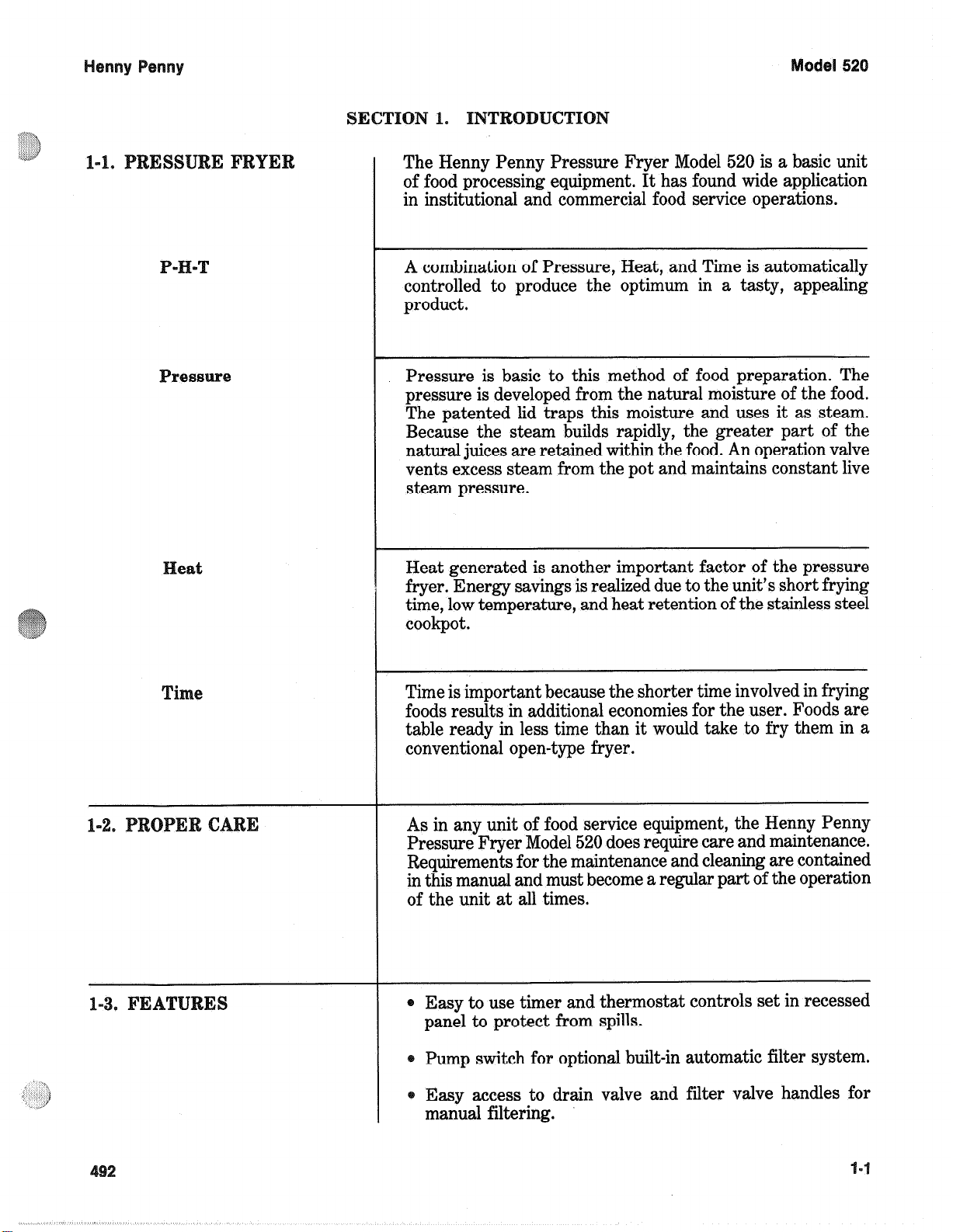
The Henny Penny Pressure Fryer Model 520 is a basic unit
of food processing equipment. It has found wide application
in institutional and commercial food service operations.
A combination of Pressure, Heat, and Time is automatically
controlled to produce the optimum in a tasty, appealing
product.
Pressure is basic to this method of food preparation. The
pressure is developed from the natural moisture of the food.
The patented lid traps this moisture and uses it as steam.
Because the steam builds rapidly, the greater part of the
natural juices are retained within the food. An operation valve
vents excess steam from the pot and maintains constant live
steam pressure.
eat
e
Heat generated is another important factor of the pressure
fryer. Energy savings is realized due to the unit’s short frying
time, low temperature, and heat retention of the stainless steel
cookpot.
Time is important because the shorter time involved in frying
foods results in additional economies for the user. Foods are
table ready in less time than it would take to fry them in a
conventional open-type fryer.
As in any unit of food service equipment, the Henny Penny
Pressure Fryer Model 520 does require care and maintenance.
Requirements for the maintenance and cleaning are contained
in this manual and must become a regular part of the operation
of the unit at all times.
@ Easy to use timer and thermostat controls set in recessed
panel to protect from spills.
Pump switch for optional built-in automatic filter system.
Easy access to drain valve and filter valve handles for
manual filtering.
Page 7
1-3. FE
One piece cast aluminum lid with stainless steel liner for
easy cleaning.
Single-action front lid latch allows one-handle opening and
closing.
Latch mechanism locks lid in closed position when under
pressure.
Automatic pressure release valve.
Removable side panels provide easy access for servicing.
1-4. SAF
The Henny Penny Pressure Fryer has many safety features
incorporated. However, the only way to ensure safe operation
is to fully understand the proper installation, operation, and
maintenance procedures. The instructions in this manual have
been prepared to aid you in learning the proper procedures.
Where information is of particular importance or safety
related, the words DANGER, WARNING, CAUTION, and
NOTE are used. Their usage is described below.
The word DANGER indicates an imminent hazard
which will result in highly serious injury such as second
or third degree burns, loss of sight, and other permanent injuries.
I
The word WARNING is used to alert you to a
procedure, that if not performed properly, might cause
personal injury, such as burns and/or loss of sight, and
damage to the fryer.
The word CAUTION is used to alert you to a procedure
that, if not performed properly, may damage the fryer,
or product.
The word NOTE is used to highlight especially important information.
Page 8
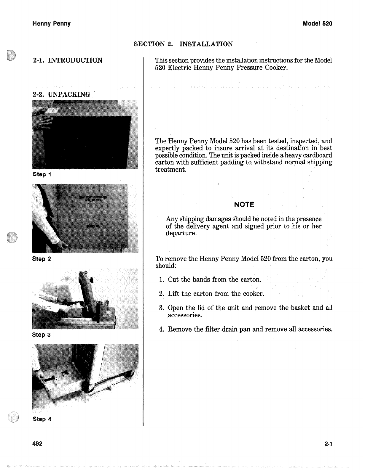
This section provides the installation instructions for the Model
520 Electric Henny Penny Pressure Cooker.
The Henny Penny Model 520 has been tested, inspected, and
expertly packed to insure arrival at its destination in best
possible condition. The unit is packed inside a heavy cardboard
carton with sufficient padding to withstand normal shipping
treatment.
Any shipping damages should be noted in the presence
of the delivery agent and signed prior to his or her
departure.
To remove the Henny Penny Model 520 from the carton, you
should:
1. Cut the bands from the carton.
2. Lift the carton from the cooker.
3. Open the lid of the unit and remove the basket and all
accessories.
4. Remove the filter drain pan and remove all accessories.
Page 9
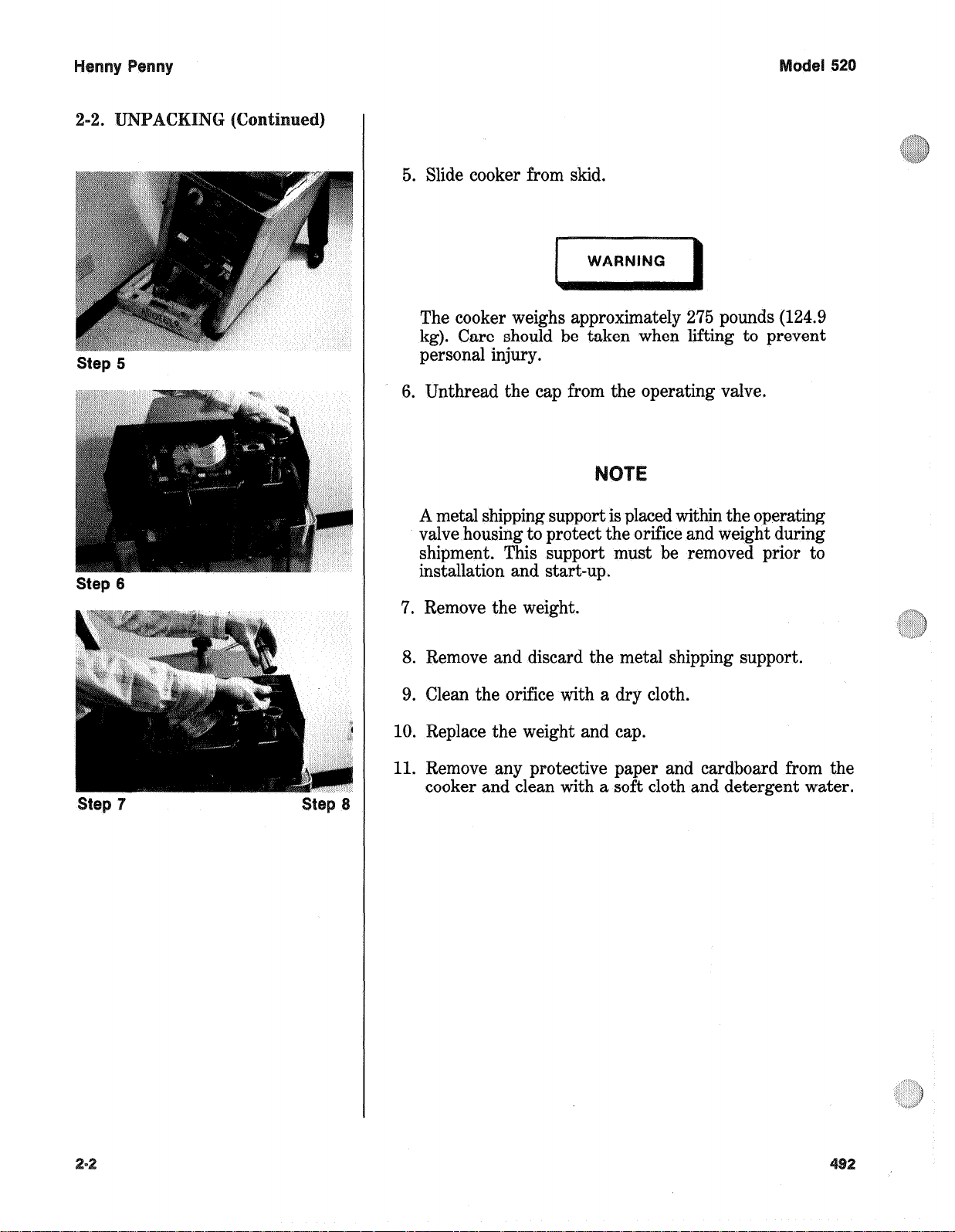
Step 5
Step 6
5. Slide cooker from skid.
The cooker weighs approximately 275 pounds (124.9
kg). Care should be taken when lifting to prevent
personal injury.
6. Unthread the cap from the operating valve.
A metal shipping support is placed within the operating
valve housing to protect the orifice and weight during
shipment. This support must be removed prior to
installation and start-up.
7. Remove the weight.
8. Remove and discard the metal shipping support.
9. Clean the orifice with a dry cloth.
10. Replace the weight and cap.
11. Remove any protective paper and cardboard from the
cooker and clean with a soft cloth and detergent water.
Page 10
odd
520
For proper operation, the cooker should be level from side to
side and front to back. Using a level placed on the flat areas
around the cookpot collar, adjust the leveling bolts or casters
until the unit is level.
-4. VE
The fryer should be located with provisions for venting into
an adequate exhaust hood or ventilation system. This is
essential to remove frying odors and steam exhaust.
Ventilation must conform to local and national codes.
Consult your local building authority and building
codes.
Each fryer is provided with either a 12 AWG (3.3 mm), 4 or
5 conductor power supply cord, 6 feet (1.8 meters) long or a
junction box. The power supply cord is not provided with an
attachment plug for connection to the power point. An attachment plug conforming to local electrical requirements is to be
provided by the installer. Installation of the attachment plug
to the power supply cord conductors should be as follows:
1. Line conductors - color code black/red/white/blue.
2. Grounding conductor - green or green with yellow stripes.
3. Fryers are wired for installation on three phase 208 or
240 volts, three phase source of supply, 20 amps minimum
ampacity. Refer to the data plate installed on the left side
of the fryer for electrical ratings.
Model 520 Electric fryer with built-in filtering system.
1. 240 VACs - 3 phase, 6,000 watts - 12.5 amps
208 VACs - 3 phase, 6,000 watts - 16.6 amps
2. Product capacity 8 lbs. (3.6 kg)
Shortening capacity 30 lbs., 4 gallons or 15 liters
3. Operating pressure 12 PSI (82.7 KPa)
Safety relief - 14.5 PSI (99.9 KPa)
2-3
Page 11
Y
et
52
\
Page 12

Henny Penny Model 520
SECTION 3. OPERA TION
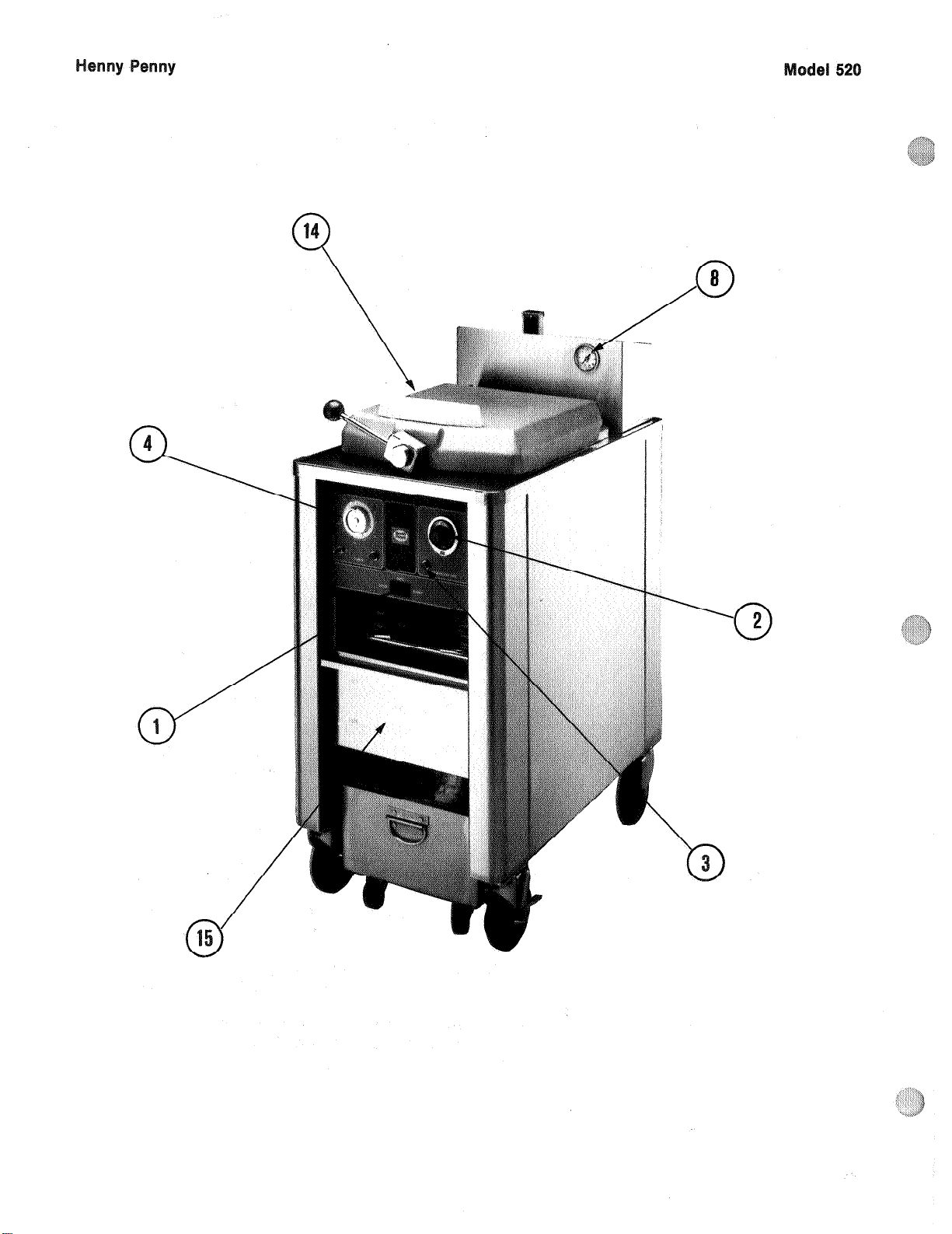
3-1. OPERA TING CONTROLS
Item Description Function
1 Main Power Switch A three way rocker switch with a center off position. Pressing
with Built- In Indicator the left side of the rocker switch (COOK position) operates the
Lights fryer, and the amber light illuminates. No light is visible when
the switch is in the OFF position. T o filter, press the right side
of the rocker switch (PUMP position) to operate the pump
motor, and the red light illuminates.
2 Single Stage An electromechanical device used to regulate temperature.
Thermostat To set the desired cooking temperature, turn the thermostat
knob clockwise.
3 Temperature Light Illuminates when the shortening temperature is below the
set-point temperature. The light goes off when the shortening
reaches the set-point temperature.
4 Timer An electromechanical device that controls the length of the
cooking cycle. The timer controls the operation of the solenoid
valve and automatically resets at the end of the cooking time.
Set the desired cooking time by turning the grayknob clockwise
until the arrow points at the desired cooking time. Pushing on
the red button, activates the timing cycle and closes the solenoid. The red arrow times down to zero (0), while the black
arrow remains at the preset time. When the red arrow reaches
zero (0), it automatically goes back to the preset time. Also, the
solenoid opens, releasing the pressure inside the frypot.
A. Set gray knob to desired time.
B. Push red button to start timing cycle and build pressure.
C. When red arrow reaches zero (0), it resets to preset time
and pressure is released.
5 End of Cooking Cycle A. The timer buzzer sounds, the solenoid valve opens to
release pressure, and the timer resets.
B. Move the timer switch to the OFF position.
6 Dead W eight V alve Maintains a constant level of steam pressure within the frypot.
Assembly Excessive steam pressure is vented through the exhaust stack.
NOTE
Remove the dead weight cap, and clean the cap, weight,
and orifice once a day to prevent over-pressurization inside
the frypot. See section 5-16.
402 3-1
Page 13
Henny Penny Model 520
Item Description Function
7 Safety Relief V alve The safety relief valve is set at 14.5 PSI (99.9 KPa). In the
event that the dead weight valve becomes clogged, the safety
valve releases excessive pressure, keeping the frypot at a
maximum of 14.5 PSI (99.9 KPa). If this occurs, turn the main
power switch to the OFF position to release all pressure from
the frypot. Also, clean the dead weight valve at this time.
DO NOT pull the Safety Relief Valve Ring, or severe burns
will result.
8 Pressure Gauge Indicates nominal pressure within the frypot. This gauge is not
used to calibrate the dead weight assembly . Operating pressure
of the dead weight assembly is preset at the factory .The gauge
is used as an indication of pressure build up within the frypot.
9 Solenoid V alve An electromechanical device that causes pressure to be held in
the frypot. The solenoid valve closes at the beginning of the
cooking cycle and automatically opens at the end of the cooking
cycle.
10 Drain V alve A two way ball valve, normally in the CLOSED position. T o
open the drain, pull the handle slowly outward, away from the
fryer . This releases the oil from the frypot into the filter drain
pan. Push it back in to close the valve.
DO NOT open the drain valve while frypot is under
pressure. Hot shortening exhausts from this valve.
Severe burns will result.
11 Drain Interlock Switch A microswitch that provides protection for the frypot in case the
operator drains shortening from the frypot while the main
switch is in the POWER position. The switch is designed to
automatically remove power from the heating elements when
the drain valve is open.
12 Filter V alve A two way ball valve which operates in conjunction with the
filtering system. W ith the handle in the open position (handle
facing vertical by turning it counterclockwise) and the main
power switch in the PUMP position, this valve directs the
filtered shortening from the drain pan back to the frypot. T o
close the filter valve, turn it clockwise to the horizontal position.
3-2 402
Page 14
el
520
ke
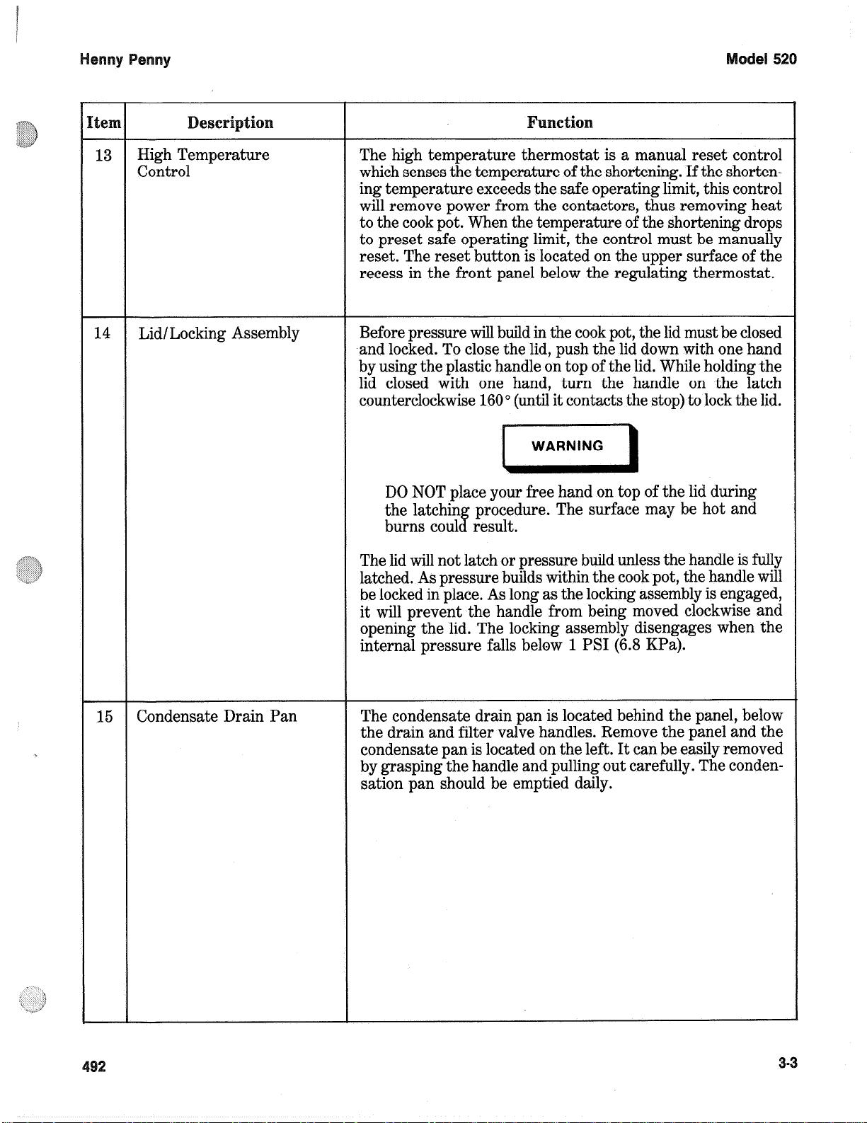
High Temperature
Control
Lid/Locking Assembly
Fun~tio~
The high temperature thermostat is a manual reset control
which senses the temperature of the shortening. If the shorten-
ing temperature exceeds the safe operating limit, this control
will remove power from the contactors, thus removing heat
to the cook pot. When the temperature of the shortening drops
to preset safe operating limit, the control must be manually
reset. The reset button is located on the upper surface of the
recess in the front panel below the regulating thermostat.
Before pressure will build in the cook pot, the lid must be closed
and locked. To close the lid, push the lid down with one hand
by using the plastic handle on top of the lid. While holding the
lid closed with one hand,. turn the handle on the latch
counterclockwise 160 o (until it contacts the stop) to lock the lid.
DO NOT place your free hand on top of the lid during
the latching procedure. The surface may be hot and
burns could result.
15
Condensate Drain Pan
The lid will not latch or pressure build unless the handle is fully
latched. As pressure builds within the cook pot, the handle will
be locked in place. As long as the locking assembly is engaged,
it will prevent the handle from being moved clockwise and
opening the lid. The locking assembly disengages when the
internal pressure falls below 1 PSI (6.8 KPa).
The condensate drain pan is located behind the panel, below
the drain and filter valve handles. Remove the panel and the
condensate pan is located on the left. It can be easily removed
by grasping the handle and pulling out carefully. The condensation pan should be emptied daily.
3-3
Page 15
Henny Penny Model 520
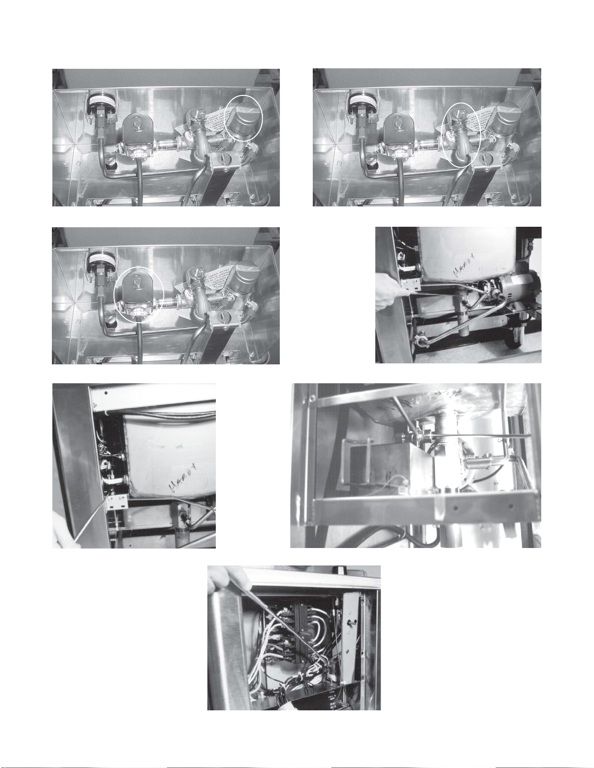
Item 6 Item 7
Item 9 Item 10
Item 11 Item 12
Item 9
3-4 101
Page 16
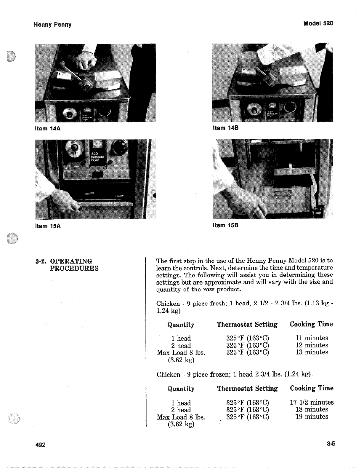
The first step in the use of the Henny Penny Model 520 is to
learn the controls. Next, determine the time and temperature
settings. The following will assist you in determining these
settings but are approximate and will vary with the size and
quantity of the raw product.
Chicken - 9 piece fresh; 1 head, 2 l/2 - 2 3/4 lbs. (1.13 kg -
1.24 kg)
1 head
2 head
Max Load 8 lbs.
(3.62 kg)
Chicken - 9 piece frozen; 1 head 2 3/4 lbs.
tit
1 head
2 head
Max Load 8 lbs.
(3.62 kg)
325°F (163°C)
325 “F (163 “C)
325 “F (163 “C)
T
325 “F (163 “C)
325 “F (163 “6)
325 “F (163 “C)
,’
etti
11 minutes
12 minutes
13 minutes
(1.24 kg)
c
17 l/2 minutes
18 minutes
19 minutes
Page 17
del
52
The following procedures should be followed in the initial
start-up of the fryer and each time the fryer is brought from
a cold or shut down condition back into operation.
1. Check to see that all control switches are turned OFF.
2. Be sure that the drain valve and filter valve are closed.
3. Remove the wire basket from the cook pot and leave the
lid open.
4. Fill the cook pot with shortening to level indicated. The
level indication is the maximum shortening level when hot.
5. Connect the power to the fryer.
6. Move the main power switch to the COOK position.
7. Turn the thermostat knob to the desired cooking
temperature. The temperature light will go on.
8. When the shortening has reached the desired cook
temperature, the temperature indicating light will be off.
9. Thoroughly stir the shortening to stabilize’the temperature
throughout. Make sure that the shortening at the bottom
of the pot is agitated and evenly heated.
10. After the shortening temperature has stabilized for a
minimum of 30 minutes, check the shortening temperature
using a good deep fat thermometer (Henny Penny part
no. 121006).
11. Lower the empty basket into the cook pot (food will be
added later).
12. Select the desired cooking time. You are ready to start
cooking.
NOTE: The overall operation of the 520 Fryer is no
different than our present Model 500 or Model
600 Pressure Fryers.
1. It is recommended that a high quality liquid frying shortening be used in the pressure fryer. Some low grade shortenings have a high moisture content and will cause foaming
and boiling over.
2. If a solid shortening is used, it must be melted to a liquid
first, then poured into the frypot. Attempting to melt a
shortening in the frypot may cause burning or scorching
of the fresh shortening.
“I
‘+I
Page 18
Step 3
el 520
Gloves should be worn and care must be taken when
pouring hot shortening into the unit. Severe burns could
result. Also, when adding fresh shortening to existing
shortening, care must be taken to avoid splashing.
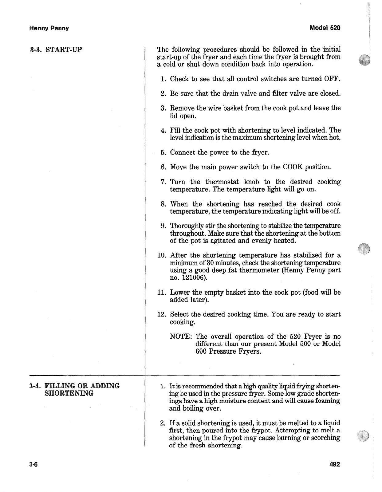
3. Cold shortening should be filled approximately 112 inch
below the bottom level of the level indicator line. The
shortening will expand when heated.
3-5. COOKING
1. Before dropping the product into the basket, make certain
that the shortening is at the correct cooking temperature
for the type of product. Also, check that the temperature
light is OFF. Once the product has been prepared, you are
ready to cook. Place the basket in the cook pot a few
seconds before placing the product in the basket.
2. Place the product into the submerged basket by first
dropping in the larger pieces. This gives the larger and
more difficult pieces a few .extra seconds to cook in the
shortening. Continue to place the remaining product in
the basket.
3. Lift the basket slightly out of the shortening and shake
it, causing the pieces to separate. Return the basket to
the shortening. Doing this will prevent white spots on the
finished product.
4. Remove the basket handle and close the lid quickly. Latch
the lid as previously described.
5. Activate the time as previously described. Within a few
minutes, the pressure gauge will increase to the operating
zone.
6. At the end of the cooking cycle, the fryer will automatically
depressurize. Also the timer light will go off and the timer
will automatically reset.
7. After the pressure drops to 0, open the lid latch assembly
by turning the handle clockwise 160 O.
Page 19

Henny Penny Model 520
3-5. COOKING PROCEDURES 8. Raise the lid promptly to allow most of the condensation
(Continued) on the lid to drain down and out through the drain channel.
Do not let the lid slam up against the back stop. This could
damage the hinge assembly . This will also allow condensation to
drop back into the shortening.
NOTE: The condensation opening behind the pot needs to be
kept clear of obstructions. Failure to do so will cause the
moisture to back up onto the countertop.
9. Insert the handle into the basket, lift the basket out of the
shortening, and hang it on the side of the cook pot to drain.
Allow the product to drain approximately 15 seconds before
placing it into the tray .
10. The fryer will automatically recover to the preset cooking
temperature. Once the thermostat indicator light goes out, you
can begin the next cook cycle. If filtering of shortening is
desired at this time, refer to the next section.
NOTE: When no additional cooking is intended within 30 minutes
of the previous cook cycle, it is recommended to reduce
the shortening temperature (by turning the thermostat
knob counterclockwise) to 275
o
F (135o C).
Four product controls, use the “C” (up and down)
buttons and select Idle. The controls will automatically
o
reduce the temperature to 250
F (121o C).
3-6. FIL TERING THE Cooking breaded products requires frequent filtering to keep
SHORTENING the shortening clean. The shortening should be filtered after
every three to six cooking cycles. For the best quality product, do
not exceed six cook cycles without filtering.
1. Turn the thermostat and the main power switch to the OFF
position. Remove and clean the fry basket in soap and water .
Rinse thoroughly .
NOTE: For best results, filter shortening at normal cooking
temperature.
2. Use a metal spatula to scrape build up from sides of the frypot.
When using the pot scraper, do not damage the capillary line on
the thermostat, or the high limit control. Also, do not scrape the
heating elements, or damage to elements could result.
3-8 600
Page 20
el 520
The filter pan must be in the
the drain valve. This will prevent the splashing of the
hot shortening as it drains into the filter drain pan
which would cause burns.
3. Open the drain valve by pulling it forward slowly. This
will prevent excessive splashing of the hot shortening as
it drains into the filter drain pan.
4. As the shortening drains from the fry pot, use bushes
(Henny Penny part no. 12105) to scrape and clean the sides
of the fry pot and the heating elements. If the drain fills
with breading, use the white brush to push the breading
into the filter pan.
5. When all of the shortening has drained, scrape or brush
the sides and the bottom of the cook pot.
6. Rinse the cook pot as follows:
A. Close the drain valve by pushing the handle inward.
B. Open the filter valve by turning the handle counter-
clockwise.
proper position beneath
Hold the lid closed so that the very first surge of the
shortening will not splash up or over the top of the cook
pot’. Severe burns will result.
C. Move the main power switch to the PUMP position.
Carefully open the lid to see if shortening is returning properly. Fill cook pot l/3 full, then turn off the
mum. . .
If there are air bubbles coming up in the shortening,
it is possible that the filter connecting union on the filter
tube line is not tightened properly. If so, turn off the
pump and use gloves to tighten the union. *This union
will be hot and severe burns will result.
Page 21
el
520
3-6. FILTERING THE
S TENING (Co~ti
D. Wash down and scrub the sides of the cook pot. Use
“L” brush to clean the heating elements.
E . After the sides and bottom are cleaned, open the drain
valve.
7. Pump all the shortening out of the filter pan and back into
the cook pot. Close the lid during the first surge of
pumping.
8. When the pump is pumping air only, the shortening in the
fry pot will appear to be boiling. Close the filter valve first
and then move the main power switch from PUMP to
OFF. This will keep the filter pump and lines from filling
up with shortening.
Note: When the appearance of boiling occurs, immediately
close the filter valve, then turn the pump off. This will
prevent aeration of the shortening, therefore increasing
shortening life.
9. Check the level of the shortening in the cook pot. Add fresh
shortening, if necessary, until it reaches the level indicator
line on the rear wall of the cook pot.
GING T
ENVELOPE
F~LTE
NOTE: Approximately 10 to 12 filterings can be made with
one filter paper envelope, depending on several
conditions; the quantity and type of product fried and
filtered, the type of breading used, and the amount
of crumb accumulation left inside the filter drain pan.
When the filter screen assembly and filter paper
become clogged and pumping flow rate slows down,
clean the screen assembly and change the filter
envelope. See procedure on page 3-11.
10. After completing the filtering operation, empty and
replace the condensation drain pan.
11. If cooking is to be continued at this time, move the main
power switch back to the COOK position and allow time
for reheating of the shortening.
The filter envelope should be changed after lo-12 filterings
or whenever it becomes clogged with crumbs. Proceed as
follows:
1. Move the main power switch to the OFF position.
2. Remove and empty the condensation drain pan.
3. Disconnect the filter union and remove the filter drain pan
from beneath the fry pot. The filter drain pan is provided
with casters for ease of movement.
Page 22

Step 3
FILTE
ti~~e~)
This union will be hot. Use protective glove or cloth
to prevent burns.
4. Lift the screen assembly from the drain pan.
5. Wipe the shortening and crumbs from the drain pan. Clean
the drain pan with soap and water. Thoroughly rinse with
hot water.
Step 6
6. Unthread the suction standpipe from the screen assembly.
7. Remove the crumb catcher. Clean thoroughly with soap
and water. Rinse thoroughly with hot water.
Page 23

ENVELOPE (Co~ti~~ed)
Step 8
Step 10
8. Remove filter clips and discard the filter envelope.
9. Clean the top and bottom filter screen with soap and
water. Rinse thoroughly with hot water.
Be sure that the filter screens, crumb catcher, filter
clips, and the suction standpipe are thoroughly dry
before assembly of filter envelope, as water will dissolve
the filter paper.
Assemble the top filter screen to the bottom filter screen.
10.
11. Slide the screens into a clean filter envelope.
tep 11
tep 12
12. Fold the corners in and then double fold the open end.
Clamp the envelope in place with two filter retaining clips.
13.
Replace the crumb catcher screen on top of the filter paper.
14.
Screw on the suction standpipe assembly.
Place complete filter screen assembly back into filter drain
15.
pan. Slide pan back into place beneath the fryer.
Connect the filter union by hand. Do not use a wrench to
16.
tighten.
Slide the condensation drain pan back into place. The fryer
17.
is now ready to operate.
Page 24

Henny Penny Model 520
3-8. CLEANING THE FR YPOT T aste the cold shortening every day for flavor. Watch the shortening
for foaming during the cook cycle. Discard the shortening as soon
as it shows signs of foaming. Drain and clean the frypot as follows:
1. Turn the power switch to OFF .
Place the filter drain pan under the drain valve to prevent
splashing or spilling of hot liquids. Failure to do so, results in
splashing and severe burns.
2. Pull out drain valve handle to drain hot shortening from frypot.
3. Close the drain valve, and discard the shortening in filter pan.
Install the filter drain pan under the fryer, leaving out the filter
screen assembly .
4. Fill the frypot to the level line with hot water. Add 2 to 4
ounces (6 to 12 ml) of fryer cleaner (Henny Penny part no.
12101) to the water and mix thoroughly . The fry basket can be
placed inside the frypot for cleaning.
Always wear safety goggles or face shield and rubber gloves
when cleaning the frypot. The highly alkaline cleaning solution
should not contact eyes or skin, or severe burns will result.
Carefully read the instructions on the cleaner . If solution
contacts your eyes, rinse thoroughly with cool water and see a
physician immediately .
5. Standard Controls: Set thermostat to 195
o
F (91o C) and turn
the power switch to POWER position.
Electronic Controls: Use the up and down buttons to select
the Clean mode. The controls will automatically heat the
solution up to 190
o
F (88o C).
NEVER PRESSURIZE TO CLEAN. Leave the lid open.
W ater under pressure is super heated and causes severe burns.
600 3-13
Page 25

Henny Penny Model 520
3-8. CLEANING THE FR YPOT 6. When the set temperature is reached, turn unit off.
(Continued)
Watch cleaning solution constantly to make sure it does NOT
boil over causing damage to controls.
If the cleaning solution starts to foam and boil over, DO NOT
CLOSE THE FRYER LID, severe burns could result.
7. Let the cleaning solution stand for 15 to 20 minutes, with the
unit turned off.
8. Use fryer brush (Henny Penny part no.12105), to scrub the
inside of the frypot, the lid liner, and the counter top of the fryer.
Never use steel wool, it deteriorates the stainless steel.
Do not use the cleaning solution on the lid or the lid hinge.
These aluminum parts will corrode if the PHT cleaner contacts
them. Also, Do not use abrasive cleaners, or cleaner containing
chlorine, bromine, iodine, or ammonia chemicals on the stainless
steel. Deterioration of the stainless steel will result.
9 Open the drain valve and drain the cleaning solution from the
frypot into the drain pan and discard.
10. Replace the empty drain pan, close the drain valve, and refill the
frypot with hot water to proper level.
1 1. Add approximately 4 ounces of distilled vinegar and reheat the
vinegar solution to 195
o
F (91o C), or use the Clean mode on
electronic controls.
12. Using a clean brush, scrub the interior of the frypot and lid liner.
This neutralizes the alkaline left by the cleaning compound.
13. Drain the vinegar rinse water and discard.
14. Rinse down the frypot, using clean hot water .
15. Thoroughly dry the drain pan, and the frypot interior .
NOTE: Make sure the inside of the frypot, the drain valve
opening, and all the parts that will come in contact with the
new shortening, are as dry as possible.
16. Replace the clean filter screen assembly in the drain pan and
install under fryer .
17. Refill the fryer with fresh shortening.
3-14 700
Page 26

TING
el 52
4-1.
4-2. T
UCTI
This section provides troubleshooting information in the form
of an easy to read table.
If a problem occurs during the first operation of a new fryer,
recheck the installation section of this manual.
Before troubleshooting, always recheck the operating
procedures.
To isolate a malfunction, proceed as follows:
1. Clearly define the problem (or sympton) and when it
occurs.
2. Locate the problem in the troubleshooting table.
3. Review all possible causes. Then, one-at-a-time, work
through the list of corrections until the problem is solved.
WARNING
I
Refer to the maintenance procedures section to safely
and properly make the checkout and repair needed. If
maintenance procedures are not followed correctly,
injuries and/or property damage could result.
Page 27

Y
el- 520
roble
Product Color Not
Correct:
A. Too Dark
B. Too Light
cause‘
Temperature too high.
Shortening too old.
@ Shortening too dark.
* Dip solution too strong for
product.
e Breading product too far in
advance.
@ Temperature too low.
I
Correction
e Reduce thermostat setting.
e Check thermostat calibration.
e Remove and replace defective
thermostat.
0 Change shortening.
0 Filter shortening.
0 Taste shortening.
@ Change shortening.
@ Use correct dip solution or
shorten product immersion
time.
@ Bread product closer to actual
frying period.
8 Increase temperature.
Check calibration of
thermostat.
0 Remove and replace defective
thermostat.
6. Product Greasy
Dip solution too weak.
Fryer incorrect preheat.
Frypot overloaded with
product.
Slow fryer heatuplrecovery.
Temperature too low.
Frypot overloaded.
Product not removed from
frypot immediately after
depressurization.
0 Correct dip solution.
@ Allow proper preheat time.
@ Stir shortening prior to
dropping product into frypot.
Reduce cooking load.
@ Refer to heating elements in
the maintenance section.
Replace shortening.
@ Increase thermostat setting.
@ Temperature not recovered
when product was dropped in
frypot basket.
Check thermostat calibration.
Replace thermostat if needed.
Reduce cooking load.
Remove product immediately
after depressurization of the
fryer.
Page 28

Y
el 520
D. Spotted Product
E. Dryness of
Product
Improper separation of the
product.
Product was incorrectly
dipped.
Breading not uniform on the
product.
6 Burned breading particles on
product.
0 Product sticking together.
@ Moisture loss prior to cooking.
Over cooking the product.
Drop product into basket
properly and shake basket
before closing lid.
@ Agitate product during the
dipping procedure.
c Sift breading regularly.
a Separate product during
breading.
@ Filter the shortening more
frequently.
e Separate product prior to
pressure cooking.
0 Use fresh product.
0 Keep product covered with a
moist cloth to reduct
evaporation.
0 Reduce cook time.
* Reduce cook temperature.
Product Flavor
(Taste):
A. Salty taste
B. Burned Taste
Low operating pressure.
Too small of a load being
cooked.
Breading miirture is too salty.
Marination mixture too
concentrated.
Incorrect choice of breading.
@ Burned shortening flavor.
Shortening needs filtering.
0 Check pressure gauge reading,
check, for pressure leaks.
e Increase quantity to obtain
correct operating pressure and
product quality.
Sift breading after each use.
0 Incorrect breading mixture.
e Discard old breading.
e Reduce the concentration of
the marination mixture.
@ Use breading designed for the
desired product.
e Replace shortening.
Filter shortening more
frequently.
Frypot not properly cleaned.
Drain and clean frypot.
Page 29

ode1
520
C. Bland Taste
D. Rancid Taste
Raw product not fresh.
@ Breading mixture incorrect
for product (spice content too
low).
0 Cooking temperature too high
(spice flavor lost).
Breading does not adhere to
product.
@ Shortening too old.
8 Non compatible products
cooked within the same
shortening.
Infrequent filtering.
Use fresh raw products.
Use breading designed for
desired product.
@ Use correct temperature for
breading used.
@ Use correct dip and breading
and use correct procedure for
the product.
0 Replace shortening and follow
recbmmended care and use of
shortening.
@ Replace shortening.
* Use compatible products and
follow recommended care and
use of shortening.
0 Replace shortening and follow
recommended care and use of
shortening.
General:
A. Meat separation
from bone
B. Bone color not
proper
Raw product not fresh.
Incorrect meat cut.
Overcooking.
Raw product contains too
much water.
Product not fresh.
Using frozen product (black
bone).
Improper processing of
product (black bone).
Product not thoroughly
cooked (red bone).
@ Use fresh product.
Use correct meat cutting
procedures.
Reduce cooking time.
Allow product to drain after
marinating.
Use fresh product.
Use fresh product.
Use proper processing
procedure for product.
Increase cooking time.
Page 30

el 520
C. Breading falls
off
D. Product sticking
together
Incorrect breading
procedures.
Product partially frozen
during breading.
@ Improper handling of cooked
product.
* Excessive stirring of product
prior to closing the lid.
Product breaded too long
prior to cooking.
Improper separation
procedures prior to closing the
lid.
Frypot overloaded with
product.
Use correct breading
procedure.
@ Thoroughly thaw the product
before breading.
Handle cooked product
carefully.
0 Separate the product.
Refer to breading and frying
instructions.
0 Separate the product.
@ Reduce the cooking load.
With switch in
POWER position the
fryer is completely
inoperative (NO
POWER)
Improper loading procedure.
Open circuit.
0 Load product in frypot.
Check to see that unit is
plugged in.
Check breaker for fuse at
supply box.
@ Check control panel fuses.
e Check voltage at wall
receptacle.
Check MAIN POWER switch.
Replace if defective.
Check cord and plug.
Check circuit breaker.
Page 31

ode1 520
Pressure will not
exhaust at end of
frying cycle
Operating pressure
too high
Pressure does not
build
Exhaust line from solenoid
valve to expansion tank
clogged.
* Solenoid valve clogged.
* Dead weight clogged.
* Exhaust line to stack clogged.
* Not enough product in fryer
or product not moist.
Metal shipping spacer not
removed from dead weight.
Lid open or not latched.
* Solenoid valve leaking or not
closing.
Dead weight valve leaking.
* Release pressure from frypot;
clean all pressure lines.
* Check and clean solenoid valve.
* Release pressure from frypot;
remove dead weight and clean.
* Clean exhaust line to stack.
* Place proper quantity of moist
product within frypot to
generate steam.
Remove shipping spacer.
* Close and latch lid.
* Check or clean solenoid valve.
* Repaid dead weight valve, per
maintenance section.
Filter motor runs but
pumps shortening
slowly
Main timer not closing
solenoid.
Safety relief valve leaking.
Filter valve not open.
Pump clogged.
Filter screens not properly
assembled.
Filter line connections loose.
Solidified shortening in lines.
I
Filter paper clogged.
Check main timer.
Check and replace if necessary.
Open filter valve.
Remove and clean pump.
Reassemble filter screens.
Tighten all filter line
connections.
Clear all filter lines of solidified
shortening.
Change filter paper.
Page 32

el
52
Motor hums but will
not pump
Shortening will not
heat
Ca~ee
CTIQN (Continued)
Defective motor.
Motor
thermal protector
* Clogged lines or pump.
TENING SEC
Blown fuse or tripped breaker
at supply box or control panel.
Blown fuse at control panel.
Faulty main switch.
correction
Check/replace motor.
* Reset thermal switch.
* Remove and clean pump lines.
* Replace pump seal, rotor and
rollers.
* Reset breaker or replace fuse.
* Check fuse.
* Check main switch.
eating of shortening
too slow
Shortening
overheating
Check cord and plug. Check
power at receptacle.
Faulty contactor.
Faulty thermostat.
Faulty high limit control
switch.
Low or improper voltage.
Weak or burnt out elements.
Points in contactor bad.
Wires loose.
Burnt or charred wire
connection.
Check thermostat
Check cord and plug and power
at wall receptacle.
* Check contactor.
* Check thermostat’.
Check high limit control switch.
Use a meter and check the
receptacle against data plate.
Check heating elements.
Check contactor.
* Tighten.
Replace wire and clean
contactors.
* Calibrate thermostat
* Check faulty thermostat
Check contactor for not
opening.
Check faulty contactor.
Page 33

ING SECTIQN
Foaming or boiling
over of shortening
Shortening will not
drain from fry-pot.
Water in shortening.
Condensation line stopped up.
Improper or bad shortening.
Improper filtering.
* Improper rinsing after
cleaning the fryer.
Drain valve clogged with
crumbs.
Drain valve will not open by
turning handle.
* At the end of frying cycle,
drain shortening and clean
frypot. Add fresh shortening
and check procedure for raising
lid.
* Remove and clean condensation
line.
Use recommended shortening.
* Refer to the procedure
covering filtering the
shortening.
Clean and neutralize the frypot.
Rinse with vinegar to remove
the alkaline then rinse with hot
water and dry frypot.
* Open valve - force cleaning
brush through drain opening.
Replace cotter pins in valve
coupling.
Timer fails to run
Buzzer continues to
buzz
Buzzer will not buzz
Timer will not reset
Timer light out
No power input
Timer set at zero.
Faulty microswitch.
Possible faulty buzzer.
Timer indicator not returning
to zero.
Faulty timer.
Faulty lamp.
Check timer switch
Check timer motor
Set timer indicator to a setting
other than zero.
Check and replace faulty
microswitch.
Check buzzer, replace if. faulty.
* Replace timer.
* Replace timer.
Replace lamp.
Page 34

.
UCTI This section provides procedures for the replacement of the
various parts used within the pressure fryer. Before replacing
parts, refer to the troubleshooting section of this manual. It
will aid you in determining the cause of the malfunction.
WARNING
I
Place power switch in the OFF position, shut off power
at the fuse or breaker box. Failure to do so could result
in electrical shock.
1. Remove two 318” nuts from bottom of side panel,
2. Using a straight blade screwdriver, gently pry side panel
straight up.
3. Slide side panel from unit.
I
Place power switch in the OFF position, shut off power
at the fuse or breaker box. Failure to do so could result
in electrical shock.
Page 35

Step lb
1. Remove four screws securing control panel to unit and
also thermostat knob.
2. Unplug the nine pin connector.
3. Remove two wires from thermostat (wire number 13 &
16) and remove control panel.
Place power switch in the OFF position, shut off power
at the fuse or breaker box. Failure to do so could result
in electrical shock.
1. Follow steps 1, 2 and 3 in
emoval of Control Panel.
emove two screws from the buzzer coil bracket.
‘”
.,,,*i
Page 36

move screw mounting buzzer coil to bracket.
4. Cut wires on old buzzer. (Note: Mark wires before
cutting.)
5. Install new buzzer and splice cut wires.
Place power switch in the OFF position, shut off power
at the fuse or breaker box. Failure to do so could result
in electrical shock.
1. Follow steps 1, 2 and 3 in Removal of Control Panel.
2. Unplug wires from old timer switch. (Note: Mark wires
before unplugging.)
3. Loosen the 9116” retainer nut behind timer switch.
Remove front retainer nut of timer switch and install new
4.
switch.
Page 37

Place power switch in the OFF position, shut off power
at the fuse or breaker box. Failure to do so could result
in electrical shock.
2
1. Follow steps 1,
and 3 in Removal of Control Panel.
2. Remove the two screws securing motor to timer.
3. Cut wires on old motor. (Note: Mark wires before cutting.)
4. Install new motor and splice cut wires.
Place power switch in the OFF position, shut off power
at the fuse or breaker box. Failure to do so could result
in electrical shock.
1. Follow steps 1, 2 and 3 in Removal of Control Panel.
2. Unplug wires from old power switch. (Note:
ark wires
before removing.)
3. Depress retainers on rear of switch and push switch out
towards front of control panel.
. Install new power switch.
Page 38

2a
Place power switch in the OFF position, shut off power
at the fuse or breaker box. Failme to do so could result
in electrical shock.
1. Follow steps 1, 2 and 3 in Removal of Control Panel.
2. Remove two 3/V nuts securing thermostat bracket to
control area.
3. Remove two screws holding thermostat to bracket.
4. On the inside of pot, loosen screws on bracket securing
thermostat bulb.
emove 11116” nut from pot wall and remove thermostat.
6. Install new thermostat in reverse order.
Page 39

el
52
Place power switch in the OFF position, shut off power
at the fuse or breaker box. Failure to do so could result
in electrical shock.
Whenever the thermostat fails to maintain the selected
temperature within f 5 “F (- 15 “C) of the thermostat setting,
it should be calibrated.
To calibrate the thermostat, it is necessary to perform step
increases in the temperature of shortening. Follow this
procedure:
1. Place the main power switch in the POWER position. Be
sure there is shortening in the frypot.
2. Set the thermostat knob to 250°F (121” C).
3. Allow enough time for the shortening to heat. When the
shortening reaches the set temperature on the thermostat,
the indicator light will go off. Usually, it will take no longer
than 15 minutes for the shortening to heat to the set
temperature.
4. Remove the fry basket from the shortening.
5. Stir the shortening with the basket handle.
6. Measure the temperature of the shortening using an
accurate, mercury tube type, deep fat thermometer
capable of measuring temperatures in the 250 “F to 400 “F
(121 “C to 204°C) range. (Henny Penny part number
12106.)
7. Insert the thermometer near the center of the frypot to
a depth of about 3 inches below the level of shortening.
8. Carefully stir the shortening with the thermometer.
9. Allow the mercury in the thermometer to rise to the
temperature of the shortening. Hold the thermometer
straight up and down.
The temperature reading is to be taken just as the
TEMP indicator light goes off. This will give the correct
temperature rather than an override temperature.
10. If the temperature is within 5°F (- 15°C) of the
temperature set on the thermostat, increase the thermostat setting approximately 25 “F (- 4°C). Wait until the
indicator light goes off, then again check the temperature
Page 40

el 520
of the shortening. If it is again within 5 “F (- 15%), the
thermostat does not require calibration.
If the thermometer is accidentally broken, and mercury
and pieces of broken glass fall into the shortening,
discard the shortening and clean the frypot thoroughly.
Mercury is highly poisonous.
11. If the temperature indicated on the thermometer differs
more than 5 “F (- 15 “C), remove the thermostat knob by
pulling it off its stem.
Do not rotate the knob while removing it.
12. Turn the adjustment screw in the center of the hollow
stem, using a small blade screwdriver. If the thermometer
reading was higher than the setting, rotate the screw
clockwise. If lower, counter-clockwise. For example:
setting:
reading:
adjustment:
After adjusting the screw, install the knob and reset the
13.
thermostat to 250°F (121 “C). Again, measure the
temperature of the shortening with the deep fat thermometer. Wait a few moments for the shortening to reach
the 250 “F (121 “C) temperature setting, indicated on the
thermometer. The indicator light should go off when the
temperature reaches 250 “F (121 “C). Readjust screw if
necessary.
14. Set the thermostat to 275°F (135 “6).
250 “F (121 “C)
275 “F (135 “C)
114 turn clockwise.
I
15. Check the temperature of the shortening when the
indicator light goes off.
16. If the temperature measured on the thermometer is not
within 5 “F (- 15 “C) of the thermometer setting, adjust
for the correct temperature as in steps 12 and 13 of this
procedure.
Once the thermostat has been calibrated and set at the
desired cooking temperature, do not use the thermostat
to turn the fryer ‘off. Use the ON-OFF switch.
Page 41

This high temperature control is a manual reset control
which senses the temperature of the shortening. If the
shortening temperature exceeds the safe operating
limit, this control switch will open and shut off the heat
to the frypot. When the temperature of the shortening drops to the safe operating limit, the control must
manually be reset.
Before replacing a high temperature limit control, check to
see that its circuit is closed.
The shortening temperature must be below 330°F
(192°C) to accurately perform this check.
1. Remove electrical power supplied to the fryer.
Place POWER/OFF/PUMP switch in the OFF
position, and unplug the power cord or open the wall
circuit breaker, or electrical shock could result.
2. Remove the control panel.
3. Remove the two electrical wires from the high
temperature limit control.
4. Check for continuity between the two terminals after
resetting the control. If the circuit is open, replace the
control, then continue with this procedure. (If the circuit
is closed, the high limit is not defective. Reconnect the two
electrical wires.)
Before following these steps,
POWER/OFF/P~P switch in the OFF position, and
unplug the power cord or open the wall circuit breaker,
or electrical shock could result.
place
1. If the tube is broke&i or cracked, the control will open,
shutting off electrical power. The control cannot be reset.
Page 42

2. Drain shortening from the frypot.
3. Remove control panel.
4. Loosen small inside screw nut on capillary tube.
5. Remove capillary bulb from bulb holder inside the fry-pot.
6. Straighten the capillary tube.
I
7. Remove larger outside nut that threads into pot wall.
8. Remove the two screws that secure the high limit to the
high limit bracket.
9. Remove defective control from control panel area.
10. Insert new control and replace screws.
11. Uncoil capillary line, starting at capillary tube, and insert
through frypot wall.
To avoid electrical shock or other injury, the capillary
line must run under and away from all electrical power
wires and terminals. The tube must never be in such
a position where it could accidentally touch the
electrical power terminals.
Page 43

Step 3
Place power switch in the OFF position, shut off power
at the fuse or breaker box. Failure to do so could result
in electrical shock.
1. Drain the shortening.
2. Remove the thermostat and high limit bulb holder from
the heating element inside the frypot.
3. Remove the heating element wires from the contactor.
Label each so it can be replaced in the same position on
the new element.
4. Slide the element spreaders to the center of the heating
element.
Remove the brass nut and washer, which secure the ends
5.
of the element through the frypot wall.
Remove the heating element from the frypot by lifting the
6.
far end and sliding it up and out toward the rear of the
frypot.
Always install new rubber 0 rings (2) when installing
heater elements.
7. Install new heating element with new rubber 0 rings (2)
mounted on terminal ends, and spreaders loosely mounted
in the center of the stacked elements.
8. Replace the heating elements, terminal end first at
approximately 45” angle, slipping the terminal ends
through the front wall of the frypot.
Replace the brass nut and washer on the heating element
9.
terminals. Tighten the brass nuts to 30 foot lbs. of torque.
10. Move the element spreaders from the center of the
element, and tighten.
11. Replace the thermostat and high limit bulb holder and
tighten screw which holds the bulb in place.
econnect the wires to the appropriate terminal as labeled
when they were removed.
13. Replace the front control panel.
Page 44

14. Conned the power cord to the wall receptacle or close wall
circuit breaker.
Heating element should never be energized without
shortening in the frypot, or damage to element could
result.
15. Replace the shortening in the fry-pot.
If either contactor is defective it must be replaced as follows:
WARNING
I
Remove electrical power supplied to the fryer, by
unplugging or opening the wall circuit breaker, or
electrical shock could result.
1. Remove only those wires directly connected to the
contactor being replaced. Label the wires.
2. Remove the two mounting screws on the base plate and
remove contactor.
3. Install the new contactor and tighten the two mounting
screws.
4. Connect the labeled wires to their respective positions.
5. Install the control panel.
connect power to the fryer and test the fryer for proper
operation.
Page 45

Place power switch in the OFF position, shut off power
at the fuse or breaker box. Failure to do so could result
in electrical shock.
1. Remove retaining ring from hinge pin.
I
2. Using a punch and hammer, drive hinge pin out from
spring.
3. Remove old spring.
4. Remove stops from cam.
oosen 318” nuts from rear shroud, remove nut from
pressure gauge, and remove shroud.
Page 46

5-13.
Step
EPLA
INGE
(CQntin~e~)
5b
6. Position new spring as shown in illustration at left.
tep 6a
Spring must be in this position to accurately install lid
hinge spring.
7. Open lid to rear of unit as far as possible.
8. Using a punch and hammer, drive hinge pin back into lid
and spring.
9. Reattach lid stops and rear shroud.
Page 47

Henny Penny Model 520
5-14. REPLACEMENT OF LID
GASKET
Place power switch in the OFF position, pull fuse or turn off
wall circuit breaker, or electrical shock could result.
1. Using a straight blade screwdriver, pry one corner of gasket
out from liner.
2. Pull gasket from lid.
Step 1
3. Clean gasket and gasket seat with soap and hot water .
4. Reinstall lid gasket with “good” side facing out, or install new
gasket.
NOTE
Reverse lid gasket every 90 days to keep gasket in good
Step 2
condition.
5-15. LID LA TCH The cam shaft and latch plate should be lubricated every 90 days to
LUBRICATION prevent early wear and failure of latch parts.
1. Using spindle lube, part number 12124, place a small amount of
spindle lube in the top portion of the latch plate. See Figure 1.
Figure 1
2. Using spindle lube, part number 12124, place a small amount of
spindle lube on the cam shaft. See Figure 2.
Figure 2
5-14 101
Page 48

Henny Penny Model 520
5-16. DEADWEIGHT VALVE
ASSEMBLY
Do not attempt to remove the valve cap while the fryer is in
operation, or severe burns or other injuries could result.
The deadweight valves are located behind the lid. The valve, left of
th e pressure gauge, is a 14 1/2 lb. (999 mbar) safety relief valve, and
the one on the right is the operating valve.
V alves are working properly , when the pointer on the gauge is in the
Deadweight Valve “OPERA TING ZONE” (green area). The gauge pointer should
not normally exceed the operating zone. If the pressure builds to
14-1/2 lbs.(999 mbar), the safety relief valve will open to release
steam pressure from inside cookpot.
CAP ORIFICE WEIGHT
DO NOT MANUALL Y ACTIVA TE THE SAFETY
RELIEF VAL VE. Hot steam will be released from valve
when ring is pulled. Keep away from safety valve exhaust,
or severe burns could result.
1. A T THE END OF EACH DAY’S USAGE OF THE
FR YER, THE OPERA TING VAL VE MUST BE
CLEANED. The fryer must be OFF and the pressure
released. Open the lid and then remove the dead weight
valve cap and dead weight.
Failure to clean the operating control valve daily could
result in the fryer building too much pressure. Severe
injuries and burns could result.
2. Wipe both the cap and weight with a soft cloth. Make
certain to thoroughly clean inside cap, the weight seat, and
around valve orifice.
3. Dry the parts and replace immediately to prevent damage
or loss.
402 5-15
Page 49

Henny Penny Model 520
5-17. REMOVAL & CLEANING The safety relief valve should be cleaned once a year.
OF SAFETY RELIEF VALVE
SAFETY VALVE
DO NOT ATTEMPT TO REMOVE V AL VE WHILE
FR YER IS OPERA TING, or severe burns or other injuries
could result.
1. Using 3/8” socket, remove the 4 nuts securing back shroud.
2. Loosen nut on pressure gauge, and pull the back shroud from
fryer .
Step 1
Step 2
3. Unscrew Deadweight cap and remove cap and weight.
4. Use a wrench to loosen the valve from the pipe tee, turn
counterclockwise to remove.
5. Clean the inside of the pipe tee with hot water.
6. Immerse the safety relief valve in a soapy water solution
for 24 hours. Use a 1 to 1 dilution rate. The valve cannot
be disassembled. It is factory preset to open at 14 1/2
pounds of pressure. If it does not open or close, it must
be replaced.
DO NOT DISASSEMBLE OR MODIFY THIS VAL VE.
T ampering with this valve could cause serious injuries and also
voids agency approvals and appliance warranty .
Step 3
5-16 402
Page 50

MODEL 52OC
HENNY PENNY CORP.
EATON, OH 45320
MOTOR
PUMP
~-~-
I I ‘II I-
I I
CONNECTORS
-- !A
I- I
I
11
I I
12131415161718191
I I I I I
1A 2A 3A 4A 5A 6A 7A 8A 9A
I
I I I I
I
I
I
I
HI-LIMIT
THERMOSTAT
I
I
I
I
ER
2001360 V
2201380 V
240/415 V
3 PH
4 WIRE + GND
RTD PROBE
I/O BOARD
I--
(-‘ONTROL PANEL - - ___ - - - ~ - ____ ~ - - ____ - -
40249
Page 51

22 6
MODEL 520C
HENNY PENNY CORP.
EATON, OH 45320
---------I
I I
I
I
[11213141516171819]
1A 2A 3A 4A 5
I I
I I I I
23
P
231
I I
I I
I I
6A 7A 8 9A
HI-LIMIT
THERMOSTAT
I I I
I I
208V 3 PH 50 HZ (601
240V 3 PH 50 HZ (601
3 WIRE + GND
DELTA
l/O BOARD
P13
RTD PROBE
n
I I
.
--
I
CONTROL PANEL __ - -.,-e!- __ - - - - - - ~ - - -
Ii
-J
38860
Page 52

MODEL 520C
HENNY PENNY CORP.
EATON, OH 45320
NEUT
lNCTx1 1
FILTER
MOTOR
PUMP
77
26
I
-
7
II
7AI
MOV
44669
28 SECONDARY
R/C F;;TER ! 1
t-
1
22 CONTACTOR
1
1
I
11 21
12$ 11
1 1
PRIMARY
r
I I
31
-
8'
'
1
I
DRAII\
SWITCI
I I
23
”
I
HI-LIMIT
THERMOSTAT
FILTER
l/O BOARD
208V - 240V
1 PH
2 WIRE + GND
RTD PROBE
-
KEY
---I
” I S\IILI
LOAD
I’// I
I
I
L----.-p- CONTROL PANEL - - -.m.-! - - - - v - - - - - - -
:2”0”
240 24ov
2OEV
2OEV
L
PlO
p5 "7-l.. ilDISPLAY CONTROL
BOARD
P N 4
BOARD
II
38852
Page 53

:+
I I I
-1
FILTER 26
MOTOR
PUMP
200/360 V
220/380 V
240/415 v
50 HZ 3 PH
4 WIRE + GND
7
9 PIN CONNECTOR
we--
I
I
l-
MALE 21
FEMALE .!. I 2. I m?. I 4.
I I-
II I
II ,
I’ I
I
I
‘1 1
1
lv\ ,?A +I 4A
f
I
31 41
2 1 3 1 4
I
I
IQ++-
POWER SWITCH
- -CONTROL PANEL- -
MODEL 520
HENNY PENNY CORP.
EATON, OH 45320
I
I
1
--l
DRAIN SWITCH
HI-LIMIT
THERMOSTAT
T I MER MOTOR u
“I
VEAT LIGHT1
1
Page 54

JU
HEATERS
-
I
- -CONTROL PANEL-
208V 3 PH 50
240V 3 PH 50 HZ (60)
3 WIRE + GND
DELTA
+
HZ (601
1A
POWER SWITCH
MODEL 520
HENNY PENNY CORP.
EATON, OH 45320
-
1
I
8 1
s
r6171619111 I I
--_--------I
91 r,-- THERMOSTAT
---I- -; I,, 7 - -
------
HER SW I TCHES
1 I II4
I
TIMER MOTOR
I
36453
1
I
I
+
Page 55

Page 56

Henny Penny Model 520
SECTION 6. PARTS INFORMATION
6-1. INTRODUCTION This section lists the replaceable parts of Henny Penny Model
520 Compact Pressure Fryer.
6-2. GENUINE P ARTS Use only genuine Henny Penny parts in your fryer . Using a
part of lesser quality or substitute design may result in cabinet
damage or personal injury .
6-3. HOW TO FIND PARTS T o find items you want to order from the Parts List, proceed
as follows:
1. Referring to the illustration in this section, find the part item
number of the part needed.
2. Find the item number in the parts list, which shows the Henny
Penny part number, a description of the part, any model or
usage limitations, and the quantity of parts used.
6-4. HOW TO ORDER Once the parts you want to order have been found in the
Parts List, write down the following information:
Example:
Item number 31
Part number 17308
Description Filter V alve
From the date plate list the following information:
Example:
Product number 02571
Serial number 00179
Phase 3
Voltage 208
6-5. RECOMMENDED
SPARE PARTS FOR
DISTRIBUTORS
Recommended replacement parts, stocked by your distributor, are
indicated with
√√
√ in the parts lists. Please use care when ordering
√√
recommended parts, because all voltages and variations are
marked. Distributors should order parts based upon common
voltages and equipment sold in their territory .
206 6-1
Page 57

Henny Penny Model 520
6-2 101
Page 58

Henny Penny Model 520
520 FRYER PAR TS LIST
PART
NO. NUMBER DESCRIPTION Qty.
37956 LID ASSEMBL Y , Complete .............................................. 1
√√
√ 1 19475 TORSION SPRING, Lid .................................................. 1
√√
2 37955 LID, Machined Casting...................................................... 1
3 32227 KNOB .............................................................................. 1
4 16165 SPRING, LockPin ............................................................. 1
5 37505 RETAINER, Pin. ............................................................... 2
6 37751 LOCKING LEVER ARM ASSEMBL Y ............................ 1
7 SC01-049 SCREW #6-32 x 3/8 PH-RHD C ..................................... 6
8 19471 LINER, Lid ....................................................................... 1
√√
√ 9 19472 GASKET, Lid ................................................................... 1
√√
10 SC01-152 SCREW #6-32 x 3/8 PH-FHD SS.................................... 8
11 36146 CAMSHAFT , Machined ................................................... 1
12 RR01-008 RING , Ret.1 1/2 Shaft ....................................................... 1
13a 29070 ELEMENT SPREADER-BAR.......................................... 3
13b 29359 ELEMENT SPREADER ................................................... 3
13c SC01-055 ELEMENT SPREADER-SCREW .................................... 3
14 36177 EXTRACTION CAM ...................................................... 1
√√
√ 15 29224 HEATING ELEMENT, 6KW, 208V ................................. 1
√√
√√
√ 36072 HEATING ELEMENT , 6KW , 220V................................. 1
√√
√√
√ 48436 HEATING ELEMENT , 6KW , 230V................................. 1
√√
16 RR01-009 RING , Ret. 1 1/8 Shaft ...................................................... 1
17 36562 PIN, Cam ......................................................................... 1
18 29339 SLEEVE, Fryer ................................................................. 1
19 36094 HANDLE, Finished ........................................................... 1
20 29397 SPRING ........................................................................... 1
21 29341 NUT, Handle ..................................................................... 1
22 38231 SHAFT, Handle (units built before 1993 use 38231 & 36094) 1
23 16102 KNOB, Spindle (Red)....................................................... 1
24 16855 SEAL, “O” Ring ................................................................ 2
25a 29295 BRACKET , High Limit Thermocouple - BAR .................... 2
25b 29297 BRACKET , High Limit Thermocouple ............................... 2
25c SC01-055 BRACKET , High Limit Thermocouple -SCREW ............... 6
26 36079 SCREW , 5/16-24 x 1 Flat HD .......................................... 2
27 36145 LATCHPLA TE, Machined................................................. 1
28 36163 POT & COUNTERT OP WELDMENT ............................ 1
29 36056 SHIM, Latch .005 ............................................................. 1
30 17255 COTTER PIN................................................................... 4
√√
√ 31 17308 FILTER V AL VE................................................................ 1
√√
32 19739 ROD, Filter V alve Extension .............................................. 1
√√
√ recommended parts
√√
206 6-3
Page 59

Henny Penny Model 520
520 FRYER PAR TS LIST (Continued)
PART
NO. NUMBER DESCRIPTION Qty.
33 WA01-005 W ASHER, AM. S td. 10 x 1-5/16 OD, T ype A, Series N.. 2
34 NS01-017 NUT, Hex 5/8-18 Brass I ................................................. 2
35 19193 SIDE P ANEL ASSEMBL Y.............................................. 2
36 NS03-031 #8 TINNERMAN F ASTENER ....................................... *
37 SC04-002 SCREW , #8-32 X 3/8 PH THD C ................................... *
√√
√ 38 16738 TEMPERA TURE CONTROL, High Limit ........................ 1
√√
39 29285 BRACKET , Contactor ..................................................... 1
√√
√ 40 19405 CONTACTOR ................................................................ 2
√√
√√
√ 41 36067 TIMER, 240 v, 60 HZ...................................................... 1
√√
42 26462 BUZZER, 208/240 V ....................................................... 1
43 SC01-023 SCREW , #6-32 X 1/4 PH RHD C................................... 1
44 29607 BRACKET , Contactor ..................................................... 1
45 36082 CONTROL P ANEL, w/W eld S tud................................... 1
45 29333 DECAL, Control Panel .............................................. 1
√√
√ 46 17664 SWITCH, Power ............................................................. 1
√√
√√
√ 47 16624 LIGHT, Indicator.............................................................. 2
√√
√√
√ 48 30261 SWITCH, On-Off-On...................................................... 1
√√
49 16706 THERMOST A T KNOB................................................... 1
50 16704 THERMOST A T BEZEL................................................... 1
51 29982 COVER, Lower Front...................................................... 1
52 29407 RECESS P ANEL & DECAL ASSY................................. 1
53 19743 ROD, Drain V alve ............................................................ 1
54 EF02-016 STRAIN RELIEF , SQUEEZE, 3/8................................... 1
55 NS02-006 NUT, #10-24, Hex Keps C.............................................. *
56 SC01-152 NUT, #6-32 x 3/8 PH FHD SS........................................ 2
√√
√ 57 18227 MICROSWITCH ............................................................ 1
√
√
58 29287 BRACKET ...................................................................... 1
59 NS01-007 NUT, #10-24 Hex Std. S ................................................. 2
60 27154 CASTER, 5” Swivel & Locking........................................ 2
61 SC01-026 SCREW , 5/16-18 x 3/4 Hex HD C .................................. *
62 SC01-038 SCREW , #10-24 x 3/8..................................................... *
63 LW02-014 LOCKWASHER, 5/16 Int. Star ....................................... *
64 NS02-008 NUT, 5/16-18 Hex Keps ................................................. *
65 29355 CHANNEL, Side............................................................. 4
66 29813 BRACKET, High Limit Therm .......................................... 1
67 NS02-002 NUT, 1/4-20 Hex Keps C................................................ *
68 29992 CONDENSA TE P AN SUPPOR T ASSY......................... 1
69 29983 CONDENSA TE WELD ASSY........................................ 1
√√
√ 70 18402 THERMOSTAT CONTROL ........................................... 1
√√
recommended parts
* as required
6-4 206
Page 60

Henny Penny Model 520
520 FRYER PAR TS LIST (Continued)
PART
NO. NUMBER DESCRIPTION Qty.
71 36427 BRACKET, Support ........................................................ 2
72 SC04-003 SCREW, #8-32 x 3/8 PH PHD S..................................... *
73 52621 COUPLING , Drain Valve ................................................. 1
√√
√ 74 69289 UNION, Handle Fitting .................................................... 1
√√
75 28170 CASTER, 5" Non Swivel & Non Locking ........................ 2
76 19596 TUBING , Pump to Filter................................................... 1
77 19747 PIVOT ROD, DrainV alve (Below SN: GD001IH) ............ 1
77 55165 LEVER W eld Assy (SN: GD001IH and Above) ............... 1
√√
√ 78 69289 UNION, Male Fitting ....................................................... 1
√√
79 17260 DRAIN V AL VE ............................................................... 1
80 17437 PUMP-Filter L-S ............................................................. 1
81 16807 FITTING CONNECTOR, Male ...................................... *
82 16808 FITTING SLEEVE, Steel................................................. *
83 16809 NUT FITTING ................................................................ *
84 W A01-002 WASHER, 1/4 T ype B, Series 2 ....................................... *
85 19707 BOX, Junction.................................................................. 1
86 19708 COVER, Junction Box ..................................................... 1
87 29332 PLATE, Mounting Motor .................................................. 1
88 SC01-040 SCREW , 5/16-18 x 1/2 Hex HD C .................................. *
89 SC01-022 SCREW , 1/4-20 x 3/4 Hex HD C .................................... *
90 SC02-023 SCREW , #8-B x 3/8 PH THD S ...................................... *
91 29394 CORNER POST ASSEMBLY......................................... 2
√√
√ 92 67583 MOTOR, Filter Pump 50/60 HZ - 1/2 Horse.................... 1
√√
93 36134 STEAM BOX WELDMENT ........................................... 1
94 36137 TOP, Stea m Box .............................................................. 1
95 SC02-012 SCREW , #10-AB x 3/8 P THD........................................ *
96 36339 HINGE BLOCK, L.H., Machined.................................... 1
97 36085 SHIM, Hinge .005............................................................ *
98 36338 HINGE BLOCK, R.H., Machined ................................... 1
99 SC01-154 SCREW , 5/16-18 x 1/2 SOC HD CAP ........................... 1
100 36080 SCREW , 5/16-24 x l SOC HD CAP................................ 4
101 36089 STOP, Lid........................................................................ 2
102 19734 TUBING , Solenoid to Steam Box ..................................... 1
103 36509 BRACKET, S team Box Stack.......................................... 1
104 SC04-006 SCREW , 1/4-20 x 1/2 Hex HDC ..................................... *
105 17407 CONNECTOR, 1/2 Male Elbow ..................................... 1
106 29589 STACK ........................................................................... 1
107 29591 CAP , S tack ...................................................................... 1
108 RR01-011 RING, Ret. 1/2" Shaft, Heavy Duty ................................... 2
recommended parts
* as required
206 6-5
Page 61

Henny Penny Model 520
520 FRYER PAR TS LIST (Continued)
PART
NO. NUMBER DESCRIPTION Qty.
√√
√ 109 18721 VAL VE, Solenoid ...................................................................... 1
√√
11 0 29309 SHIELD, Front .......................................................................... 1
111 FP01-061 NIPPLE, 1/2"............................................................................. 1
112 36205 PIN, Hinge Lid........................................................................... 1
√√
√ 113 29974 GAUGE, Pressure ..................................................................... 1
√√
114 FP01-011 1/2 NPT PIPE TEE, 304 SS.................................................... 1
√√
√ 115 59742 VALVE, Relief Assembly .......................................................... 1
√√
1 16 19733 TUBING, Dead W eight to Steam Box..................................... 1
117 FP01-061 NIPPLE, 1/2"............................................................................. 1
118 FP01-065 CONNECT OR, 3/8 T ube, 1/4 NPT, Female.......................... 1
1 19 19732 TUBING, Dead W eight to Pressure Gauge............................. 1
120 FP01-056 CONNECTOR, 3/8 Tube, 1/4 NPT, Male ............................. 1
121 FP01-058 ELBOW, 1/4 Tube, 1/4 NPT, Male......................................... 1
122 16926 CAP , Dead Weight V alve.......................................................... 1
123 16902 SEAL, “O” Ring......................................................................... 1
124 16903 DEAD WEIGHT , 14 PSI.......................................................... 1
125 16918 ORIFICE, 12 PSI...................................................................... 1
126 19736 BODY , Valve.............................................................................. 1
127 19735 TUBING, Pot to Dead Weight.................................................. 1
√√
√ 128 51066 EMC Filter Board Assy.-CE (not shown) ............................... 1
√√
129 48434 JUNCTION BOX Assy.-CE (not shown) ............................... 1
130 63095 ADJUST ABLE LEG (not shown)............................................. 4
Electronic Controls Parts (not shown)
38665 CONTROL PANEL ASSY.- Complete.................................. 1
40301 DECAL - Control Panel............................................................ 1
√√
√ 40302 CONTROL BOARD ASSEMBLY........................................... 1
√√
√√
√ 40262 DISPLA Y BOARD ASSEMBLY.............................................. 1
√√
√√
√ 40300 INPUT/OUTPUT BOARD....................................................... 1
√√
√
√
√ 40500 REPLACEABLE BEEPER ....................................................... 1
√√
√√
√ 30261 POWER SWITCH .................................................................... 1
√√
√√
√ 2 95 23 PROBE....................................................................................... 1
√√
√√
√ 2 8 9 7 9 TRANSFORMER...................................................................... 1
√√
√√
√ 3 88 55 KEYSWITCH............................................................................ 1
√√
54791 BOOT , Switch ........................................................................... 1
recommended parts
6-6 206
Page 62

(Gas
els)
Page 63

Henny Penny Model 520
520 FRYER PAR TS LIST (Continued)
PART
NO. NUMBER DESCRIPTION Qty.
√√
√ 1 67583 MOTOR, 50/60 Hz ................................................................... 1
√√
2 17476 SEAL KIT .................................................................................. 1
3 17437 PUMP ASSEMBL Y ..................................................................... 1
√√
√ 4 SC01-132 1/4-20 X 5 /8 S OC HD CAP SCREW ................................... 4
√√
√√
√ 5 17451 COVER - PUMP .................................................................. 1
√√
√√
√ 6 17447 ROTOR - PUMP .................................................................. 1
√√
√√
√ 7 17446 ROLLER - TEFLON SET(OF 5) .......................................... 1
√√
√√
√ 8 17453 PUMP O RING GASKET ..................................................... 1
√√
√√
√ 9 17454 BODY - PUMP ..................................................................... 1
√√
√√
√ 10 17456 PUMP SHIELD ..................................................................... 2
√√
√√
√ 11 SC01-026 SCREW 5/16-18 X 3/4 HEX HD C ...................................... 2
√√
FIL TER ASSEMBL Y(not shown)
45079 FILTER DRAIN PAN ASSEMBL Y......................................... 1
19764 FIL TER SCREEN, Bottom....................................................... 1
36100 STANDPIPE ASSEMBL Y........................................................ 1
29081 TUBE, Filter Union to Filter Nut ....................................... 1
65208 NUT , Filter........................................................................... 1
√√
√ 69289 FILTER UNION ................................................................. 1
√√
19761 FILTER SCREEN, Top............................................................. 1
19767 CRUMB CATCHER ................................................................. 1
36113 COVER, Drain Pan Weldment ................................................. 1
17505 CLIPS, Filter ............................................................................. 1
√√
√recommended parts
√√
6-8 206
Page 64

Henny Penny Model 520
SECTION 7. ELECTRONIC CONTROLS
7-1. INTRODUCTION The Henny Penny Pressure Fryer Model 520 can come equipped
with electronic controls. These controls allow for a consistent
product, and displays temperature and timing cycles.
7-2. CONTROL P ANEL LA YOUT
Figure 7-1
Four Product Control
A. Turns on when shortening temperature is in ready range.
B. Push to start timer. Push and hold to abort running timer . Push at end of cook cycle to stop alarm.
C. Push to select product, Idle or Clean modes.
D. Shows the selected item.
E. Slide menu card in and out from inside of panel.
F. One of these flashes during program mode to show which item is being programmed.
G. Push and hold to display usage. Push to toggle between Daily and Total usage. Push and hold to
exit usage mode.
H. Flashes during usage reset.
I. Shows intervals in Program mode.
J. Push to scroll parameters in program mode.
K. Shows temperature in standby mode, “CLn”, in Clean mode, and time during a cook cycle.
L. Push to show temperature in right display, and acts as an increase switch in Program mode.
M. Turns on when heat is on.
N. Flashes during melt.
O. Push and hold for 5 seconds to bypass melt cycle.
P . Flashes during review usage.
Q. Turns on with pressure solenoid.
R. Push to reset usage, and acts as a decrease button in Program mode.
S. Push to select interval in Program mode.
T . Shows temperature when temperature button is depressed during a cook cycle, and shows “CLn”,
in Clean mode.
600 7-1
Page 65

Henny Penny Model 520
7-2. CONTROL PANEL LAYOUT
(Continued)
K P G M L
T
A
Q
B
R
J
C
CLEAN
O
D E H I S F N
Figure 7-2
Ten Product Control
A. Turns on when shortening temperature is in ready range.
B. Push to start timer. Push and hold to abort running timer . Push at end of cook cycle to stop alarm.
C. Push to select product, or the Clean mode.
D. Shows the selected product. (left and right)
E. Slide menu cards in and out from inside of panel.
F. Turns on when the Clean mode has been selected.
G. Push and hold to display usage. Push to toggle between Daily and Total usage. Push and hold to
exit usage mode. Push to scroll parameters in program mode.
H. Flashes during usage reset.
I. Shows intervals in program mode.
J. Sets parameter increments in Program mode.
K. Shows “CLn” during Clean mode, and shows time remaining in cook cycle.
L. Turns on when heat is on.
M. Push to display temperature in right display.
N. Flashes during melt.
O. Push and hold for 5 seconds to bypass melt cycle.
P . Flashes during review usage.
Q. Turns on with pressure solenoid.
R. Push to reset usage.
S. Push to select interval (in program mode), or to enter Reset Usage.
T . Shows temperature when temperature button is depressed during a cook cycle, and shows “CLn”,
in Clean mode
7-2 600
Page 66

Henny Penny Model 520
7-3. USAGE REVIEW 1. Push PROGRAM button (G) 2 seconds, until “USAGE”
OPERA TION LED (P) flashes. First product is selected.
2. Left display shows usage type for selected product. Type is
“daily” or “total”. Right display shows usage for selected
product. Push PROGRAM button to change between daily
and total displays.
3. If timer alarms occur during usage review , push TIMER button
(B) to acknowledge alarm. Usage review resumes.
4. Push change buttons (C) to select products. When all product LEDs (D) turn on, total usage of all products is shown.
5. Push and hold PROGRAM button to exit usage review .
7-4. USAGE REVIEW/ 1. While in usage review, press and hold INTER VAL
RESET OPERATION SELECT button (S) for 5 seconds; the buzzer beeps three
times and the “USAGE RESET” LED will flash.
2. Select product and product type as described above. Push
RESET button (R) to clear displayed usage count.
3. Push and hold PROGRAM button to exit usage review .
7-5. PROGRAMMING IN 1. The two programming levels are: regular program mode and
GENERAL special program mode. T o enter regular program mode, turn
the key switch to the “Program” position, except during a cook
cycle. T o enter special program mode, hold the PROGRAM
button (G) for 10 seconds, while in regular program mode.
2. The left display always describes the item being programmed,
and the right display always shows the item setting. Push the
change buttons, (L & R)-4 product controls; (J)-10 product
controls, to change the item shown in the right display . Push
and hold the change button to change the item more quickly .
3. If timer alarms occur while programming, push the TIMER
button (B) to acknowledge the alarm and resume programming.
4. Turn the key switch back to the “Cook” position when done
programming.
600 7-3
Page 67

Henny Penny Model 520
7-6. REGULAR PROGRAM
MODE
Function Four Product Control Ten Product Control
Enter Regular Program 1. Turn key switch to “Program”. 1. Turn key switch to “Program”.
2. Buzzer sounds and right display 2. Buzzer sounds and right display
shows total cook time. shows total cook time.
3. First product and first interval, 3. First product and first interval,
LEDs lights. LEDs lights.
4. The TIME LED flashes.
Select a Product 5. Push the change
to select a product, and the LED to select a product, and the LED
(D) next to that product lights. (D) next to that product lights.
Cook Time 6. Adjust cook time with change 5. Adjust cook time with change
buttons (C) 4. Push the change buttons (C)
buttons (L & R). buttons (J).
Cook Temperature 7. Push scroll
temperature, and the temp- select temperature.
erature LED flashes.
8. The set temperature shows on 7. The set temperature shows on
the right, with the time interval the right, with the time interval
on the left. on the left.
9. Change
changes the temperature. the temperature.
Pressure 10. Push scroll
PRESSURE, and the Pressure select PRESSURE.
LED flashes.
buttons (J) to select 6. Push Program button (G) to
buttons (L & R), 8. Change buttons (J), changes
buttons (J) to select 9. Push Program button (G) to
1 1. “on” or “off” shows on the right 10. “on” or “off” shows on the right
and the time interval shows on and “Press” shows on the left.
the left.
12. Change
selects “on’ or “off”. “on” or “off”.
Alarm 13. Push scroll
ALARM, and Alarm LED select ALARM.
flashes.
14. Left display shows “AL 1”, and 13. Left display shows “AL 1”, and
right display shows the alarm right display shows the alarm
time. time.
7-4 600
buttons (L & R) 11. Change buttons (J) selects
buttons (J) to select 12. Push Program button (G) to
Page 68

Henny Penny Model 520
7-6. REGULAR PROGRAM
MODE (Continued)
Function Four Product Control Ten Product Control
Alarm 15. Change
adjusts the alarm time. the alarm time.
16. Repeat steps 13, 14, and 15 15. Repeat steps 13, 14, and 15 for
alarms 2, 3 and 4. alarms 2, 3 and 4.
buttons (L & R), 14. Change buttons (J), adjusts
Other 17. Push the scroll
select OTHER, and the Other select OTHER.
LED flashes.
PC Factor 18. “PC” shows in the left display 17. “PC” shows in the left display
and the PC factor shows in the and the PC factor shows in the
right display . right display.
19. Change
adjusts the PC factor. the PC factor.
Load Compensation 20. Push the scroll
select LOAD COMP. select LOAD COMP.
21. Left display shows “LdCo”, 20. Left display shows “LdCo”,
the right shows the load the right shows the load
compensation factor . compensation factor .
22. Change
adjusts load comp. factor . load comp. factor.
Filter Cycle 23. Push the scroll buttons (J) to 22. Push the Program button (G) to
select FILTER. select FILTER.
buttons (L & R), 18. Change buttons (J), adjusts
buttons (L & R), 21. Change buttons (J), adjusts
buttons (J) to 16. Push the Program button (G) to
buttons (J) to 19. Push the Program button (G) to
24. Left display shows “Filtr”, the 23. Left display shows “Filtr”, the
right shows “OFF” to “10”. right shows “OFF” to “10”.
25. Change
adjusts the no. of cook cycles no. of cook cycles before
before shortening needs filtered. shortening needs filtered.
26. Push the scroll buttons (J) to 25. Push the Program button (G) to
return to cook time. return to cook time.
Next Cook Interval 27. Push the INTERVAL SELECT 26. Push the INTERVAL SELECT
buttons (L & R), 24. Change buttons (J), adjusts the
(S) button to program the next (S) button to program the next
cook interval. cook interval.
Program Next Product 28. Push the Product Select buttons 27. Push the Product Select buttons
(C) to program next product. (C) to program next product.
Exit Program Mode 29. Turn key to Cook. 28. Turn key to Cook.
600 7-5
Page 69

Henny Penny Model 520
7-6. SPECIAL PROGRAM
MODE
Function Four Product Control Ten Product Control
Enter Special Program 1. Turn key switch to “Program” 1. Turn key switch to “Program”
2. Press and hold the “Program” 2. Press and hold the “Program”
button for 10 seconds. button for 10 seconds.
3. Display shows revision level 3. Display shows revision level
and then “SPCL Prog”. and then “SPCL Prog”.
o
F or oC 4. Left display shows “deg”, 4. Left display shows “deg”,
right display shows
o
F or oC right display shows oF or oC
5. Push change buttons (L or R) 5. Push change buttons (J)
to select
o
F or oC. to select oF or oC.
Probe calibration 6. Push PROGRAM button (G) 6. Push PROGRAM button (G)
7. Left display shows “Prob” 7. Left display shows “Prob”
then “Calib”. then “Calib”.
8. Adjust calibration settings 8. Adjust calibration settings
with change buttons (L or R) with change buttons (J).
Initialize Controls 9. Push PROGRAM button (G) 9. Push PROGRAM button (G)
10. Left display shows “init”, 10. Left display shows “init”,
right display shows “SYS”. right display shows “SYS”.
1 1 . Push and hold change buttons 11. Push and hold change buttons
(L or R) for 5 seconds. (J) for 5 seconds.
12. Special Program is automatically 12 . Special Program is automatiexited. cally exited.
NOTE NOTE
This programs factory settings This clears all settings to 0 or
to controls. minimum value.
Inputs/Outputs 13. Push PROGRAM button (G) 13. Push PROGRAM button (G)
to skip Initialize Controls. to skip Initialize Controls.
14. Left display shows “I O”, 14 . Left display shows “I O”,
right display shows “test”. right display shows “test”.
15. Push each button to test 15. Push each button to test
displays and LEDs, and displays and LEDs, and
INTERVAL SELECT (S) button Temp button (K) to turn on
to turn on heat and pressure. heat and pressure.
Exit Program Mode 16. Turn key to “COOK” position. 16. Turn key to “COOK” position.
7-6 600
Page 70

Henny Penny Model 520
7-7. BASIC OPERA TIONS These are simplified procedures on using the controls. Refer to
Section 3-5 for more detailed instructions on cooking procedures.
1. Turn Power Switch to “COOK” position.
2. Push “C (up and down buttons), to desired product. (“C” or
“J” buttons on ten product controls.) See Figures 7-1, or 7-2
3. Allow unit to heat until “READY” light is lit.
4. Drop product into basket and close lid.
5. Push the “ST ART/ST OP” button to start a timing cycle.
NOTE
T o abort a timing cycle, push and hold
“STAR T/STOP” button.
6. Push the “ST ART/ST OP” when the display flashes “done” and
the alarm sounds.
7. When pressure reaches “0” on the pressure gauge, open lid and
remove basket,.
Check the pressure gauge reading. Do not attempt to turn the
spindle or open the lid until the pressure drops to zero. T o
open the lid when the frypot is pressurized, allows hot shortening and moisture to escape from the frypot, resulting in severe
burns to the operator .
Do not let the lid slam up against the back stop. This could
damage the hinge assembly . This will also allow condensation
to drop back into the shortening, deteriorating the shortening.
CLEAN MODE Select this mode when cleaning the frypot. See Section 3-8,
Cleaning the Frypot.
IDLE MODE Four product contr ols only. Select this mode to reduce the
shortening temperature when the fryer is not being used, to extend
the life of the shortening. See Section 3-5, Cooking Procedures,
page 3-8.
600 7-7
 Loading...