

Page 1
Model 500/600
SECTION 3. PARTS INFORMATION
3-1. INTRODUCTION
3-2. GENUINE PARTS
3-3. MODEL VARIATIONS
This section lists and illustrates the replaceable parts of Henny
Penny Model 500, 561 and 600 pressure fryers built after
November 6, 2000. If your unit was built prior to that date, some
differences may exist. If you have any doubts, please contact
your distributor. As with all contacts to your distributor, include
the model number and serial number from the nameplate on your
unit.
Use only genuine Henny Penny parts in your fryer. Using a part
of lesser quality or substitute design may result in fryer damage or
personal injury.
This section covers model variations due to options, different
applications (gas or electric), and to cover the latest design
improvements. When you order replacement parts, be sure to
check for model variations as stated in the fi gure title and in the
DESCRIPTION column of the parts list.
3-4. HOW TO FIND PARTS
(SAMPLE)
To fi nd the items you want to order, proceed as follows:
1. Use the index of illustrations, paragraph 3-10, to fi nd the
page number of the proper illustration.
2. Referring to the illustration, fi nd the part desired and its
item number.
305 3-1
Page 2
Model 500/600
3. Find the item number in the corresponding parts list, which
shows the Henny Penny part number, a description of the
part, any model or usage limitations, and the quantity of
parts used on that illustration.
(SAMPLE)
3-5. SUBASSEMBLIES
3-6. HOW TO ORDER PARTS
In some cases, items in the parts list can be purchased in groups
(called subassemblies) instead of purchasing individual parts. The
part list shows these subassemblies by indenting the description of
the parts included within the subassembly. For example:
TIMER, Automatic Reset
SWITCH, Timer
LIGHT, Timer Indicator
COIL, Timer Buzzer
The items can be ordered separately (switch, light, or coil), or
order the timer, and all three parts are included.
Once you have found the parts to be ordered, write down the
following information:
1. From the parts list: (SAMPLE)
Figure number 3-3
Item number 6
Part number 16918
Description DEADWEIGHT ORIFICE
Page number 3-11
Page date code 401
3-2 305
Page 3
Model 500/600
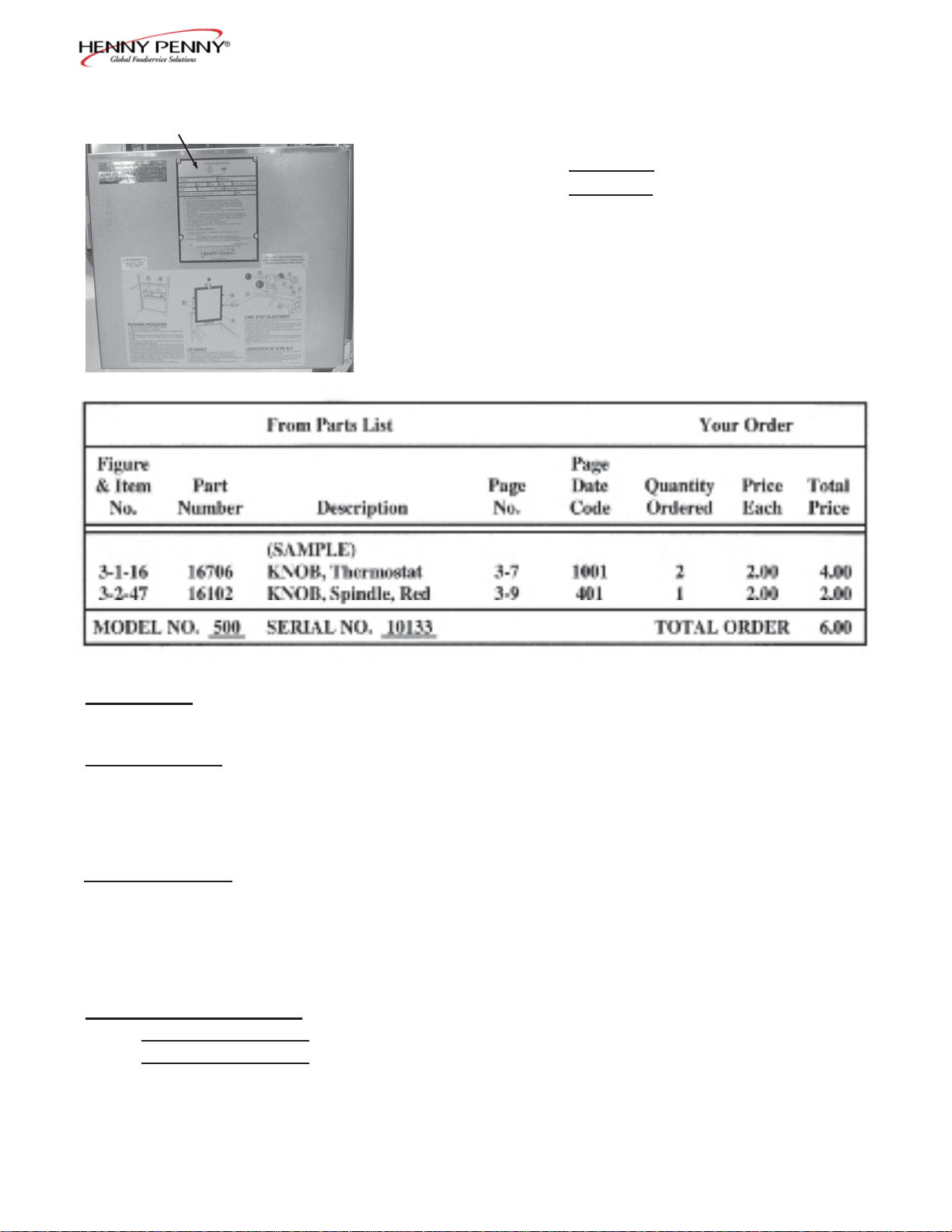
DATA PLATE
2. From the data plate on your unit: (SAMPLE)
Model number 500
Serial number 10133
3. The following table has been provided as a sample format
you to use in preparing your spare parts orders. By
providing all the entries, your distributor will be able to
send you the correct parts. Also, prepayment expedites
your order.
3-7. PRICES
Your distributor has a priced parts list and will be glad to inform
you of the cost of your parts order.
3-8. DELIVERY
Commonly replaced items are stocked by your distributor and areshipped when your order is received. Other parts are ordered, by
your distributor, from Henny Penny Corporation. Normally, these
are sent to your distributor within 3 working days.
3-9. WARRANTY
All replacement parts (except lamps and fuses) are warranted
for 90 days against manufacturing defects and workmanship. If
damage occurs during shipping, notify the sender and the carrier
at once, so that a claim is properly fi led. Refer to warranty in the
front of this manual for other rights and limitations.
3-10. RECOMMENDED
SPARE PARTS FOR
DISTRIBUTORS
Recommended replacement parts, stocked by your distributor, are
indicated with in the parts lists. Please use care when ordering recommended parts, because all voltages and variations are
marked. Distributors should order parts based upon common
voltages and equipment sold in their territory.
206 3-3
Page 4

Model 500/600
3-11. INDEX OF PARTS LIST ILLUSTRATIONS
Title Fig. No. Page No.
CONTROL SHROUD and COMPONENTS ................................................ 3-17 3-38
(Electric Model) Single Phase
CONTROL SHROUD and COMPONENTS ................................................ 3-16 3-36
(Three Phase Electric Model)
CONTROL PANEL ....................................................................................... 3-1 3-6
COUNTERTOP INSULATION ASSEMBLY (Gas Model) .......................... 3-10 3-24
DEADWEIGHT VALVE ASSEMBLY .......................................................... 3-3 3-9
DRAIN VALVE ASSEMBLY (Electric Model) ............................................ 3-7 3-18
DRAIN VALVE ASSEMBLY (Gas Model) .................................................. 3-6 3-16
ELECTRIC CONDUIT ASSEMBLY ............................................................ 3-23 3-54
ELECTRONIC IGNITION ASSEMBLY ...................................................... 3-24 3-56
EXHAUST STACK ASSEMBLY .................................................................. 3-4 3-11
FAN and HIGH TEMPERATURE LIMIT CONTROL (Gas Model) ........... 3-8 3-20
FILTER DRAIN PAN and FILTER SCREEN ASSEMBLY ......................... 3-19 3-43
FILTER MOTOR and PUMP ........................................................................ 3-21 3-49
FIREBOX and FLUE ASSEMBLY (Gas Model) .......................................... 3-11 3-26
FIREBOX INSULATION ASSEMBLY (Gas Model) ................................... 3-12 3-28
FRAME and CABINET ASSEMBLY ........................................................... 3-18 3-40
3-4 305
Page 5

Model 500/600
3-11. INDEX OF PARTS LIST ILLUSTRATIONS (continued)
Title Fig. No. Page No.
FRY BASKET ................................................................................................ 3-9 3-22
FRYPOT and GAS BURNER ASSEMBLY (Gas Model) ............................. 3-14 3-32
GAS CONTROL VALVE .............................................................................. 3-13 3-30
HEATING ELEMENT and HIGH LIMIT ASSEMBLY (Electric Model) .... 3-15 3-34
LID ASSEMBLY .......................................................................................... 3-2 3-7
LOWER FILTER PLUMBING COMPONENTS ......................................... 3-20 3-46
SOLENOID VALVE ASSEMBLY ................................................................ 3-5 3-14
UPPER FILTER PLUMBING COMPONENTS ........................................... 3-22 3-51
305 3-5
Page 6
Model 500/600
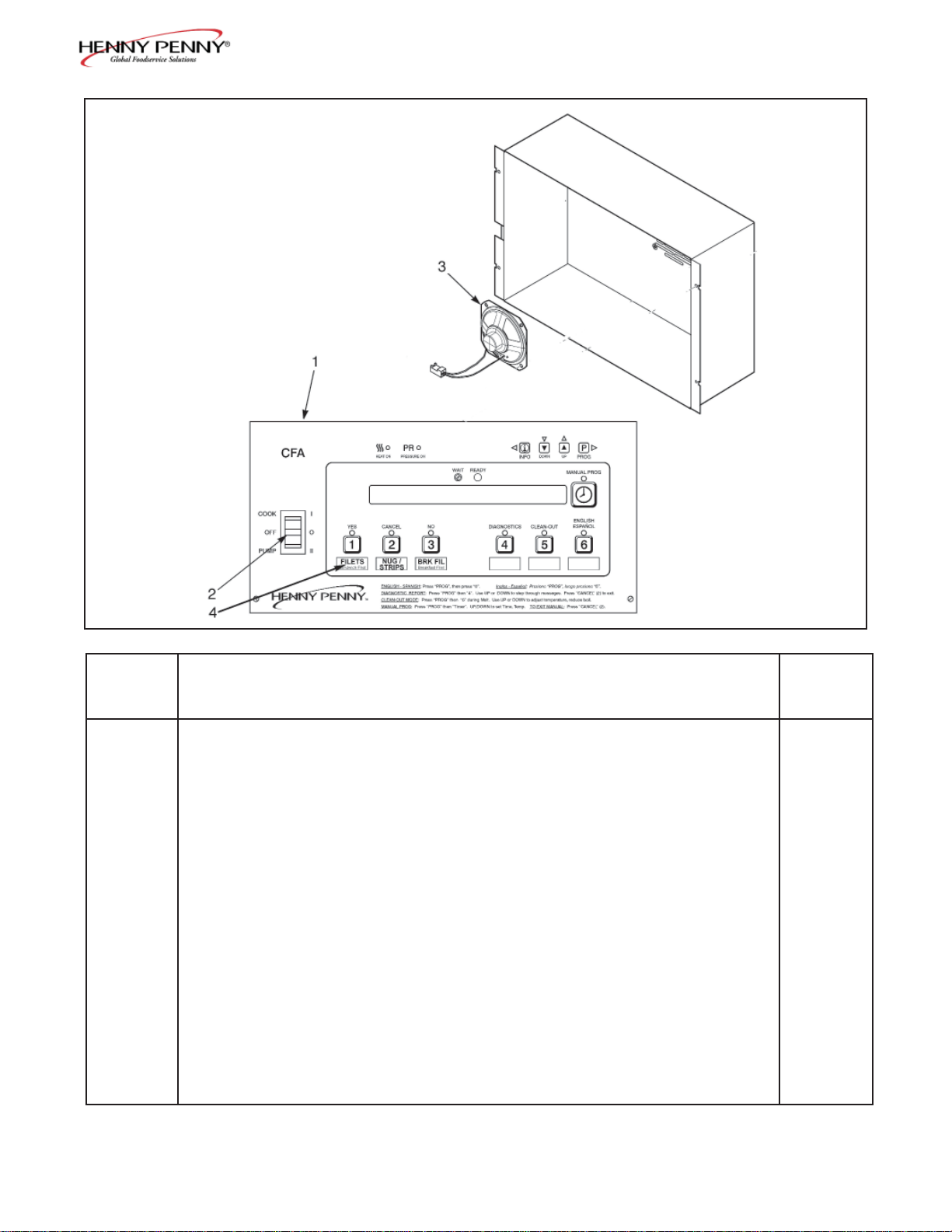
Figure 3-1. Control Panel
FIGURE UNITS
& ITEM PART PER
NO. NUMBER DESCRIPTION ASSY
3-1
67543RB CONTROL PANEL COMPLETE - Bent Panel 1
500 - SN: KB020JJ & Below/600 - SN: KA020JJ & Below
67544RB CONTROL PANEL COMPLETE - Flat Panel 1
500 - SN: KB021JJ to HB013JB/600 - KA021JJ to GA085JB
67830RB CONTROL PANEL COMPLETE - Flat Panel 1
500 - SN: HB014JB & Above/600 - SN: GA086JB & Above
1 61576 DECAL, CFA - Bent Panel 1
-SN: 500-KB020JJ & Below/600-SN: KA020JJ & Below
1 24281 DECAL, CFA - Flat Panel 1
-SN: 500-KB021JJ to HB013JB/600-KA021JJ to GA085JB
1 32669 DECAL, CFA - Flat Panel ‘02 1
-SN: 500-HB014JB & Above/600-GA086JB & Above
2 29898 COOK/PUMP SWITCH 1
3 26974 SPEAKER ASSEMBLY 1
4 61725 MENU CARD - CFA COMPUTRON 1
5* ME90-011 RELAY, 24VAC COIL (DPST) 1
6* 53669 GUARD, POWER SWITCH 1
Recommended Parts/* not shown
3-6 710
Page 7
Model 500/600
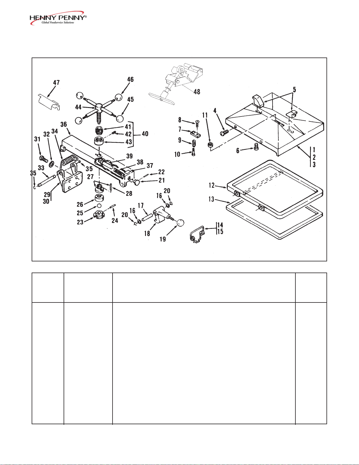
Figure 3-2. Lid Assembly
FIGURE UNITS
& ITEM PART PER
NO. NUMBER DESCRIPTION ASSY
3-2 LID ASSEMBLY
1 16170 LID ASSEMBLY .................................................................. 1
2 16169 COVER ASSEMBLY ...................................................... 1
3 16155 COVER, Lid ............................................................. 1
4 SC01-083 SCREW, Lid Cover ................................................... 4
5 16133 HOOK, Cover Retaining. .......................................... 2
6 SC06-027 SCREW, Retaining Hook .......................................... 4
7 16166 RETAINER ............................................................... 1
8 SC06-010 SCREW, Retaining Hook (Allen Head) .................... 1
9 16165 SPRING, Return ....................................................... 1
10 16164 PIN, Locking ............................................................. 1
11 16163 BALL, Seat ............................................................... 1
305 3-7
Page 8
Model 500/600
FIGURE UNITS
& ITEM PART PER
NO. NUMBER DESCRIPTION ASSY
3-2 Cont’d.
12 16119 LINER, Inner Lid ......................................................... 1
13 16120 GASKET, Reversible, Inner Lid Liner. ....................... 1
14 16199 KIT, Latch Spring .............................................................. 1
15 33480 SPRING ....................................................................... 1
16 16198 SPACER ....................................................................... 2
17 16197 PIN, Latch .................................................................... 1
18 16116 LATCH, Lid ....................................................................... 1
19 16102 KNOB, Latch ..................................................................... 1
20 16121 RING, Tru-Arc Latch ......................................................... 2
21 16137 KNOB, Retaining Pin ........................................................ 1
22 16138 PIN, Knob Roll ................................................................. 1
23 16157 COLLAR, Locking ............................................................ 1
24 16158 PIN, Locking Collar ........................................................... 1
25 16159 BALL, Thrust ..................................................................... 1
26 27326 NUT, Idle ........................................................................... 1
27 27329 NUT, Acme ........................................................................ 1
28 16162 PIN, Acme Nut ............................................................ 2
29 16112 HINGE, Lid Assembly ....................................................... 1
30 40235 HINGE, Lid ................................................................. 1
31 SC01-081 SCREW, Lid Hinge ...................................................... 4
32 LW01-010 WASHER, Lock, Lid Hinge ........................................ 4
33 16110 PIN, Lid Hinge ............................................................. 1
34 16108 HINGE, Lid Spring ............................................................ 1
35 16111 RING, Retainer, Tru-Arc, Hinge ........................................ 2
36 16154 BAR, Center Cross ............................................................ 1
37 36099 DECAL, DANGER ............................................................ 1
38 16136 SPRING, Retaining Pin ..................................................... 1
39 16135 COVER, Retaining Pin ...................................................... 1
40 16171 STOP, Limit Assembly ....................................................... 1
41 16153 STOP, Limit ................................................................. 1
42 16156 SCREW, Set, Limit Stop Collar ................................... 2
43 16152 COLLAR, Limit Stop .................................................. 2
44 16168 SPINDLE ASSEMBLY...................................................... 1
45 16102 KNOB, Spindle, Red.......................................................... 1
46 16101 KNOB, Spindle, Black ....................................................... 3
47 29587 COVER, Spring ................................................................ 1
48 14960 KIT, Spring Loading Tool .................................................. 1
Recommended Parts
3-8 206
Page 9
Model 500/600
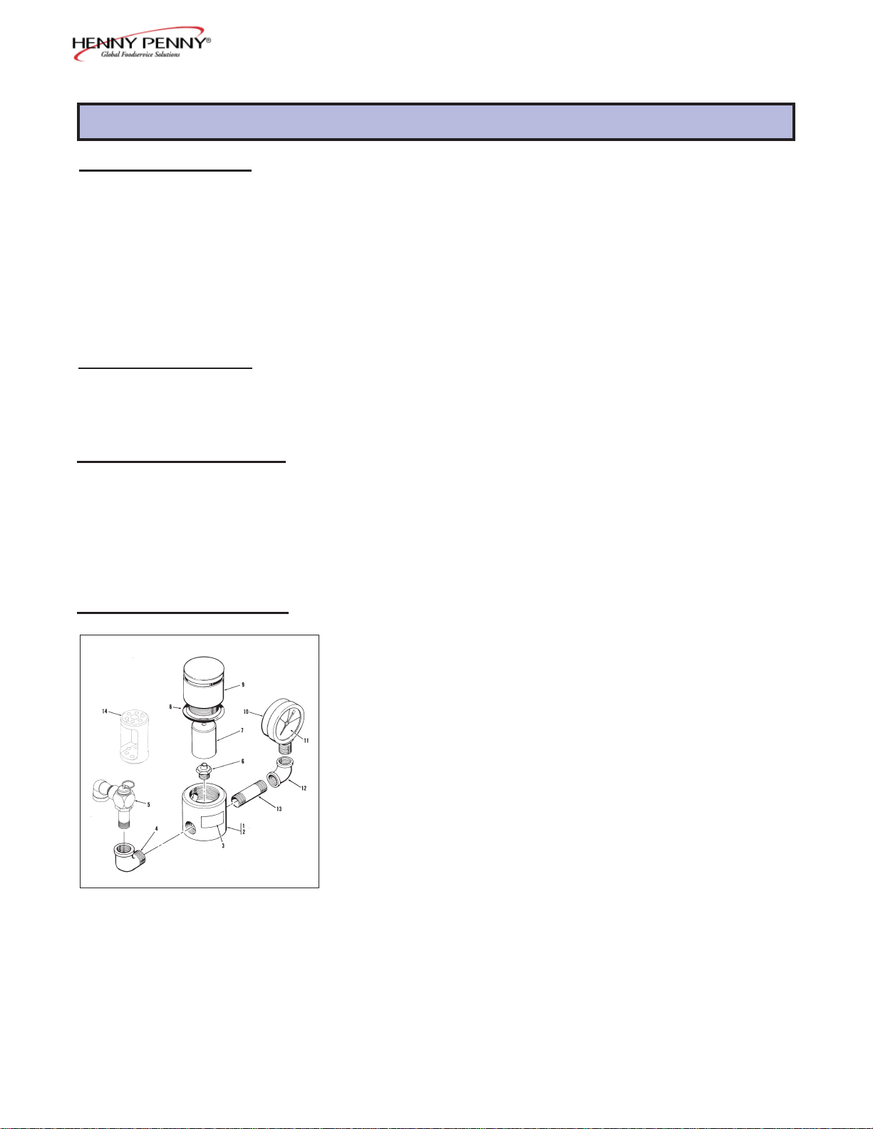
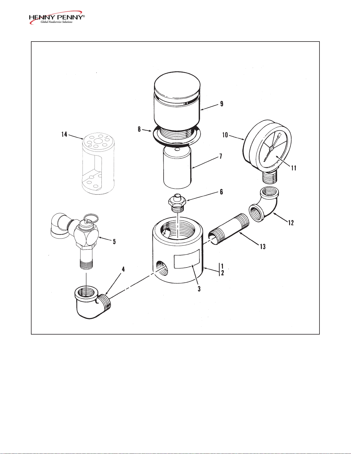
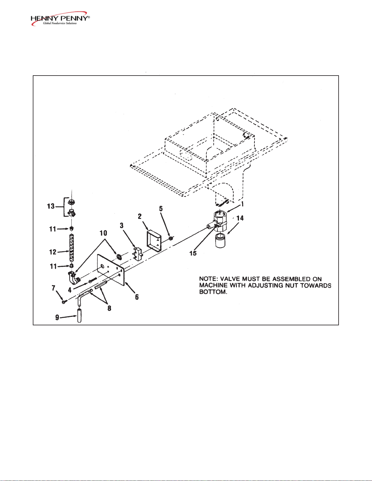
NOTE: Turn safety relief valve towards
rear of fryer.
Figure 3-3. Deadweight Valve Assembly
305 3-9
Page 10
Model 500/600
FIGURE UNITS
& ITEM PART PER
NO. NUMBER DESCRIPTION ASSY
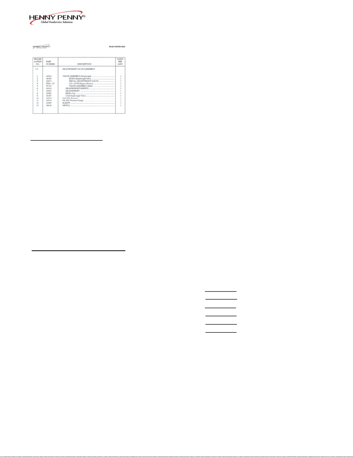
3-3 DEADWEIGHT VALVE ASSEMBLY
1 16924 VALVE ASSEMBLY, Deadweight ....................................... 1
2 56305 BODY, Deadweight Valve ............................................... 1
3 16912 DECAL, DEADWEIGHT VALVE ................................. 1
4 FP01-127 1/2 x 1/2 90 Degree Street L............................................ 1
5 59742 VALVE ASSEMBLY, Relief ........................................... 1
6 16918 DEADWEIGHT ORIFICE .............................................. 1
7 16903 DEADWEIGHT .............................................................. 1
8 16902 RING, Cap ....................................................................... 1
9 56307 CAP, Deadweight Valve .................................................. 1
10 16910 GAUGE, Pressure ................................................................. 1
11 16914 GLASS, Pressure Gauge ....................................................... 1
12 16909 ELBOW ................................................................................ 1
13 56636 NIPPLE ................................................................................. 1
Recommended Parts
3-10 206
Page 11
Model 500/600
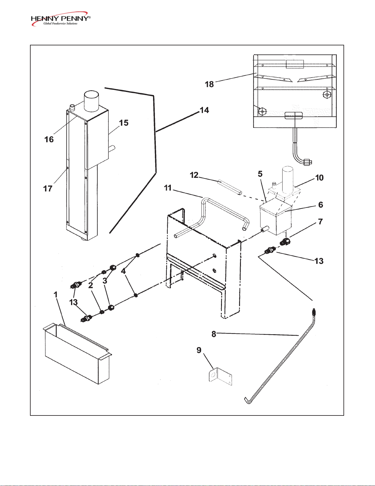
Figure 3-4. Exhaust Stack Assembly
906 3-11
Page 12
Model 500/600
FIGURE UNITS
& ITEM PART PER
NO. NUMBER DESCRIPTION ASSY
3-4 EXHAUST STACK ASSEMBLY
1 68086 PAN, Condensation Drain ..................................................... 1
1 64274 PAN, Condensation Drain - Short (CFA-SN: JB095JA to
HB013JB) ......................................................................... 1
2 16817 FITTING, Tefl on Sleeve ....................................................... 2
3 16809 NUT, Fitting .......................................................................... 2
4 16804 UMBRELLA GROMMET ................................................... 2
5 58852 CONDENSATE BOX - Bottom-See chart on next page .... 1
6 SC02-016 SCREW, #8-32-AB x 1/2 PH PHD S .................................. 4
7 FP01-122 REDUCER, 3/8 to 1/2 BI...................................................... 1
8 TUBE, Condensation Assembly-See chart on next page .... 1
9 63992 BRACKET, Condensation Hose ........................................... 1
10 64013 CONDENSATE BOX - Top-See chart on next page .......... 1
11 TUBE, Deadweight-See chart on next page ....................... 1
12 HOSE, Deadweight to Steam Box-See chart on next page 1
13 16807 CONNECTOR, Male ............................................................ 3
14 65724 ASSY, Condensate Box-See chart on next page ................. 1
15 65725 WELD ASSY, Steam Box - Outer ................................... 1
16 65726 WELD ASSY, Steam Box - Inner ................................... 1
17 SC04-003 SCREW, #8-32 x 3/8 PH PHD S ..................................... 6
18 21302 ASSY, Exhaust Stack - 500 - SN: KB020JJ & Below .......... 1
3-12 906
Page 13
Model 500/600
Exhaust Stack Assembly
SN 500 600
KB020JJ & Condensation Line Assy 18502 Below
KA020JJ & Condensation Line Assy - 16838
Below Dead Wt. Tube - 16854
KB021JJ to Condensation Line Assy 14320 BB016JA Condensate Box Top 64013 -
Dead Wt. Tube 59221 -
DW To Steam Box Hose 63195 -
Condensate Box 58852 KA021JJ to Condensation Line Assy - 14320
BA026JA Condensate Box Top - 64013
Dead Wt. Tube - 59221
DW To Steam Box Hose - 63195
Condensate Box - 58852
BB017JA to Condensation Line Assy 64016 EB015JB Condensate Box Top 64013 -
Dead Wt. Tube 59221 -
DW To Steam Box Hose 63195 -
Condensate Box 58852 BA027JA to Condensation Line Assy - 64016
EA014JB Condensate Box Top - 64013
Dead Wt. Tube - 59221
DW To Steam Box Hose - 63195
Condensate Box - 58852
EB016JB to Condensation Line Assy 24998 HB013JB Condensate Box Top
(except Dead Wt. Tube 65621 -
use 65724 -
EB018JB & DW To Steam Box Hose 26866 EB019JB) Condensate Box Bottom
Condensate Box
EA015JB to
Condensation Line Assy - 24998
GA085JB Condensate Box Top -
Dead Wt. Tube
DW To Steam Box Hose -
Condensate Box Bottom -
use 65724 -
use 65724 -
use 65724
- 65621
26866
use 65724
Condensate Box - use 65724
HB014JB &
Above Dead Wt. Tube
GA086JB &
Condensation Line Assy 69009
65621
DW To Steam Box Hose
Condensate Box
26866
65724
Condensation Line Assy
Above Dead Wt. Tube -
DW To Steam Box Hose -
Condensate Box -
-
-
-
-
-
69009
65621
26866
65724
906 3-13
Page 14
Model 500/600
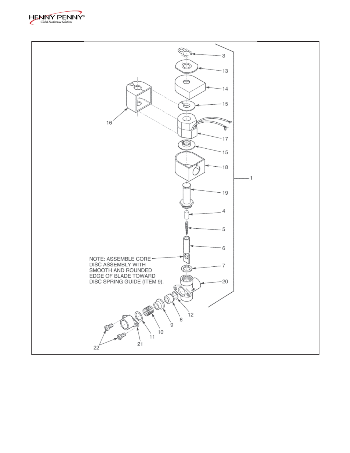
Figure 3-5. Solenoid Valve Assembly
3-14 1005
Page 15
Model 500/600
FIGURE UNITS
& ITEM PART PER
NO. NUMBER DESCRIPTION ASSY
.
3-5 SOLENOID VALVE ASSEMBLY
(Gas and Electric Models)
1 17121 VALVE, Solenoid, 120 Volt, 60 Hz ....................................... 1
1 18724 VALVE, Solenoid, 208-240 Volt, 50 Hz .............................. 1
1 18721 VALVE, Solenoid, 208/240 Volt, 60 Hz .............................. 1
1 29515 VALVE, Solenoid, 24 Volt, 60 Hz ......................................... 1
1 29698 VALVE, Solenoid, 24 Volt, 50 Hz ......................................... 1
2* 17120 KIT, Solenoid Valve Repair ................................................. 1
3 17101 CLIP, Retaining ........................................................ 1
4 17109 RETAINER, Spring .................................................. 1
5 17110 SPRING, Core ........................................................... 1
6 17111 CORE, Disc Assembly .............................................. 1
7 17112 GASKET, Bonnet ...................................................... 1
8 17114 SEAT, Tefl on ............................................................. 1
9 17115 GUIDE, Disc Spring .................................................. 1
10 17116 SPRING, Disc ........................................................... 1
11 17117 RING, Spring Retainer ............................................... 1
12 17122 SEAT, O-Ring Seal .................................................... 1
13 17102 PLATE, Solenoid Name ................................................... 1
14 17103 COVER, Coil Housing ..................................................... 1
15 17104 WASHER, Coil ................................................................ 2
16 17105 YOKE, Coil ...................................................................... 1
17 17106 COIL, 120 Volt, 60 Hz ..................................................... 1
17 18706 COIL, 208/240 Volt, 60 Hz .............................................. 1
17 18726 COIL, 208-240 Volt, 50 Hz .............................................. 1
17 29547 COIL, 24 Volt, 60 Hz ....................................................... 1
17 29575 COIL, 24 Volt, 50 Hz ....................................................... 1
18 17123 HOUSING, Coil ............................................................... 1
19 17108 BONNET, Solenoid .......................................................... 1
20 17113 BODY, Solenoid Valve ..................................................... 1
21 17118 ADAPTER, Pipe .............................................................. 1
22 SC01-132 SCREW, Adapter .............................................................. 2
Recommended Parts
*not shown
206 3-15
Page 16
Model 500/600
Figure 3-6. Drain Valve Assembly (Gas Model)
3-16 305
Page 17

Model 500/600
FIGURE UNITS
& ITEM PART PER
NO. NUMBER DESCRIPTION ASSY
3-6 DRAIN VALVE ASSEMBLY
(Gas Model)
1 17261 BODY, Drain Valve (June 1998 and above) .............. 1
2 17210 COVER, Microswitch .............................................. 1
1 55152 ASSY, Drain Valve and Coupling
(May 1998 and below) 1
3 18227 MICROSWITCH ..................................................... 1
4 SC01-058 SCREW, Microswitch .............................................. 2
5 NS02-005 NUT, Microswitch ................................................... 2
6 l72l1 BRACKET, Drain, Valve Rod ................................. 1
7 SC03-005 SCREW, Drain Bracket ............................................ 2
8 17254 ROD, Drain Valve - Normally Closed ...................... 1
8 67661 ROD, Drain Valve - Normally Open ......................... 1
9 16293 COVER, Valve Handle ............................................ 1
10 18644 CONNECTOR, 90° Flexible Conduit ...................... 1
(Includes Nut)
11 18105 INSULATOR ........................................................... 2
12 17214 CONDUIT, Flexible .................................................. 1
13 18111 CONNECTOR, Flexible Conduit (Includes Nut) ..... 1
14 18819 EXTENSION NIPPLE (SN: KA020JJ and below) ... 1
14 18817 EXTENSION NIPPLE (SN: KA021JJ to GA085JB) 1
14 24647 EXTENSION & DEFLECTOR ................................. 1
(SN: GA086JB and above)
15 17255 PIN, Cotter ................................................................. 2
16* 14652 KIT, PFG600 Norm Open Drain Switch .................... 1
Recommended Parts
*not shown
206 3-17
Page 18

Model 500/600
Figure 3-7. Drain Valve Assembly (Electric Model)
3-18 305
Page 19

Model 500/600
FIGURE UNITS
& ITEM PART PER
NO. NUMBER DESCRIPTION ASSY
3-7 DRAIN VALVE ASSEMBLY
(Electric Model)
1 18921 TOP ASSEMBLY, Pot and Counter-SN: KB020JJ & Below 1
1 65025 TOP ASSEMBLY, Pot and Counter-KB021JJ & Above ...... 1
2 18816 NIPPLE, Pipe ...................................................................... 1
3 16239 ELBOW ............................................................................... 1
4 18816 NIPPLE, Pipe ...................................................................... 1
7 18817 NIPPLE, Drain Extension-SN: KB020JJ & Below .............. 1
7 58851 NIPPLE, Drain Extension-SN: KB021JJ to HB013JB ........ 1
7 24633 NIPPLE, Drain Extension & Defl ector
-SN: HB014JB & Above 1
8 17261 BODY, Drain Valve (SN: FB099IH and above) ................... 1
8 55152 ASSY, Drain Valve and Coupling (SN: FB098IH and below) 1
9 18818 ROD, Drain Valve Extension - Normally Closed ................. 1
9 66123 ROD, Drain Valve Extension - Normally Open ................... 1
10 16293 COVER, Valve Handle ........................................................ 1
11 18419 BRACKET, Filter & Drain Rod-SN: KB020JJ & Below ... 1
11 59219 BRACKET, Filter & Drain Rod-SN: KB021JJ to HB013JB 1
11 27412 BRACKET, Filter & Drain Rod-SN: HB014JB & Above .. 1
12 SC03-005 SCREW, Drain Valve Bracket ............................................. 2
13 18227 MICROSWITCH ................................................................. 1
14 SC01-058 SCREW, Microswitch .......................................................... 2
15 NS02-005 NUT, Microswitch ............................................................... 2
16 18528 COVER, Microswitch ......................................................... 1
17 EF02-004 BUSHING, Snap .................................................................. 1
18 17255 PIN, Cotter ............................................................................ 2
19* 14653 KIT, PFE500 Norm Open Drain Switch ............................... 1
Recommended Parts
*not shown
206 3-19
Page 20

Model 500/600
9
Figure 3-8. Fan and High Temperature Limit Control (Gas Model)
3-20 305
Page 21

Model 500/600
FIGURE UNITS
& ITEM PART PER
NO. NUMBER DESCRIPTION ASSY
3-8 FAN AND HIGH TEMPERATURE LIMIT
CONTROL (Gas Model)
1 16738 CONTROL, High Temperature Limit ....................................... 1
2 SC02-018 SCREW, Thread Forming #8 .................................................... 2
3 NS02-001 NUT, #10-32 Hex Keps ............................................................ 2
4 17216 BRACKET ASSY, High Limit Thermostat .............................. 1
5 81208 FAN, 120 Volt ........................................................................... 1
6 SC01-266 SCREW, Fan ............................................................................. 4
7 WA01-006 WASHER, Fan .......................................................................... 4
8 NS02-005 NUT, Fan ................................................................................... 4
9 72854 ASSY, TRANSFORMER - 24 VAC ......................................... 1
10 14331 KIT, Temperature Probe ............................................................ 1
11* 36097 PROBE GUARD ..................................................................... 1
Recommended Parts
*not shown
206 3-21
Page 22

Model 500/600
Figure 3-9. Fry Basket
3-22 305
Page 23

Model 500/600
FIGURE UNITS
& ITEM PART PER
NO. NUMBER DESCRIPTION ASSY
3-9 FRY BASKET (Gas and Electric Models)
1 17801 BASKET, Without Legs, Gas Model Only ........................ 1
1 64058 BASKET, 3 Layer - Gas Model Only ................................ 1
1 19507 BASKET, Expanded Metal - Electric Model Only ............. 1
2 19502 HANDLE ............................................................................ 1
3* 29769 GRIP, Fryer Handle ............................................................. 1
*not shown
305 3-23
Page 24

Model 500/600
13
12
Figure 3-10. Countertop Insulation Assembly (Gas Model)
3-24 305
Page 25

Model 500/600
FIGURE UNITS
& ITEM PART PER
NO. NUMBER DESCRIPTION ASSY
3-10 COUNTERTOP INSULATION ASSEMBLY . ...................
(Gas Model)
1 14698 KIT, Complete Set - SN: KA020JJ & Above......................... 1
1 16518 INSULATION, Complete Set-SN: 36886 to KA020JJ .......... 1
(Includes Part Nos. 16505,17605,16872,
MS01-180, Bulk Cerefelt Insulation For
Around Thermocouple, Pot Fittings, and Glue.)
2 63301 INSULATION, Fiberglass .................................................... 1
3 63302 INSULATION, Cerefelt - Flue Top ..................................... 1
4 16308 BOARD, Aircell ................................................................... 1
5 53807 INSULATION, Countertop-sides .......................................... 2
6 16303 INSULATION, Fiberglass ................................................... 1
7 63699 INSULATION, Fiberglass Notched ..................................... 2
8 63623 INSULATION, Heat Shield, Inner ......................................... 1
9 59232 HEAT SHIELD ...................................................................... 1
12 59965 INSULATION, Countertop Side ............................................ 2
13 59966 INSULATION, Countertop Front .......................................... 1
14 53808 INSULATION, Countertop-Front/Rear ................................. 2
505 3-25
Page 26

Model 500/600
1
Figure 3-11. Firebox and Flue Assembly (Gas Model)
3-26 305
Page 27

Model 500/600
FIGURE UNITS
& ITEM PART PER
NO. NUMBER DESCRIPTION ASSY
3-11 FIREBOX AND FLUE ASSEMBLY ..................................
(Gas Model)
1 59728 STACK, Flue Exhaust - SN: KA021JJ & Above ................... 1
1 54865 STACK, Flue Exhaust - SN: KA020JJ & Below ................... 1
2 59223 CABINET ASSEMBLY, Firebox - SN: KA021JJ & Above 1
2 29679 CABINET ASSEMBLY, Firebox - SN: KA020JJ & Below 1
3 18625 BRACKET, Side Panel Insulation ........................................ 2
4 87448 PANEL, Firebox Front .......................................................... 1
5 16406 DEFLECTOR, Heat Shield .................................................. 1
6 SC03-005 SCREW, Sheet Metal ........................................................... 20
7 18626 BRACKET, Side Panel Insulation, Rear ............................... 2
* not shown
710 3-27
Page 28

Model 500/600
Figure 3-12. Firebox Insulation Assembly (Gas Model)
3-28 305
Page 29

Model 500/600
FIGURE UNITS
& ITEM PART PER
NO. NUMBER DESCRIPTION ASSY
3-12 FIREBOX INSULATION ASSEMBLY ..............................
(Gas Model)
1 16505 INSULATION, Firebox - Complete Set ................................ 1
Cerefelt, Inside Firebox
2 63111 INSULATION, Side Panel , Cerefelt ............................ 2
3 16502 INSULATION, Back Panel, Cerefelt .............................. 1
4 16503 INSULATION, Bottom Panel, Cerefelt .......................... 1
5 29690 INSULATION, Front Panel, Cerefelt ............................ 1
305 3-29
Page 30

Model 500/600
Style 1
1 1 1
Style 2 Style 3 Style 4
Figure 3-13. Gas Control Valve
3-30 710
Page 31

Model 500/600
FIGURE UNITS
& ITEM PART PER
NO. NO. DESCRIPTION ASSY
3-13 GAS CONTROL VALVE
1 ------- VALVE, Gas Control
-- See Table 1 Below .................................... 1
2 16254 OPERATOR, Gas Control Valve, 120 Volt, Natural ...................... 1
2 16386 OPERATOR, Gas Control Valve, 120 Volt, Propane ..................... 1
3 16253 REGULATOR, Gas Control Valve, Natural Gas ........................... 1
4 16352 REGULATOR, Gas Control Valve, Propane Gas .......................... 1
6 16267 KNOB, Gas Control Valve ............................................................ 1
7 16373 FITTING, Compression - Pilot Tube ............................................. 2
8* 16247 KIT, Nat. to LP Conversion - KA020JJ & Below .......................... 1
8* 16248 KIT, LP to Nat. Conversion - KA020JJ & Below .......................... 1
8* 14324 KIT, Nat. to LP Conversion - KA021JJ to July 10, 2006 ................ 1
8* 14325 KIT, LP to Nat. Conversion - KA021JJ to July 10, 2006 ................ 1
8* 14723 KIT, Solid State Ign.-Nat. to LP Conversion -July 10, 2006 & after ...... 1
8* 14724 KIT, Solid State Ign.-LP to Nat. Conversion -July 10, 2006 & after ..... 1
Recommended Parts
* not shown
TABLE 1
Voltage Nat. Electronic Ign. LP Electronic Ign. Nat. Std. Ign. LP Std. Ign. Town Gas
†34439
120V
240V
24V
24V
24V/50Hz
240V/50Hz
† - Style 1, Integral lead wires ‡ - Style 2, 3 screw terminals
# - Style 3, 2 screw terminals and/or cover ◊ - Style 4, 3 spade terminals and ON/OFF switch
NOTE: Part # 16216 and 16380 consist of items 2 and 3 and part # 16217 and 16381 consist of items 2 and 4.
710 3-31
(SN: KA020JJ
and Below)
-------- †21316 †16380 †16381 †16262
◊140043
(SN: KA021JJ to
AN0901028)
◊80761
(SN: AN0901029
and Above)
-------- -------- #34806 #34805 --------
-------- -------- #34804 #34803 --------
-------- †16216 †16217
◊21332
(SN: KA021JJ to
AN0901028)
◊80858
(SN: AN0901029
And Above)
#29614
(SN: KA020JJ
and Below)
‡58863
(SN: KA021JJ
and Above)
#29728
(SN: KA020JJ
and Below)
‡64036
(SN: KA021JJ
and Above)
Use †16262
and 16254
--------
--------
Page 32

Model 500/600
29
Figure 3-14. Frypot and Gas Burner Assembly
3-32 305
Page 33

Model 500/600
FIGURE UNITS
& ITEM PART PER
NO. NUMBER DESCRIPTION ASSY
3-14 FRYPOT AND GAS BURNER ASSEMBLY
1 16889 TOP ASSEMBLY, Pot and Counter (SN: KA020JJ & below) ... 1
1 65007 TOP ASSEMBLY, Pot and Counter (SN: KA021JJ & above) ... 1
2 18816 NIPPLE, Pipe S.S ....................................................................... 2
3 53834 J-BOLT, Burner Hold Down ....................................................... 1
4 16205 CASTING Burner ....................................................................... 1
5 17013-1 SET, Orifi ce, Natural Gas ........................................................... 1
5 16561-1 ORIFICE, Natural Gas, S.S ................................................ 1
5 16562-1 ORIFICE, Natural Gas, Brass ............................................ 23
5 17013-3 SET, Orifi ce, Propane Gas .......................................................... 1
5 16561-3 ORIFICE, Propane Gas, S.S ............................................... 1
5 16562-3 ORIFICE, Propane Gas, Brass ........................................... 23
6 FP01-020 PLUG, Burner Casting................................................................ 3
7 29969 BRACKET, Pilot Holder ............................................................ 1
8 SC01-184 SCREW, Pilot Holder Bracket .................................................... 2
9 Use #11 PILOT & ORIFICE ASSEMBLY ............................................... 1
10 SC01-047 SCREW, Pilot Holder ................................................................. 1
11 30904 PILOT & BRACKET ASSEMBLY, LP ...................................... 1
11 30913 PILOT & BRACKET ASSEMBLY, Nat .................................... 1
12 16336 ELBOW, Male ............................................................................ 1
13 SC06-013 BOLT, U, Gas Line ..................................................................... 2
14 NS02-002 NUT, Gas Supply Line Bolt ........................................................ 4
15 16333 LINE, Gas Burner to Control...................................................... 1
16 16335 NIPPLE, Close ............................................................................ 3
17 29820 ORIFICE, Pilot, Natural Gas ...................................................... 1
17 32407 ORIFICE, Pilot, Propane Gas ..................................................... 1
18 63198 PILOT ASSEMBLY, Gas Tube ................................................... 1
19 16219 THERMOCOUPLE .................................................................... 1
20 ------- VALVE, Gas Control - 24V -- See Figure 3-13 ........................ 1
21 16221 SPACER, Heat Shield ................................................................. 2
22 SC01-054 SCREW, Heat Shield .................................................................. 2
23 58866 SHIELD, Heat, Aluminum ......................................................... 1
24 SC02-006 SCREW, Bracket ........................................................................ 4
25 40304 LINE, Gas Supply (SN: KA020JJ & below) .............................. 1
25 16326 LINE, Gas Supply ....................................................................... 1
26 16331 GAS LINE BRACKET ............................................................... 1
27 FP01-007 COUPLING, Pipe ...................................................................... 1
28 16328 BRACKET, Gas Line ................................................................. 1
- 16329 Nut 37 Flare for 5/8 OD.............................................................. 2
- 16330 Sleeve 37 Flare for 5/8 ................................................................ 2
29 24687 GUARD, Gas Valve Adjustment Screw ..................................... 1
30* 14484 KIT, 3/4 in. x 5 ft. Gas Line w/quick-disconnect ....................... 1
Recommended Parts
* not shown
710 3-33
Page 34

Model 500/600
Figure 3-15. Heating Element and High Limit Assembly (Electric Model)
3-34 505
Page 35

Model 500/600
FIGURE UNITS
& ITEM PART PER
NO. NUMBER DESCRIPTION ASSY
3-15 HEATING ELEMENT AND HIGH LIMIT
ASSEMBLY, (Electric Models)
1 18233-1 ELEMENT COMPLETE, Heating ................................... 3
208 Volts, 4500 Watts
1 18233-2 ELEMENT COMPLETE, Heating ................................... 3
230 Volts, 4500 Watts
1 18233-5 ELEMENT COMPLETE, Heating ................................... 3
230 Volts, 3750 Watts
1 18233-4 ELEMENT COMPLETE, Heating ................................... 3
208 Volts, 3750 Watts
1 18233-6 ELEMENT COMPLETE, Heating ................................... 3
480 Volts, 3750 Watts
1 18233-7 ELEMENT COMPLETE, Heating ................................... 3
480 Volts, 4500 Watts
2 16855 SEAL O-RING .................................................................. 6
3 WA01-005 WASHER, Heating Element, Metal .................................. 6
4 NS01-017 NUT, Heating Element, Brass ........................................... 6
5 NS01-014 NUT, Heating Element ...................................................... 12
6 WA01-007 WASHER, Heating Element ............................................. 12
7 LW01-008 WASHER, Lock, Heating Element ................................... 6
8 18720 CLAMP, Rear-Hi Limit..................................................... 2
9 18248 CLAMP, Front-Hi Limit ................................................... 2
10 14685 KIT, Spreader Module....................................................... 5
11 18225 SPREADER, Element ................................................ 5
12 18226 BAR, Spreader Lock ................................................... 5
13 SC01-055 SCREW, Element Spreader (including Firebars) ....... 10
14 LW02-005 WASHER, Lock, Element Spreader ........................... 10
15 SC01-053 SCREW, 8-32 x 1/2 PH RD SS ......................................... 2
16 SC02-018 SCREW, Thread Forming #8 ............................................ 2
17 16738 CONTROL, Hi Limit Temperature ................................... 1
18 NS02-001 NUT, #10-32 Hex Keps .................................................... 2
19 17216 BRACKET ASS’Y, Hi Limit Thermostat ......................... 1
20 18211 HOLDER, Thermostat Bulb ............................................. 1
21 14785 ASSEMBLY, Probe/Compression Fitting ......................... 1
Recommended Parts
710 3-35
Page 36

Model 500/600
Figure 3-16. Control Shroud and Components (Three Phase Electric Model)
3-36 305
Page 37

Model 500/600
FIGURE UNITS
& ITEM PART PER
NO. NUMBER DESCRIPTION ASSY
3-16 CONTROL SHROUD AND COMPONENTS
(Three Phase Electric Model)
1 18514 SHROUD, Three Phase (KB020JJ & below) ............................... 1
1 59233 SHROUD, Three Phase (KB021JJ to HB013JB) ......................... 1
1 65864 SHROUD, Three Phase (HB014JB & above) ............................... 1
2 29509 CONTACTOR - 24 Volt ................................................................ 1
3 29510 CONTACTOR, Mercury - 24 VAC (Before SN: AA0909048) .... 1
3 65073 CONTACTOR, EM - 24VAC (SN: AA0909048 & Above) ......... 1
4 66717 STUD ASSY, Contactor Bracket ................................................... 1
5 FP01-024 BUSHING, Pipe - 1/8-3/8 ............................................................. 1
6 14785 ASSY, Probe/Compression Fitting ................................................ 1
7 16738 CONTROL, High Limit Temperature ........................................... 1
8 72854 ASSY, Transformer - 24 VAC ....................................................... 1
9 17216 ASSY, Bracket - High Limit ......................................................... 1
10 24347 ASSY, Current Sense Xformers .................................................... 1
11 18364 ASSY, Fuse Holder - 15 amp ........................................................ 2
11 EF02-007 FUSE, 15 amp ......................................................................... 2
11 EF02-006 HOLDER, Fuse ....................................................................... 2
12 58850 BRACKET, Double Contactor ...................................................... 1
13* 14034 KIT - 1 Phase to 3 Phase Conversion (KB020JJ & below) .......... 1
13* 14679 KIT - 1 Phase to 3 Phase Conversion (KB021JJ to HB013JB) .... 1
13* 14680 KIT - 1 Phase to 3 Phase Conversion (HB014JB & above) ......... 1
Recommended Parts
*not shown
710 3-37
Page 38

Model 500/600
Figure 3-17. Control Shroud and Components (Single Phase Electric Model)
3-38 305
Page 39

Model 500/600
FIGURE UNITS
& ITEM PART PER
NO. NUMBER DESCRIPTION ASSY
3-17 CONTROL SHROUD AND COMPONENTS,
(Electric Model) Single Phase
1 29510 CONTACTOR, Mercury-24 VAC (Before SN: AA0909048) ... 1
1 65073 CONTACTOR, EM-24VAC (SN: AA0909048 & Above) ......... 1
2 29509 CONTACTOR - 24 Volt ............................................................ 1
3 16738 CONTROL, High Limit Temperature ....................................... 1
4 NS01-014 NUT, Hex .................................................................................. 16
5 WA01-007 WASHER .................................................................................. 16
6 LW02-005 LOCKWASHER........................................................................ 8
7 18242 BREAKER, CIRCUIT 50 amp ................................................. 1
8 24347 ASSY, Current Sense Xformers ................................................ 1
9 72854 ASSY, Transformer - 24 VAC ................................................... 1
10 18364 ASSY, Fuse Holder - 15 amp .................................................... 2
10 EF02-007 FUSE, 15 amp ........................................................................... 2
10 EF02-006 HOLDER, Fuse ................................................................... 2
11 17216 ASSY, Bracket - High Limit ..................................................... 1
12 18244 SHROUD, Single Phase (KB020JJ & below) ........................... 1
12 63226 SHROUD, Single Phase (KB021JJ to HB013JB) ..................... 1
12 27418 SHROUD, Single Phase (HB014JB & above) .......................... 1
13 29687 BRACKET, Double Contactor .................................................. 1
14* 14033 KIT-3 Phase to 1 Phase Conversion (KB020JJ & below) ......... 1
14* 14677 KIT-3 Phase to 1 Phase Conversion (KB021JJ to HB013JB) ... 1
14* 14678 KIT-3 Phase to 1 Phase Conversion (HB014JB & above) ........ 1
Recommended Parts
*not shown
710 3-39
Page 40

Model 500/600
Figure 3-18. Frame and Cabinet Assembly
3-40 305
Page 41

Model 500/600
FIGURE UNITS
& ITEM PART DESCRIPTION PER
NO. NUMBER ASSY
3-18 FRAME AND CABINET ASSEMBLY
1 FRAME ASSEMBLY-See chart on next page ........... 1
2 COVER, Back Shroud-See chart on next page .......... 1
3 SC03-005 SCREW, Panels and Bracket, Sheet Metal ................... 22
4 SHROUD ASSEMBLY-See chart on next page ......... 1
5 59730 INSULATION, Side Panel, (Gas only) ........................ 2
6 PANEL, Right Side, SS
-See chart on next page ........... 1
7 54225 INSERT, Aluminum Feet - 1 in. x 1 in.......................... 4
7 17612 INSERT, Aluminum Feet - 1 in. x 1-1/2 in. .................. 4
8 59230 BRACKET, Magnetic Catch ......................................... 1
8 17002 MAGNET ..................................................................... 1
9 03007 CASTER, Assembly .................................................... 1
10 17630 CASTER, Less Brake ............................................. 2
11 17629 CASTER, w/Brake ................................................. 2
12 17639 DOOR ASSEMBLY, Complete (KB020JJ & below-ele) 1
(KA020JJ & below-gas)
12 58849 DOOR ASSEMBLY, Complete (KB021JJ & above-ele) 1
(KA021JJ & above-gas)
13 17620 HINGE, Bottom Door ............................................. 1
14 17618 HINGE, Top Door ................................................... 1
15 SC01-072 SCREW, Door Hinge .............................................. 8
16 41836 HANDLE, Door ...................................................... 1
17 PANEL, Front, Stainless Steel-See chart on next page 1
18 SC04-003 SCREW, Back Shroud .................................................. 6
19 PANEL, Side Left, SS-See chart on next page ........... 1
20 17627 LUG, Grounding ........................................................... 1
21 17611 SCREW, Grounding Lug .............................................. 1
22 SC01-143 5/8-18x4 Hex Hd (bright fi nish) (adjust. legs) .............. 4
22 SC01-067 5/8-18x3-1/4 Hex Hd (black fi nish) (adjust. legs) ....... 4
23* NS03-050 NUTSERT, #8-32 Steel CAD Plated (hinge nutserts) .. 4
24* SC01-234 SCREW, #8-32x1/2 PH Flat Hd (Door to Frame) ........ 4
3-41 710
Page 42

Model 500/600
Frame and Cabinet Assembly
SN
KB020JJ &
Below
KA020JJ &
Below
KB021JJ to
HB013JB
KA021JJ to
GA085JB
HB014JB &
Above
GA086JB &
Above
Item No.
2
6
19
17
2
4
6
19
2
4
17
1
1
6
19
2
4
17
1
1
6
19
2
4
17
1
1
6
19
2
4
17
1
1
6
19
Description 500 600
Front Panel 17602 -
Right Side Panel
Left Side Panel
17606
17604
-
-
Front Panel - 17602
Back Shroud Cover -
Shroud Assy -
Right Side Panel -
Left Side Panel -
17346
18740
17606
17604
Back Shroud Cover 64255 -
Shroud Assy 67900 -
Front Panel 56974
Frame Assy(long) 64018 -
Frame Assy(short) 64017
Right Side Panel 56972 -
Left Side Panel 56973 -
Back Shroud Cover - 64255
Shroud Assy - 67900
Front Panel - 56974
Frame Assy(long) 64018
Frame Assy(short) 64017
Right Side Panel - 56972
Left Side Panel 56973
Back Shroud Cover
Shroud Assy
Front Panel
Frame Assy(short)
Frame Assy(long)
24534
67900
24515
23679
26854
-
-
-
-
-
Right Side Panel 56972 -
Left Side Panel 56973 -
Back Shroud Cover -
Shroud Assy -
Front Panel -
Frame Assy(short) -
Frame Assy(long) -
24534
67900
24515
23679
26854
Right Side Panel - 56972
Left Side Panel - 56973
3-42 206
Page 43

Model 500/600
Figure 3-19. Filter Drain Pan and Filter Screen Assembly
710 3-43
Page 44

Model 500/600
FIGURE UNITS
& ITEM PART PER
NO. NUMBER DESCRIPTION ASSY
3-19 FILTER DRAIN PAN AND FILTER SCREEN ASSEMBLY
1 65211 CATCHER, Crumb - SS ......................................................... 1
2 NLA SCREEN, Top Filter ............................................................... 1
3 Order 1, 3, & 8 SCREEN, Bottom Filter(SN: AA0503097 & below-500) ...... 1
(SN: AN0503086 & below-600)
3 65447 SCREEN, Bottom Filter-SS(SN: AA0503098 & above-500) 1
(SN: AN0503087 & above-600)
4 COVER, Filter Drain Pan-See chart on next page ............... 1
4 KIT, Cover/Drain Extension-See chart on next page ........... 1
5 12102 FILTER, Envelope Paper (100 per carton) ............................. 1
5 24262 CARBON PAD, Filter Envelope (30 per carton) .................. 1
5 24263 CARBON, Filter Envelope (30 per carton) ............................ 1
6 03553 ASSY, Crumb Catcher-Model 500 (SN: HB013JB & below) 1
6 32882 ASSY, Crumb Catcher-Model 500 (SN: HB014JB & above) 1
6 03554 ASSY, Crumb Catcher-Model 600 (SN: GA085JB & below) 1
6 65127 ASSY, Crumb Catcher-Model 600 (SN: GA086JB & above) 1
7 PAN, Filter Drain Assembly-See chart on next page ........... 1
7 23499 PAN, Filter Drain Assy. (CFA- SN: JB095JA to HB013JB) .. 1
8 62116 BAR, Filter Sealer .................................................................. 1
9 14461 KIT, Brush Set ........................................................................ 1
10 12112 BRUSH, Straight White ................................................... 1
11 12116 BRUSH, Fryer - Gong - Long Handle.............................. 1
12 12126 BRUSH, Black L Tipped .................................................. 1
13* FILTER PAN DOLLY-See chart on next page ..................... 1
Recommended Parts
*not shown
NLA - No Longer Available
3-44 710
Page 45

Model 500/600
Standard Filter Pan & Cover Assys.
SERIAL NUMBER DESCRIPTION MODEL 500 MODEL 600
KB020JJ & Below Pan Cover 18915 ----
Pan 19206 ----
Pan Dolly 03387 ----
KA020JJ & Below Pan Cover ---- 17512
Pan ---- 17506
Pan Dolly ---- 03352
KB021JJ to BB016JA Pan Cover 64024 ----
Pan 58848 ----
Pan Dolly 03389 ----
Cover/Drain Ext. Kit 14414 ----
KA021JJ to BA026JA Pan Cover ---- 64023
Pan ---- 58848
Pan Dolly ---- 03389
BB017JA to HB013JB Pan Cover 64021 ----
Pan 64014 ----
Pan Dolly 03391 ----
Cover/Drain Ext. Kit 14415 ----
BA027JA to GA085JB Pan Cover ---- 64020
Pan ---- 64014
Pan Dolly ---- 03391
HB014JB & Above Pan Cover 68065 ----
Pan 24702 ----
Pan Dolly 03343 ----
GA086JB & Above Pan Cover ---- 68066
Pan ---- 17506
Pan Dolly ---- 03352
3-45 505
Page 46

Model 500/600
Figure 3-20. Lower Filter Plumbing Components
3-46 305
Page 47

Model 500/600
FIGURE UNITS
& ITEM PART DESCRIPTION PER
NO. NUMBER ASSY
3-20 LOWER FILTER PLUMBING COMPONENTS
(Gas and Electric Models)
1 67589 MOTOR AND PUMP, Filter ............................................... 1
67583 MOTOR Only - 1/2 Horse Power ........................... 1
17437 PUMP Only ............................................................. 1
17476 SEAL KIT, Pump .................................................... 1
2 SC01-022 SCREW, Motor ................................................................... 8
3 WA01-002 WASHER ............................................................................ 8
4 17407 CONNECTOR, Male Elbow .............................................. 1
5 16808 FITTING, Sleeve ................................................................ 1
6 16809 NUT Fitting ......................................................................... 1
7 PUMP RETURN TUBE-See chart next page .................. 1
8 17432(use69289) FITTING, Union Handle .................................................... 1
9 17431(use69289) FITTING, Male Union ........................................................ 1
10 17430(use69289) FITTING, Female Union (Also included with item 11) ..... 1
11 STANDPIPE ASSY, Filter Screen-See chart next page .... 1
12 65208 NUT, Filter Screen - SS .......................................... 1
13 TUBING-See chart next page ............................... 1
14 NS02-002 NUT, Motor ......................................................................... 4
Recommended Parts
206 3-47
Page 48

Model 500/600
(
)
Lower Filter Plumbing Components
SN 500 600
KB020JJ & Standpipe Assy 19102 Below Standpipe Tube 19101 -
Pump Return Tube Assy
Pump Return Tube
KA020JJ & Standpipe Assy - 17433
Below Standpipe Tube - 55367
Pump Return Tube Assy
Pump Return Tube -
KB021JJ to Standpipe Assy 14732 HB013JB Standpipe Tube 70061 -
Pump Return Tube 58877 KA021JJ to Standpipe Assy - 14732
GA085JB Standpipe Tube 70061
Pump Return Tube - 58877
HB014JB & Standpipe Assy 14659 Above Standpipe Tube 23951 -
Pump Return Tube Assy
GA086JB & Standpipe Assy - 14664
Above Standpipe Tube - 24284
Pump Return Tube Assy -
16812
(includes 16808 & 16809)
64331
use if pan has cover
-
23800
(includes 16808 & 16809)
-
-
16812
(includes 16808 & 16809)
64331
(use if pan has cover)
-
23800
(includes 16808 & 16809)
3-48 710
Page 49

Model 500/600
Figure 3-21. Filter Motor and Pump
305 3-49
Page 50

Model 500/600
FIGURE UNITS
& ITEM PART DESCRIPTION PER
NO. NUMBER ASSY
3-21 FILTER MOTOR AND PUMP
1 67583 MOTOR, 1/2 HP - 50/60 Hz ............................................... 1
2 17476 SEAL KIT ........................................................................... 1
3 17437 PUMP ASSEMBLY ............................................................. 1
4 SC01-132 SCREW, Pump Cover ......................................................... 1
5 17451 COVER, Pump .............................................................. 1
6 17447 ROTOR, Pump .............................................................. 1
7 17446 ROLLER, Pump ............................................................ 5
8 17453 O-RING ......................................................................... 1
9 17454 BODY, Pump ................................................................ 1
10 17456 SHIELD, Pump ............................................................. 2
11 SC01-026 SCREW, Pump Shield ................................................... 1
Recommended Parts
3-50 206
Page 51

Model 500/600
Figure 3-22. Upper Filter Plumbing Components
305 3-51
Page 52

Model 500/600
FIGURE UNITS
& ITEM PART PER
NO. NUMBER DESCRIPTION ASSY
3-22 UPPER FILTER PLUMBING COMPONENTS
1 17407 CONNECTOR, Male Elbow ........................................... 2
2 17255 PIN, Cotter, Valve ........................................................... 1
3 TUBING, Stainless Steel-See chart next page ............... 1
4 16808 FITTING, Sleeve ....................................................... 2
5 16809 NUT, Fitting ............................................................... 2
6 17308 VALVE ASSEMBLY, Filter ............................................. 1
7 FP02-001 NIPPLE, Close ................................................................. 1
8 17306 TEE, Pipe ......................................................................... 1
9 FP01-015 PLUG, Pipe ...................................................................... 1
10 03001 HOSE ASSY, Filter Rinse Optional (models 500) ........... 1
10 03002 HOSE ASSY, Filter Rinse Optional (models 600) ........... 1
11 FP02-007 NIPPLE, Pipe ............................................................. 1
12 17319 ELBOW, Pipe ............................................................. 1
13 NIPPLE, Rinse Hose Pipe-See chart next page ....... 1
14 17334 FITTING, Rinse Hose Disconnect, Male .................. 1
15 03003 HOSE, Filter Rinse .................................................... 1
16 17333 FITTING, Rinse Hose Disconnect - Female ......... 1
17 BRACKET, Rinse Hose-See chart next page ................ 1
18 SC03-005 SCREW, Rinse Hose Bracket .......................................... 2
19 16293 COVER, Valve Rod ......................................................... 1
20 17311 ROD, Filter Valve Extension (model 600) ....................... 1
20 18911 ROD, Filter Valve Extension (models 500) ..................... 1
Recommended Parts
3-52 206
Page 53

Model 500/600
Pump to Valve Tube
SN Item No. 500 600
KB020JJ & 3 Pump to Valve Tube 18904 Below 13 Rinse Hose Pipe Nipple 17320 -
17 Filter Valve & Rinse Hose Brkt 18419 -
KA020JJ & 3 Pump to Valve Tube - 17329
Below 13 Rinse Hose Pipe Nipple - 17320
17 Filter Valve & Rinse Hose Brkt - 17224
KB021JJ to 3 Pump to Valve Tube 63134 HB013JB 13 Rinse Hose Pipe Nipple 17320 -
17 Filter Valve & Rinse Hose Brkt 63193 -
KA021JJ to 3 Pump to Valve Tube - 63246
GA085JB 13 Rinse Hose Pipe Nipple - 17320
17 Filter Valve & Rinse Hose Brkt - 17224
HB014JB & 3 Pump to Valve Tube
27405
Above 13 Rinse Hose Pipe Nipple 24982 -
17 Filter Valve & Rinse Hose Brkt 23917 -
GA086JB & 3 Pump to Valve Tube Above 13 Rinse Hose Pipe Nipple - 24982
17 Filter Valve & Rinse Hose Brkt - 27457
-
27456
710 3-53
Page 54

Model 500/600
International Only
Electric
Models
Only
Figure 3-23. Electric Conduit Assembly
3-54 305
Page 55

Model 500/600
FIGURE UNITS
&ITEM PART PER
NO. NUMBER DESCRIPTION ASSY
3-23 ELECTRIC CONDUIT ASSEMBLY
1 18527 CONDUIT, Flexible ............................................................ 1
2 18105 BUSHING, Anti Short ....................................................... 8
3 18111 CONNECTOR, Conduit .................................................... 2
4 FP01-018 COUPLING, Pipe .............................................................. 1
5 18113 CONNECTOR, Conduit, 90
° ............................................ 2
6 59218 TUBE, Conduit - Solenoid .................................................. 1
7 16804 GROMMET, Umbrella ....................................................... 1
8 18107 CONNECTOR, Conduit, 90° ............................................ 1
9 17221 CONDUIT, Flexible ........................................................... 1
10 30291 CONDUIT, Flexible ........................................................... 1
11 18104 CONNECTOR, Conduit .................................................... 2
12 18108 BUSHING, Anti Short ....................................................... 2
13 33628 CONDUIT, Flexible ........................................................... 1
14 18101 COVER, Junction Box ....................................................... 1
15 18102 BOX, Junction ............................................................... 1
16 18103 CONNECTOR, Power Cord .............................................. 1
17 53656 CORD, Power, With Grounded Plug - Gas Models only ... 1
17 83889 CORD ASSY, 12 Gauge, CFA (480V) ................................ 1
18 18644 CONDUIT CONNECTOR ................................................ 1
19 16817 SLEEVE, Tefl on .................................................................. 2
20 16809 NUT, Fitting ........................................................................ 2
21 44814 CONDUIT, Flexible ............................................................ 1
22 19617 NUT, Lock, 3/4 inch ........................................................... 2
23 19708 COVER, Junction Box ........................................................ 1
24 19616 NIPPLE, 3/4 inch Chase ..................................................... 1
25 19707 BOX, Main Power Junction ................................................ 1
710 3-55
Page 56

Model 500/600
FIGURE UNITS
& ITEM PART PER
NO. NUMBER DESCRIPTION ASSY
3-24 ELECTRONIC IGNITION ASSEMBLY
(July 10, 2006 and after)
1 60292 SENSOR-FLAME, Pilot .................................................. 1
2 67227 ELECTRODE, Spark/Sense ........................................... 1
3 77839 IGNITION MODULE .................................................... 1
Recommended Parts
*not shown
3-56 710
 Loading...