

Page 1
Electronic Controls Retrofit
FM01-875 - D
Page 2

Electronic Controls Retrofit
LIMITED WARRANTY FOR HENNY PENNY APPLIANCES
Subject to the following conditions, Henny Penny Corporation makes the following limited warranties to the
original purchaser only for Henny Penny appliances and replacement parts:
NEW EQUIPMENT:
defective in material or workmanship within two (2) years from date of original installation, will be
repaired or replaced without charge F.O.B. factory, Eaton, Ohio, or F.O.B. authorized distributor. To
validate this warranty, the registration card for the appliance must be mailed to Henny Penny within ten
(10) days after installation.
REPLACEMENT PARTS:
be defective in material or workmanship within ninety (90) days from date of original installation will be
repaired or replaced without charge F.O.B. factory, Eaton, Ohio, or F.O.B. authorized distributor.
The warranty for new equipment and replacement parts covers only the repair or replacement of the defective
part and does not include any labor charges for the removal and installation of any parts, travel or other expenses
incidental to the repair or replacement of a part.
EXTENDED FRYPOT WARRANTY:
workmanship issues for a period of up to seven (7) years from date of manufacture. This warranty shall not cover
any frypot that fails due to any misuse or abuse, such as heating of the frypot without shortening.
0 TO 3 YEARS:
issues will be replaced at no charge for parts, labor, or freight. Henny Penny will either install a
new frypot at no cost or provide a new or reconditioned replacement fryer at no cost.
3 TO 7 YEARS:
issues will be replaced at no charge for the frypot only. Any freight charges and labor costs to
install the new frypot as well as the cost of any other parts replaced, such as insulation, thermal
sensors, high limits, fittings, and hardware, will be the responsibility of the owner.
Any part of a new appliance, except lamps and fuses, which proves to be
Any appliance replacement part, except lamps and fuses, which proves to
Henny Penny will replace any frypot that fails due to manufacturing or
During this time, any frypot that fails due to manufacturing or workmanship
During this time, any frypot that fails due to manufacturing or workmanship
Any claim must be presented to either Henny Penny or the distributor from whom the appliance was
purchased. No allowance will be granted for repairs made by anyone else without Henny Penny’s
written consent. If damage occurs during shipping, notify the sender at once so that a claim may be
filed.
THE ABOVE LIMITED WARRANTY SETS FORTH THE SOLE REMEDY AGAINST HENNY PENNY
FOR ANY BREACH OF WARRANTY OR OTHER TERM. BUYER AGREES THAT NO OTHER REMEDY
(INCLUDING CLAIMS FOR ANY INCIDENTAL OR CONSQUENTIAL DAMAGES) SHALL BE
AVAILABLE.
The above limited warranty does not apply (a) to damage resulting from accident, alteration, misuse, or abuse;
(b) if the equipment’s serial number is removed or defaced; or (c) for lamps and fuses. THE ABOVE LIMITED
WARRANTY IS EXPRESSLY IN LIEU OF ALL OTHER WARRANTIES, EXPRESS OR IMPLIED,
INCLUDING MERCHANTABILITY AND FITNESS, AND ALL OTHER WARRANTIES ARE EXCLUDED.
HENNY PENNY NEITHER ASSUMES NOR AUTHORIZES ANY PERSON TO ASSUME FOR IT ANY
OTHER OBLIGATION OR LIABILITY.
Page 3
Electronic Controls Retrofit
SECTION 1. INSTALLATION
1-1. INTRODUCTION
This section provides instructions for the removal of the
existing controls, and the installation of the new Henny
Penny Electronic Control Retrofit.
Installation of the kit should be preformed only by a
qualified service technician.
Do not puncture the unit with any objects such as
drills or screws as component damage or electrical
shock could result.
1-2. REMOVING “OLD”
CONTROLS
shock
To avoid electrical shock or property damage, move
the power switch to “OFF” and disconnect main
circuit breaker, or unplug cord at wall receptacle.
1. Drain shortening from frypot.
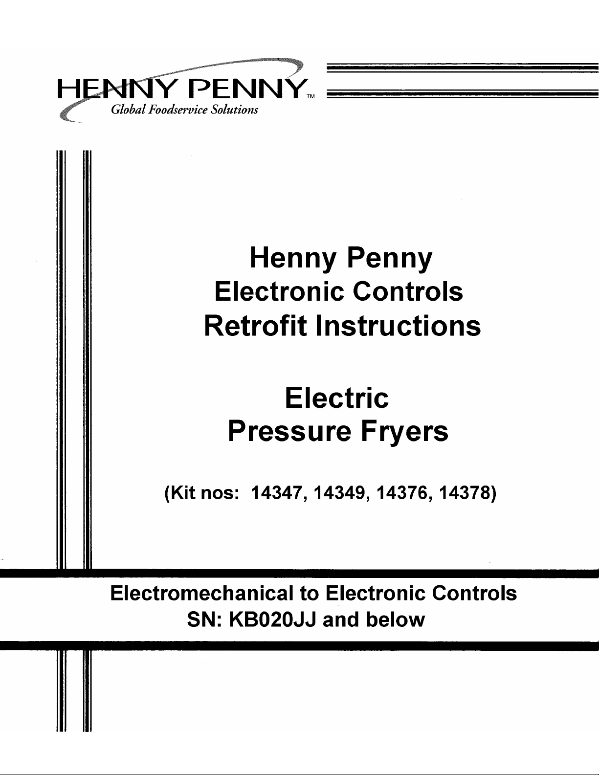
2. Remove the Phillip’s head screws from the control
Figure 1-1 panel. Figure 1-1.
3. Cut wire ties and mark the wires to the pump(connected
to the power switch) and unplug them. Figure 1-2.
Hint: A 500/600/561 Manual may help in referring to the
original wiring diagram.
.
Figure 1-2
602 1-1
Page 4
Electronic Controls Retrofit
1-2. REMOVING “OLD”
CONTROLS (Continued)
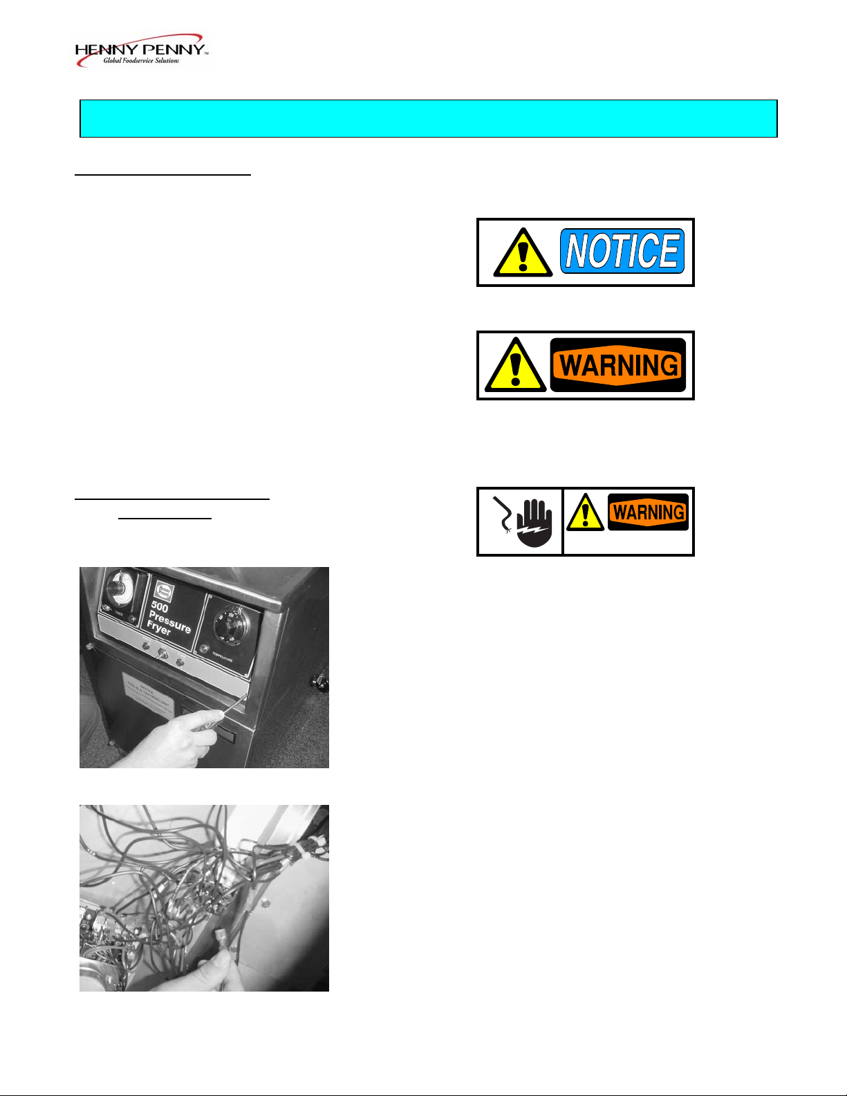
4. Mark and disconnect the wires to the pressure solenoid,
at the N/C terminals on the timer. Figure 1-3.
Figure 1-3 5. Remove thermostat bulb, capillary, and bracket from
the elements and pull from frypot. Figure 1-4.
6. Disconnect and remove the remaining control wires and
connectors.
a. Disconnect remaining power switch wires.
Figure 1-4 b. Disconnect indicator light, drain switch and high
limit wires.
c. Disconnect 15 amp fuse holder wires from Primary
Contactor.
7. Pull “old” control from unit.
Figure 1-5
8. Remove L1, L2, & L3 from Primary Contactor.
Figure 1-5.
1-2 602
Page 5

Electronic Controls Retrofit
1-2. REMOVING “OLD”
CONTROLS (Continued)
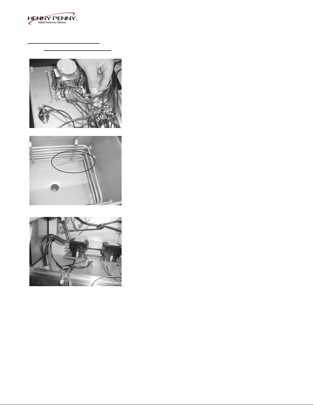
9. Remove the 3 wires from the heating elements.
Figure 1-6.
If element terminals look heavily corroded, remove the
wires at the contactor instead of the elements. Remove
the wires from the mercury contactor, from the kit, and
pull the amp rings from the wires. Slide the appropriate
Figure 1-6 colored ring over the line wire and attach to mercury
contactor. See below. Black=L1 Red=L2 Orange=L3 Using a wire tie, fasten each ring up on the line wire, so it doesn’t slide down against the contactor terminal.
Black
Red
Orange
Figure 1-7
10. Remove the 2 bolts securing the contactor bracket and
remove entire contactor assembly. Figure 1-7.
11. Remove pressure solenoid coil. Figure 1-8.
Figure 1-8
602 1-3
Page 6

Electronic Controls Retrofit
1-3. INSTALLING “NEW” 1. Install new temperature probe. See instruction below.
CONTROLS
Figure 1-9
1-4 602
Page 7

Electronic Controls Retrofit
1-3. INSTALLING “NEW” 2. Install the 24 VAC solenoid coil from kit.
CONTROLS (Continued)
3. Install 2 sheets of insulation against frypot wall, thin
sheet first. Figure 1-10.
Figure 1-10
4. Locate the wire harness with the 6-pin red connector.
a. Connect the yellow wires to high limit wires using
wire nuts.
b. Connect the white wires to the drain switch wires
using wire nuts. Figure 1-11.
Figure 1-11
5. Install contactor assembly from kit. Figure 1-12.
6. Connect the solenoid wires to the red wires in positions
1 & 2 of the 12-pin connector.
Figure 1-12
Insure these are not connected to the pump by accident.
602 1-5
Page 8

Electronic Controls Retrofit
1-3. INSTALLING “NEW” 7. Locate the harness with the 2-pin white connector and
CONTROLS (Continued)
connect the wires to the pump wires.
Be sure to connect these to the pump wires and NOT
the pressure solenoid wires, or the 24V pressure
solenoid coil will be damaged when the pump is
turned on.
8. Install the two threaded standoffs in the lower holes,
where the front panel mounting screws were removed.
Tighten the nuts on the threads on the back side of the
sheet metal to prevent the standoffs from turning.
Figure 1-13.
Figure 1-13 9. Wire tie the wires to keep them from interfering with
the components, except for the probe and amp
monitoring connector. Pull the wires to the left side of
the controls, but don’t bundle the power switch wires
with the others for ease of panel removal.
10. Plug all connectors, including the probe and new
transformer harness into the back of the control.
The connector from the transformer can plug into two
connectors on the control. This is to select the voltage
tap on the transformer for 208V or 240V. Determine
the proper voltage and insert the plug into that
connector.
11. Secure the panel into place with screws previously
removed.
12. Supply power to the fryer and program the low amp
setting in Special Program Mode. (Power switch off)
Computron 8000 installations see next page, Chick-
fil-A installations see page 1-8.
1-6 602
Page 9

Electronic Controls Retrofit
1-3. INSTALLING “NEW”
CONTROLS (Continued)
For Computron 8000 Retrofits Only!
The Computron 8000 controls monitors the amperage
to the elements. The nominal amp setting must be
programmed after installation and before operation, or
a constant warning shows on the display when the
controls are turned on.
a. Press and hold for 5 seconds until
"L-2" and "LEVEL 2", followed by, “SP PROG"
and “ENTER CODE shows in the display.
b. Enter code 1, 2, 3, and "SP- 1 ", "TEMP, UNITS"
shows in the display.
c. Press until “SP-12”, “AMPS RDG,
NOMINAL” shows in display.
d. Check the amp reading on the right side of display
(ex: “37 A”) with the amp reading on the data
plate. If readings are different, use to
change display to match data plate.
e. Press and hold to exit Special Program Mode
and unit is now ready for operation.
602 1-7
Page 10

Electronic Controls Retrofit
1-3. INSTALLING “NEW”
CONTROLS (Continued)
For Chick-fil-A Retrofit Only!
Upon initial start-up “CLOCK SET” shows in display. Set
the clock to your time, following prompts on the display, or
see section 2-2 in Operating Instructions for help.
Then display asks if the peanut oil is NEW or OLD. The
controls automatically adjust the peanut oil temperature to
the age of the peanut oil. If the oil is old, use to set
the number of days of old peanut oil.
Set Nominal Voltage
The controller continually monitors the line voltage supplied
to the fryer (when the fryer is on). If the line voltage drops
below [90%] of its nominal value, the controller signals a
“LOW VOLTAGE” alarm. Also, once the voltage is set, the
controls automatically set the nominal amperage value. This
nominal voltage value must be programmed after retrofit
installation to avoid nuisance alarms.
1. Press and hold for 5 seconds until “L 2 LEVEL 2”
shows in the display. Then release 5 times until
“TECH” shows in the display.
2. Enter code 1, 1, 2, 2, 1, 1, 2, 2.
3. Press and release 10 times until “T-11” shows in
the display.
4. Use to match the displayed value with the
voltage showing on the data plate, on the door of the
fryer.
1-8 902
Page 11

1-8 703
Electronic Controls Retrofit
Page 12

Electronic Controls Retrofit
Parts List:
Item Part
Number Number Description Qty
1 32633 Card – C8000 Std. Product Menu 1
1 32634 Card – C8000 Blank Menu 1
1 61725 Card – CFA Menu – Pressure Fryer 1
2 29898 Power Switch 1
3 27303 Decal – Control –Bent – C8000 1
3 61576 Decal – Control – Bent – CFA 1
4 55167 Assembly – Probe/Compression Fitting 1
5 16738 High Limit – 450 degree F. 1
6 29521 Assembly – Transformer 1
7 18364 Assembly – Fuse Holder – 15 amp 2
7 EF02-007 Fuse – 15 amp 2
8 29510 Contactor – Mercury – 24 VAC 1
9 51795 Contactor – 24 VAC 1
10 32613RB Assembly – Control 8000 Bent Panel (SN: KB020JJ and below) 1
10 24319RB Assembly – Control CFA – Bent Panel (SN: KB020JJ and below) 1
11 26974 Assembly – Speaker 1
12 29515 Solenoid – 24 Volt – 60 Hz. 1
12 29698 Solenoid – 24 Volt – 50 Hz. 1
12 29547 Solenoid Coil – 24 Volt – 50/60 Hz. 1
13 63294 Insulation – Fryer Pot – ¼” 1
14 63295 Insulation – Fryer Pot – 1/8” 1
15 24347 Assembly – Current Sense Xformers 1
802 1-9
 Loading...