

TECHNICAL MANUAL
Henny Penny
Open Fry Station
Model OFE/OFG-323
Model OFE/OFG-322
Model OFE/OFG-321
Model OFE/OFG-324
Model OEA/OGA-323
Model OEA/OGA-322
Model OEA/OGA-321
Model OEA/OGA-324
Model ODE/ODG-323
Model OFE/OFG-321,322,323,324
This manual should be retained in a convenient location for future reference.
A wiring diagram for this appliance is located on the inside of the right side panel.
Post in a prominent location, instructions to be followed in event user smells gas. This information shall
be obtained by consulting the local gas supplier.
Do not obstruct the flow of combustion and ventilation air. Adequate clearance must be left all around
appliance for sufficient air to the combustion chamber.
The Model OFG/OGA-32X open fryer is equipped with a continuous pilot. But the open fryer can not be
operated without electric power. The unit will automatically return to normal operation when power is
restored.
To avoid a fire, keep appliance area free and clear from combustibles.
Improper installation, adjustment, alteration, service or maintenance can cause property damage,
injury or death. Read the installation, operating and maintenance instructions thoroughly before
installing or servicing this equipment.
FOR YOUR SAFETY, DO NOT STORE OR USE GASOLINE OR OTHER FLAMMABLE
VAPORS AND LIQUIDS IN THE VICINITY OF THIS OR ANY OTHER APPLIANCE.
FM06-008
Revised 06-04-2012

Model OFE/OFG-321,322,323,324
TABLE OF CONTENTS
Section Page
Section 1. TROUBLESHOOTING ...................................................................................................1-1
1-1. Introduction .............................................................................................................1-1
1-2. Safety ......................................................................................................................1-1
1-3. Troubleshooting ......................................................................................................1-2
1-4. Error Codes .............................................................................................................1-5
Section 2. MAINTENANCE .............................................................................................................2-1
2-1. Introduction .............................................................................................................2-1
2-2. Maintenance Hints ..................................................................................................2-1
2-3. High Temperature Limit Control (Gas Units) .........................................................2-1
2-4. Complete Control Panel Replacement ...................................................................2-4
2-5. Power Switch ..........................................................................................................2-4
2-6. Temperature Probe Replacement ............................................................................2-5
2-7. Flame Sensor (Gas Units) .......................................................................................2-8
2-8. Pilot/Ignitor Assembly ............................................................................................2-9
2-9. Ignitor Module ........................................................................................................2-10
2-10. Transformer Replacement .......................................................................................2-10
2-11. I/O Power Supply Boards Assembly .......................................................................2-11
2-12. Vacuum Switch .......................................................................................................2-11
2-13. Speaker Assembly (Gas Units) ...............................................................................2-12
2-14. Drain Microswitch ..................................................................................................2-13
2-15. Filter Switch ............................................................................................................2-13
2-16. Gas Control Valve Assembly ..................................................................................2-14
2-17. Blower Motor Assembly .........................................................................................2-16
2-18. Heating Elements (Electric Only) ...........................................................................2-18
2-19. Heating Contactors (Electric Only) .........................................................................2-21
2-20. Speaker Assembly (Electric Units) .........................................................................2-23
2-21. High Temperature Limit Control (Electric Units) ..................................................2-24
2-22. Autolift Actuator (motor) Replacement (if Applicable) .........................................2-25
2-23. Autolift Transformer Replacement (if Applicable) ................................................2-28
2-24. Autolift PC Board Replacement (if Applicable) .....................................................2-28
Wiring Diagrams
Section 3. PARTS INFORMATION .................................................................................................3-1
3-1. Introduction .............................................................................................................3-1
3-2. Genuine Parts ..........................................................................................................3-1
3-3. When Ordering Parts ...............................................................................................3-1
3-4. Prices .......................................................................................................................3-1
3-5. Delivery ...................................................................................................................3-1
3-6. Warranty ..................................................................................................................3-1
3-7. Recommended Spare Parts for Distributors ............................................................3-1
i 109
Model OFE/OFG-321,322,323,324
DANGER INDICATES AN IMMINENTLY
HAZARDOUS SITUATION WHICH, IF NOT
AVOIDED, WILL RESULT IN DEATH OR
SERIOUS INJURY.
WARNING indicates a potentially hazardous situation
which, if not avoided, could result in death or serious
injury.
CAUTION used with the safety alert symbol indicates a
potentially hazardous situation which, if not avoided,
could result in minor or moderate injury.
CAUTION used without the safety alert symbol indicates a
potentially hazardous situation which, if not avoided, may
result in property damage.
NOTICE is used to highlight especially important
information.
SAFETY ALERT SYMBOL is used with DANGER,
WARNING or CAUTION which indicates a personal
injury type hazard.
SECTION 1. TROUBLESHOOTING
1-1. INTRODUCTION This section provides troubleshooting information in the form of
an easy to read table.
If a problem occurs during the first operation of a new fryer,
recheck the Installation Section of the Operator’s Manual.
Before troubleshooting, always recheck the Operation Section of
the Operator’s Manual.
1-2. SAFETY Where information is of particular importance or is safety related,
the words DANGER, WARNING, CAUTION, or NOTE are used.
Their usage is described on the next page:
203 1-1
Model OFE/OFG-321,322,323,324
1-3. TROUBLESHOOTING To isolate a malfunction, proceed as follows:
1. Clearly define the problem, or symptom and when it
occurs.
2. Locate the problem in the troubleshooting table.
3. Review all possible causes, then one at a time, work
through the list of corrections until the problem is solved.
If maintenance procedures are not followed correctly,
injuries and/or property damage could result.
PROBLEM CAUSE CORRECTION
With the switch in Open circuit Check to see if unit is plugged in
the POWER position,
fryer is completely Check breaker or fuse at supply box
inoperative
Check POWER switch per Power Switch
Section; replace if defective
Check voltage at wall receptacle
Check cord and plug
Shortening will not Faulty contactor Check contactor per Heating Contactors
heat but lights are on (elec. model) Section
Faulty gas control Check gas control valve per Gas Control
valve (gas model) Valve Assembly Section
Faulty temperature Check temperature probe per Temperature
probe Probe Replacement Section; “E-6A or B”
Faulty high limit Check high limit per the appropriate High
Temperature Limit Control Section; “E-10”
Faulty drain switch Check drain switch per Drain Microswitch
Section; “E-15"
1-2 203

Model OFE/OFG-321,322,323,324
1-3. TROUBLESHOOTING(Continued)
PROBLEM CAUSE CORRECTION
Heating of Low or improper Use a meter and check the receptacle
shortening too voltage (elec. unit) voltage against the data plate
slow
Weak or burnt out Check heating elements per Heating
elements (elec. unit) Elements Section
Wire(s) loose Tighten
Burnt or charred Replace wire and clean connectors
wire connection
Faulty contactor Check contactor per Heating Contactors
Section
Supply line too small Increase supply line size; refer to
- low gas volume Installation Section of Operator’s Manual
(gas unit)
Improper ventilation Refer to Installation Section of Operator’s
Manual
Shortening Temperature probe Calibrate temperature probe if 10 off;
overheating needs calibration if more than 10 off, replace temperature
probe
Mercury contactor Check mercury contactor for not opening;
stuck closed replace if necessary (elec. unit)
Bad control board Replace control board if heat indicator stays
on past ready temperature
Foaming or boiling Water in shortening At end of cook cycle, drain shortening and
over of shortening clean
Improper or bad Use recommended shortening
shortening
Improper filtering Refer to the Filtering the Shortening
Section in Operator’s Manual
Improper rinsing Clean and rinse the frypot; then dry
after cleaning fryer thoroughly
203 1-3

Model OFE/OFG-321,322,323,324
1-3. TROUBLESHOOTING
(Continued)
PROBLEM CAUSE CORRECTION
Shortening will not Drain valve clogged Open valve, force cleaning brush through
drain from frypot with crumbs drain
Drain valve will not Replace cotter pins in valve coupling
open by turning
handle
Filter motor runs Pump clogged Remove pump cover and clean
but pumps shortening
slowly Filter line connection Tighten all filter line connections
loose
Solidified shortening Clear all filter lines of solidified shortening
in lines
Filter switch on but Defective switch Check/replace switch per Filter Switch
motor does not run Section
Defective motor Check/replace motor
Motor thermal Reset thermal switch on filter motor
protector tripped
Motor hums but Clogged lines or Remove and clean pump and lines
will not pump pump
Replace pump seal, rotor and rollers
1-4 203
Model OFE/OFG-321,322,323,324
1-4. ERROR CODES In the event of a control system failure, the digital display shows
an error message. These messages are coded: “E-4”, “E-5”, “E-
6A”, “E-6B”, “E-10”, “E-15”, “E-20”, “E-31”, “E-41”, “E-46”,
and “E-92”. A constant tone is heard when an error code is
displayed, and to silence this tone, press any button.
DISPLAY CAUSE PANEL BOARD CORRECTION
“E-4” Control board Turn switch to OFF position, then turn switch back to ON;
overheating if display shows “E-4”, the control board is getting too hot;
check the louvers on each side of the unit for obstructions
“E-5” Shortening Turn switch to OFF position, then turn switch back to ON;
overheating if display shows “E-5”, the heating circuits and temperature
probe should be checked
“E-6A” Temperature Turn switch to OFF position, then turn switch back to ON;
probe open if display shows “E-6A” the temperature probe should be
checked
“E-6B” Temperature Turn switch to OFF position, then turn switch back to ON;
probe shorted if display shows “E-6B” the temperature probe should be
checked to replace, per Temperature Probe Replacement
Section
“E-10” High limit Reset the high limit by manually pushing up on the red
reset button; if high limit does not reset, high limit must be
replaced per High Limit Temperature Control Section
“E-15” Drain switch Close drain, using the drain valve handle; if display still
failure shows “E-15”, check the drain microswitch per Drain
Microswitch Section
“E-41”, Programming Turn switch to OFF, then back to ON. If display shows any
“E-46” failure of the error codes, try to reinitialize the control (Special
Program Mode Section of Operator’s Manual). If error
Code persists, replace the control panel per Complete
Control Panel Replacement Section
203 1-5
Model OFE/OFG-321,322,323,324
1-4. ERROR CODES
(Continued)
DISPLAY CAUSE PANEL BOARD CORRECTION
“E-20A” Vacuum Press the timer button to try the ignition process again,
switch failure and if “E-20A” persists, check the air switch per Vacuum
(stuck closed) Switch Section
“E-20B” Draft fan or Press the timer button to try the ignition process again,
vacuum and if “E-20B” persists, check the vacuum switch per
switch failure Vacuum Switch Section or the blower motor per Blower
(stuck open) Motor Assembly Section
“E-20C” Ignition modules Press the timer button to try the ignition process again; if
not responding “E-20C” persists, check the ignition module per Ignitor
Module Section or the spark ignitor per Pilot/Ignitor
Assembly Section, or the I/O board per I/O Power Supply
Boards Assembly Section
“E-20D” Pilots not lit or Press the timer button to try the ignition process again; if
no flame sense “E-20D” persists, check the ignition module per Ignitor
Module Section, or the I/O board per I/O Power Supply
Boards Assembly Section, or the flame sensor per Flame
Sensor Section
“E-31” Fan switch jumper Check for jumper wire on 12-pin connector & add if
wire missing missing
“E-47” Analog converter Turn switch to OFF, then back to ON; if “E-47” persists,
chip or 12 volt replace the I/O board, or the PC board; if speaker
supply failure tones are quiet, probably I/O board failure
“E-48” Input system Replace PC board
error
“E-70” Faulty POWER Check POWER switch checked, along with its wiring;
switch or switch replace input/output board if necessary
wiring; faulty I/O
board
“E-92” 24 VAC fuse Check for shorted component in 24 volt circuit;
on I/O open (i.e., high limit, drain switch, vacuum switch)
1-6 109
Model OFE/OFG-321,322,323,324
SECTION 2. MAINTENANCE
2-1. INTRODUCTION This section provides procedures for the checkout and replacement
of the various parts used within the fryer. Before replacing any
parts, refer to the Troubleshooting Section. It will aid you in
determining the cause of the malfunction.
2-2. MAINTENANCE HINTS 1. You may need to use a multimeter to check the electric
components.
2. When the manual refers to the circuit being closed, the
multimeter should read zero unless otherwise noted.
3. When the manual refers to the circuit being open, the
multimeter will read infinity.
2-3 HIGH TEMPERATURE
LIMIT CONTROL The high temperature limit control is a safety, manual reset control
(Gas Units) that senses the temperature of the shortening. If the shortening
temperature exceeds 425F (218C), this switch will open
and shut off heat to the frypot. When the temperature of the
shortening drops to a safe operation limit, the control must be
manually reset by pressing the red reset button. The red reset
button is located under the control panel, in the front of the fryer.
This will allow heat to be supplied to the frypot once again.
Checkout Before replacing a high temperature limit control, check to see
that its circuit is closed.
The shortening temperature must be below 380F
(193C) to accurately perform this check.
Checkout:
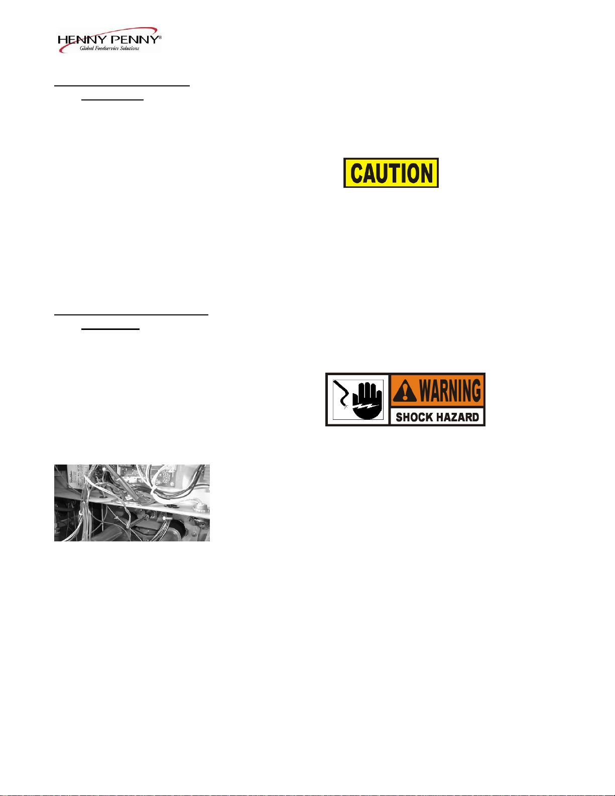
1. Remove electrical power supplied to fryer.
To avoid electrical shock or property damage, move the
POWER switch to OFF and disconnect main circuit
breaker, or unplug cord at wall receptacle.
2. Remove the control panel.
203 2-1
Model OFE/OFG-321,322,323,324
2-3 HIGH TEMPERATURE
LIMIT CONTROL
(Continued)
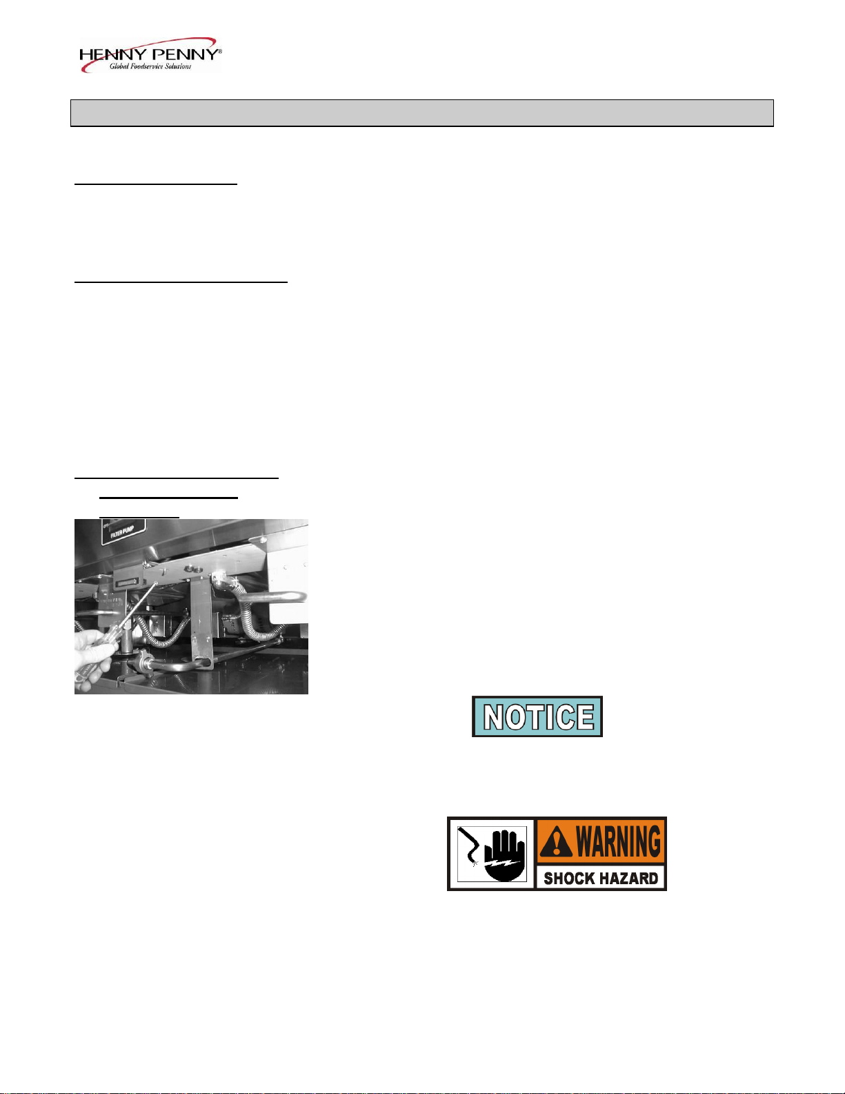
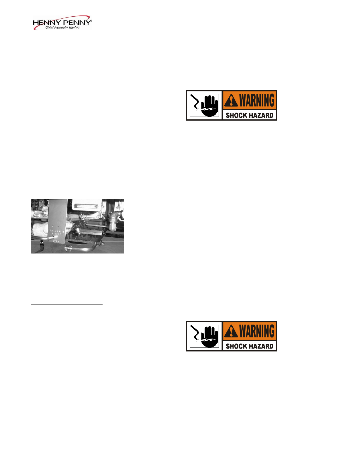
3. Remove the two nuts securing the high limit bracket to the unit
and pull the bracket from the unit.
4. Remove the two screws securing the high limit to the bracket,
and remove the high limit from the bracket.
5. Remove the two electrical wires from the high temperature
limit control.
6. Manually reset the control, then check for continuity between
the two terminals after resetting the control. If the circuit is
open, replace the control, then continue with this procedure.
(If the circuit is closed, the high limit is not defective. Reconnect the two electrical wires.)
Replacement:
To avoid electrical shock or property damage, move the
POWER switch to OFF and disconnect main circuit
breaker, or unplug cord at wall receptacle.
1. If the tube is broken or cracked, the control will open, shutting
off electrical power to the heat circuit. The control cannot be
reset, and it will continuously click when pushed.
2. Drain the shortening from the frypot and discard. A substance
in the tube could contaminate the shortening.
3. Remove the control panel.
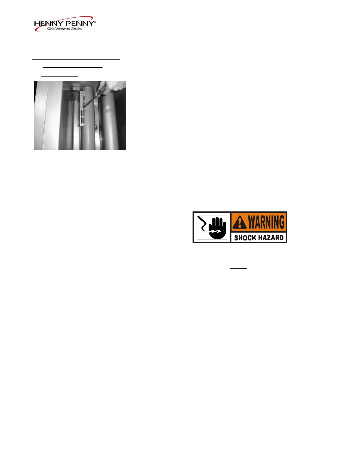
4. Loosen small inside screw nut on capillary tube.
2-2 203
2-3 HIGH TEMPERATURE
LIMIT CONTROL
(Continued)
Model OFE/OFG-321,322,323,324
5. Remove the bracket from the heat tube covering the high limit
bulb.
6. Straighten the capillary tube behind the pot wall.
7. Pull the high limit bulb through the retainers on the heat tube.
8. Remove the larger outside nut that threads into the pot wall.
9. Remove the defective high limit from the control panel area.
10. Insert new high limit into bracket and replace wires.
11. Uncoil capillary line, starting at capillary tube, and insert
through frypot wall.
To avoid electrical shock or other injury, run the capillary
line under and away from all electrical power wires and
terminals. The tube must never be in such a position where
it could accidentally touch the electrical power terminals.
12. Insert capillary line through brackets on heat tube, and then
pull back through pot wall until capillary bulb is secure in
brackets.
13. Pull excess capillary line from pot and tighten nut into
frypot wall.
14. With excess capillary line pulled out, tighten smaller nut.
15. Replace bracket on heat tube covering the high limit bulb.
16. Replace front panel.
17. Refill frypot with shortening.
203 2-3
Model OFE/OFG-321,322,323,324
2-4. COMPLETE CONTROL
PANEL REPLACEMENT Should the control board become inoperative, follow these
instructions for replacing the board.
1. Remove electrical power supplied to the unit.
To avoid electrical shock or property damage, move the
POWER switch to OFF and disconnect main circuit
breaker, or unplug cord at wall receptacle.
2. Remove the four screws securing the control panel and lift
out.
3. Unplug the wire connectors going to the control board.
4. Install new control panel in reverse order.
When plugging connectors onto new control panel, be sure
the connectors are inserted onto all of the pins, and that the
connectors are not forced onto the pins backwards. If not
connected properly, damage to the board could result.
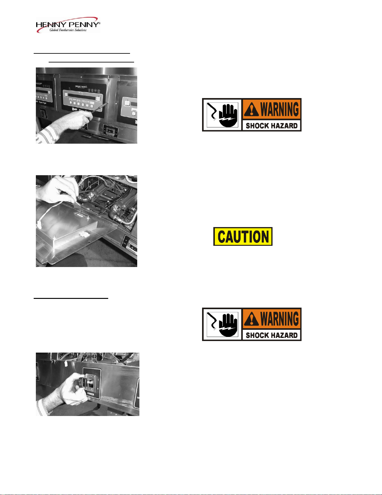
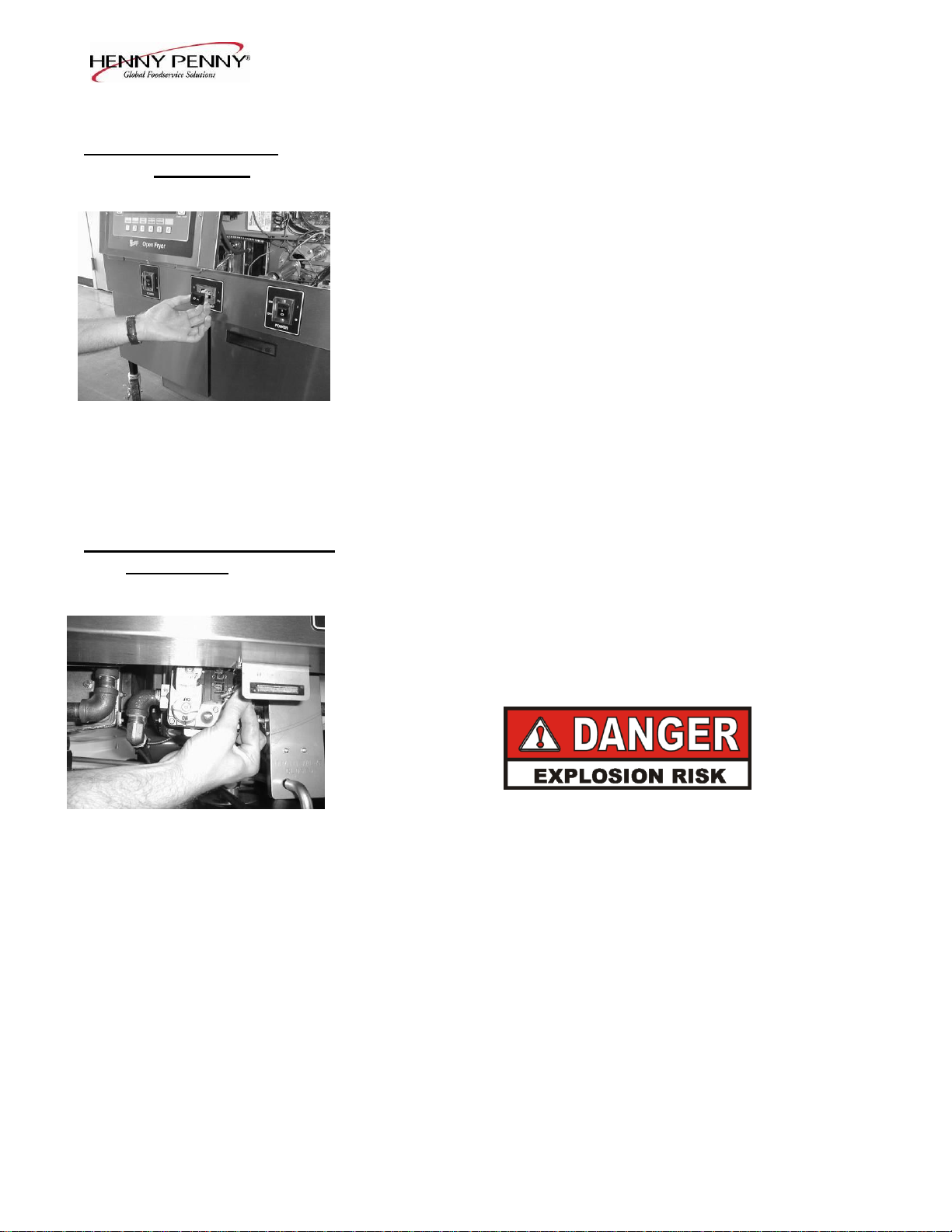
2-5. POWER SWITCH 1. Remove electrical power supplied to fryer.
To avoid electrical shock or property damage, move the
POWER switch to OFF and disconnect main circuit
breaker, or unplug cord at wall receptacle.
2. Remove control panel.
3. Label and remove the wires from the switch. With test
instrument, check across the terminals of the switch with
the switch in the ON position, then in the OFF position.
With the switch in the ON position, the circuit should be
closed. With the switch in the OFF position, the circuit
should be open. If the switch checks defective, replace by
continuing with this procedure.
2-4 203
Model OFE/OFG-321,322,323,324
2-5. POWER SWITCH
(Continued) 4. With control panel removed, and the wires off the switch, push
in on tabs on the switch to remove from panel.
5. Replace with new switch, and reconnect wires to switch.
6. Replace the control panel.
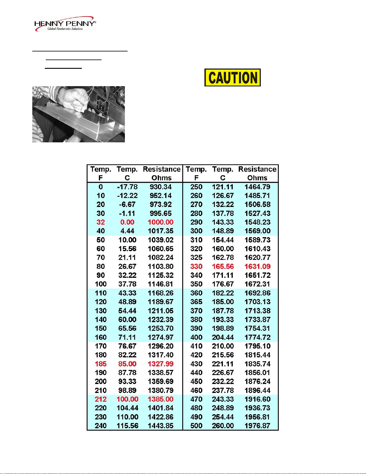
2-6. TEMPERATURE PROBE The temperature probe relays the actual shortening temperature to
REPLACEMENT the control board. If it becomes disabled, “E-6B” will show in the
display. Also, if the shortening temperature is out of calibration by
more than 10°F or C°, the temperature probe should be replaced.
An Ohm check can be performed also. See chart on page 2-7.
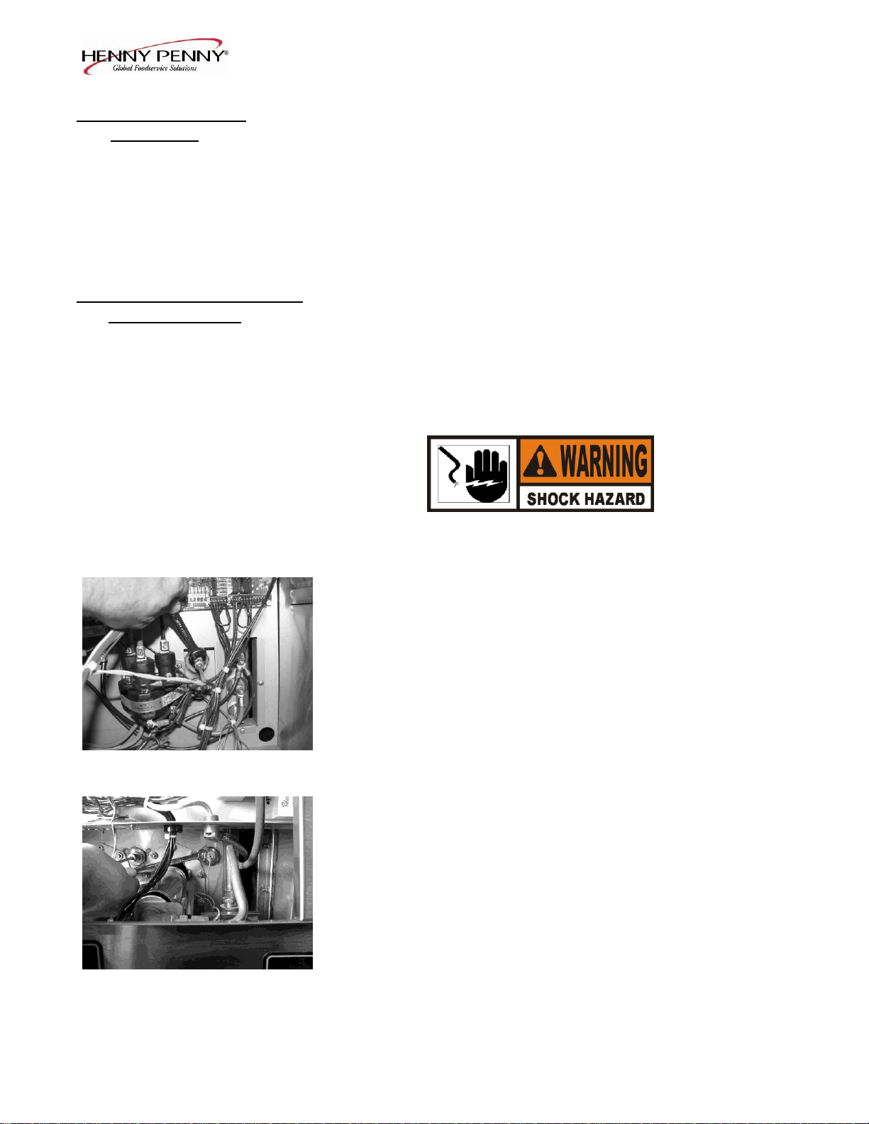
1. Remove electrical power supplied to the fryer.
To avoid electrical shock or property damage, move the
power switch to OFF and disconnect main circuit
Electric breaker, or unplug cord at wall receptacle.
2. Drain the shortening from the frypot.
3. Remove the control panel.
Gas
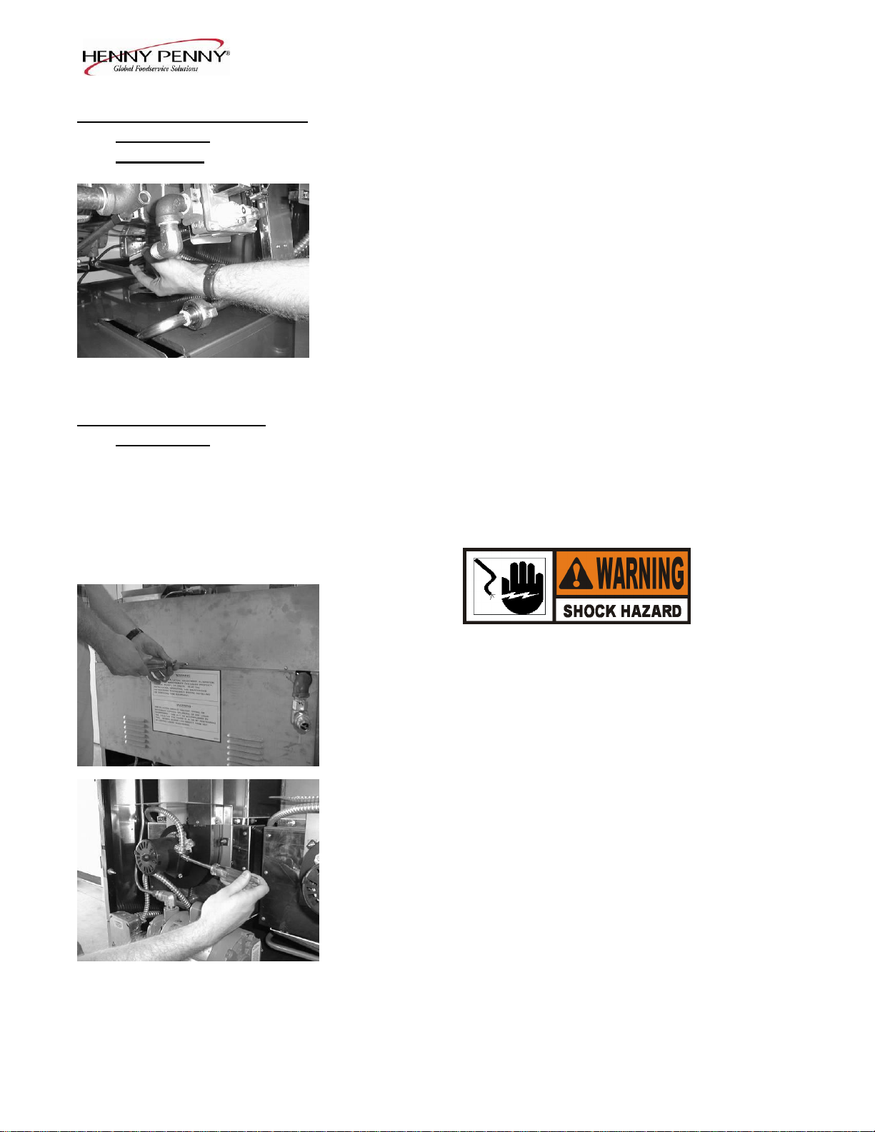
4. Using a 1/2" wrench, remove the nut on the compression
fitting.
5. Remove the temperature probe from the frypot.
6. Follow the appropriate instructions, on the following page,
depending upon the type of fryer, gas or electric.
606 2-5

2-6. TEMPERATURE PROBE
REPLACEMENT
(Continued) ELECTRIC
Model OFE/OFG-321,322,323,324
GAS
2-6 606
Model OFE/OFG-321,322,323,324
2-6. TEMPERATURE PROBE 7. Tighten the compression nut hand tight and then a half turn
REPLACEMENT with wrench.
(Continued)
Excess force will damage temperature probe.
8. Connect new temperature probe to PC board and replace
control panel.
9. Replace shortening.
10. Turn power on and check out fryer.
606 2-7
Model OFE/OFG-321,322,323,324
2-7. FLAME SENSOR The flame sensor recognizes the pilot flame and allows gas to
(Gas Units) continue to the pilot. The flame sensor must send a minimum of
two (2) micro amps to the ignition module. The pilot flame should
be split in two by the flame sensor, causing the flame sensor to be
bright red in color.
1. Remove electrical power supplied to the unit.
To avoid electrical shock or property damage, move the
POWER switch to OFF and disconnect main circuit
breaker, or unplug cord at wall receptacle..
2. To access flame sensor, open the filter doors in the front of the
unit. Follow the small gauge yellow wire running to the sensor
behind the pilot assembly.
3. Disconnect the flame sense wire from the flame sensor.
4. Using a pair of needle nosed pliers, pull the flame sensor out
of the pilot assembly bracket.
5. Insert new flame sensor and reconnect flame sensor wire.
6. Turn power on and check fryer.
2-8 203
Model OFE/OFG-321,322,323,324
2-8. PILOT / IGNITOR The Henny Penny open fryer (gas) has electronic spark ignition
ASSEMBLY that lights a standing pilot. The gap between the spark electrode
and the pilot hood should be set at 1/8 of an inch.
1. Remove electrical power supplied to the unit.
To avoid electrical shock or property damage, move the
POWER switch to OFF and disconnect main circuit
breaker, or unplug cord at wall receptacle.
TO AVOID PERSONAL INJURY OR PROPERTY
DAMAGE, BEFORE STARTING THIS
PROCEDURE, MOVE THE MAIN POWER SWITCH
TO THE OFF POSITION. DISCONNECT THE MAIN
CIRCUIT BREAKERS AT THE CIRCUIT BREAKER
BOX OR UNPLUG SERVICE CORD FROM WALL
RECEPTACLE. TURN OFF THE MAIN GAS
SUPPLY TO THE FRYER AND DISCONNECT AND
CAP THE MAIN SUPPLY LINE TO FRYER, OR
POSSIBLE EXPLOSION COULD RESULT.
2. Remove the control panel as discussed in Complete Control
Panel Replacement Section.
3. Disconnect the pilot gas line fitting at the pilot assembly with
a ½ inch wrench.
4. With a Phillips head screwdriver, remove the two screws
securing the pilot assembly to the mounting bracket.
5. Remove the flame sensor wire from the flame sensor.
6. Follow the wire from the spark ignitor back to the module, and
remove wire from module.
7. After removing assembly from unit, pull the flame sensor out
of the bracket as discussed in section 6-7. Insert flame sensor
into new pilot/ignitor assembly.
8. Reinstall the new pilot/ignitor assembly in reverse order. Be
extremely careful not to cross thread the pilot gas line fitting.
203 2-9
Model OFE/OFG-321,322,323,324
2-9. IGNITOR MODULE During normal operation, the ignition modules send 24 volts to the
ignitors and gas control valve. If a module does not sense a pilot
flame, the module starts the ignition process again. But, if a pilot
light goes out for longer that 10 seconds, or it goes out 3 times within
10 seconds, the module keeps the 24 volts from reaching the gas
control valve. The burners shut down.
1. Remove electrical power supplied to the unit.
To avoid electrical shock or property damage, move the
POWER switch to OFF and disconnect main circuit
breaker, or unplug cord at wall receptacle.
2. Remove the control panel as discussed in Complete Control Panel
Replacement Section.
3. Label and remove the wires at module.
4. Using a 3/8 inch nut driver, remove the keps nuts securing the
module to the shroud.
5. Install new module in reverse order.
2-10. TRANSFORMER The transformer reduces voltage down to accommodate those
components with low voltage.
1. Remove electrical power supplied to the unit.
To avoid electrical shock or property damage, move the
POWER switch to OFF and disconnect main circuit
breaker, or unplug cord at wall receptacle.
2. Remove the control panel as discussed in Complete Control Panel
Replacement Section.
3. Squeeze on the wire connector at the I/O board assembly to
disconnect the wires from the transformer.
4. Using a Phillips head screwdriver, remove the two screws
securing the transformer to the shroud.
5. Install the new transformer in reverse order.
2-10 203
Model OFE/OFG-321,322,323,324
2-11. I/O POWER SUPPLY
BOARD ASSEMBLY The input/output power supply board assembly distributes
voltage to the various components in the fryer. The board also
receives information from components in the fryer.
1. Remove electrical power supplied to the unit.
To avoid electrical shock or property damage, move the
POWER switch to OFF and disconnect main circuit
breaker, or unplug cord at wall receptacle.
2. Remove the control panel as discussed in Complete Control
Panel Replacement Section.
3. Disconnect the wire assemblies from the board.
4. Using a nut driver or wrench, remove the four keps nuts
securing the board to the shroud.
5. Install the new I/O board assembly in reverse order.
2-12. VACUUM SWITCH The vacuum switch senses the airflow from the induction blower.
If the airflow is reduced below a set amount, the switch will open
and the I/O board will cut power to the gas control valve, which
will shut the pilot flame off.
1. Remove electrical power supplied to the unit.
To avoid electrical shock or property damage, move the
POWER switch to OFF and disconnect main circuit
breaker, or unplug cord at wall receptacle.
2. Remove the control panel as discussed in Complete Control
Panel Replacement Section.
3. Remove the air hose from the vacuum switch.
4. Label and remove wires from vacuum switch.
203 2-11
Model OFE/OFG-321,322,323,324
2-12. VACUUM SWITCH
(Continued) 5. Using a Phillips head screwdriver, remove the screws securing
the vacuum switch to the shroud.
6. Install the new vacuum switch in reverse order.
To avoid property damage, do not tamper with, or disas semble this component. It is set and sealed from the
factory and is not to be adjusted.
2-13. SPEAKER ASSEMBLY The speaker assembly emits audible signals to let the operator
(Gas Units) know when cooking and hold times are finished.
1. Remove electrical power supplied to the unit.
To avoid electrical shock or property damage, move the
POWER switch to OFF and disconnect main circuit
breaker, or unplug cord at wall receptacle.
2. Remove the control panel as discussed in Complete Control
Panel Replacement Section.
3. Using a Phillips head screwdriver, remove the four screws
securing the speaker to the shroud.
4. Install new speaker in reverse order. When plugging connector
into control board, be sure to align pins into connector
correctly.
2-12 203
Model OFE/OFG-321,322,323,324
2-14. DRAIN MICROSWITCH Upon turning the drain handle, the drain microswitch circuit
should open, cutting off the pilot flame. This will prevent the fryer
from heating while shortening is being drained from the frypot.
1. Remove electrical power supplied to the unit.
To avoid electrical shock or property damage, move the
POWER switch to OFF and disconnect main circuit
breaker, or unplug cord at wall receptacle.
2. The following check should be made to determine if the drain
microswitch is defective.
a. Remove the two screws securing the microswitch to the
drain rod valve bracket.
b. Remove wires from the switch.
c. Check for continuity across the two outside terminals of the
drain switch. If the circuit is open, the drain switch is
defective. The circuit should only be opened by pressing on
the actuator of the drain switch.
3. Replace switch in reverse order.
2-15. FILTER SWITCH
1. Remove electrical power supplied to the unit.
To avoid electrical shock or property damage, move the
POWER switch to OFF and disconnect main circuit
breaker, or unplug cord at wall receptacle.
203 2-13
Model OFE/OFG-321,322,323,324
2-15. FILTER SWITCH
(Continued) 2. Remove the control panel above the switch.
3. Label and remove the wires from the switch. With test
instrument, check across the terminals of the switch with the
switch in the ON position, and then in the OFF position. With
the switch in the ON position, the circuit should be closed.
With the switch in the OFF position, the circuit should be open.
If the switch checks defective, replace it by continuing with this
procedure.
4. With wires removed from the switch, push in on tabs on the
switch and remove switch from the panel.
5. Push new switch into panel and reconnect wires.
2-16. GAS CONTROL VALVE
ASSEMBLY The gas control valve assembly controls the flow of gas to the pilot
and the main burner. The valve has two 24 volt coils, which are
regulated by terminals P and M on the valve. The C terminal is the
common terminal. For gas flow to the pilot, 24 VAC must be
present between the P and C terminals. For gas flow to the main
burner, 24 VAC must be present between the M and C terminals.
TO AVOID PERSONAL INJURY OR PROPERTY
DAMAGE, BEFORE STARTING THIS
PROCEDURE, MOVE THE MAIN POWER SWITCH
TO THE OFF POSITION. DISCONNECT THE MAIN
CIRCUIT BREAKERS AT THE CIRCUIT BREAKER
BOX OR UNPLUG SERVICE CORD FROM WALL
RECEPTACLE. TURN OFF THE MAIN GAS
SUPPLY TO THE FRYER AND DISCONNECT AND
CAP THE MAIN SUPPLY LINE TO FRYER, OR
POSSIBLE EXPLOSION COULD RESULT.
1. Remove control panel assembly.
2. Remove wires from gas control valve.
2-14 203
Model OFE/OFG-321,322,323,324
2-16. GAS CONTROL VALVE
ASSEMBLY
(Continued)
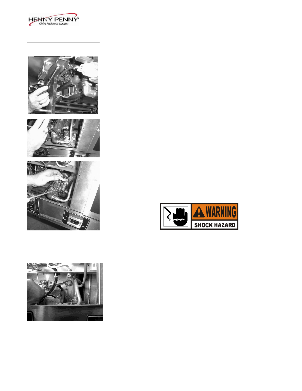
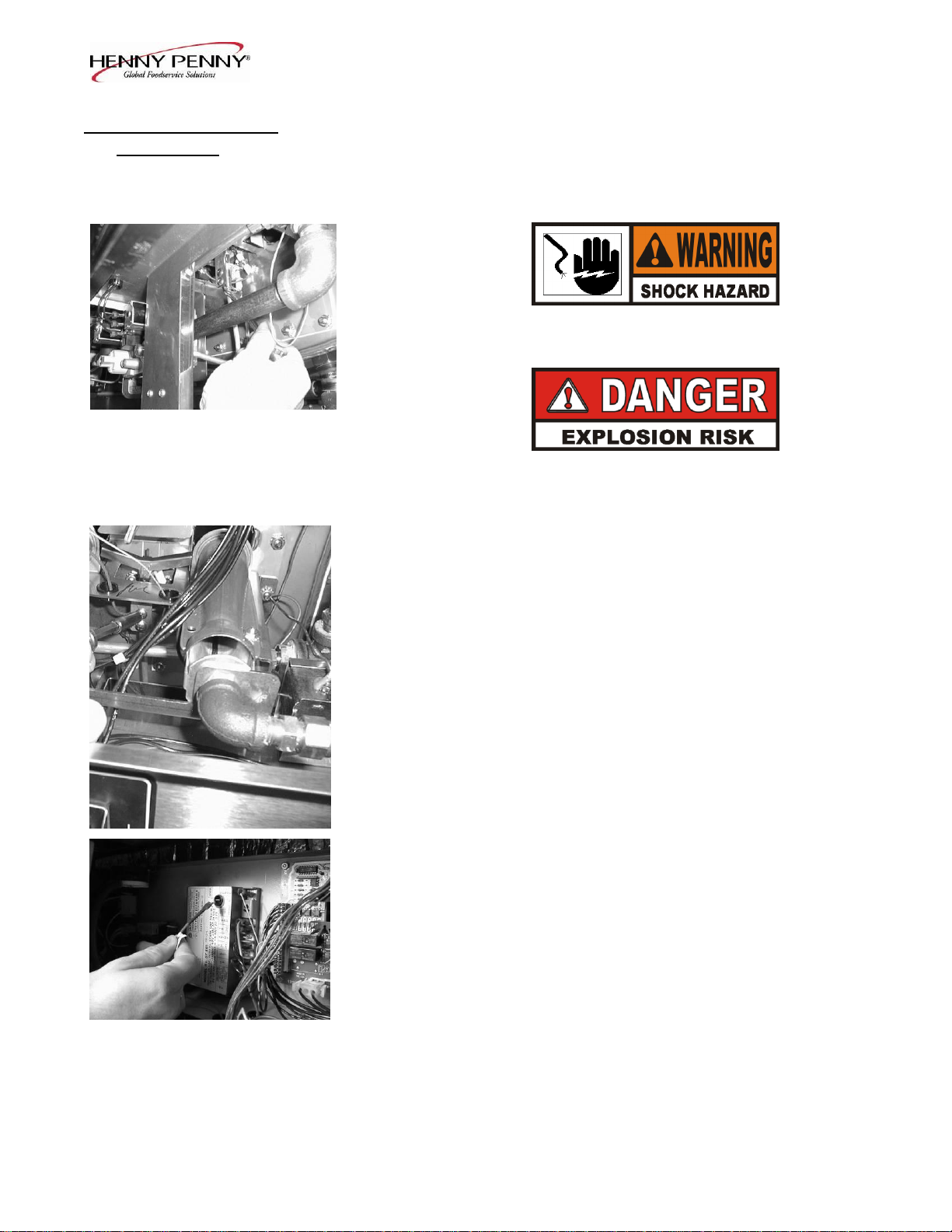
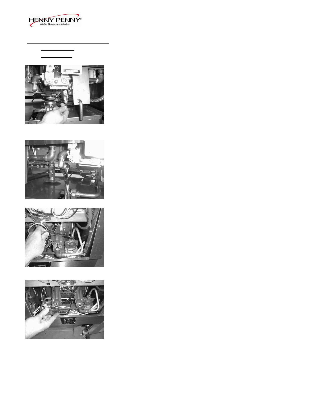
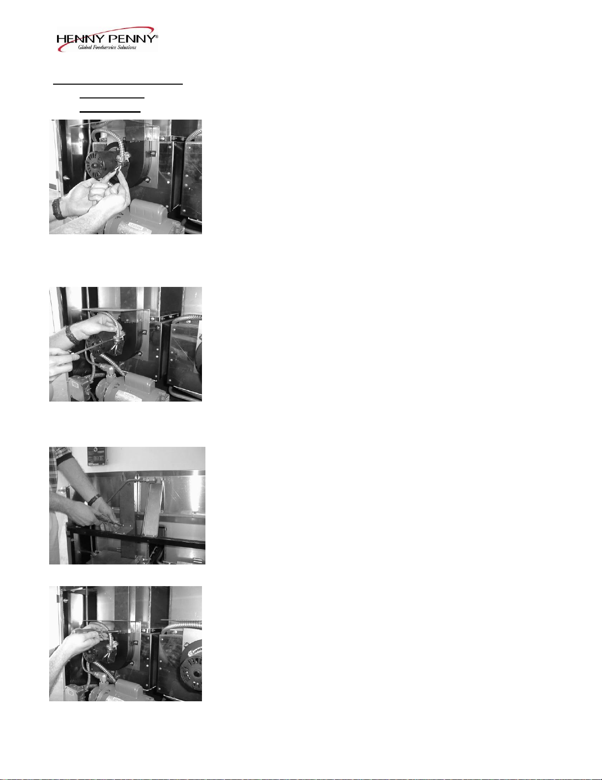
3. Using a 7/16 inch wrench, remove the pilot line from the gas
control valve.
4. Using a 1 inch wrench, loosen the nut securing the main gas
inlet line to the gas control valve.
5. Using 5/8 inch wrench, remove the two burner gas line fittings
at the black tee fitting, located behind the control panel area.
6. Using a Phillips head screwdriver, remove the three screws
securing the gas control valve bracket to the frame of the fryer
behind the control panel area.
203 2-15
Model OFE/OFG-321,322,323,324
2-16. GAS CONTROL VALVE
ASSEMBLY
(Continued)
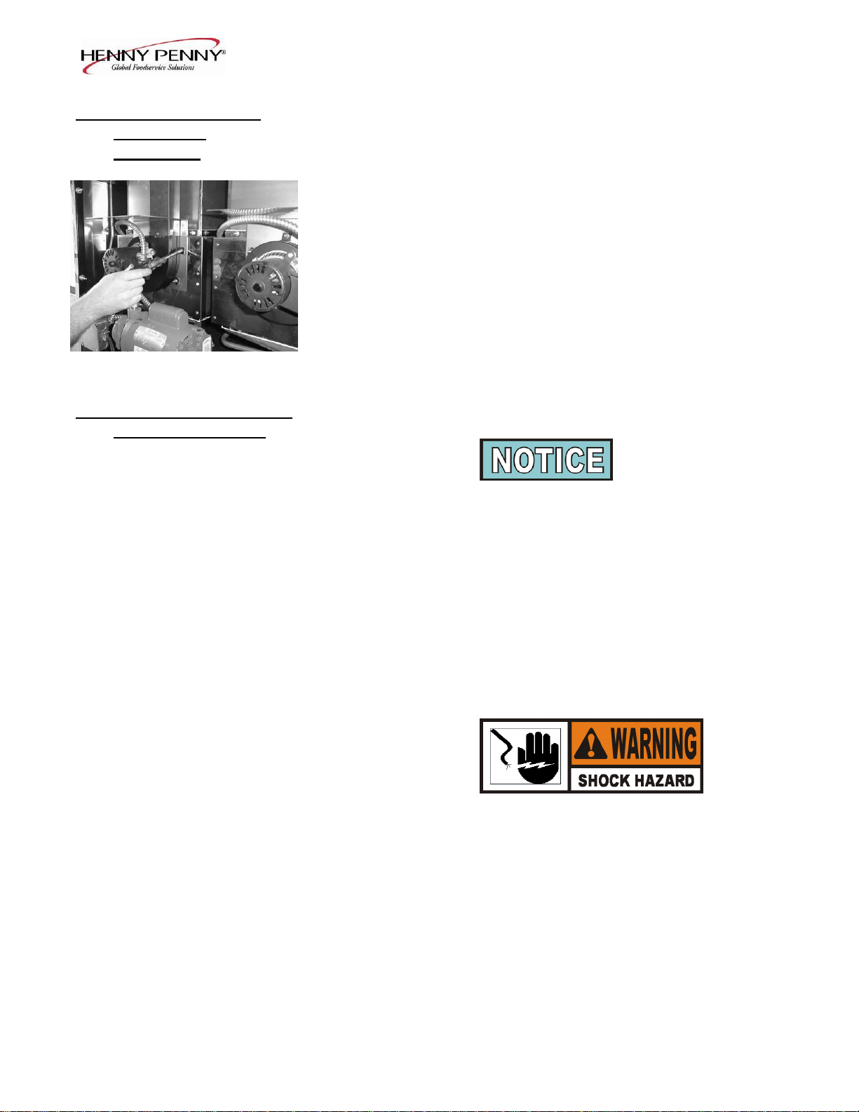
7. With the bracket dropped down, remove the two screws behind
the bracket securing the gas control valve to the bracket.
8. Install the new gas control valve in reverse order.
2-17. BLOWER MOTOR
ASSEMBLY The blower motor assembly induces the draft for the burners. If the
blower motor fails, the air switch will fail to close, causing an
“E-20B” error code in the display.
1. Remove electrical power supplied to the unit.
To avoid electrical shock or property damage, move the
POWER switch to OFF and disconnect main circuit
breaker, or unplug cord at wall receptacle.
2. Remove screws securing the two rear covers to the unit.
3. Remove the wire cover from the blower motor housing.
2-16 203
Model OFE/OFG-321,322,323,324
2-17. BLOWER MOTOR
ASSEMBLY
(Continued)
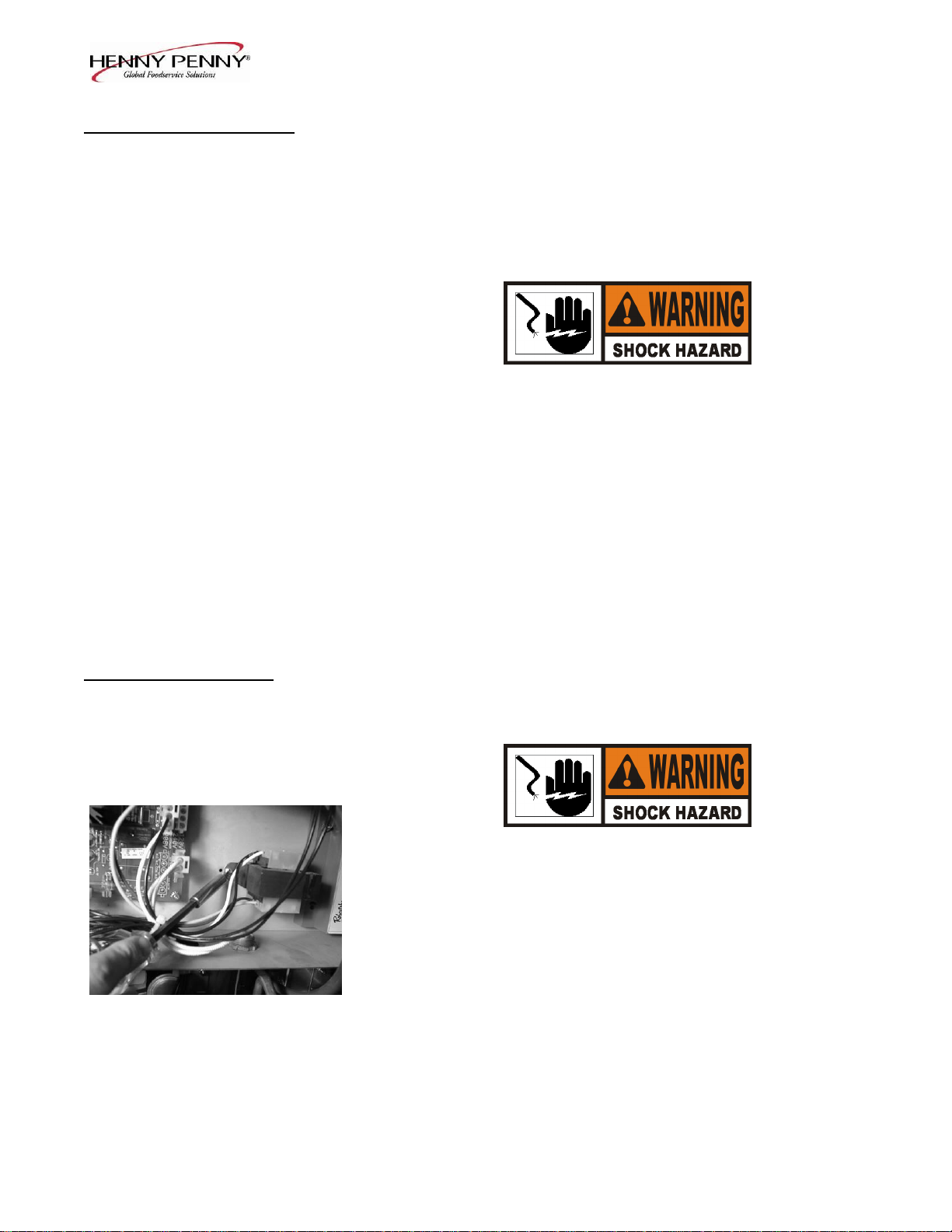
4. Remove wire nuts connecting blower motor wires to wires in
conduit.
5. Loosen conduit from blower motor.
6. Remove screws connecting flue to bracket in upper frame.
7. Remove screws connecting flue to blower.
203 2-17
Model OFE/OFG-321,322,323,324
2-17. BLOWER MOTOR
ASSEMBLY
(Continued)
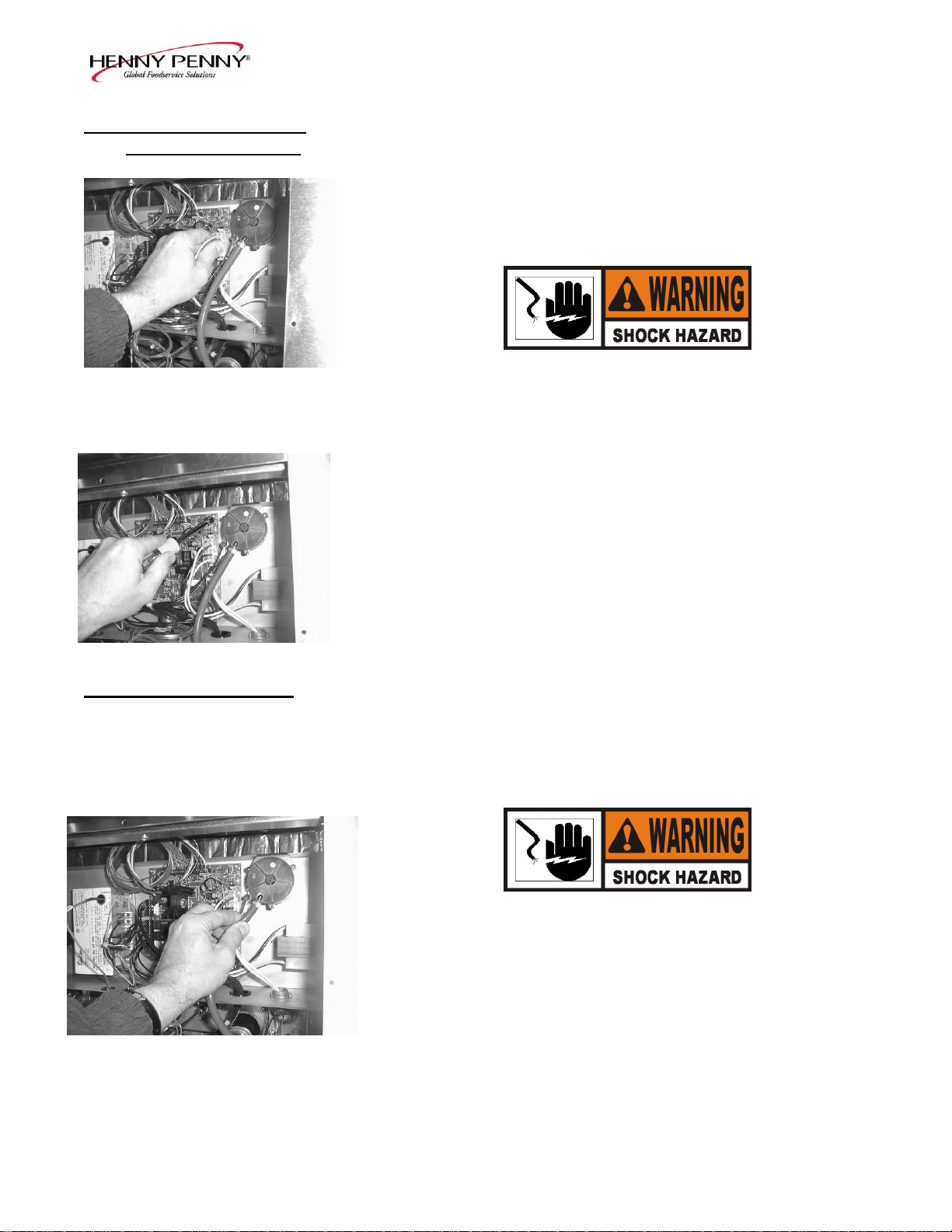
8. Using 3/8 inch nut driver, remove nuts securing blower to the
unit. Pull blower from unit.
9. Install new blower in reverse order.
2-18. HEATING ELEMENTS
(ELECTRIC ONLY)
Heating elements are available for 208 and 230 volts. Check
data plate to determine correct voltage.
Checkout:
If the shortenings temperature recovery is very slow or at a slower
rate than required, this may indicate defective heating element(s).
An ohmmeter will quickly indicate if the elements are shorted or
open.
1. Remove electrical power supplied to the frypot to be worked on.
To avoid electrical shock or property damage, move the
POWER switch to OFF and disconnect main circuit
breaker, or unplug cord at wall receptacle, to the frypot
to be worked on. Be aware the other controls will have
power.
2. Remove control panel.
2-18 203
Model OFE/OFG-321,322,323,324
2-18. HEATING ELEMENTS
(ELECTRIC ONLY)
(Continued) 3. Perform an ohm check on one element at a time, with wires
disconnected from element. If the resistance is not within
tolerance, replace the element.
Voltage Wattage Resistance Ohms (cold)
208 4800 9
230 4800 11
Replacement:
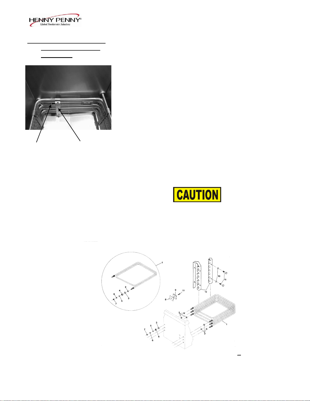
Refer to figure 2-2.
1. Drain the shortening from the frypot.
2. Remove the high limit bulb holder from the heating element
inside the frypot.
3. Remove the heating element wires from the terminals by
removing the nuts and washers. Label each so it can be
replaced on the new element in the same position.
4. Remove the bolts from the five element spreaders. The
element spreaders will now pull off the elements.
5. Remove the brass nuts and washers which secure the ends of
the elements through the frypot wall.
6. Remove the heating elements from the frypot as a group by
lifting the far end and sliding them up and out toward the
rear of the frypot.
Always install new rubber O-rings when installing heater
elements.
7. Install new heating elements with the new O-rings, terminal
end first at approximately a 45 angle, slipping the terminals
through the front wall of the frypot.
8. Replace the brass nuts and washers on the element terminals.
Tighten the brass nuts to 30 foot lbs. of torque.
203 2-19
Model OFE/OFG-321,322,323,324
2-18. HEATING ELEMENTS
(ELECTRIC ONLY)
(Continued) 9. Evenly space the element spreaders on the sides of the
elements and reinstall bolts. Place the fifth spreader in the
front of the elements as to protect the temperature probe.
(Fig.6-1
10. Replace the high limit bulb holder on the top element, and
position the bulb between the top and second element
midway from side to side, and tighten screw that holds the
bulb in place.
11. Reconnect the wires to the appropriate terminal as labeled
when they were removed.
Temperature Spreader
Probe
Fig. 2-1 12. Replace the front control panel.
13. Connect the power cord to the wall receptacle or close wall
circuit breaker.
Heating elements should never be energized without
shortening in the frypot, or damage to the elements could
result.
14. Replace the shortening in the frypot.
Fig. 2-2
2-20 203
33
37
Electromechanical
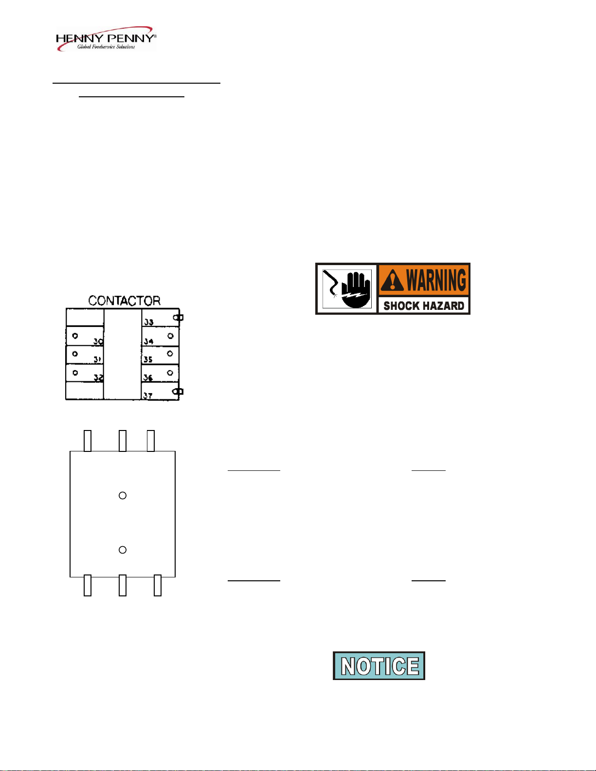
2-19. HEATING CONTACTORS
(ELECTRIC ONLY)
Each well of an electric fryer requires two switching contactors.
The first in line is the primary contactor and the second in line is
the heat contactor. When open, the primary contactor does not
allow power to flow to the heat contactor. When closed, the
primary supplies voltage to the heat contactor. When the heat
contactor is open, no voltage is supplied to the heating elements.
When the heat contactor closes, voltage is supplied to the heating
elements.
Checkout (Power Removed)
1. Remove electrical power supplied to the frypot to be worked on.
To avoid electrical shock or property damage, move the
POWER switch to OFF and disconnect main circuit
breaker, or unplug cord at wall receptacle, to the frypot
to be worked on. Be aware the other controls will have
power.
2. Remove the control panel.
30 31 32 3. Perform a check on the contactor as follows:
ELECTROMECHANICAL CONTACTOR
Test Points Results
From 30 to 34 open circuit
From 31 to 35 open circuit
From 32 to 36 open circuit
From 33 to 37 ohm reading 5 to 6
MERCURY CONTACTOR
Test Points Results
34 35 36 From 30 to 34 open circuit
Mercury Contactor From 31 to 35 open circuit
From 32 to 36 open circuit
From 33 to 37 ohm reading 1700
109 2-21
Wires should be removed and labeled to obtain an accurate check
of contactors.
Model OFE/OFG-321,322,323,324
 Loading...