

Page 1

Model OFE/OFG/OEA/OGA-341, 342
TECHNICAL MANUAL
Model OFE/OFG-341
Model OFE/OFG-342
Model OEA/OGA-341
Model OEA/OGA-342
High Volume Open Fryer
Henny Penny
Page 2

Model OFE/OFG/OEA/OGA-341, 342
Page 3
Model OFE/OFG/OEA/OGA-341, 342
This manual should be retained in a convenient location for future reference.
A wiring diagram for this appliance is located on the inside of the right side panel.
Post in a prominent location, instructions to be followed in event user smells gas. This information shall
be obtained by consulting the local gas supplier.
Do not obstruct the flow of combustion and ventilation air. Adequate clearance must be left all around
appliance for sufficient air to the combustion chamber.
The Model OFG/OGA-34X open fryer is equipped with a continuous pilot. But the open fryer can not be
operated without electric power. The unit will automatically return to normal operation when power is
restored.
To avoid a fire, keep appliance area free and clear from combustibles.
Improper installation, adjustment, alteration, service or maintenance can cause property damage,
injury or death. Read the installation, operating and maintenance instructions thoroughly before
installing or servicing this equipment.
FOR YOUR SAFETY, DO NOT STORE OR USE GASOLINE OR OTHER FLAMMABLE
VAPORS AND LIQUIDS IN THE VICINITY OF THIS OR ANY OTHER APPLIANCE.
FM06-030
Revised 12-30-09
Page 4

Model OFE/OFG/OEA/OGA-341, 342
TABLE OF CONTENTS
Section Page
Section 1. TROUBLESHOOTING ...................................................................................................1-1
1-1. Introduction .............................................................................................................1-1
1-2. Safety ......................................................................................................................1-1
1-3. Troubleshooting ......................................................................................................1-2
1-4. Error Codes .............................................................................................................1-4
Section 2. MAINTENANCE .............................................................................................................2-1
2-1. Introduction .............................................................................................................2-1
2-2. Maintenance Hints ..................................................................................................2-1
2-3. High Temperature Limit Control (Gas Units) ........................................................2-1
2-4. Complete Control Panel Replacement ...................................................................2-4
2-5. Power Switch ..........................................................................................................2-4
2-6. Temperature Probe Replacement (Gas) ..................................................................2-5
2-7. Temperature Probe Replacement (Electric) ............................................................2-6
2-8. Flame Sensor/Pilot/Ignitor Assembly (Gas) ...........................................................2-7
2-9. Ignition Module ......................................................................................................2-9
2-10. Transformer Replacement .......................................................................................2-10
2-11. Control & I/O Boards Replacement ........................................................................2-10
2-12. Vacuum Switch Replacement .................................................................................2-11
2-13. Drain Microswitch Replacement ............................................................................2-12
2-14. Filter Switch Replacement ......................................................................................2-12
2-15. Gas Control Valve Replacement .............................................................................2-13
2-16. Blower Motor Replacement ....................................................................................2-15
2-17. Heating Elements (Electric) ....................................................................................2-17
2-18. Heating Contactors (Electric) .................................................................................2-19
2-19. Speaker Assembly ...................................................................................................2-22
2-20. High Temperature Limit Control (Electric) ............................................................2-23
2-21. Filter Pump and Motor Removal ............................................................................2-26
2-22. Autolift Transformer Replacement (if applicable) .................................................2-27
2-23. Autolift PC Board Replacement (if applicable) ......................................................2-28
2-24. Autolift Actuator (Motor) Replacement (if applicable) ..........................................2-28
Wiring Diagrams
Section 3. PARTS INFORMATION .................................................................................................3-1
3-1. Introduction .............................................................................................................3-1
3-2. Genuine Parts ..........................................................................................................3-1
3-3. When Ordering Parts...............................................................................................3-1
3-4. Prices .......................................................................................................................3-1
3-5. Delivery ..................................................................................................................3-1
3-6. Warranty .................................................................................................................3-1
3-7. Recommended Spare Parts for Distributors ............................................................3-1
ii 106
Page 5
Model OFE/OFG/OEA/OGA-341, 342
SECTION 1. TROUBLESHOOTING
1-1. INTRODUCTION This section provides troubleshooting information in the form of
an easy to read table.
If a problem occurs during the first operation of a new fryer,
recheck the Installation Section of the Operator’s Manual.
Before troubleshooting, always recheck the Operation Section of
the Operator’s Manual.
1-2. SAFETY Where information is of particular importance or is safety related,
the words DANGER, WARNING, CAUTION, or NOTE are used.
Their usage is described on the next page:
SAFETY ALERT SYMBOL is used with DANGER,
WARNING or CAUTION which indicates a personal
injury type hazard.
NOTICE is used to highlight especially important
information.
CAUTION used without the safety alert symbol indicates a
potentially hazardous situation which, if not avoided, may
result in property damage.
CAUTION used with the safety alert symbol indicates a
potentially hazardous situation which, if not avoided,
could result in minor or moderate injury.
WARNING indicates a potentially hazardous situation
which, if not avoided, could result in death or serious
injury.
DANGER INDICATES AN IMMINENTLY
HAZARDOUS SITUATION WHICH, IF NOT
AVOIDED, WILL RESULT IN DEATH OR
1003 1-1
SERIOUS INJURY.
Page 6
Model OFE/OFG/OEA/OGA-341, 342
1-3. TROUBLESHOOTING To isolate a malfunction, proceed as follows:
1. Clearly define the problem or symptom and when it
occurs.
2. Locate the problem in the Troubleshooting table.
3. Review all possible causes, then one at a time work
through the list of corrections until the problem is solved.
If maintenance procedures are not followed correctly,
injuries and/or property damage could result.
PROBLEM CAUSE CORRECTION
With the switch in • Open circuit • Check to see if unit is plugged in
the ON position,
fryer is completely • Check breaker or fuse at supply box
inoperative
• Check power switch per Power Switch
Section; replace if defective
• Check voltage at wall receptacle
• Check cord and plug
Shortening will not • Faulty contactor • Check contactor per Heating Contactors
heat but lights are on (elec. model) Section
• Faulty gas control • Check gas control valve per Gas Control
valve (gas model) Valve Assembly Section
• Faulty temperature • Check temperature probe per Temperature
probe Probe Replacement Section; “E6”
• Faulty high limit • Check high limit per the appropriate High
Temperature Limit Control Section; “E10”
• Faulty drain switch • Check drain switch per Drain Microswitch
Section; “E15"
1-2 1003
Page 7

Model OFE/OFG/OEA/OGA-341, 342
1-3. TROUBLESHOOTING(Continued)
PROBLEM CAUSE CORRECTION
Heating of • Low or improper • Use a meter and check the receptacle
shortening too voltage (elec. unit) voltage against the data plate
slow
• Weak or burnt out • Check heating elements per Heating
elements (elec. unit) Elements Section
• Wire(s) loose • Tighten
• Burnt or charred • Replace wire and clean connectors
wire connection
• Faulty contactor • Check contactor per Heating Contactors
Section
• Supply line too small • Increase supply line size; refer to
- low gas volume (gas Installation Section of Operator’s Manual
unit)
• Improper ventilation • Refer to Installation Section of Operator’s
Manual
Shortening • Temperature probe • Calibrate temperature probe if ± 10° off;
overheating needs calibrated if more than ± 10° off, replace temperature
probe
• Mercury contactor • Check mercury contactor for not opening;
stuck closed replace if necessary (elec. unit)
• Bad control board • Replace control board if heat indicator stays
on past ready temperature
Foaming or boiling • Water in shortening • At end of cook cycle, drain shortening and
over of shortening clean
• Improper or bad • Use recommended shortening
shortening
• Improper filtering • Refer to the Filtering the Shortening
Section in Operator’s Manual
• Improper rinsing after • Clean and rinse the frypot; then dry
cleaning the fryer thoroughly
1003 1-3
Page 8

Model OFE/OFG/OEA/OGA-341, 342
1-2. TROUBLESHOOTING
(Continued)
PROBLEM CAUSE CORRECTION
Shortening will not • Drain valve clogged • Open valve, force cleaning brush through
drain from frypot with crumbs drain
• Drain valve will not • Replace cotter pins in valve coupling
open by turning
handle
Filter motor runs • Pump clogged • Remove pump cover and clean
but pumps shortening
slowly • Filter line connection • Tighten all filter line connections
loose
• Solidified shortening • Clear all filter lines of solidified shortening
in lines
Filter switch on, • Defective switch • Check/replace switch per Filter Switch
motor does not run Section
• Defective motor • Check/replace motor
• Motor thermal • Reset thermal switch on filter motor
protector tripped
Motor hums but • Clogged lines or • Remove and clean pump and lines
will not pump pump
• Replace pump seal, rotor and rollers
1-4 1003
Page 9
Model OFE/OFG/OEA/OGA-341, 342
1-4. ERROR CODES In the event of a control system failure, the digital display shows
An error message. These messages are coded: “E4”, “E5”, “E6”,
“E10”, “E15”, “E20”, “E31”, “E41”, “E46”, and “E92”. A
Constant tone is heard when an error code is displayed, and to
silence this tone, press any button.
DISPLAY CAUSE PANEL BOARD CORRECTION
“E4” Control board Turn switch to OFF position, then turn switch back to ON;
overheating if display shows “E4”, the control board is getting too hot;
check the louvers on each side of the unit for obstructions
“E5” Shortening Turn switch to OFF position, then turn switch back to ON;
overheating if display shows “E5”, the heating circuits and temperature
probe should be checked
“E6-A” Temperature Turn switch to OFF position, then turn switch back to ON;
probe open if display shows “E6” the temperature probe should be
checked
“E6-B” Temperature Turn switch to OFF position, then turn switch back to ON;
probe shorted if display shows “E6” the temperature probe should be
checked to replace, per Temperature Probe Replacement
Section
“E10” High limit Reset the high limit by manually pushing up on the red
reset button; if high limit does not reset, high limit must be
replaced per High Limit Temperature Control Section
“E15” Drain switch Close drain, using the drain valve handle; if display still
failure shows “E-15”, check the drain microswitch per Drain
Microswitch Section
“E31” Elements not Check to make sure the elements are hinged all way down
hinged all the into the frypot; check for obstructions under elements
way down
“E41”, Programming Turn switch to OFF, then back to ON; if display shows any
“E46” failure of the error codes, try to reinitialize the control (Special
Program Mode Section of Operator’s Manual); if error
code persists, replace the control panel per Complete
Control Panel Replacement Section
1003 1-5
Page 10

Model OFE/OFG/OEA/OGA-341, 342
1-4. ERROR CODES
(Continued)
DISPLAY CAUSE PANEL BOARD CORRECTION
“E-20 A” Vacuum Press the timer button to try the ignition process again,
switch failure and if “E-20 A” persists, check the air switch per Vacuum
(stuck closed) Switch Section
“E-20 B” Draft fan or Press the timer button to try the ignition process again,
vacuum and if “E-20 B” persists, check the vacuum switch per
switch failure Vacuum Switch Section or the blower motor per Blower
(stuck open) Motor Assembly Section
“E-20 C” Ignition modules Press the timer button to try the ignition process again; if
not responding “E-20 C” persists, check the ignition module per Ignitor
Module Section, the spark ignitor per Pilot/Ignitor
Assembly Section, or the I/O board per Control & I/O
Boards Section
“E-20 D” Pilots not lit or Press the timer button to try the ignition process again; if
no flame sense “E-20 D” persists, check the ignition module per Ignition
Module Section, the I/O board per Control & I/O Boards
Section, or the flame sensor per Flame Sensor Section
“E-47” Analog converter Turn switch to OFF, then back to ON; if “E47” persists,
chip or 12 volt replace the I/O board, or the PC board; if speaker
supply failure tones are quiet, probably I/O board failure
“E-48” Input system Replace PC board
error
“E-70” Faulty power Check power switch, along with its wiring;
switch or switch replace I/O board if necessary
wiring; faulty I/O
board
“E-92” 24 VAC fuse Check for shorted component in 24 volt circuit;
on I/O open (i.e., high limit, drain switch, vacuum switch)
1-6 1003
Page 11

Model OFE/OFG/OEA/OGA-341, 342
SECTION 2. MAINTENANCE
2-1. INTRODUCTION This section provides procedures for the check out and
replacement of the various parts used within the fryer. Before
replacing any parts refer to the Troubleshooting Section. It will aid
you in determining the cause of the malfunction.
2-2. MAINTENANCE HINTS 1. You may need to use a multimeter to check the electric
components.
2. When the manual refers to the circuit being closed, the
multimeter should read zero unless otherwise noted.
3. When the manual refers to the circuit being open, the
multimeter will read infinity.
2-3. HIGH TEMPERATURE
LIMIT CONTROL This high temperature control is a safety, manual reset control,
(Gas Units) which senses the temperature of the shortening. If the short-
ening temperature exceeds 425°F (218°C), this switch opens
and shuts off heat to the frypot. When the temperature of the
shortening drops to a safe operation limit, the control must be
manually reset by pressing the red reset button. The red reset
button is located under the control panel, in the front of the fryer.
(Figure 2-1). This allows heat to be supplied to the frypot.
Before replacing a high temperature limit control, check to see
that its circuit is closed.
Figure 2-1
The shortening temperature must be below 380°F (193°C)
to accurately perform this check.
Checkout
To avoid electrical shock or property damage, move the
power switch to OFF and disconnect main circuit
breaker, or unplug cord at wall receptacle.
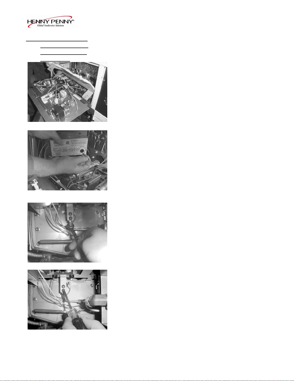
1. Remove the control panel. Figure 2-2.
Figure 2-2
1003 2-1
Page 12

Model OFE/OFG/OEA/OGA-341, 342
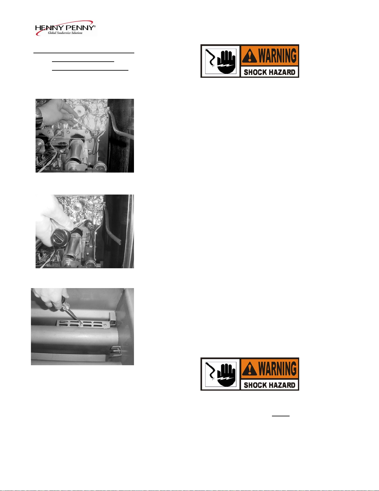
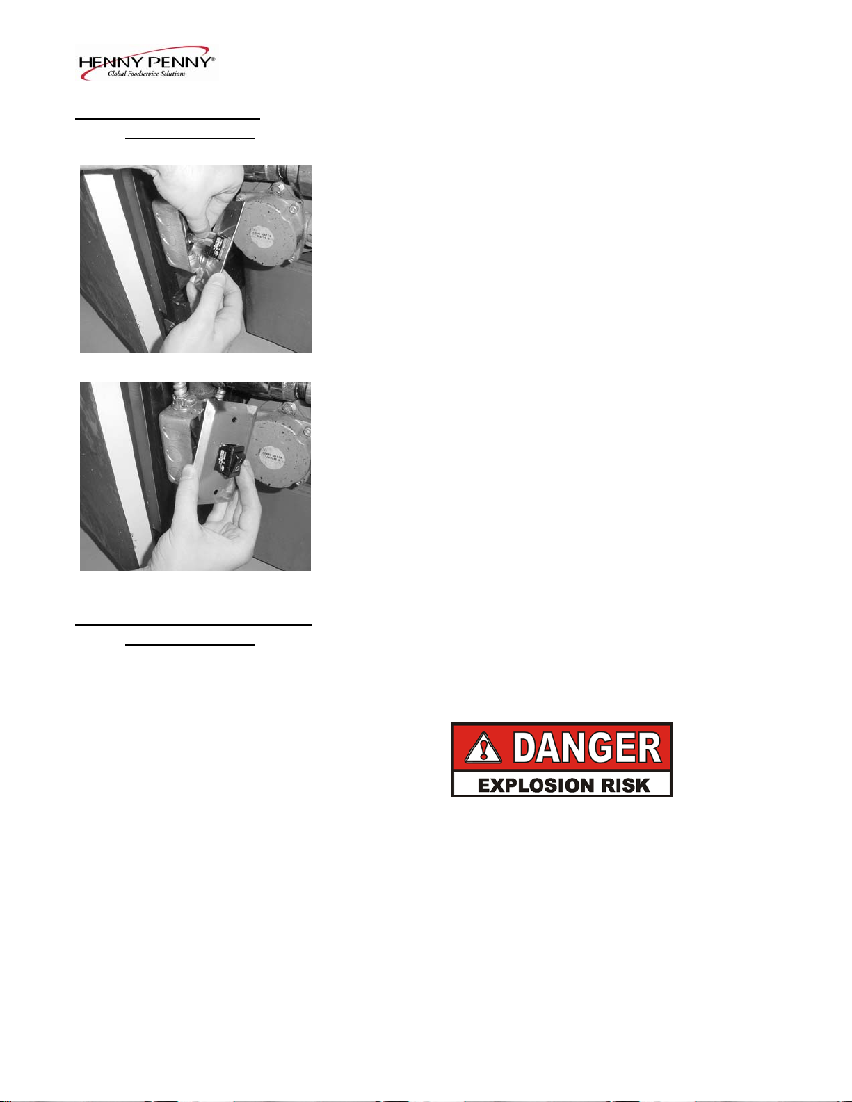
1-3. HIGH TEMPERATURE 2. Using a Phillip’s head screwdriver, remove the screws securing
LIMIT CONTROL the inner heat shield and remove from unit. Figure 2-3.
(Gas Units) (Continued)
Figure 2-3 3. Remove the screw securing the high limit bracket to the frame
and remove the high limit and bracket from unit. Figure 2-4.
Figure 2-4 4. Remove the two screws securing the high limit to the bracket
and remove the high limit from bracket.
5. Remove the two electrical wires from the high temperature
limit control. Figure 2-5.
Figure 2-5
6. Manually reset the control, then check for continuity between
the two terminals after resetting the control. If the circuit is
open, replace the control, then continue with this procedure.
(If the circuit is closed, the high limit is not defective. Re connect the two electrical wires.)
2-2 1003
Page 13
Model OFE/OFG/OEA/OGA-341, 342
2-3. HIGH TEMPERATURE
LIMIT CONTROL
(Gas Units) (Continued)
Replacement To avoid electrical shock or property damage, move the
power switch to OFF and disconnect main circuit
breaker, or unplug cord at wall receptacle.
1. If the tube is broken or cracked, the control opens, shutting
off electrical power to the heat circuit. The control cannot be
reset, and it continuously clicks when pushed.
2. Drain the shortening from the frypot and discard. A substance
from the tube could contaminate the shortening.
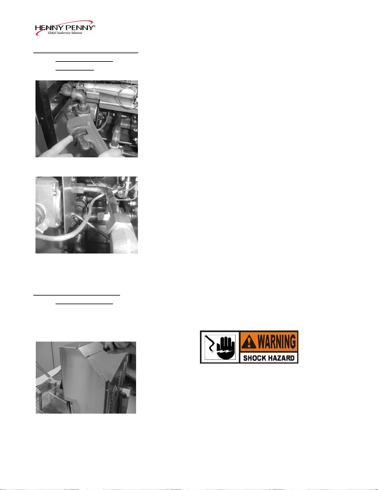
Figure 2-6 3. Remove the control panel.
4. Using a 5/16” wrench, loosen small inside screw nut on
capillary tube. Figure 2-6.
5. Using a 11/16” crows-foot, remove the larger nut securing the
capillary tube to the pot. Figure 2-7.
6. Remove the two screws securing the high limit guard and
Figure 2-7 remove guard. Figure 2-8
7. Straighten the capillary tube inside the frypot, and pull the
capillary tube through the frypot, from behind the control
panel. Remove the defective high limit from the control panel
area.
8. Replace new high limit in reverse order.
Figure 2-8
To avoid electrical shock or other injury, run the
capillary line under and away from all electrical power
wires and terminals. The tube must never
be in such a
position where it could accidentally touch the electrical
power terminals.
1003 2-3
Page 14

Model OFE/OFG/OEA/OGA-341, 342
2-4. COMPLETE CONTROL Should the control board become inoperative, follow these
PANEL REPLACEMENT instructions for replacing the board.
1. Remove electrical power supplied to the unit.
To avoid electrical shock or property damage, move the
power switch to OFF and disconnect main circuit
breaker, or unplug cord at wall receptacle.
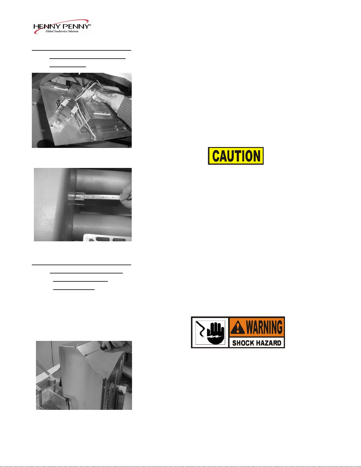
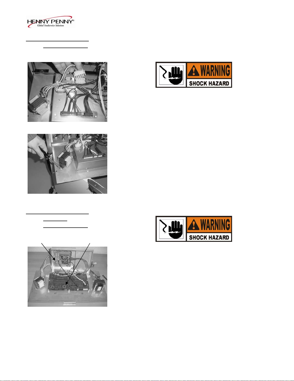
2. Remove the two screws securing the control panel and lift out.
Figure 2-9 Figure 2-9.
3. Unplug the wire connectors going to the control panel.
Figure 2-10.
4. Remove transformer(s) from control panel. They must be
installed on the replacement panels.
5. Install new control panel in reverse order.
When plugging connectors onto new control panel, be sure the
connectors are inserted onto all of the pins, and that the
connectors are not forced onto the pins backwards. If not
Figure 2-10 connected properly, damage to the board could result.
2-5. POWER SWITCH 1. Remove electrical power supplied to fryer.
To avoid electrical shock or property damage, move the
power switch to OFF and disconnect main circuit
breaker, or unplug cord at wall receptacle.
2. Remove control panel.
3. Label and remove wires from the switch. With test instrument
Figure 2-11 check across the terminals of the switch with switch in the on
position, and the circuit should be closed. In the off position,
the circuit should be open. If the switch checks defective,
replace by continuing with this procedure. Figure 2-11.
2-4 504
Page 15
Model OFE/OFG/OEA/OGA-341, 342
2-5. POWER SWITCH (Continued)
4. With control panel removed, and the wires off the switch, push
in on tabs on the switch to remove from panel. Figure 2-12.
5. Replace with new switch, and reconnect wires to switch.
6. Replace the control panel.
Figure 2-12
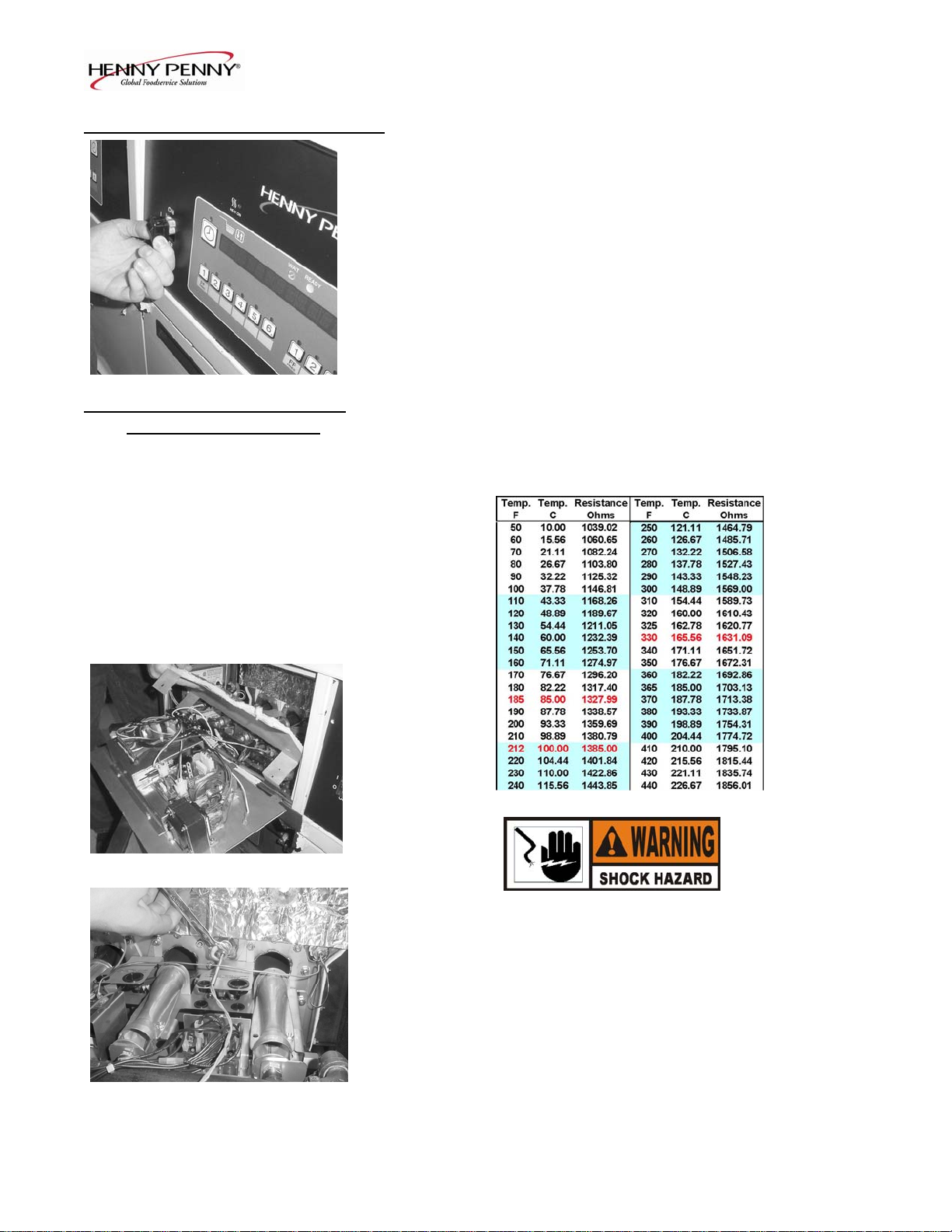
2-6. TEMPERATURE PROBE The temperature probe relays the actual shortening temperature
REPLACEMENT (Gas) to the control board. If it becomes disabled, “E06” shows in the
display. Also, if the shortening temperature is out of calibration
more than 10°F or C°, the probe should be replaced. An Ohm check
can be performed also. See chart below.
1. Remove electrical power supplied to the fryer.
Figure 2-13
To avoid electrical shock or property damage, move the
power switch to OFF and disconnect main circuit
breaker, or unplug cord at wall receptacle.
2. Drain the shortening from the frypot.
3. Remove the control panel and heat shield from control area.
Figure 2-13.
4. Using a ½ inch wrench, remove the nut on the compression
Figure 2-14 fitting. Figure 2-14.
806 2-5
Page 16
Model OFE/OFG/OEA/OGA-341, 342
2-6. TEMPERATURE PROBE 5. Remove the probe from the frypot, and disconnect wire
REPLACEMENT (GAS) connector from the control panel. Figure 2-15.
(Continued)
6. Place the nut and new ferrule on the new probe and insert the
probe into the compression fitting until it extends one (1) inch
(2.54cm) into the frypot. Figure 2-16.
7. Tighten hand tight and then a half turn with wrench.
Figure 2-15
Excess force will damage probe.
8. Connect new probe to PC board and replace control panel.
9. Replace shortening, and turn power on to check out fryer.
Figure 2-16
2-7. TEMPERATURE PROBE The temperature probe relays the actual shortening temperature
REPLACEMENT (Gas) to the control board. If it becomes disabled, “E06” shows in the
REPLACEMENT display. Also, if the shortening temperature is out of calibration
(ELECTRIC) more than 10°F or C°, the probe should be replaced. An Ohm check
can also be performed. See chart on page 2-5.
1. Remove electrical power supplied to the fryer.
To avoid electrical shock or property damage, move the
power switch to OFF and disconnect main circuit
breaker, or unplug cord at wall receptacle.
2. Drain the shortening from the frypot.
Figure 2-17 3. Remove screws securing rear cover of fryer, and remove rear
cover. Figure 2-17.
2-6 1209
Page 17
Model OFE/OFG/OEA/OGA-341, 342
2-7. TEMPERATURE PROBE 4. Using a ½ inch wrench, remove the nut on the compression
REPLACEMENT fitting. Figure 2-18.
(ELECTRIC) (Continued)
5. Remove the probe from the frypot, and disconnect probe.
6. Place the nut and new ferrule on the new probe and insert the
probe into the compression fitting until it extends one (1) inch
(2.54cm) into the frypot.
7. Reconnect new probe onto wires, replace rear cover, and fryer
Figure 2-18 is now ready for use.
2-8. FLAME SENSOR/ The Henny Penny open fryer (gas) has electronic spark ignition
PILOT / IGNITOR that lights a standing pilot. The gap between the spark electrode
ASSEMBLY (GAS) and the pilot hood should be1/8 of an inch (3.18 mm). The
flame sensor recognizes the pilot flame and allows gas to continue
to the pilot. The flame sensor must send a minimum of two (2)
micro amps to the ignition module. The pilot flame should be split
in two by the flame sensor, causing the flame sensor to be bright
red in color.
1. Remove electrical power supplied to the unit.
To avoid electrical shock or property damage, move the
power switch to OFF and disconnect main circuit
breaker, or unplug cord at wall receptacle.
TO AVOID PERSONAL INJURY OR PROPERTY
DAMAGE, BEFORE STARTING THIS
PROCEDURE, MOVE THE MAIN POWER SWITCH
TO THE OFF POSITION. DISCONNECT THE MAIN
CIRCUIT BREAKERS AT THE CIRCUIT BREAKER
BOX OR UNPLUG SERVICE CORD FROM WALL
RECEPTACLE. TURN OFF THE MAIN GAS
SUPPLY TO THE FRYER AND DISCONNECT AND
CAP THE MAIN SUPPLY LINE TO FRYER, OR
POSSIBLE EXPLOSION COULD RESULT.
1003 2-7
Page 18
Model OFE/OFG/OEA/OGA-341, 342
2-8. FLAME SENSOR/
PILOT / IGNITOR
ASSEMBLY (Gas)
(Continued)
2. Remove the control panel and heat shield from control area.
Figure 2-19.
Figure 2-19
3. Disconnect the flame sense wire from ignition module.
Figure 2-20.
Figure 2-20
4. Using a 7/16” wrench, loosen the nut on the pilot tube and pull
tube from assembly. Figure 2-21.
Figure 2-21
5. Remove the two screws securing the assembly and pull
assembly from unit. Figure 2-22.
6. Now the flame sensor or or pilot assembly can be removed
from bracket.
Figure 2-22
2-8 1003
Page 19

Model OFE/OFG/OEA/OGA-341, 342
2-9. IGNITION MODULE During normal operation, the ignition modules send 24 volts to the
ignitors and gas valve. If a module does not sense a pilot flame,
the module starts the ignition process again. But, if a pilot light
goes out for longer that 10 seconds, or it goes out 3 times within 10
seconds, the module keeps the 24 volts from reaching the gas
valve. The burners shut down.
1. Remove electrical power supplied to the unit.
To avoid electrical shock or property damage, move the
power switch to OFF and disconnect main circuit
breaker, or unplug cord at wall receptacle.
Figure 2-23 2. Remove the control panel and heat shield from control area.
Figure 2-23.
3. Using a 3/8 inch socket, remove the two nuts securing the
module. Figure 2-24.
Figure 2-24
4. Label and remove the wires at module. Figure 2-25.
5. Install new module in reverse order.
Figure 2-25
1003 2-9
Page 20
Model OFE/OFG/OEA/OGA-341, 342
2-10. TRANSFORMER The transformer reduces voltage down (to 24V) to accommodate
REPLACEMENT those components with low voltage.
1. Remove electrical power supplied to the unit.
To avoid electrical shock or property damage, move the
power switch to OFF and disconnect main circuit
breaker, or unplug cord at wall receptacle.
2. Remove the control panel
Figure 2-26
3. Remove the two wire connectors to disconnect transformer
From panel. Figure 2-26.
4. Using a 3/8” nut-driver, remove the two nuts securing the
transformer to the panel and remove transformer. Figure 2-27.
5. Install the new transformer in reverse order.
Figure 2-27
2-11. CONTROL & I/O 1. Remove electrical power supplied to the unit.
BOARDS
REPLACEMENT
I/O Power Supply Control
To avoid electrical shock or property damage, move the
power switch to OFF and disconnect main circuit
breaker, or unplug cord at wall receptacle.
2. Remove the control.
3. Using a 5/16” nut-driver or wrench, remove the 4 nuts securing
the PC shield and remove shield. Figure 2-28.
4. Disconnect the wire assemblies from the appropriate board.
Figure 2-28
5. Using a 5/16” nut-driver or wrench, remove the 4 nuts securing
the appropriate board to the shroud.
6. Install the new board in reverse order.
2-10 1003
Page 21
Model OFE/OFG/OEA/OGA-341, 342
2-12. VACUUM SWITCH This switch senses the airflow from the induction blower. If
REPLACEMENT the airflow is reduced below a set amount, the switch opens and
the I/O board cuts power to the gas control valve, which shuts the
pilot flame off.
1. Remove electrical power supplied to the unit.
To avoid electrical shock or property damage, move the
power switch to OFF and disconnect main circuit
Figure 2-29 breaker, or unplug cord at wall receptacle.
2. Remove the control panel.
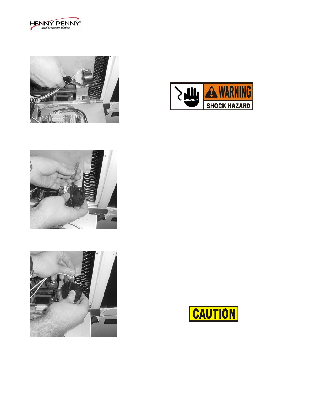
3. Remove the 2 screws securing the switch to the heat shield.
Figure 2-29.
4. Remove the air hose from the air switch. Figure 2-30.
Figure 2-30
5. Label and remove wires from air switch. Figure 2-31.
6. Install new vacuum switch in reverse order.
To avoid property damage, do not tamper with, or disas semble
this component. It is set and sealed from the factory and is not
Figure 2-31 to be adjusted.
1003 2-11
Page 22
Model OFE/OFG/OEA/OGA-341, 342
2-13. DRAIN MICROSWITCH Upon turning the drain handle, the drain microswitch should
REPLACEMENT “open”, cutting off the pilot flame. This will prevent the fryer
from heating while shortening is being drained from the frypot.
1. Remove electrical power supplied to the unit.
To avoid electrical shock or property damage, move the
power switch to OFF and disconnect main circuit
breaker, or unplug cord at wall receptacle.
2. The following check should be made to determine if the drain
microswitch is defective.
a. Remove the two screws and nuts securing the microswitch
Figure 2-32 to the drain rod valve bracket, and remove microswitch.
Figure 2-32.
b. Remove wires from the switch. Figure 2-33.
c. Check for continuity across the two outside terminals of the
drain switch. If the circuit is open, the drain switch is
defective. The circuit opens by pressing on the actuator of
the microswitch.
3. If defective, replace switch in reverse order.
Figure 2-33
2-14. FILTER SWITCH
REPLACEMENT
1. Remove electrical power supplied to the unit.
To avoid electrical shock or property damage, move the
power switch to OFF and disconnect main circuit
breaker, or unplug cord at wall receptacle.
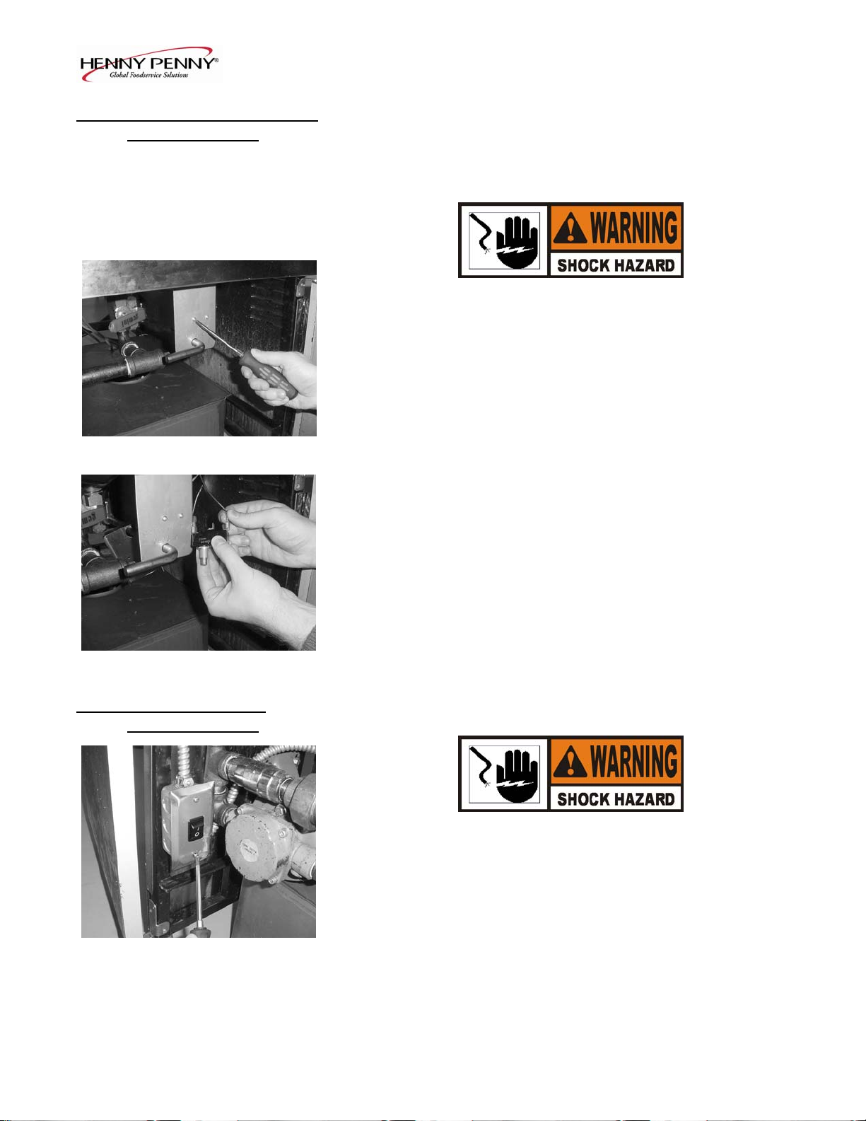
2. Open the door (left door on 2 well units), and remove the 2
Figure 2-34 screws securing the switch box cover. Figure 2-34.
2-12 1003
Page 23
Model OFE/OFG/OEA/OGA-341, 342
2-14. FILTER SWITCH 3. Label and remove the wires from the switch. With test
REPLACEMENT instrument check across the terminals of the switch. With the
(Continued) switch in the on position, the circuit should be closed. With the
switch in the off position, the circuit should be open. If the
switch is defective, replace by continuing with this
procedure. Figure 2-35.
Figure 2-35
4. With wires removed from the switch, push in on tabs on the
switch and remove switch from front of switch box cover.
Figure 2-36.
5. Push new switch into panel and reconnect wires.
Figure 2-36
2-15. GAS CONTROL VALVE The gas valve assembly controls the flow of gas to the pilot and the
REPLACEMENT main burner. The valve has two 24-volt coils, which are regulated
by the P and M terminals on the valve. The C terminal is the
common terminal. For gas flow to the pilot, 24 VAC must be
present between the P and C terminals. For gas flow to the main
burner, 24 VAC must be present between the M and C terminals.
TO AVOID PERSONAL INJURY OR PROPERTY
DAMAGE, BEFORE STARTING THIS
PROCEDURE, MOVE THE MAIN POWER SWITCH
TO THE OFF POSITION. DISCONNECT THE MAIN
CIRCUIT BREAKERS AT THE CIRCUIT BREAKER
BOX OR UNPLUG SERVICE CORD FROM WALL
RECEPTACLE. TURN OFF THE MAIN GAS
SUPPLY TO THE FRYER AND DISCONNECT AND
CAP THE MAIN SUPPLY LINE TO FRYER, OR
POSSIBLE EXPLOSION COULD RESULT.
1003 2-13
Page 24

Model OFE/OFG/OEA/OGA-341, 342
2-15. GAS CONTROL VALVE
REPLACEMENT
(Continued)
1. Remove right side panel. Figure 2-37.
Figure 2-37
2. Label and remove wires from gas valve. Figure 2-38
Figure 2-38
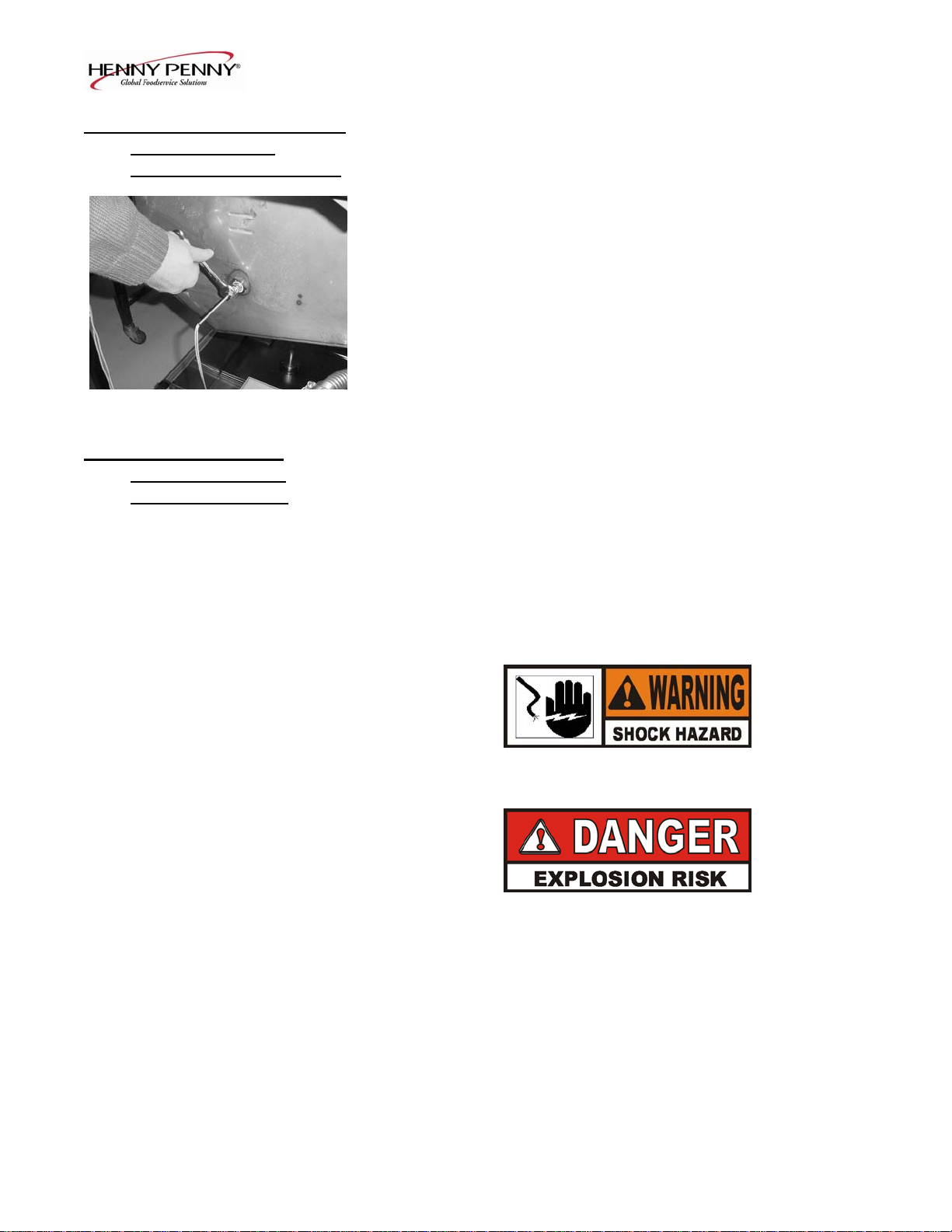
3. Using a 7/16 wrench, remove the pilot line from the gas valve.
Figure 2-39.
Figure 2-39
4. Using a 1-inch wrench, loosen the nut securing the main gas
inlet line to the gas valve. Figure 2-40.
Figure 2-40
2-14 1003
Page 25
Model OFE/OFG/OEA/OGA-341, 342
2-15. GAS CONTROL VALVE
REPLACEMENT
(Continued)
5. Using a pipe wrench, loosen the outlet fitting to the burner.
Figure 2-41.
Figure 2-41
6. Using a Phillips screwdriver, remove the 2 screws securing
the gas valve to the bracket and remove gas valve from unit.
Figure 2-42.
7. Remove the fittings from the gas valve and install in new gas
valve.
Figure 2-42
8. Install the new gas valve in reverse order.
2-16. BLOWER MOTOR The blower motor assembly induces the draft for the burners. If the
REPLACEMENT blower motor fails, the air switch will fail to close, causing an
“E-20B” error code in the display.
1. Remove electrical power supplied to the unit.
To avoid electrical shock or property damage, move the
power switch to OFF and disconnect main circuit
breaker, or unplug cord at wall receptacle.
2. Remove screws securing the rear cover to the unit.
Figure 2-43 Figure 2-43.
106 2-15
Page 26

Model OFE/OFG/OEA/OGA-341, 342
2-16. BLOWER MOTOR
REPLACEMENT
(Continued)
3. Remove the wire cover from the blower motor housing.
Figure 2-44.
Figure 2-44
4. Remove wire nuts connecting blower motor wires to wires in
conduit. Figure 2-45.
Figure 2-45
5. Loosen conduit from blower motor. Figure 2-46.
Figure 2-46
7. Remove screws connecting flue to blower. Figure 2-47.
Figure 2-47
2-16 1003
Page 27

Model OFE/OFG/OEA/OGA-341, 342
2-16. BLOWER MOTOR
REPLACEMENT
(Continued)
8. Using 3/8 inch nut driver, remove nuts securing blower to the
unit. Figure 2-48. Pull blower from unit.
Figure 2-48 9. Install new blower in reverse order.
2-17. HEATING ELEMENTS
(ELECTRIC)
Heating elements are available for 208 and 230 voltage. Check
data plate to determine correct voltage.
Checkout If the shortening temperature recovery is very slow or at a slower
rate than required, this may indicate defective heating element(s).
An ohmmeter quickly indicates if the elements are shorted or open.
1. Remove electrical power supplied to the frypot to be checked
To avoid electrical shock or property damage, move the
power switch to OFF and disconnect main circuit
breaker, or unplug cord at wall receptacle, to the frypot
to be worked on. Be aware the other control on 2-frypot
Figure 2-49 units will have power.
2. Remove rear cover. Figure 2-49.
3. Using a flat-head screwdriver, remove the appropriate wires
from the terminal blocks. Figure 2-50.
Figure 2-50
106 2-17
Page 28

Model OFE/OFG/OEA/OGA-341, 342
2-17. HEATING ELEMENTS 4. Perform an ohm check on one element at a time, with wires
(ELECTRIC) disconnected. The 2 elements actually have 3 small heating
(Continued) elements inside the outer plate. It’s important to check
between the correct wires to obtain an accurate ohm reading.
The wires are labeled for your convenience. If the resistance
is not within tolerance, replace the element.
Wire Nos. Voltage Wattage Ohms (cold)
1L1 to 1L1 208 11000 11.7
1L2 to 1L2 208 11000 11.7
1L3 to 1L3 208 11000 11.7
1L1 to 1L1 240 11000 15.7
1L2 to 1L2 240 11000 15.7
1L3 to 1L3 240 11000 15.7
Replacement 1. Drain the shortening from the frypot
2. Remove the high limit bulb holder from the heating
element inside the frypot. See High Limit Temperature
Control-Electric Section.
3. Using a Phillip’s-head screwdriver, remove the screws
securing the element to the element hinges. Figure 2-51.
4. Pull element from fryer and replace with new element,
following steps in reverse order.
5
. Connect the power cord to the wall receptacle or close wall
Figure 2-51 circuit breaker.
Heating elements should never be energized without
shortening in the frypot, or damage to the elements could
result.
6. Replace the shortening in the frypot, and unit is ready for
operation.
2-18
1003
Page 29

Model OFE/OFG/OEA/OGA-341, 342
2-18. HEATING Each well of an electric fryer requires two switching contactors.
CONTACTORS The first in line is the primary contactor and the second in line is
(ELECTRIC) the heat contactor. When open, the primary contactor does not
allow power to flow to the heat contactor. When closed, the
primary supplies voltage to the heat contactor. When the heat
contactor is open, no voltage is supplied to the heating elements.
When the heat contactor closes, voltage is supplied to the heating
elements.
Checkout (Power Removed) 1. Remove electrical power supplied to frypot to be worked on.
To avoid electrical shock or property damage, move the
power switch to OFF and disconnect main circuit
breaker, or unplug cord at wall receptacle, to the frypot
to be worked on. Be aware the other control on 2-frypot
Heat Contactor units will have power.
(Mercury)
2. Remove the control panel.
30 31 32
3. Perform a check on the contactor as follows:
From 23 to 29 open circuit
From 24 to 28 open circuit
From 25 to 27 open circuit
33
37
Test Points Results
From 30 to 34 open circuit
From 31 to 35 open circuit
From 32 to 36 open circuit
34 35 36 From 33 to 37 ohm reading 1700
Figure 2-52 From 22 to 26 ohm reading 415
Wires should be removed and labeled to obtain an accurate
check of contactors.
Figure 2-53
1003 2-19
Page 30

Model OFE/OFG/OEA/OGA-341, 342
2-18. HEATING
CONTACTORS
(ELECTRIC)
(Continued)
To avoid electrical shock, make connections before
applying power, take reading, and remove power before
removing meter leads. The following checks are
performed with the wall circuit breaker closed and the
main power switch in the ON position.
1. Re-apply power to unit and turn power switch to ON.
2. Using illustrations from previous page, check voltage as
follows:
Test Points Results
Heat Contactor
From terminal 34 to 35 The voltage should read
From terminal 35 to 36 the same at each terminal
From terminal 34 to 36
Test Points
Primary Contactor
From terminal 27 to 28 It should correspond to the
From terminal 28 to 29 voltage stated on the data
From terminal 27 to 29 plate.
Replacement If neither contactor is defective it must be replaced as follows:
(Heat Contactor)
To avoid electrical shock or property damage, move the
power switch to OFF and disconnect main circuit
breaker, or unplug cord at wall receptacle, to the frypot
to be worked on. Be aware the other control on 2-frypot
units will have power.
1. Remove only the wires directly connected to the contactor
Figure 2-54 being replaced. Label the wires for replacement. Figure 2-54.
2-20 1003
Page 31

Model OFE/OFG/OEA/OGA-341, 342
2-18. HEATING
CONTACTORS
(ELECTRIC)
Continued)
2. Remove the screws securing the contactor to the shroud, and
remove contactor. Figure 2-55.
3. Install new contactor, and see steps 4 and 5.
Figure 2-55
Replacement
(Primary Contactor)
1. Remove only the wires directly connected to the contactor
being replaced. Label the wires for replacement. Figure 2-56.
2. Remove screws securing contactor to unit and remove
contactor. Figure 2-57.
Figure 2-56
3. Install new contactor.
4. Reinstall the control panel.
1003 2-21
Figure 2-57
5. Reconnect power to the fryer and test for proper operation.
Page 32

Model OFE/OFG/OEA/OGA-341, 342
2-19. SPEAKER ASSEMBLY The speaker assembly emits audible signals to let the operator
know when cooking and hold times are finished.
1. Remove electrical power supplied to unit.
To avoid electrical shock or property damage, move the
power switch to OFF and disconnect main circuit
Figure 2-58 breaker, or unplug cord at wall receptacle.
2. Remove control panel.
3. Pull the power switch connector from back of panel.
Figure 2-58.
Figure 2-59
4. Pull the transformer connectors from back of panel.
Figure 2-59.
Figure 2-60 5. Using a 5/16” nutdriver or wrench, remove the 4 nuts securing
the PC board shield and pull shield from studs. Figure 2-60.
6. Pull the speaker connector from control board. Figure 2-61.
Figure 2-61
7. Using a 5/16” nut-driver or wrench, remove the 2 nuts securing
the speaker to the shield and remove speaker from panel.
Figure 2-62
8. Install new speaker in reverse order.
Figure 2-62
2-22 1003
Page 33

Model OFE/OFG/OEA/OGA-341, 342
2-20. HIGH TEMPERATURE This high temperature control is a safety, manual reset control,
LIMIT CONTROL which senses the temperature of the shortening. If the short (ELECTRIC) ening temperature exceeds 425°F (218°C), this switch opens
and shuts off heat to the frypot, and E10 shows in control display.
When the temperature of the shortening drops to a safe operation
reset the high limit by pressing the reset button. The reset
button is located behind the frypot, in the element hinge. A small
instrument, such as a Phillip’s head screwdriver, or Allen wrench
must be used to reset the high limit. This allows heat to be
supplied to the frypot once again. See Figure 2-63.
Before replacing a high temperature limit control, check to see
that its circuit is closed.
Figure 2-63
The shortening temperature must be below 380°F (193°C)
to accurately perform this check.
1. Remove electrical power supplied to fryer.
Checkout To avoid electrical shock or property damage, move the
power switch to OFF and disconnect main circuit
breaker, or unplug cord at wall receptacle.
2. Remove rear cover of fryer. Figure 2-64.
Figure 2-64
3. Remove the two screws securing the high limit to the bracket
and pull high limit from bracket. Figure 2-65.
Figure 2-65
106 2-23
Page 34

Model OFE/OFG/OEA/OGA-341, 342
2-20. HIGH TEMPERATURE
LIMIT CONTROL
(ELECTRIC)
(Continued)
4. Pull back cardboard cover and remove the two electrical wires
from the high temperature limit control. Figure 2-66.
Figure 2-66 5. Manually reset the control, then check for continuity between
the two terminals after resetting the control. If the circuit is
open, replace the control, then continue with this procedure.
(If the circuit is closed, the high limit is not defective. Re connect the two electrical wires.)
Replacement
To avoid electrical shock or property damage, move the
power switch to OFF and disconnect main circuit
breaker, or unplug cord at wall receptacle, to the frypot
to be worked on. Be aware the other control on 2-frypot
units will have power.
1. Drain the shortening from the frypot.
Figure 2-67
2. Remove capillary from brackets on upper part of element.
Figure 2-67.
3. Remove capillary bulb from bulb holder inside the frypot.
Figure 2-68
2-24 1003
Page 35

Model OFE/OFG/OEA/OGA-341, 342
2-20. HIGH TEMPERATURE
LIMIT CONTROL
(ELECTRIC)
(Continued)
4. Straighten the capillary tube, and pull capillary tube through
the hole in the element hinge, from the rear of the fryer.
5. Remove the defective control from the fryer.
Figure 2-69 6. Straighten the capillary tube on the new high limit, and thread
the capillary tube through the hole in the element hinge.
Figure 2-69.
7. Reattach the capillary to the brackets on the upper and lower
parts of the elements.
DO NOT crimp or kink the capillary tube during installation.
Also, keep capillary tube behind element to protect from
damage from the basket or during cleaning. Damage to the
capillary tube reduces the life of the high limit, or causes the
high limit to fail.
8. Connect wires to new high limit body and fasten to bracket,
using the two screws removed in the checkout part of this
section.
Make sure red reset button of high limit lines up with the
plunger that inserts into the element hinge.
To avoid electrical shock or other injury, run the capillary
line under and away from all electrical power wires and
terminals. The tube must never be in such a position
where it could accidentally touch the electrical power
terminals
9. Re-install the rear cover and unit is now ready for use.
1003 2-25
Page 36

Model OFE/OFG/OEA/OGA-341, 342
2-21. FILTER PUMP AND 1. Remove electrical power supplied to unit.
MOTOR REMOVAL
To avoid electrical shock or property damage, move the
power switch to OFF and disconnect main circuit
breaker, or unplug cord at wall receptacle.
2. Open the door (left door on 2 well units), and remove the 2
screws securing the switch box cover and pull filter motor
wires from filter switch. Figure 2-70.
Figure 2-70
3. Remove the 2 screws securing the switch box to the frame.
Figure 2-71
Figure 2-71
4. Loosen screws on conduit connector and pull conduit from the
connector. Figure 2-72.
5. Disconnect filter union to filter in drain pan.
Figure 2-72
6. Using a pipe wrench, disconnect the outlet pipe to frypot.
Figure 2-73.
Figure 2-73
2-26 1003
Page 37

Model OFE/OFG/OEA/OGA-341, 342
2-21. FILTER PUMP AND 7. Remove left side panel.
MOTOR REMOVAL
(Continued)
8. Using 9/16” socket or wrenches, remove the bolts and nuts
securing the motor to the bracket and pull pump, motor, and
piping from unit. Figure 2-74.
Figure 2-74
2-22. AUTOLIFT 1. Remove electrical power supplied to unit.
TRANSFORMER
REPLACEMENT
(if applicable)
To avoid electrical shock or property damage, move the
power switch to OFF and disconnect main circuit
breaker, or unplug cord at wall receptacle.
2. Remove control panel.
3. Label and remove wires from transformer. Figure 2-75.
Figure 2-75
4. Using 3/8” nut-driver or wrench, remove nuts securing
transformer to panel and remove transformer from panel.
Figure 2-76.
5. Install new transformer in reverse order.
Figure 2-76
1003 2-27
Page 38

Model OFE/OFG/OEA/OGA-341, 342
2-23. AUTOLIFT PC BOARD 1. Remove electrical power supplied to unit.
REPLACEMENT
(if applicable)
Autolift PC Board
To avoid electrical shock or property damage, move the
power switch to OFF and disconnect main circuit
breaker, or unplug cord at wall receptacle.
2. Remove control panel
3. Disconnect connectors from PC board.
4. Using 5/16” nut-driver or wrench, remove the 4 nuts securing
Figure 2-77 the autolift PC board to the panel and remove PC board from
panel.
5. Install new panel in reverse order.
2-24. AUTOLIFT
1. Remove electrical power supplied to unit.
ACTUATOR (MOTOR)
REPLACEMENT
(if applicable)
To avoid electrical shock or property damage, move the
power switch to OFF and disconnect main circuit
breaker, or unplug cord at wall receptacle.
2. Drain shortening from frypot.
Figure 2-78 3. Remove basket and knock pin from basket hanger. Figure 2-78.
4. Remove rear cover. Figure 2-79.
Figure 2-79
2-28 106
Page 39

Model OFE/OFG/OEA/OGA-341, 342
2-24. AUTOLIFT
ACTUATOR (MOTOR)
REPLACEMENT
(if applicable)
5. Disconnect actuator connector. Figure 2-80.
Figure 2-80
6. Remove female connector from plate. Figure 2-81.
Figure 2-81
Figure 2-82 7. Using 7/16” socket, remove the 4 nuts securing the support
plate. 2 nuts are behind the insulation. Figures 2-82 & 2-83.
Figure 2-83
1003 2-29
Page 40

Model OFE/OFG/OEA/OGA-341, 342
2-24. AUTOLIFT
ACTUATOR (MOTOR)
REPLACEMENT
(if applicable)
8. Remove the 2 top screws securing the support plate and
remove the plate from the unit. Figure 2-84.
Figure 2-84
9. Using a 15T torx driver, remove the 2 torx screws from
the back shroud, and pull the actuator from the unit.
Figure 2-85.
Figure 2-85 10. Install new actuator in reverse order.
2-30 1003
Page 41

Model OFE/OFG/OEA/OGA-341, 342
Drain switch wired N/C
106 2-31
Page 42

Model OFE/OFG/OEA/OGA-341, 342
Drain switch wired N/C
2-32 106
Page 43

Model OFE/OFG/OEA/OGA-341, 342
Drain switch wired N/C
106 2-33
Page 44

Model OFE/OFG/OEA/OGA-341, 342
Drain switch wired N/C
2-34 106
Page 45

Model OFE/OFG/OEA/OGA-341, 342
Drain switch wired N/C
106 2-35
Page 46

Model OFE/OFG/OEA/OGA-341, 342
Drain switch wired N/C
2-36 106
Page 47

Model OFE/OFG/OEA/OGA-341, 342
Drain switch wired N/C
106 2-37
Page 48

Model OFE/OFG/OEA/OGA-341, 342
Drain switch wired N/C
2-38 106
Page 49

Model OFE/OFG/OEA/OGA-341, 342
Drain switch wired N/O
106 2-39
Page 50

Model OFE/OFG/OEA/OGA-341, 342
Drain switch wired N/O
2-40 106
Page 51

Model OFE/OFG/OEA/OGA-341, 342
Drain switch wired N/O
707 2-41
Page 52

Model OFE/OFG/OEA/OGA-341, 342
Drain switch wired N/O
2-42 106
Page 53

Model OFE/OFG/OEA/OGA-341, 342
Drain switch wired N/O
707 2-43
Page 54

Model OFE/OFG/OEA/OGA-341, 342
Drain switch wired N/O
2-44 707
Page 55

Model OFE/OFG/OEA/OGA-341, 342
Drain switch wired N/O
707 2-45
Page 56

Model OFE/OFG/OEA/OGA-341, 342
Drain switch wired N/O
2-46 106
Page 57

Model OFE/OFG/OEA/OGA-341, 342
SECTION 3. PARTS INFORMATION
3-1. INTRODUCTION This section list the replaceable parts of the Henny Penny
OFE/OFG- 32X Open Fryers.
3-2. GENUINE PARTS Use only genuine Henny Penny parts in your fryer. Using a part of
lesser quality or substitute design may result in damage to the unit
or personal injury.
3-3. WHEN ORDERING
PARTS Once the parts that you want to order have been found in the parts
list; write down the following information:
Item number 3
Part number 60783 example:
Description Vacuum Switch
From the data plate, list the following information:
Product number OFG341.0
Serial number 0001 example:
Voltage 120
3-4 PRICES Your distributor has a price parts list and will be glad to inform
you of the cost of your parts order.
3-5 DELIVERY Commonly replaced items are stocked by your distributor and will
be sent to you when your order is received. Other parts will be
ordered, by your distributor, from Henny Penny Corporation.
Normally, these will be sent to your distributor within three
working days.
3.6 WARRANTY
All replacement parts (except lamps and fuses) are warranted for
90 days against manufacturing defects and workmanship. If
damage occurs during shipping, notify the carrier at once so that
a claim may be properly filed. Refer to warranty in the front of this
manual for other rights and limitations.
3.7 RECOMMENDED Recommended replacement parts, stocked by your distributor, are
SPARE PARTS FOR
indicated with √ in the parts lists. Please use care when ordering
DISTRIBUTORS recommended parts, because all voltages and variations are
marked. Distributors should order parts based upon common
voltages and equipment sold in their territory.
106 3-1
Page 58

Model OFE/OFG/OEA/OGA-341, 342
1 2 3 4 5
Item No. Part No. Description Qty. per Well
√ 1 60207 Transformer – 120-24V 1
√ 1 60536 Transformer – 230-24V 1
√ 2 50290 Autolift PC Board 1
√ 3 54561 Speaker Assy. 1
√ 4 72515 Vacuum Switch (Gas Only) 1
√ 5 TS22-012 Transformer-Autolift 1
√ recommended parts
3-2 807
Page 59

Model OFE/OFG/OEA/OGA-341, 342
Gas Components
1 2 3 4 5
Item No. Part No. Description Qty. per Well
√ 1 77602
Ignition Module – CE (OFG-SN: BR0804001 & Above) 2
(OGA-SN: BS0805001 & Above)
√ 1 77839 Ignition Module – Non -CE
(OGA-SN: BS0805001 & Above)
(OFG-SN: BR0804001 & Above)
2
√ 1 14933 Kit - Ignition Module – Non-CE 1
(OGA-SN: BS0804002 & Below)
(OFG-SN: BR0803010 & Below)
√ 1 14920 Kit - Ignition Module – CE 1
(OGA-SN: BS0804002 & Below)
(OFG-SN: BR0803010 & Below)
√ 2 60241 High Limit 1
√ 3 60818 Relay – 10A-24V 2
√ 4 14849 Temperature Probe Assy. 1
5 60202 Vacuum Switch Hose 1
6* 32792 Assy – Gas Line (Flex) – 342 1
√ recommended parts/*not shown
1109 3-3
Page 60

Model OFE/OFG/OEA/OGA-341, 342
Gas Burner Assembly
Item No. Part No. Description Qty. per Well
1 FP01-091 Union – ½ NPT Female - BI 1
2 FP01-088 Elbow – Street ½ x 90 BI 2
3 NS03-067 Nut – Locking ½-20 x 3/16 LON 3
4 23389 Weldment - Manifold 1
5 64055-03 Orifices – Burner - LP 3
5 64055-16 Orifices – Burner – Nat. 3
6 21629 Bracket – High Limit Mounting 1
7 60032 Burner – Inshot 3
8 23118 Stud Assy – Burner Bracket – 34X 1
3-4 106
Page 61

Model OFE/OFG/OEA/OGA-341, 342
Electric Components
1 2 3 4 5
Item No. Part No. Description Qty. per Well
√ 1 29510 Mercury Contactor – 24V 1
√ 2 51795 Standard Contactor – 24V 1
√ 2 65075 Assy.-240v E/M Heat Contactor-CE-240V (UK) 1
√ 2 65074 Assy.-240v E/M Heat Contactor-CE-230V 1
√ 3 18364 Fuse and Holder Assembly (SN: BC0707002 & below) 2
√ 3 EF02-007 Fuse – 15 Amp 2
√ 3 EF02-006 Fuse Holder – 15 Amp 2
√ 3 EF02-125 Breaker – Push Button Reset (SN: BC0707003 & above)2
√ 3 EF02-105 Fuse – 15 Amp – CE 2
√ 3 EF02-104 Fuse Holder – 20 Amp – CE 2
√ 4 14970 Fuse-Class “G” – 60 Amp (Set of 3) 1
5 60722 Block-Fuse – 60 Amp 1
6* 19923 Transformer – Large – 480V 1(per unit)
7* 60838 Transformer-.05 KVA, 480-240V 1(per 342)
√ recommended parts/*not shown
707 3-5
Page 62

Model OFE/OFG/OEA/OGA-341, 342
1 2
Item No. Part No. Description Qty. per Well
1 60367 Guard - High Limit 1
√ 2 14849 Temperature Probe Assembly (Gas units) 1
√ recommended parts
3-6 806
Page 63

Model OFE/OFG/OEA/OGA-341, 342
806 3-7
Page 64

Model OFE/OFG/OEA/OGA-341, 342
Item No. Part No. Description Qty. per Unit
1 14671 Screen Assembly, Filter 1
2 65211 Crumb Catcher 1
3 use 14671 Top Filter Screen 1
4 use 14671 Bottom Filter Screen - SN: BR0502006 & below) 1
4 65447 Bottom Filter Screen - SN: BR0502007 & above) 1
5 17505 Filter Envelope Clips 2
√ 6 12102 Filter Envelope Paper (100 per Carton) 1
7 24769 Drain Pan Cover - 341-Before Jan. 1, 2006 1
7 70491 Drain Pan Cover - 341-Jan. 1, 2006 & After 1
7 24770 Drain Pan Cover - 342-Before Jan. 1, 2006 1
7 70493 Drain Pan Cover - 342-Jan. 1, 2006 & After 1
7 36223 Cover-Single Capacity Pan-342-Before Jan. 1, 2006 1
7 70587 Cover-Single Capacity Pan-342-Jan. 1, 2006 & After 1
8 24297 Drain Pan/Handle Assy. - 341-Before Jan. 1, 2006 1
8 70378 Drain Pan/Handle Assy. - 341-Jan. 1, 2006 & After 1
8 24298 Drain Pan/Handle Assy. - 342-Before Jan. 1, 2006 1
8 70245 Drain Pan/Handle Assy. - 342-Jan. 1, 2006 & After 1
8 36225 Assy.–342 Single Well Capacity Pan-Before Jan. 1, 2006 1
8 70581 Assy.–342 Single Well Capacity Pan-Jan. 1, 2006 & After 1
9 14656 Kit - Tube - Pick-up - 341-Before Jan. 1, 2006 1
9 14726 Kit-Tube-Pick-up-341-Short-Jan. 1, 2006 & After 1
9 14657 Kit - Tube - Pick-up - 342-Before Jan. 1, 2006 1
9 14727 Kit-Tube-Pick-up-342-Short-Jan. 1, 2006 & After 1
√ 10 use 69289 Union - Female Fitting 1
11 67799 Tube - Pick-up - 341-Before Jan. 1, 2006 1
11 70382 Tube - Pick-up - 341-Short-Jan. 1, 2006 & After 1
11 21044 Tube - Pick-up - 342-Before Jan. 1, 2006 1
11 70384 Tube - Pick-up – 342-Short-Jan. 1, 2006 & After 1
12 65208 Nut - Filter 1
13 74320 Cover - Frypot – Gas & Electric 1(per well)
14 21039 Rack - Electric 1(per well)
14 21040 Rack - Gas 1(per well)
15 32794 Handle – Wire Rack Removal 1
16 03498 Filter Pan Dolly – 341 - Before Jan. 1, 2006 1
16 03551 Filter Pan Dolly – 341-Short - Jan. 1, 2006 & After 1
16 03499 Filter Pan Dolly – 342 - Before Jan. 1, 2006 1
16 03552 Filter Pan Dolly – 342-Short - Jan. 1, 2006 & After 1
17 03003 Assy - Filter Rinse Hose 1
√ recommended parts
3-8 607
Page 65

Model OFE/OFG/OEA/OGA-341, 342
1 2 3 4 5 6 7 8 9 15 10 14 11 12 13
Item No. Part No. Description Qty. per Unit
1 52064 Caster-4 inch – swivel w/brake 2
√ 2 43768 Switch - Power DPST 125-250V (Filter) 1
√ 2 52224 Covered Power Switch - CE 1
3 17334 Quick Disconnect – Male - 341 1
3 17333 Quick Disconnect – Female - 342 1
4 21800 Valve-3/4 inch Check 1
5 67589 Assy. - 5 GPM Pump & Motor - 4/1/06 & After 1
5 69357 Assy. - 8 GPM Pump & Motor - Before 4/1/06 1
5 64218 Filter Pump Assy. – 8 GPM - Before 4/1/06 1
5 17437 Filter Pump Assy. – 5 GPM - 4/1/06 & After 1
6 67583 Filter Pump Motor – ½ hp 1
√ * 17476 Seal Kit 1
7 21816 Rod - Drain Valve (normally closed) 1
7 66124 Rod - Drain Valve - Elec. (normally open) 1
7 68558 Rod - Drain Valve - Gas (normally open) 1
7 70963 Rod - Drain Valve - Gas (normally open) - CE 1
√ 8 18227 Microswitch – Drain (behind bracket) 1 (per well)
9 60312 Caster-4 inch 2
√ 10 17432(use 69289) Union - Handle Fitting 1
11 55152 Drain Valve and Coupling Assy. 1 (per well)
√ recommended parts/*not shown (Continued)
607 3-9
Page 66

Model OFE/OFG/OEA/OGA-341, 342
Item No. Part No. Description Qty. per Unit
√ 12 52129 Gas Valve - 24V - Nat. 1 (per well)
√ 12 60632 Gas Valve - 24V - Nat. - CE 1 (per well)
√ 12 21332 Gas Valve - 24 V - LP 1 (per well)
√ 12 60633 Gas Valve - 24V - LP - CE 1 (per well)
13 23443 Weld Assy. – Drain Extension – Elec. 1 (per well)
13 24420 Weld Assy. – Drain Extension – Gas 1 (per well)
14 17431(use 69289) Union - Male Fitting 1
15 32734 Flexible Hose (before 4-26-04) 1
15 67621 341 Pump Tube (SN: BR0406001 & after) 1
15 67622 342 Pump Tube (SN: BR0405001) 1
15 68378 342 Pump Tube (SN: BS0406002 & after) 1
16* 14416 Kit – Nat. to LP Conversion 1 (per well)
16* 14417 Kit – LP to Nat. Conversion 1 (per well)
√ recommended parts
*not shown
3-10 707
Page 67

Model OFE/OFG/OEA/OGA-341, 342
1 2 3 4 5 6 7 8 9
Item No. Part No. Description Qty. per Well
√ 1 60207 Transformer – 120-24V 1
√ 1 60536 Transformer – 230-24V 1
√ 2 74127RB Control Panel Assy. less transformers 1
√ 3 71029RB Control Board Assy – China 1
√ 4 58790RB I/O Board w/Power Supply Assy. 1
5 21645 Assy -Wire-Temp Interconnect - 2 pin 1
6 60810 Power Cable - I/O to Control - 4 pin 1
7 21643 Wire Assembly - I/O to Control - 14 pin 1
8 59565 Menu Card 1
√ 9 TS22-012 Transformer-Autolift (when applicable) 1
√ recommended parts
607 3-11
Page 68

Model OFE/OFG/OEA/OGA-341, 342
6 1 2 3 4 5
Item No. Part No. Description Qty. per Unit
1 33501 Gas Line – ¾ in. w/Double Swivel – 341 1
1 33167 Gas Line – 1 in. w/Double Swivel – 342 1
√ 2 64197 Blower Motor Assy – 120V 1 (per well)
√ 2 21037 Blower Motor Assy – 220V-50 Hz 1 (per well)
3 33353 120V Coiled Power Cord 1
4 63602
4 80091
Actuator-Auto-lift (when applicable-Below SN: BS0812001) 2(per well)
Actuator-Auto-lift (when applicable-SN: BS0812001 & Above) 2(per well)
5 21006 Panel – Left Side - before 4/27/05 1
5 67854 Panel – Left Side - 4/27/05 to Dec. 31, 2005 1
5 70225 Panel – Left Side - Jan. 1, 2006 & After 1
6 21005 Panel – Right Side - Before Jan. 1, 2006 1
6 70226 Panel – Right Side -Jan. 1, 2006 & After 1
7* 31421 Bearing – Auto-Lift (when applicable) 4(per well)
√ recommended parts/*not shown
3-12 1209
Page 69

Model OFE/OFG/OEA/OGA-341, 342
5 6 1 2 3 7 4 10 8 9
Item No. Part No. Description Qty. per Well
√ 1 43768 Power Switch 1
√ 1 52224 Covered Power Switch - CE 1
2 21687 Decal - Control - 34X 1
3 21008 Door Assembly - 341- Before Jan. 1, 2006 1
3 70207 Door Assembly - 341-Jan. 1, 2006 & After 1
3 21086 Door Assembly - LH - 342 - Before Jan. 1, 2006 1 (per unit)
3 70238 Door Assembly - LH - Jan. 1, 2006 & After 1 (per unit)
4 41836 Pocket Pull 1
5 17618 Hinge Assembly - Top - LH 1
6 21034 Hinge Assembly - Bottom - LH 1
7 21426 Door Assembly - RH - 342 - Before Jan. 1, 2006 1 (per unit)
7 70240 Door Assembly - RH-342-Jan. 1, 2006 & After 1 (per unit)
4 41836 Pocket Pull 1
8 17620 Hinge Assembly - Top - RH 1
9 21433 Hinge Assembly - Bottom - RH 1
10 21036 ½ Size Basket 2
10 21038 1/3 Size Basket 3
10 64211 Full Size Basket 1
10 81584 Basket, 1/2 Size, Reduced Weight 2
11* 23850 Skimmer - Square Mesh 1
12* 14784 Kit – Joining (Non-Auto-Lift fryers only!) 1
√ recommended parts/
410 3-13
*not shown
Page 70

Model OFE/OFG/OEA/OGA-341, 342
1 2 3 4 5 6 7 8
Item No. Part No. Description Qty. per Well
√ 1 64210-01 Element – OFE34X – 208V 2
√ 1 64210-02 Element – OFE34X – 220V 2
√ 1 64210-03 Element – OFE34X – 230V 2
√ 1 64210-04 Element – OFE34X – 240V 2
√ 1 64210-07 Element – OFE34X – 480V 2
2 24194 Spreader - Front - 34X 1
3 21978 Strap - Spreader - 34X 10
4 24176 Weldment - Spreader - 34X 2
5 23929 Strap - Vertical - Rear 1
6 23928 Strap - Brace Vertical - Rear 1
7 23507 Strap - Capillary Tube 2
7 23854 Guard - Position Hi Limit 1
√ recommended parts
3-14 106
Page 71

Model OFE/OFG/OEA/OGA-341, 342
1 3 2
Item No. Part No. Description Qty. per Well
√ 1 60266 Pilot - Tee Style & Ignitor Assy. 1
23735 Orifice – Pilot – Nat. 1
60614 Orifice – Pilot – LP 1
√ 2 60292 Sensor - Flame - Pilot 1
3 21827 Tube – Pilot 1
3 67817 Tube – Pilot – CE 1
√ recommended parts
106 3-15
Page 72

Model OFE/OFG/OEA/OGA-341, 342
Electric Components
1 2 3 4
Item No. Part No. Description Qty. per Well
1 60241 High Limit - 425º F 1
2 23823 Assy-Heater Terminal Block 1
3 14973 Temperature Probe Assembly 1
4 18227 Microswitch 1
5* 32497 EMC Filter Board - CE 1
6* 32498 Assy – 4 Inch Terminal Block 1
recommended parts/*not shown
3-16 607
Page 73

Model OFE/OFG/OEA/OGA-341, 342
OFG/OGA-341 OFG/OGA-342
Item No. Part No. Description Qty. per Unit
1 16336 Elbow – Male 1
2 FP02-050 Nipple – ½ x 24 LG BI 1
3 FP01-090 Elbow – ½ NPT x 90 Female - BI 4
4 FP02-051 Nipple – ½ x 17 LG BI 1
5 FP02-052 Nipple – ½ x 4 LG BI 1
6 16335 Male Connector – 37 Flare 2
7 FP01-089 Bushing – Reducing – 3/4M to 1/2F BL 2
8 FP01-097 Tee – ¾ NPT – Female Pipe – BI 1
9 FP01-100 Elbow – Street – ¾ NPT BI 1
10 FP02-040 Nipple – ¾ x 24 LG BI 1
11 FP02-032 Nipple – ¾ x 17 LG BI 1
12 FP01-098 Elbow – ¾ NPT x 90 Female - BI 3
13 FP02-023 Pipe – ¾ NPT x 19-1/4 LG BI 1
14 21801 Tube Assy – Valve Inlet – 34X 341- 1 342- 2
15* FP01-200 Fitting – Gas Inlet BSPT 1
*not shown
607 3-17
Page 74

Model OFE/OFG/OEA/OGA-341, 342
Item No. Part No. Description Qty. per Well
1 24809 Hook – Basket Hanger – ½-Size
1 70102 Hook – Basket Hanger – ½-Size
(before 06/01/05) 1
(06/01/05 & after) 1
2 36030 Bracket – 1/3-Size Basket 1
3 38912 Bracket – 1/2-Size Basket
(before 06/01/05) 1
3-18 106
Page 75

Model OFE/OFG/OEA/OGA-341, 342
OFG/OFE ELECTRO MECHANICAL PARTS LIST
PART NUMBER DESCRIPTION
√ 60816 Adjustable Relay Base
√ 60817 Adjustable Time Delay Relay
√ 60818 24VAC Coil Relay
√ 60765 24V Dual Face Timer
√ 14851 Thermostat Kit
60814 E/M Bulb Mounting Clip (Gas)
√ 35916 Transformer 120V to 24V (Gas)
√ 60536 Transformer 24V/230V (Electric)
√ 60792 Indicator Light – 24 V
√ 51795 24v Mechanical Contactor (Elec. Only)
√ 65098 Assy. - Heat Contactor – 24V - CE
√ 65567 Assy. – Timer Buzzer Coil-24V
36224 Decal – E/M Controls – 34X
607 3-19
Page 76

Model OFE/OFG/OEA/OGA-341, 342
OVER-THE-TOP PUMBING W/O D.C. PARTS (March 1, 2006 & After)
Item No. Part No. Description Qty.
1 73370 HANGER-ACTUATOR CONDUIT 1
2 SC06-013 U BOLT 1/4-20 FOR 3/4 DIA 3
3 71185 BRACKET-TUBE 1
4 SC03-001 SCREW #10 X 1/2 PH PHD TEK 2 C 4
5 71139 ASSY-TUBE RETURN LINE 1
6 16807 FITTING CONNECTOR MALE 2
7 FP01-090 ELBOW-1/2NPT X 90 FEMALE BI 2
8 FP02-018 NIPPLE-1/2 NPT X 2.00L BI 1
9 71063 ASSY-PUMP RETURN TUBE 1
10 71142 BRACKET-TUBE REAR SUPPORT 1
3-20 806
Page 77

Model OFE/OFG/OEA/OGA-341, 342
OVER-THE-TOP FAUCET ASSY. (March 1, 2006 & After)
Item No. Part No. Description Qty.
1 71899 ASSY. – 341 FAUCET 1
17333 FEMALE DISCONNECT 1
1 71665 ASSY. – 342 FAUCET 1
17334 MALE DISCONNECT 1
2 71830 HANDLE – DIVERTER VALVE (
Direct-Connect units) 1
1209 3-21
Page 78

Model OFE/OFG/OEA/OGA-341, 342
341 DIRECT-CONNECT PARTS LIST (Before March 1, 2006)
Part No. Description Qty.
16282 NIPPLE 3/4 X CLOSE 1
21611 DISCONNECT-MALE 1
21612 DISCONNECT-FEMALE 1
21753 HOSE-SHORTENING DISCARD 1
21800 VALVE-3/4 CHECK 1
23430 VALVE-3/4 INLET-E34X 1
67850 BRACKET-34X D/C REAR SUPPORT 1
FP01-140 PLUG-3/4 PIPE-BI 2
FP01-142 CROSS-3/4 NPT BI 1
FP02-039 NIPPLE-3/4 X 6 LG-BI 1
FP02-059 NIPPLE-3/4 X 27 LG-BI 1
SC03-001 SCREW #10 X 1/2 PH PHD TEK 2 C 2
342 DIRECT-CONNECT PARTS LIST (Before March 1, 2006)
Part No. Description Qty.
16282 NIPPLE 3/4 X CLOSE 1
21611 DISCONNECT-MALE 1
21612 DISCONNECT-FEMALE 1
21753 HOSE-SHORTENING DISCARD 1
21800 VALVE-3/4 CHECK 1
67850 BRACKET-34X D/C REAR SUPPORT 1
FP02-059 NIPPLE-3/4 X 27 LG-BI 1
SC03-001 SCREW #10 X 1/2 PH PHD TEK 2 C 2
FP01-140 PLUG-3/4 PIPE-BI 1
FP02-033 NIPPLE-3/4 NPT X 4 IN LONG BI 1
FP02-039 NIPPLE-3/4 X 6 LG-BI 1
3-22 806
Page 79

Model OFE/OFG/OEA/OGA-341, 342
341 W/DIRECT-CONNECT PARTS LIST (March 1, 2006 & After)
Item No. Part No. Description Qty.
1 71139 ASSY-TUBE RETURN LINE 1
2 73370 HANGER-ACTUATOR CONDUIT 1
3 SC06-013 U BOLT 1/4-20 FOR 3/4 DIA 3
4 71070 ROD – EXTENSION FILTER VALVE 1
5 SC03-001 SCREW #10 X 1/2 PH PHD TEK 2 C 4
6 71185 BRACKET-TUBE 1
7 17255 COTTER PIN 1
8 17407 CONNECTOR – ½ MALE ELBOW 2
9 21613 VALVE – DIVERTER 1
10 16807 FITTING CONNECTOR MALE 1
11 71063 ASSY – PUMP RETURN TUBE 1
12 71142 BRACKET-TUBE REAR SUPPORT 1
13 67492 STOP – D/C EXTENSION ROD 1
806 3-23
Page 80

Model OFE/OFG/OEA/OGA-341, 342
341 AUTO-LIFT W/DIRECT-CONNECT PARTS LIST (March 1, 2006 & After)
Part No. Description Qty.
16807 FITTING CONNECTOR MALE 3
17255 PIN-COTTER 1
19811 1/2" 90 STRT ELL,S.S. 1
21613 VALVE-DIVERTER 1
21800 VALVE-3/4 CHECK 1
67492 STOP-D/C EXTENSION ROD 1
71063 ASSY-PUMP RETURN TUBE 1
71142 BRACKET-TUBE REAR SUPPORT 1
71185 BRACKET-TUBE 1
71652 ASSY-TUBE RETURN LINE A/LIFT 1
71653 ASSY-DIV TUBE RS A/LIFT 1
71830 HANDLE-DIVERTER VALVE 1
71921 ROD-EXTENSION A/LIFT FLTR V 1
FP01-018 1/2 STR PIPE COUPLING CONDUIT 1
FP01-029 REDUCER 1/2NPT M-3/8NPT F SS*S 1
FP01-089 BUSHNG-REDUCNG 3/4M TO 1/2F BL 1
FP01-090 ELBOW-1/2NPT X 90 FEMALE BI 1
FP02-018 NIPPLE-1/2 NPT X 2.00L BI 2
SC01-209 #10-32 X3/8 PH THD SS 2
SC03-001 SCREW #10 X 1/2 PH PHD TEK 2 C 4
SC06-013 U BOLT 1/4-20 FOR 3/4 DIA 2
17333 RINSE HOSE DISCONNECT FEMALE 1
17334 RINSE HOSE DISCONNECT MALE 1
FP02-001 NIPPLE 3/8 CLOSE 1
60610 RETURN LINE - UPPER 1
71462 WELD ASSY-TUBE COUPLING PLATE 1
341 AUTO-LIFT W/O DIRECT-CONNECT PARTS LIST (March 1, 2006 & After)
Part No. Description Qty.
71185 BRACKET-TUBE 1
71652 ASSY-TUBE RETURN LINE A/LIFT 1
71653 ASSY-DIV TUBE RS A/LIFT 1
FP01-018 1/2 STR PIPE COUPLING CONDUIT 1
FP01-029 REDUCER 1/2NPT M-3/8NPT F SS 1
FP01-090 ELBOW-1/2NPT X 90 FEMALE BI 3
FP02-018 NIPPLE-1/2 NPT X 2.00L BI 1
SC03-001 SCREW #10 X 1/2 PH PHD TEK 2 C 4
SC06-013 U BOLT 1/4-20 FOR 3/4 DIA 2
17333 RINSE HOSE DISCONNECT FEMALE 1
17334 RINSE HOSE DISCONNECT MALE 1
FP02-001 NIPPLE 3/8 CLOSE 1
60610 RETURN LINE - UPPER 1
71462 WELD ASSY-TUBE COUPLING PLATE 1
3-24 806
Page 81

Model OFE/OFG/OEA/OGA-341, 342
342 AUTO-LIFT W/DIRECT-CONNECT PARTS LIST (March 1, 2006 & After)
Part No. Description Qty.
16807 FITTING CONNECTOR MALE 4
17255 PIN-COTTER 2
17407 CONNECTOR 1/2 MALE ELBOW 3
19811 1/2" 90 STRT ELL,S.S. 1
21613 VALVE-DIVERTER 2
21800 VALVE-3/4 CHECK 1
67492 STOP-D/C EXTENSION ROD 2
71063 ASSY-PUMP RETURN TUBE 1
71142 BRACKET-TUBE REAR SUPPORT 1
71185 BRACKET-TUBE 1
71652 ASSY-TUBE RETURN LINE A/LIFT 1
71653 ASSY- DIV TUBE RS A/LIFT 1
71670 TUBE-LINE OIL RETURN 1
71740 ASSY-DIV TUBE LS A/LIFT 1
71777 LABEL-OIL RETURN 34X 1
71790 ROD-EXTENSION DIVERTER 1
71830 HANDLE-DIVERTER VALVE 1
71921 ROD-EXTENSION A/LIFT FLTR V 1
FP01-018 1/2 STR PIPE COUPLING CONDUIT 2
FP01-089 BUSHNG-REDUCNG 3/4M TO 1/2F BL 1
FP01-090 ELBOW-1/2NPT X 90 FEMALE BI 1
FP02-018 NIPPLE-1/2 NPT X 2.00L BI 2
SC01-209 #10-32 X3/8 PH THD SS 2
SC03-001 SCREW #10 X 1/2 PH PHD TEK 2 C 4
SC06-013 U BOLT 1/4-20 FOR 3/4 DIA 2
17333 RINSE HOSE DISCONNECT FEMALE 1
17334 RINSE HOSE DISCONNECT MALE 1
FP02-001 NIPPLE 3/8 CLOSE 2
60610 RETURN LINE - UPPER 1
71462 WELD ASSY-TUBE COUPLING PLATE 2
73188 ASSY-DIV TUBE A/LIFT - GAS 2
806 3-25
Page 82

Model OFE/OFG/OEA/OGA-341, 342
342 AUTO-LIFT W/O DIRECT-CONNECT PARTS LIST (March 1, 2006 & After)
Part No. Description Qty.
16807 FITTING CONNECTOR MALE 4
17255 PIN-COTTER 1
17407 CONNECTOR 1/2 MALE ELBOW 1
21613 VALVE-DIVERTER 1
71063 ASSY-PUMP RETURN TUBE 1
71142 BRACKET-TUBE REAR SUPPORT 1
71185 BRACKET-TUBE 1
71652 ASSY-TUBE RETURN LINE A/LIFT 1
71670 TUBE-LINE OIL RETURN 1
71740 ASSY-DIV TUBE LS A/LIFT 1
71777 LABEL-OIL RETURN 34X 1
71790 ROD-EXTENSION DIVERTER 1
FP01-018 1/2 STR PIPE COUPLING CONDUIT 2
FP01-090 ELBOW-1/2NPT X 90 FEMALE BI 1
FP02-018 NIPPLE-1/2 NPT X 2.00L BI 2
SC03-001 SCREW #10 X 1/2 PH PHD TEK 2 C 4
SC06-013 U BOLT 1/4-20 FOR 3/4 DIA 2
17333 RINSE HOSE DISCONNECT FEMALE 1
17334 RINSE HOSE DISCONNECT MALE 1
FP02-001 NIPPLE 3/8 CLOSE 2
60610 RETURN LINE - UPPER 1
71462 WELD ASSY-TUBE COUPLING PLATE 2
73188 ASSY-DIV TUBE A/LIFT - GAS 2
3-26 1209
 Loading...