

Hellwig 7670 User Manual
559-734-7451 800-367-5480 FAX 559-734-7460
INSTALLATION INSTRUCTIONS
Rear Stabilizer Bar
2005 Toyota Tacoma 4x2
Thank you for purchasing a quality Hellwig Product.
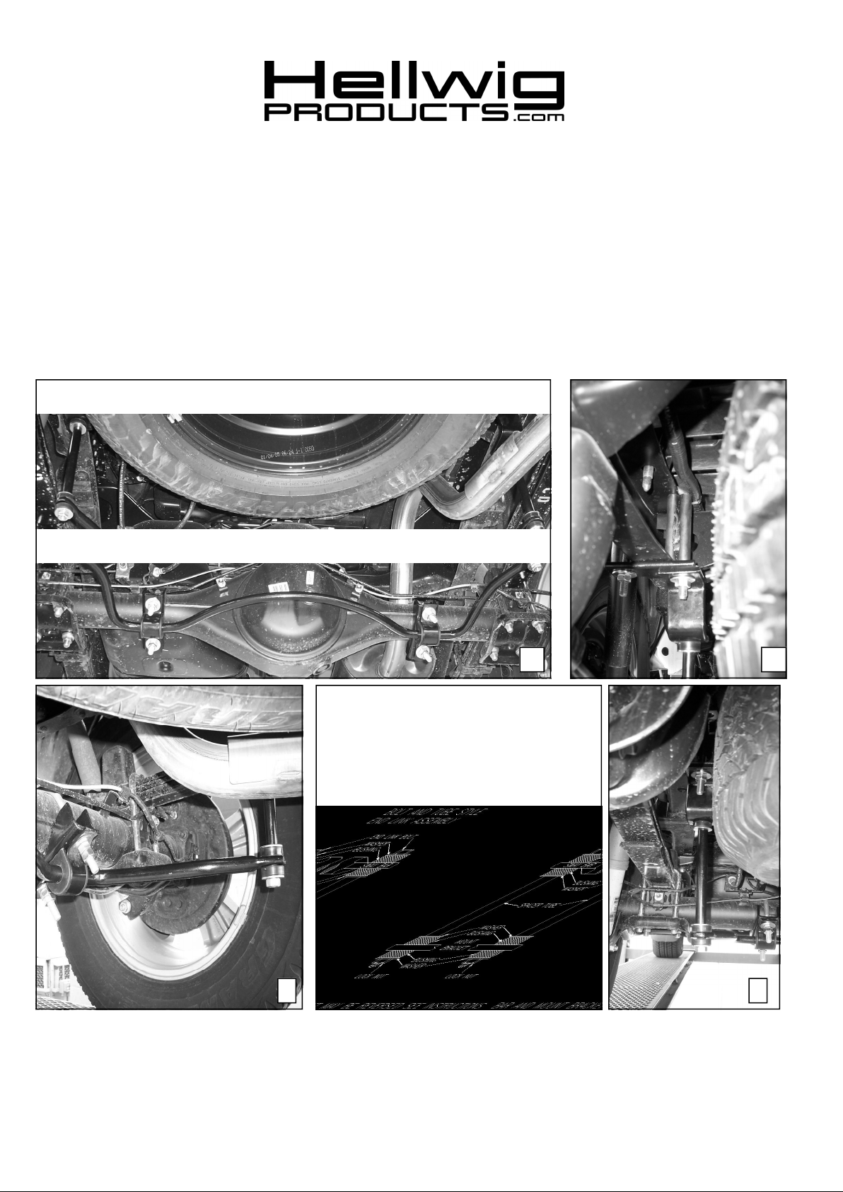
1
3 4
7670 ( R-7671 ) 04/05/05
2

559-734-7451 800-367-5480 FAX 559-734-7460
TORQUE TABLE
BOLT SIZE: 3/8” = 20-30 ft. lbs. – 7/16” = 35-45 ft. lbs. – ½” = 50-70 ft. lbs. – 9/16” = 70-90 ft. lbs.
SAFETY: BEFORE STARTING YOUR INSTALLATION, BE SURE TO SET PARKINGBRAKE AND
CHOCK THE WHEELS.
NOTE: TO EASE INSTALLATION ANDTO PROPERLY ADJUST BAR, THE WEIGHT OF THEVEHICLE
MUST BE ON THE SUSPENSION, AS IF DRIVING DOWN THE ROAD.
DO NOT RAISE THE VEHICLE BY THE FRAME.
NOTE: THIS UNIT IS DESIGNEDTO MOUNT TO THE BOTTOM OF THE VEHICLES AXLE WITH THE
ARMS OF THE SWAY BARTOWARDS THE REAR OF THE VEHICLE.
NOTE: THIS KIT INCLUDES LOCKNUTS WHICH REQUIRE TIGHTENING WITH AWRENCH AFTER
BEING STARTED BY HAND
1. Take and position the U-bolts on the axle and install the saddle brackets to the U-bolts. Position the
D-bushings on the sway bar in a close a position as in photo one (1). Take care with any electrical
wires or brake lines installed on the axle as not to damage or crimp during tightening. ( The brake
lines can be bent slightly to allow clearance for the U-bolts ).
2. Take and position the square U-bolts over the vehicles frame. Position the u-bolt spacers on the vehicles frame, insert the U-bolts leg thru one of the spacers tubes , the other will be positioned just
inside of the upper and lower legs of the vehicles C-channel frame. Install the crossbars supplied to
the u-bolts and attach the Z-brackets to the inner legs of the square U-bolts using the mounting
hardware provided. SEE PHOTO TWO (2). Leave loose at this time to allow for adjustment
later.
3. Position the U-plates over the D-bushings on the sway bar. Raise the sway bar and attach the ubolts that were installed on the vehicles axle using the mounting hardware provided. The U-bolts on
the axle and the D-bushings on the sway bar can be relocated as needed to allow for the best possible fit. Leave loose at this time to allow for adjustment later.
4. Assemble the end link assemblies as in the diagram. Attach the end links to the Z-brackets on the
vehicles frames. Tighten just slightly until the bushing start to bulge as not to damage the
bushings. Raise the arms of the sway bar to the end links and complete the end link assembly. SEE
PHOTOS THREE (3) AND FOUR (4). Again take care as not to over tighten the end links to cause
any damage.
5. With the sway bar center, the arms level with the ground and the end links straight up and down as
possible torque all the mounting hardware to the specified rates. THE AXLE U-BOLTS CAN BE
ROTATED TO ALLOW FOR THE BEST POSSIBLE FIT.
6. Bounce the vehicle up and down check for clearance for all undercarriage components. Check for
clearance on electrical wires, exhaust, brake and fuel lines etc..
7. Test drive the vehicle recheck your installation re-adjust and re-torque as needed.
8. After one week of driving recheck your installation. Re-adjust and torque as required. Re-check
your installation on a monthly regular basis thereafter.
ATTENTION INSTALLER: BESURE THE CUSTOMER RECEIVES THIS INSTRUCTION SHEET,
ALL IMPORTANT NOTE CARDS, WARNING CARDS, AND THE
WARRANTY FORM.
7670 ( R-7671 ) 04/05/05
 Loading...