

Page 1
559-734-7451 800-367-5480 FAX 559-734-7460
INSTALLATION INSTRUCTIONS
7710 Rear Stabilizer Bar
Thank you for purchasing a quality Hellwig Product.
PLEASE READ THIS INSTRUCTION SHEET COMPLETELY BEFORE STARTING YOUR
INSTALLATION
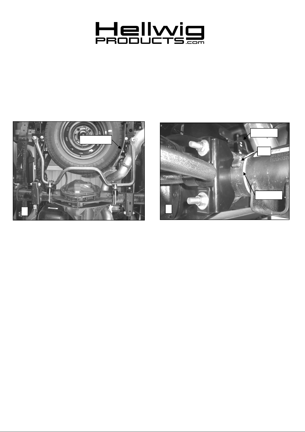
Brake Line
Heat Shield
Clip
Tie Strap
1
SAFETY: BEFORE STARTINGYOUR INSTALLATION,BE SURE TO SET PARKING BRAKE AND CHOCK
TIRES.
NOTE: TO EASE INSTALLATION AND TO PROPERLY ADJUST BAR, THE WEIGHT OF THE VEHICLEMUST
BE ON THE SUSPENSION, AS IF DRIVING DOWN THE ROAD. DO NOT RAISE VEHICLE BY FRAME.
NOTE: THIS UNIT IS DESIGNED TO MOUNT TO THE REAROF THE AXLE TUBES WITH THE ARMSOF THE
BAR TOWARDTHE REAR OF THE VEHICLE. THE HUMP SHOULD TILT SLIGHTLY DOWNWARD.
NOTE: THIS KIT INCLUDES LOCK NUTS WHICH REQUIRE TIGHTENING WITH A WRENCH AFTER BEING
STARTED BYHAND.
1. Remove spare tire from vehicle before beginning installation of sway bar.
2. As shown in photo 1, place D-shaped poly-bushings onto straight areas of the bar on each side of center hump.
After installing D-bushings onto bar, place U-plates on D-bushings. The sway bar will be installed with the hump
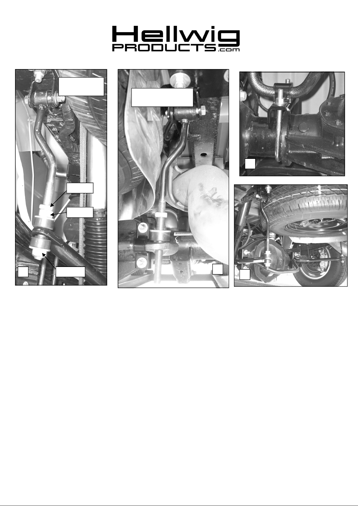
tilted down as shown in photo 7.
3. Place U-bolts on axle tubes next to casting as shown in photos 1, 2, & 6. When installing U-bolts, be sure to put
U-bolts under any brake lines, wires or hoses on the axle to avoid any possible damage.
4. Before installing saddle brackets, remove passenger side brake line from clip and reposition brake line so
that it will clear the saddle bracket as shown in photo 2. Secure brake line with tie strap.
5. Place saddle brackets on axle by inserting legs of U-bolts into the holes in saddle brackets. Saddle brackets must be
installed so that one leg of the saddle bracket is located on the cast center section with the leg just inside the raised
lip on the casting. See photos 1,2,& 6.
6. Raise bar and place D-bushings on saddle brackets by inserting legs of U-bolts through holes in U-plates. Install
flat washers and hex nuts provided on U-bolts. Do not use locknuts provided in kit on axle U-bolts. LEAVE
2
7710(R-7710) 07/09/10
Page 2
559-734-7451 800-367-5480 FAX 559-734-7460
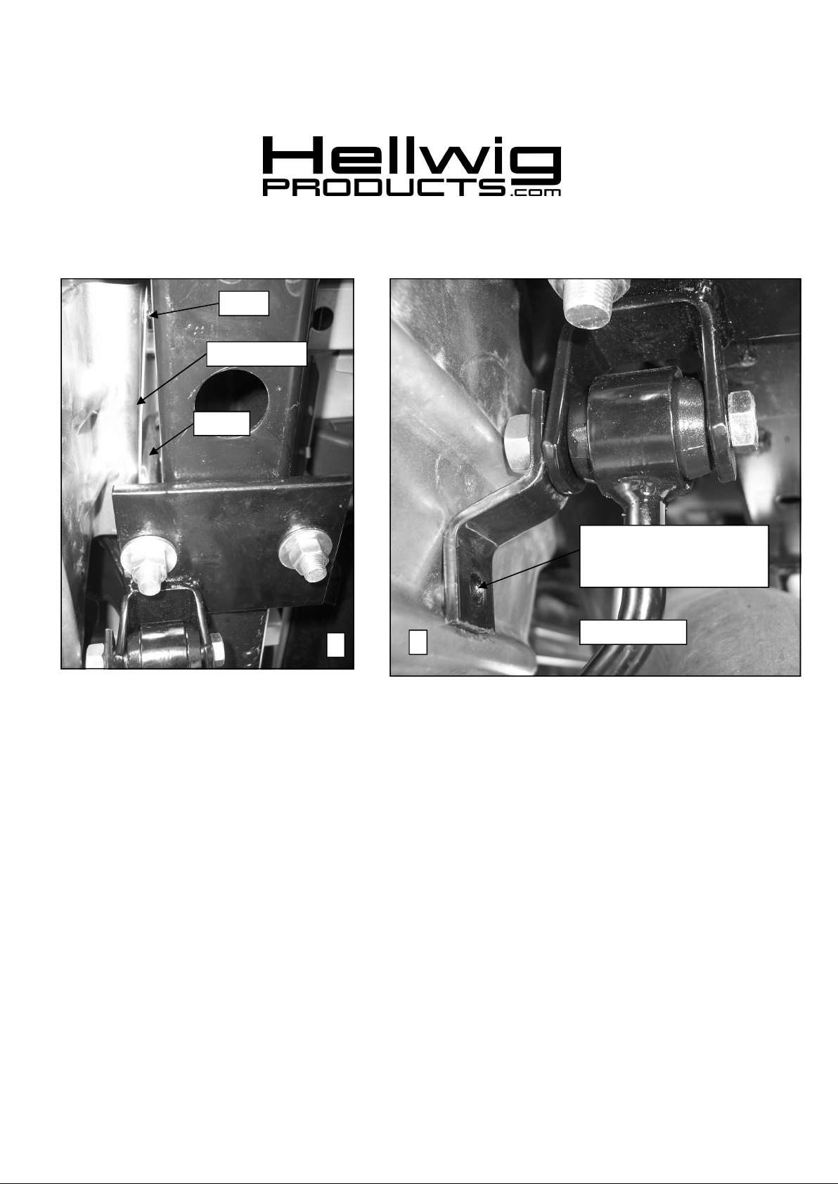
Screw
Heat Shield
U-bolt
Mark heat shield for .281” hole
to attach heat shield to offset
bracket with 1/4” bolt and nut.
3
4
Passenger Side
6. Remove the 2 screws attaching the spare tire heat shield to the passenger side frame rail. Save for use later.
7. Locate existing spare tire crossmember on vehicle frame. Place square U-bolt over frame rail just behind crossmember with
legs of U-bolt pointing downward. On passenger side the inside leg of the U-bolt will fit between the heat shield and the rail
as shown.
8. Insert legs of U-bolt into slotted holes of the hanger brackets. Install hanger brackets with clevis inboard of frame rail and
toward front of vehicle as shown in photo 3. Attach using 1/2” lock nuts. LEAVE LOOSE for adjustment later.
9. Install bushings and spacer tube into the sleeve in end link.
10. Place end link into clevis with offset inboard. Attach end link to clevis with 7/16 X 2 1/4” bolt on driver side. See photo 5a.
On passenger side use the 7/16 x 2-1/2” bolt attach end link and offset bracket to clevis as shown in photo 4 to space the heat
shield away from the end link. LEAVE LOOSE for adjustment later.
11. Install one heat shield screw in hole farthest rearward on frame and tighten until heat shield is flush with the frame rail. Do
not use the other screw.
12. Mark heat shield for hole as shown in photo 4. Drill 9/32 (.281”) hole and attach heat shield to offset bracket with 1/4”
fastener, washers, and lock nut.
7710(R-7710) 07/09/10
Page 3
Driver Side
Jam Nut
Hex Nut
559-734-7451 800-367-5480 FAX 559-734-7460
Passenger Side
6
Lock Nut5a
13. Thread jam nut and hex nut on to threads of end link far enough to mount flat washers and bushings to the end of sway bar as
shown in photo 5a. Attach sway bar to end link using locknuts provided in kit. LEAVE LOOSE AT THIS TIME to allow
for adjustment later.
14. With sway bar loosely mounted, work bar back and forth in D-shaped poly bushings to center bar.
15. Tighten frame bracket U-bolts to 50 ft-lb..
16. Tighten end link clevis bolts to 35 ft-lb.
17. Tighten end link nuts until poly bushings start to bulge slightly. DO NOT OVERTIGHTEN. Tighten jam nut against
upper nut on end link to lock into place.
18. Tighten axle U-bolts to 60 ft-lb. Place second nut on U-bolt and tighten against primary nut to lock in place.
19. Recheck your installation, looking for clearance on any undercarriage components, such as gas lines, exhaust pipes, brake
lines, wiring, differential cover, etc.
20. Drive vehicle for a few miles, then recheck for position and tightness, readjust and retorque as needed. Then recheck
periodically thereafter.
ATTENTION INSTALLER: PLEASE MAKE SURE CUSTOMER RECEIVES THIS INSTRUCTION SHEET,
ALL IMPORTANT NOTE CARDS, WARNING CARDS AND THE WARRANTY
5b
7
7710(R-7710) 07/09/10
 Loading...