

Page 1
559-734-7451 800-367-5480 FAX 559-734-7460
INSTALLATION INSTRUCTIONS
Rear Stabilizer Bar
7821 Ford Lightning 1999-2003
Thank you for purchasing a quality Hellwig Product.
TORQUE TABLE
BOLT SIZE: 3/8” = 20-30 ft. lbs. – 7/16” =35-45 ft. lbs. – ½” = 50-70 ft. lbs. – 9/16” = 70-90ft. lbs.
SAFETY: BEFORE STARTING YOUR INSTALLATION, BE SURE TO SET PARKING BRAKE AND CHOCK TIRES.
NOTE: TO EASE INSTALLATION AND TO PROPERLY ADJUST BAR, THE WEIGHT OF THE VEHICLE MUST BE
ON THE SUSPENSION, AS IF DRIVING DOWN THE ROAD. DO NOT RAISE VEHICLE BY FRAME.
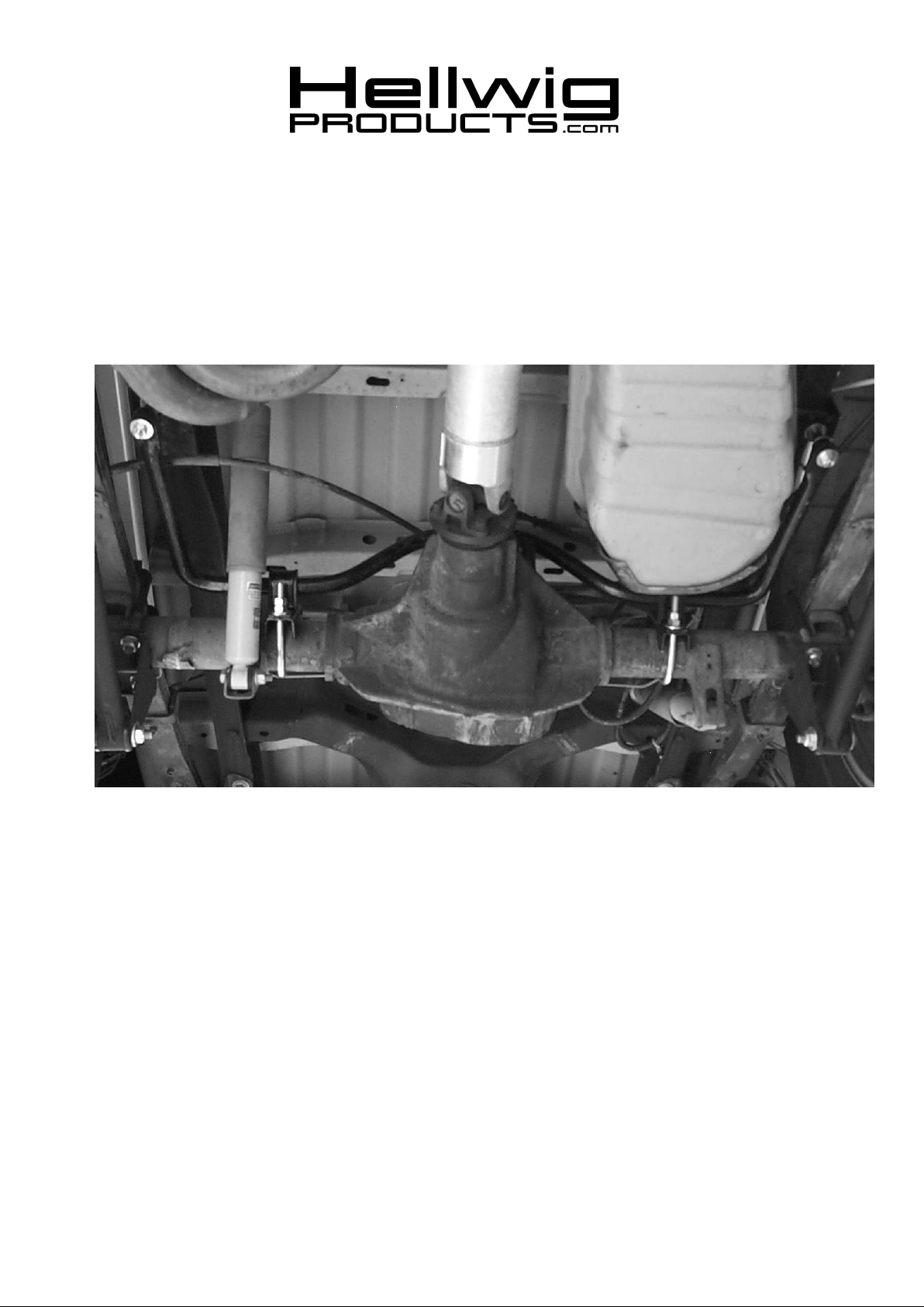
1. Place sway bar over the differential housing as shown in photo 1.
2. Install D-Bushings on the bar in the approximate mounting area.
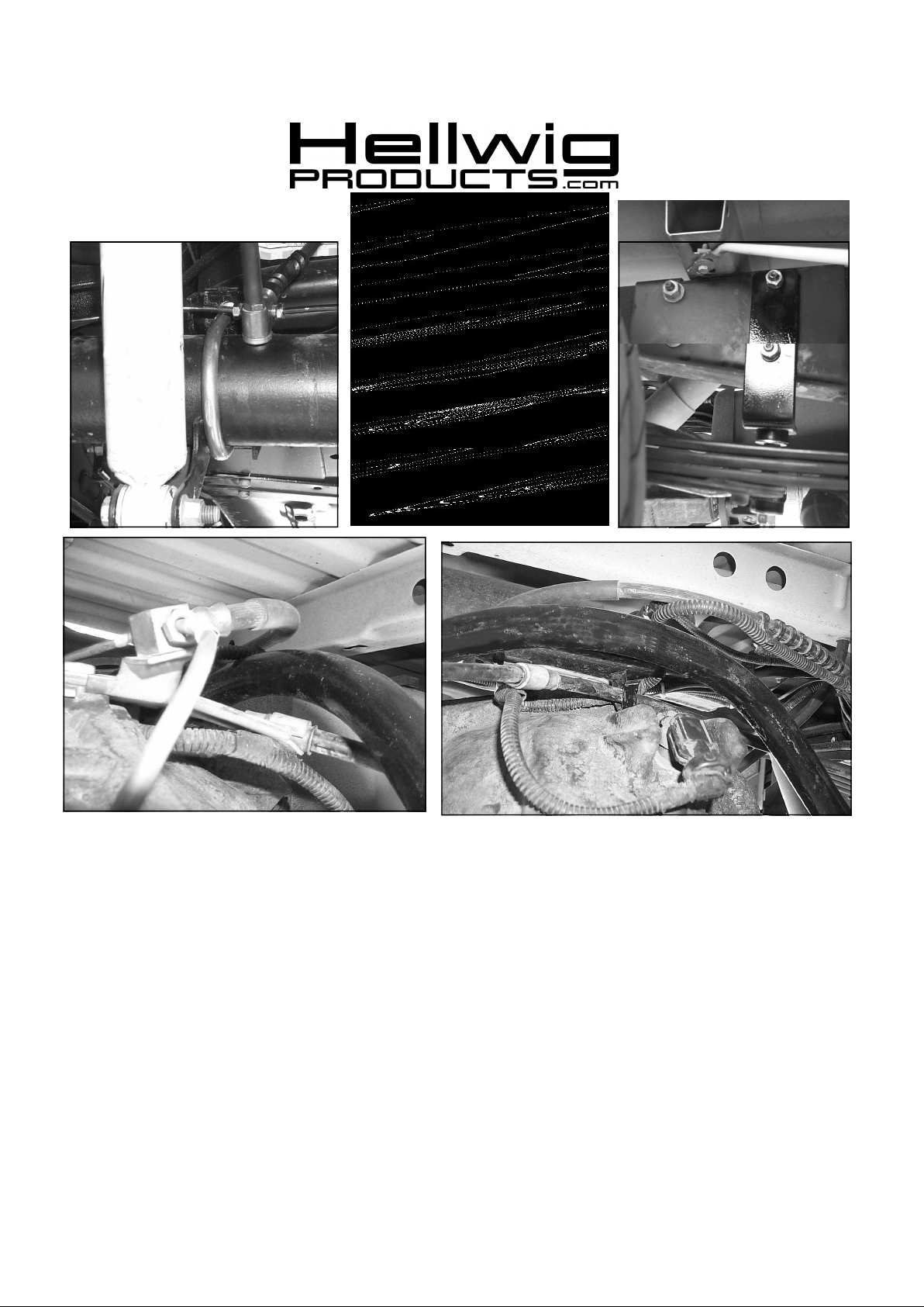
3. If vehicle has brake tee mounted as shown in picture 2 - Disconnect vent tube and remove bolt. Place thick washer under
brake tee as shown in picture 2. Reinstall bolt and connect vent tube.
4. Attach U-bolts, saddle brackets and U-plates as shown in photo 1. Make sure the U-bolts are under the brake lines. DO NOT
TIGHTEN.
5. Attach end links to frame brackets and install 4-hole frame bracket on driver’s side rail using the stud plate and J-bolt in bottom
hole as shown in picture 3. The stud plate installs behind the large slot or hole in the frame rail. The J-bolt hooks over the rail
flange and inserts through the lower hole in the frame bracket. Tighten stud plate to 50 ft-lb. Tighten J-bolt to 30 ft-lb.
7821 ( R-7821) 01/19/04
Page 2
559-734-7451 800-367-5480 FAX 559-734-7460
6. Locate passenger side shock bracket. Remove the factory nuts from the forward shock bracket studs and place the frame
bracket on the studs as shown in picture 4. Fasten bracket to frame using supplied lock washers and M10-1.5 nuts.
Tighten to 30 ft-lb.
7. Attach sway bar to end links. Move sway bar side to side in brackets to center bar in vehicle. Then tighten nuts on end
links until bushings bulge slightly.
8. Adjust sway bar on axle so that there is at least 3/4” clearance between the bar and the axle. Ensure adequate clearance
between the sway bar and all shock absorbers, brake lines, hoses, cables and electrical connections. When all clearances
are confirmed, tighten U-bolts to 60 ft-lb. Double nut and tighten.
9. If vehicle has brake tee mounted on top of axle (pictures 5&6) - Unplug speed sensor and unclip harness from brake tee
bracket and hose. Adjust brake tee and emergency brake brackets so that brake hose and emergency brake cable clear the
sway bar and are oriented as shown in pictures 5&6. Re-route speed sensor harness as shown in picture 6 and reconnect
plug to speed sensor.
10. Bounce vehicle and check for clearance on all undercarriage components. Recheck installation, look for clearance on gas
lines, exhaust pipes, brake lines, wiring, etc. After one week of driving check your installation and every thirty (30) days
7821 ( R-7821) 01/19/04
Page 3

PARTS LIST
KIT # 7821
“99-03” F150 LIGHTING
PART # QTY DESCRIPTION
20217607 1 SWAY BAR 1-1/8” O. D.
111000546 2 (1 1/8”) I.D.
118000156 2 (1/2” X 3-5/8” X 6-1/2’) ROUND U-BOLT
20800871 2 SADDLE BRACKET
20800648 2 U-PLATE
20800555 1 ANGLE BRACKET
20800627 1 J-BOLT
20800790 1 FLAT PLATE WITH WELDED BOLT
101500010 2 (7/16” X 4-1/2”) CAP SCREW
101500779 2 (7/16” X 5”) END LINK
20800012 1 ANGLE BRACKET
111000389 8 END LINK BUSHING
107521044 1 (1/2") LOCK NUT
107401042 3 (7/16") LOCK NUT
107700080 2 (7/16") LOCK NUT
102520043 5 (1/2”) FLAT WASHER
105521044 8 (1/2") HEX NUT
102420041 9 (7/16”) FLAT WASHER
20800723 2 (1/2” X 1-1/4”) END LINK SPACER
20800778 2 (1/2” X 1-3/4”) END LINK SPACER
103420717 2 (7/16") LOCK WASHER
105901015 2 (M10-1.50) METRIC HEX NUT
102400021 1 (1” X 1/4”) THICK FLAT WASHER
135007821 1 INSTRUCTION SHEET R-7821
7821 ( R-7821) 01/19/04
 Loading...