

Hellwig 7669 User Manual
559-734-7451 800-367-5480 FAX 559-734-7460
INSTALLATION INSTRUCTIONS
Rear S tabilizer Bar
NISSAN TITAN
Thank you for purchasing a quality Hellwig Product.
2
1
3 4 5
7669 ( R-7669 ) 05/06/05

PLEASE MAKE SURE CUSTOMER RECEIVES THIS INSTRUCTION SHEET,
559-734-7451 800-367-5480 FAX 559-734-7460
TORQUE TABLE
BOLT SIZE: 3/8” = 20-30 ft. lbs. – 7/16” = 35-45 ft. lbs. – ½” = 50-70 ft. lbs. – 9/16” = 70-90 ft. lbs.
SAFETY: BEFORE STARTING YOUR INSTALLATION, BE SURE TO SET PARKING BRAKE AND CHOCK THE
WHEELS.
NOTE: TO EASE INSTALLATION AND TO PROPERLY ADJUST BAR, THE WEIGHT OF THE VEHICLE MUST
BE ON THE SUSPENSION, AS IF DRIVING DOWN THE ROAD. DO NOT RAISE THE VEHICLE BY
THE FRAME.
NOTE: THIS UNIT IS DESIGNED TO MOUNT TO THE BOTTOM OF THE AXLE WITH THE ARMS OF THE
SWAY BAR POINTING TOWARDS THE REAR OF THE VEHICLE.
NOTE: THIS KIT INCLUDES LOCKNUTS WHICH REQUIRE TIGHTENING WITH A WRENCH AFTER BEING
STARTED BY HAND.
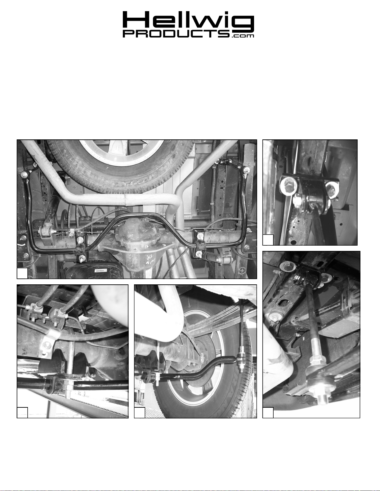
1. Install the U-bolts over the axle with the legs towards the ground as in photo three ( 3 ). Insert the saddle
brackets through the legs of the U-bolts. Install a hex nuts to temporarily support the saddle brackets to the
axle. They will be removed later. Taking care as not to damage the brake or fuel lines mounted on the axle.
2. Locate and insert the D-shaped poly bushings in as close a location that the bushings will contact the U-bolts
and saddle brackets installed on the rear axle. Position the U-plate brackets over the bushings. Remove the
hex nuts supporting the saddle brackets, insert the legs of the U-bolts thru the holes of the U-plate brackets
over the bushings. Tighten the 1/2” hex nuts on the U-bolts just enough to support the sway bar to the axle.
Leave loose at this time to allow for adjustment later. SEE PHOTO ONE (1).
3. Locate the threaded frame brackets on top of the frame rail as shown in photo tow ( 2 ). Attach the frame
brackets with the welded clevis using the 7/16” x 5-1/2” cap screws. Take care as not to damage any electrical wires, brake or fuel lines that run along the vehicles frame. Note that the cap screws will be pointing towards the vehicles body ( up ). Leave loose to allow for adjustment later.
4. Locate the end links and assemble with the poly bushings as in photos ( 4 and 5 ). Insert the hour glass poly
bushings through the welded ends of the end links. Insert the steel sleeves through the hour glass poly bushings. ( To ease installation lightly grease the steel sleeve and the hour glass bushing before assembling ).
5. Insert the end links into the clevis of the frame brackets and attach using the 7/16” x 2-1/4” cap screw and
locknut. Leave loose to allow for adjustment later.
6. Raise the arms of the sway bar and install the end link bushings on the arms of the sway bar as shown in the
photos with the locknut on the bottom of the end link. Tighten the nuts until the poly bushings start to
bulge. Do not over tighten or damage can occur to the poly bushings.
7. With the sway bar centered and the end links straight up and down as possible, torque all mounting components to the specified rates. Note that the bend on the sway bar arms will be towards the top of the vehicle as
in photo ( 4 ).
8. Bounce the vehicle and check for clearance on under carriage components, shocks, exhaust, electrical wires,
brake and fuel lines.
9. Test drive your vehicle recheck your installation readjust and tighten as needed. After one week of driving re
check your installation re-torque as needed. Recheck your installation on a monthly regular basis thereafter.
ATTENTION INSTALLER:
ALL IMPORTANT NOTE CARDS, WARNING CARDS AND THE WARRANTY
FORM
7669 ( R-7669 ) 05/06/05
 Loading...