

559-734-7451 800-367-5480 FAX 559-734-7460
INSTALLATION INSTRUCTIONS
REAR STABILIZER BAR
03-04 DODGE CARAVAN
Thank you for purchasing aquality Hellwig Product.
PLEASE READ THIS INSTRUCTION SHEET COMPLETELY BEFORE STARTING YOUR INSTALLATION
1 2
3
7665 ( R-7665 ) 09/24/04

559-734-7451 800-367-5480 FAX 559-734-7460
TORQUE TABLE
BOLT SIZE:3/8” = 20-30 ft. lbs. – 7/16” = 35-45 ft. lbs. – ½” = 50-70 ft. lbs. – 9/16” = 70-90 ft. lbs
SAFETY: BEFORE STARTING YOUR INSTALLATION, BE SURE TO SET PARKINGBRAKE AND CHOCK TIRES.
NOTE: TO EASE INSTALLATION ANDTO PROPERLY ADJUST THE BAR, THE WEIGHTOF THE VEHICLE MUSTBE
ON THE SUSPENSION, AS IF DRIVING DOWN THE ROAD. DO NOT RAISE VEHICLE BY FRAME.
NOTE: THIS KIT INCLUDES LOCK NUTS WHICHREQUIRE TIGHTENING WITH A WRENCH AFTERBEING STARTED
BY HAND.
NOTE: THIS ANTI-SWAY BARMOUNTS ON THE REAR OF THE AXLE WITH THE ARMS POINTING TOWARDS THE
REAR OF THE VEHICLE.
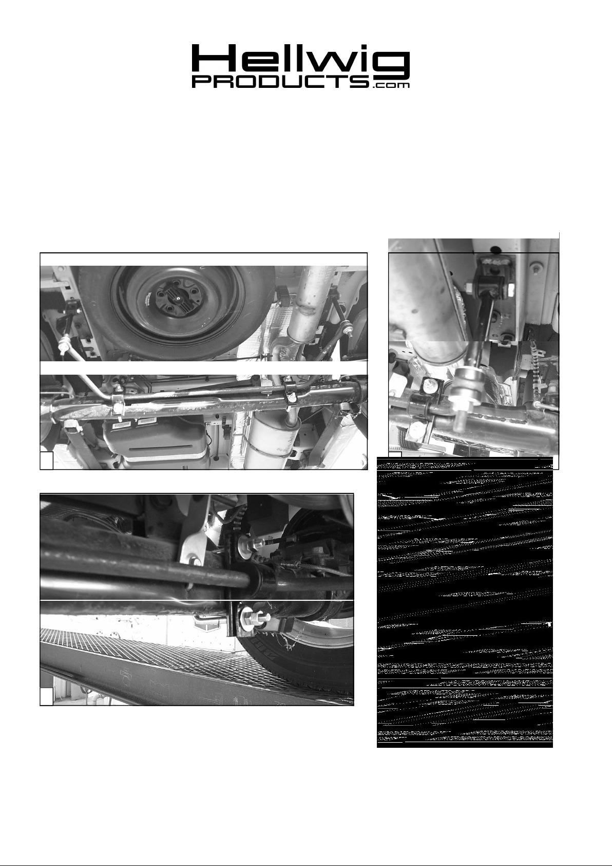
1. Locate the predrilled mounting on the frame rails. Just behind the rear axle assembly. Install the
frame brackets using the that are provided in this kit. Leave loose at this time to allow for adjust-
ment later. SEE PHOTO TWO (2).
2. Install the U-bolts on the rear axle with the legs towards the rear of the vehicle. Be sure that the
brake lines are outside of the U-bolt legs and will not be damaged when tightening the U-bolts.
3. Install the D-shaped poly bushings on the sway bar as close as possible to match the U-bolts that
are mounted on the axle. SEE PHOTOS ONE (1) AND THREE (3).
4. Raise the sway bar up to the axle. Position the U-plates over the D-bushings. Using the mounting
hardware provided tighten enough to support the sway bar on the axle. Leave loose at this time to
allow for adjustment later.
5. Assemble the end link assemblies. SEE DIAGRAM. Install the tube ends of the end links to the
frame brackets that were installed in STEP ONE (1). Note it may be necessary to lightly grease the
poly bushings and steel sleeves to ease installation.
6. Raise the sway bar arms up to the end link assemblies. Finish the installation of the sway bar arms
to the end links. SEE DIAGRAM. Tighten until the bushings start to bulge slightly. Over tight-
ening will cause damage to the bushings.
7. With the sway bar centered on the axle and the end links are straight up and down as possible
torque all the mounting hardware to their specified rate. ( The sway bar can be rotated on the axle
and the end links adjusted by the frame hardware ).
8. Check your installation check for clearance on undercarriage components; wires, exhaust, brake
and fuel lines.
9. After one week of driving recheck your installation readjust if necessary. Recheck your installation
on a monthly regular basis thereafter.
ATTENTION INSTALLER: BE SURE THAT THE CUSTOMER RECEIVES THIS INSTRUCTION SHEET,
ALL IMORTANT NOTE CARDSAND THEWARRANTY FORM
7665 ( R-7665 ) 09/24/04

559-734-7451 800-367-5480 FAX 559-734-7460
PARTS LIST
RSB # 7665
03-04 CARAVAN
PART # QTY DESCRIPTION
20217629 1 3/4” SWAY BAR
20800430 2 U-PLATE
20800023 2 WELDED FRAME BRACKET
20800350 2 PLATE BRACKET
20800796 2 7/6” X 8” WELDED END LINK
118000512 2 7/16” X 3-1/4 X 4-5/8 SQUARE U-BOLT
20800227 2 5/8” X 4-1/4” END LINK SPACER
111000496 2 3/4” D-SHAPED POLY BUSHING
125020005 1 SMALL PARTS BAG # BG-5
101500185 2 7/16” X 2-1/4” CAP SCREW
107401042 4 7/16" LOCK NUT
102420041 8 7/16” FLAT WASHER
105421042 8 7/16" HEX NUT
101500046 4 M10 X 30 METRIC CAP SCREW
111000853 4 5/8” POLY BUSHING
20800722 2 STEEL SLEEVE
111000389 4 END LINK BUSHING
135007665 1 INSTRUCTION SHEET R-7665
7665 ( R-7665 ) 09/24/04
 Loading...