

Hellwig 7663 User Manual
559-734-7451 800-367-5480 FAX 559-734-7460
INSTALLA TION INSTRUCTIONS
7663 REAR STABILIZER BAR
Thank you for purchasing a quality Hellwig Product.
PLEASE READ THIS INSTRUCTION SHEET COMPLETELY BEFORE STARTING YOUR INSTALLATION
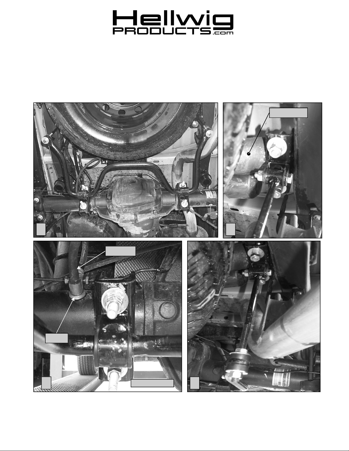
Crossmember
1
Washer
2
Vent Tube
DRIVERS SIDE
3
4
7663 ( R-7663 ) 02/19/04

559-734-7451 800-367-5480 FAX 559-734-7460
SAFETY: BEFORE STARTING YOUR INSTALLATION, BE SURE TO SET PARKING BRAKE AND CHOCK TIRES.
NOTE: TO EASE INSTALLATION AND TO PROPERLY ADJUST THE BAR, THE WEIGHT OF THE VEHICLE MUST BE
ON THE SUSPENSION, AS IF DRIVING DOWN THE ROAD. DO NOT RAISE VEHICLE BY THE FRAME.
NOTE: THIS SWAY BAR IS DESIGNED TO MOUNT ON THE REAR OF THE DIFFERENTIAL WITH THE ARMS TO
WARDS THE REAR OF THE VEHICLE.
NOTE: THIS KIT INCLUDES LOCK NUTS WHICH REQUIRES TIGHTENING WITH A WRENCH AFTER BEING
STARTED BY HAND.
TORQUE TABLE
BOLT SIZE: 3/8” = 20-30 ft. lbs. – 7/16” = 35-45 ft. lbs. – ½” = 50-70 ft. lbs. – 9/16” = 70-90 ft. lbs.-5/8”=120 ft. lbs.
1. Install the D-shaped poly bushings on the flat areas of the sway bar. Between the hump and the arms of the sway bar. When the
sway bar is mounted the hump should tilt slightly downward.
2. Disconnect vent tube and remove bolt. Place thick washer under brake tee as shown in picture 2. Reinstall bolt and connect vent
tube.
3. Position the U-bolts on the axle tubes just inside of the shock mounts. The threads should be pointing downward. Make sure that
the U-bolts are under any brake lines, wires or hoses on the axle to avoid pinching or crushing when the U-bolts are tightened.
4. Install the U-plates over the D-bushings on the sway bar. Install the saddle brackets on the U-bolts that are on axle tubes. Attach
the U-plates to the U-bolts using the 1/2” hex nuts and the flat washers that are provided. Leave loose at this time to allow for
adjustment.
5. Rotate the sway bar on the axle tubes and adjust side to side so that the sway bar is as centered as possible. Check and make sure
the sway bar has enough clearance around the differential housing.
6. Assemble the pivot bushings and sleeves into the ends of the end links.
7. Locate the tubular crossmember above the spare tire just inside the frame rails. See picture three (3). Position the shorter set of Ubolts on the crossmember with the legs pointing down. Install the saddle brackets with the welded U-shaped clevis on the crossmember using 1/2” locknuts and flatwashers. Make sure the U-bolts are under any lines or wires to avoid pinching or crush-
ing when tightened. Leave loose at this time to allow for adjustment later.
8. Attach the end link assemblies to the upper clevis brackets using 7/16 X 2 1/4” bolt. Leave loose at this time to allow for adjust-
ment later.
9. Thread locknuts on to the threads of the end links far enough to mount flat washers and bushings to the end of sway bar as shown
in photo four (4). Attach sway bar to end link using locknuts provided in kit. LEAVE LOOSE AT THIS TIME to allow for
adjustment later..
10. Rotate the U-bolts on the axle and the tubular crossmember to align the sway bar to be as level with the frame and that the end
links are straight up and down as possible. Recheck the axle and crossmember U-bolts make sure that there are no wires,
hoses or brake lines underneath to avoid pinching or crushing when tightened.
11. With the sway bar properly aligned, ensure that all the vehicle components have the proper clearance, and no wires or hoses will
be crushed or pinched when tightened.
12. Tighten frame crossmember U-bolts to 50 ft-lb.
13. Tighten end link nuts until poly bushings start to bulge slightly. DO NOT OVERTIGHTEN
14. Torque all other mounting hardware to the specified rates. Double nut the axle U-bolts and tighten to lock nuts in place.
15. Bounce the vehicle, check for clearance on all undercarriage components; exhaust, wires, shocks, brake and fuel lines. Test drive
the vehicle and recheck for clearance and installation alignment.
16. After one week of driving recheck your installation recheck on a monthly regular basis thereafter.
ATTENTION INSTALLER: BE SURE THAT THE CUSTOMER RECEIVES THIS INSTRUCTION SHEET,
ALL IMORTANT NOTE CARDS AND THE WARRANTY FORM
7663 ( R-7663 ) 02/19/04
 Loading...