

559-734-7451 800-367-5480 FAX 559-734-7460
INSTALLATION INSTRUCTIONS
FRONT STABILIZER BAR
(00-04) 6.1 & 8.1 SUBRUBAN, AVALANCHE
(2500-3500) 2 & 4 WHL DR
Thank you for purchasing a quality Hellwig Product.
PLEASE READ THIS INSTRUCTIONSHEET COMPLETELYBEFORESTARTING YOUR INSTALLATION
2
1
TORQUE TABLE
BOLT SIZE: 3/8” = 20-30 ft. lbs. – 7/16” = 35-45 ft. lbs. – ½” = 50-70 ft. lbs. – 9/16” = 70-90 ft. lbs.
SAFETY: BEFORESTARTINGYOUR INSTALLATION,BE SURE TO SET PARKINGBRAKE AND CHOCKTIRES.
NOTE: TO EASEINSTALLATIONAND TO PROPERLYADJUSTBAR, THE WEIGHT OF THE VEHICLEMUSTBE ON THE
SUSPENSION, AS IF DRIVING DOWN THE ROAD. DO NOT RAISE VEHICLE BY FRAME.
NOTE: THIS UNIT IS DESIGNED TO REPLACE THEFACTORYINSALLEDFRONT SWAY BAR USINGTHEFACTORY U-PLATE
MOUNTING BOLTS.
1. Remove the factory installed front skid plate. ( Remember this procedure,you will have to reinstall the front skid plate later).
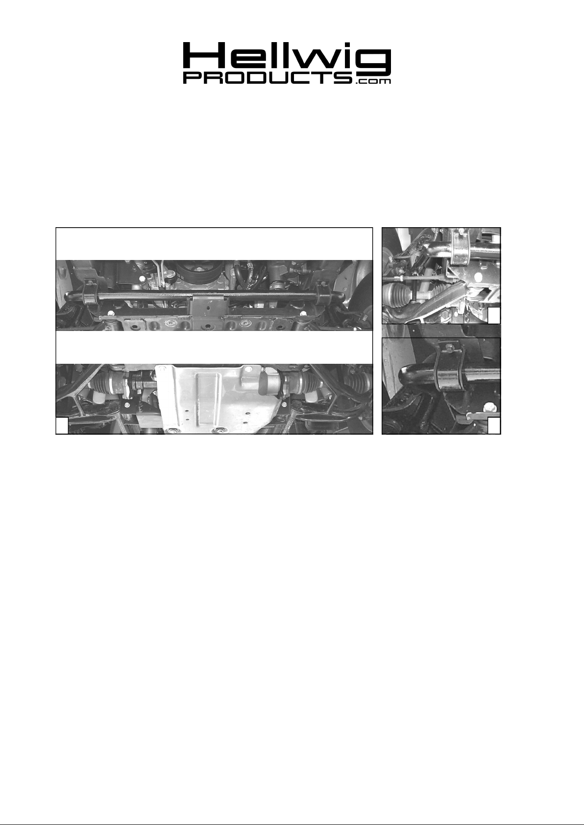
2. Install the U-plates to the factory sway bar frame mounts that are welded to the frame. Start the self tapping bolts closest to the bumper first. Leave
loose at this time. These U-plates will have to be rotated out of the way to allow for clearance when installing the sway bar. See photos one (1)
and two (2).
3. Install the end links on the lower control arms. TIGHTEN SLIGHTLY JUST UNTIL BUSHING START TO BULGE. See photothree (3) and the
line drawing. DO NOT OVER TIGHTEN.
4. Install the D-shaped poly bushings on the swaybar in approximately the same location so that the bushings line up with the U-plateson the frame.
SEE PHOTOONE (1).
5. Raise the sway bar up into position onto the end links and rotate the U-plates around the D-shaped poly bushings so the U-plates are supporting the
sway bar.
6. Start the remaining self tapping bolts on the other end of the U-plates. Leave loose at this time to allow for adjustment. See photo one (1).
7. By moving the sway bar to the right or to the left. The end links can be aligned in as near up and down as possible.
8. Tighten all the self tapping bolts on the U-plates to the factory specifications.
9. Reinstall the factory installed front skid plate that you removed in step one (1). Torque to factory specifications.
3
10. Bounce the vehicle and check for clearance on all the undercarriage components. Turn the front wheels full lock left and then to the right making
sure that you have a minimum of ( 1 inch) of clearance is maintained between the tie rod and the swat bar. Be sure that all nuts and bolts securely
tightened. Check and see that all wires, fuel and brake lines etc. are all clear of this installation and cannot be damaged. Recheck your installation
after one (1) week of driving and every thirty days thereafter.
ATTENTION INSTALLER: BE SURE THAT THE CUSTOMER RECEIVES THIS INSTRUCTION SHEET, ALL IMORTANT NOTE
CARDSAND THEWARRANTY FORM
7654 ( R-7654 ) 07/08/04

559-734-7451 800-367-5480 FAX 559-734-7460
PARTS LIST
FSB KIT # 7654
“00-04” 6.1 & 8.1 SUBURBAN 2 & 4 WHL DR
PART # QTY DESCRIPTION
20217654 1 ( 1-1/2” ) SWAY BAR
20800870 2 U-PLATE
111000869 2 ( 1-1/2” ) POLY BUSHING
20800225 2 ( 1/2” X 5” ) END LINK SPACER
101500751 2 ( 7/16” X 9” ) END LINK
125030336 1 END LINK BUSHING BAG # BG-336
111000389 8 END LINK BUSHING
125000077 1 SMALL PARTS BAG # BG-77
107700080 2 ( 7/16" ) LOCK NUT
102400023 8 ( 7/16” ) FLAT WASHER
135007654 1 INSTRUCTION SHEET R-7654 (R 281)
7654 ( R-7654 ) 07/08/04
 Loading...