

Hellwig 7650 User Manual
559-734-7451 800-367-5480 FAX 559-734-7460
INSTALLA TION INSTRUCTIONS
Rear Stabilizer Bar
1500 SUBURBAN,XL1500,TAHOE,YUKON DENALI,ESCALADE &
AVALANCHE (NEW BODY STYLE W/REAR COIL SPRINGS)
Thank you for purchasing a quality Hellwig Product.
PLEASE READ THIS INSTRUCTION SHEET COMPLETELY BEFORE STARTING YOUR INSTALLATION
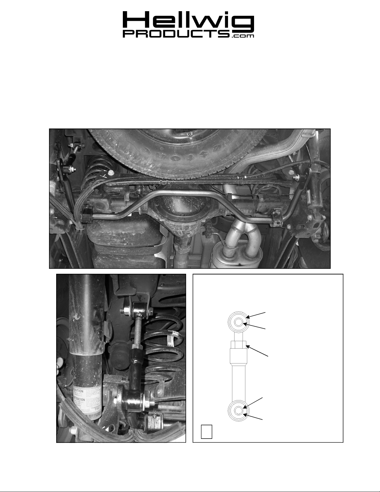
End Link Assembly
Bushing
Sleeve
9/16-18 Nut
Sleeve
Bushing
3
7650 (R-7650) 07/12/2006

559-734-7451 800-367-5480 FAX 559-734-7460
INSTALLA TION INSTRUCTIONS
Rear Stabilizer Bar
00-03 1500 SUBURBAN,XL1500,TAHOE,YUKON DENALI,ESCALADE &
AVALANCHE (NEW BODY STYLE W/REAR COIL SPRINGS)
Thank you for purchasing a quality Hellwig Product.
PLEASE READ THIS INSTRUCTION SHEET COMPLETELY BEFORE STARTING YOUR INSTALLATION
TORQUE TABLE
SAFETY: BEFORE STARTING YOUR INSTALLATION, BE SURE TO SET PARKING BRAKE AND CHOCK TIRES.
NOTE: TO EASE INSTALLATION AND TO PROPERLY ADJUST BAR, THE WEIGHT OF THE VEHICLE MUST BE ON THE SUS-
PENSION, AS IF DRIVING DOWN THE ROAD. DO NOT RAISE VEHICLE BY FRAME.
NOTE: THIS UNIT IS DESIGNED TO REPLACE THE FACTORY INSTALLED REAR ANTI-SWAY BAR. THE HARDWARE CON-
NECTING THE BAR TO THE AXLE AND THE END LINKS TO THE FRAME WILL HAVE TO BE REUSED.
NOTE: THIS KIT INCLUDES LOCK NUTS WHICH REQUIRE TIGHTENING WITH A WRENCH AFTER BEING STARTED BY HAND.
BOLT SIZE: 3/8” = 20-30 ft. lbs. – 7/16” = 35-45 ft. lbs. – ½” = 50-70 ft. lbs. – 9/16” = 70-90 ft. lbs.
1. Remove the factory installed rear anti-sway bar and all the mounting hardware. Keep the hardware connect-
ing the sway bar to the axle and the end links to the frame. THEY WILL HAVE TO BE REUSED.
2. As per the photos, lubricate and install the D-shaped poly bushings onto the bar in the same location as the
factory installed bushings on the sway bar. Place the U-plates over the D-bushings and attach the bar to the
axle using the mounting hardware removed in step number one (1), Leave loose at this time to allow for
adjustment later. Use supplied grease to lubricate D -bushings.
3. As per the diagrams, assemble the adjustable pivot end links and attach together. Use supplied grease to
lubricate the hourglass bushings and sleeves before assembly. The 3/4” diameter sleeve is used at the top of
the end links to attach to the frame bracket and hardware.
4. Attach the end links using the thick washers, bushing and lock nut as shown in photos. Leave loose at this
time to allow for adjustment later.
5. Center the sway bar under the vehicle by moving the bar side to side. Adjust the end links so that the sway
bar is as level with the frame as possible. Tighten all mounting hardware to the specified rates.
6. Bounce the vehicle checking for clearance on all undercarriage components. Readjust the bar as needed and
check on periodically on a regular basis thereafter.
ATTENTION INSTALLER: BE SURE THAT THE CUSTOMER RECEIVES THIS INSTRUCTION SHEET,
ALL IMORTANT NOTE CARDS AND THE WARRANTY FORM
7650 (R-7650) 07/12/2006
 Loading...