

Hellwig 7649 User Manual
559-734-7451 800-367-5480 FAX 559-734-7460
INSTALLATION INSTRUCTIONS
Rear Stabilizer Bar
00-04 2500 SUBURBAN & AVALANCHE
8.1 2&4 WHL
Thank you for purchasing a quality Hellwig Product.
PLEASE READ THIS INSTRUCTION SHEET COMPLETELY BEFORE STARTINGYOUR INSTALLATION
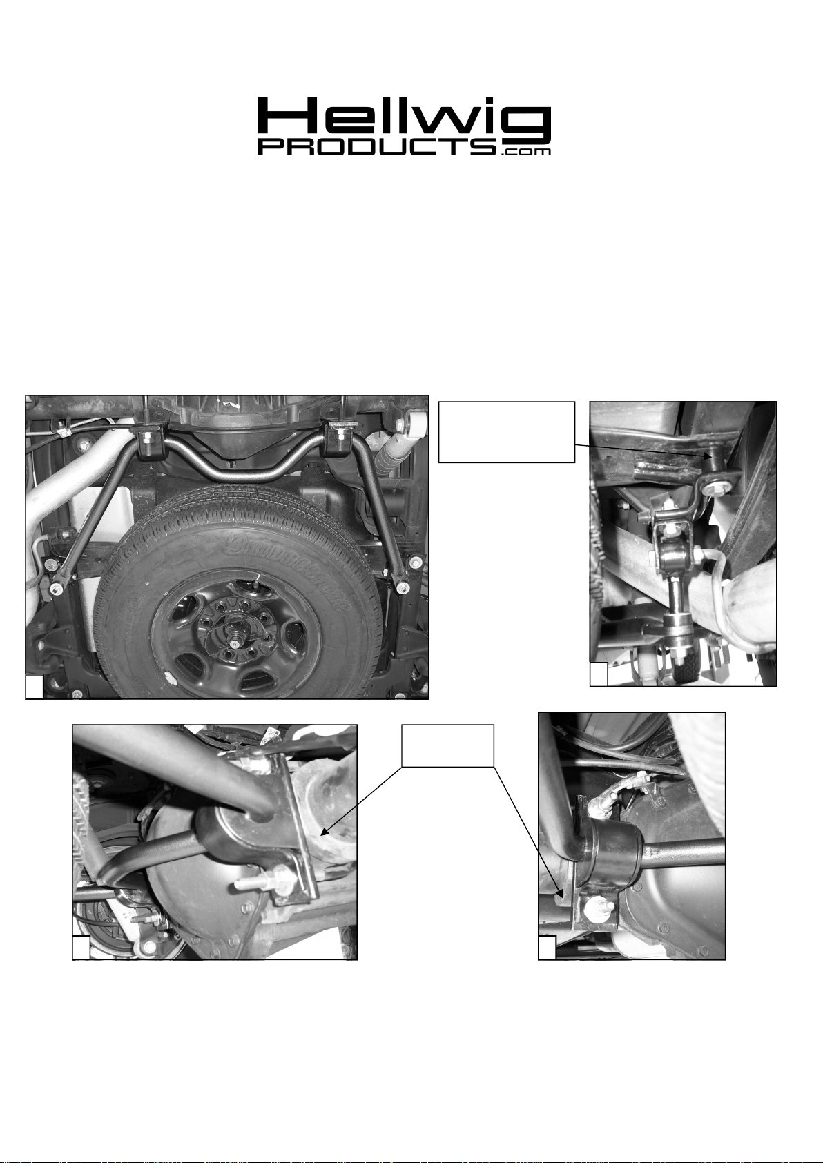
SPACER PLATE &
50MM X 1.5 X M12
CAPSCREW
1
REAR AXLE
CASTING
2
7649 (R-382 ) 12/09/04
4
3

559-734-7451 800-367-5480 FAX 559-734-7460
TORQUE TABLE
BOLT SIZE: 3/8” = 20-30 ft. lbs. – 7/16” = 35-45 ft. lbs. – ½” = 50-70 ft. lbs. – 9/16” =70-90 ft. lbs.— 12mm = 45-55 ft.lbs
SAFETY: BEFORE STARTING YOUR INSTALLATION,BE SURE TO SETPARKINGBRAKE ANDCHOCK TIRES.
NOTE: TO EASE INSTALLATION AND TOPROPERLY ADJUSTBAR, THEWEIGHT OF THE VEHICLE MUSTBEONTHE
SUSPENSIONAS IF DRIVINGDOWN THE ROAD.DONOT RAISE VEHICLE BY FRAME.
NOTE: THIS KIT IS DESIGNED TOFIT THE8.1 LITER3/4 TON SUBURBANAND AVALANCHE WITH AHEAVY DUTY REARAXLE
ONLY.
NOTE: THIS KIT INCLUDES LOCK NUTSWHICH REQUIRE TIGHTENING WITHAWRENCH AFTERBEING STARTED BY HAND.
1. This sway bar is NOT symmetrical and is designed to install with the wide angled arm to the passenger side. The arms
of the sway bar will point towards the rear of the vehicle. See photo one ( 1).
2. Locate the large round cast lugs on the rear of the differential housing at each side near the axle tubes. The flat plates
and sway bar mounting hardware will be located over these lugs. See photos two ( 2 ) & three ( 4 ) .
3. Install the D-shaped polyurethane bushings between the center hump and the arms of the sway bar. Install the U-plates
over the D-bushings on the sway bar. (To avoid any possible bushing noise, you can apply a thin layer of automotive
grease on the inside of the D-bushings).
4. Install the large flat 3-hole plates on the rear of the differential lugs so that the offset in the plates center hole is upward
thus placing the U-plates low on the differential.
5. Install the U-bolts over the axle tubes in line with the flat 3-hole plates, so the threads are through the flat plates. Be
sure to place the U-bolts under any brake lines, hoses or wires on the differential to avoid crushing when the Ubolts are tightened later.
6. Install the sway bar with the bushings and U-plates on the backside of the differential housing. Adjust the bushing and
U-plates so they align with the U-bolts that are installed on the axle tubes. Install the U-plates onto the U-bolts and
tighten with the flat washers and double nuts that are provided. Leave loose at this time to allow for adjustment later.
7. Locate the single bolt on each side of the spare tire cross member/carrier rearward of the axle assy. Remove bolts ( one
side at a time). Use a C-clamp to hold the cross member/carrier or block up the spare tire so it cannot drop down.
Spare tire can be removed to ease installation.
8. Install the Z-bracket to the frame pointing inward the Z-bracket can be rotated as needed to allow for adjustment. Leave
loose at this time to allow for adjustment later. Install the clevis brackets to the Z-brackets, on the passenger side the
spacer plate and the 50mm x 1.5 x 12mm cap screw will be used to mount the Z-bracket to the vehicles frame. See
photo three ( 3 ).
9. Assemble the end links by installing the hour shaped poly bushing through the sleeved end of the end link. Insert the
steel sleeve through the poly bushing. It may be necessary to slightly grease the steel sleeve and the poly bushing to
ease installation ( taking care as not to damaged the poly bushings ). Install the assembled end link on the mounted Zbrackets. Leave loose at this time to allow for adjustment later. ( See photo three (3).
10. Raise the sway bar arms up to the installed end links. Using the remaining ( 4 ) round poly bushing install the sway bar
arms to the end links. Tighten just slightly that the poly bushings start to bulge. Do not over tighten or damage can
occur to the poly bushings.
11. Rotate the U-bolts on the axle so that the sway bar is as level to the frame, and the end links are straight up and down as
possible. Be sure the axle u-bolts are under any brake lines, wires or hoses to avoid any possible damage. With the
bar properly aligned and you have enough clearance on the differential and nothing will be crushed or pinched during
tightening. Torque all mounting hardware to the specified rates and double nut the axle U-bolts.
12. Bounce the vehicle check for clearance on all undercarriage components; exhaust, shocks, brake and fuel lines. Test
drive the vehicle and recheck your installation readjust if needed. Recheck your installation on a monthly regular basis
thereafter.
ATTENTION INSTALLER: BE SURE THATTHE CUSTOMERRECEIVESTHIS INSTRUCTIONSHEET, ALL
IMORTANT NOTE CARDSAND THE WARRANTY FORM
7649 (R-382 ) 12/09/04
 Loading...