

Hellwig 7623 User Manual
559-734-7451 800-367-5480 FAX 559-734-7460
INSTALLATION INSTRUCTIONS
REAR STABILIZER BAR
97-07 G1500, SAVANA, EXPRESS VAN
Thank you for purchasing a quality Hellwig Product.
PLEASE READ THISINSTRUCTION SHEETCOMPLETELY BEFORE STARTINGYOUR INSTALLATION
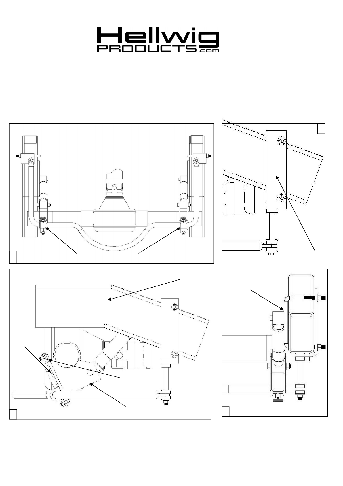
Swaybar mounting under vehicles axle
2
1
U-plates
3
D-bushing location on swaybar
Bent plate
Lower axle shock mount brackets
Frame bracket
Vehicles frame
Square U-bolts
4
7623 ( R-7623 ) 05/05/07

559-734-7451 800-367-5480 FAX 559-734-7460
TORQUETABLE
BOLT SIZE: 3/8” = 20-30 ft. lbs. – 7/16” = 35-45 ft. lbs. – ½” = 50-70 ft. lbs. – 9/16” = 70-90 ft. lbs.-5/8”=120 ft. lbs.
SAFETY: BEFORE STARTING YOUR INSTALLATION,BE SURE TO SET PARKINGBRAKE AND CHOCK
TIRES.
IMPORTANT: WHEN JACKING UP THE VEHICLE BE SURE THE VEHICLE IS SUPPORTEDWITH JACK
STANDSAND CANNOT FALL.
NOTE: THIS KIT INCLUDES LOCK NUTS WHICH REQUIRE TIGHTENINGWITH A WRENCH AFTER
BEING STARTEDBY HAND.
NOTE: THIS SWAY BAR IS DESIGNED TO MOUNT TO THE REAR AXLE SHOCKMOUNTBRACKETS
WITH THE SWAYBAR ARMSPOINTINGTOWARDSTHE FRONT OF THE VEHICLE.
1. Place the D-shaped poly bushings on the flat areas of the sway bar on each side of the center
hump. Align the D-bushings on the sway bar with the lower shock mount brackets that area
welded to the rear axle assembly. SEE PHOTO ( 1 ).
2. Place the U-plates over the D-bushings on the sway bar. Position the U-plates that the long
ends of the U-plates point upwards. Insert the bent plates between the axle and the shock
mount brackets. Attach the U-plates to the bent plates with hardware provided. The threads
of the attaching bolts should be towards the rear of the vehicle. LEAVE LOOSE AT THIS
TIME TO ALLOW FOR ADJUSTMENT LATER. SEE PHOTO ( 3 ).
3. Assemble the end links assemblies and attach to the swaybar. As shown in photo ( 2 ).
Tighten the lock nuts on the end links just slightly until the bushings start to bulge. Do not
over tighten or damage to the bushings can occur. Attach the frame brackets to the end
links assemblies. NOTE: there is a left and a right frame bracket.
4. Position the square U-bolts on the vehicles frame from the inside out. Be careful as not to
damage or pinch any wires, brake or fuel lines on the vehicles frame. SEE PHOTO ( 4 ).
5. Raise and rotate the sway bar up to the vehicles frame. Insert the square U-bolts through the
holes on the frame brackets and attach with hardware provided. Tighten enough to support
the swaybar, leave loose at this time to allow for adjustment later. Again check that there
are no electrical wires, brake or fuel lines that will pinched or damages when tightening the
mounting hardware to the U-bolts. The excess threads on the square U-bolts can be trimmed
to avoid contact with the vehicles leaf spring assembly.
6. Center the swaybar on the axle, with the arms level with the ground and with the end links
straight up and down as possible. Torque all mounting hardware to specified rates. .
7. Bounce the vehicle, check for clearance on all undercarriage components, exhaust, shocks,
electrical wires, brake and fuel lines. Test drive the vehicle recheck your installation readjust as needed. Drive the vehicle for a week recheck installation readjust if needed. Check
your installation on a monthly basis thereafter.
ATTENTION INSTALLER: BE SURE THAT THE CUSTOMERRECEIVESTHIS INSTRUCTIONSHEET,
ALL IMORTANT NOTE CARDS AND THE WARRANTYFORM
7623 ( R-7623 ) 05/05/07
 Loading...