

Page 1

User’s Manual
MANUALplus
4110
NC Software
526 488-xx
English (en)
9/2007
Page 2

MANUALplus 4110, Software and Functions
This manual describes functions that are available in
MANUALplus 4110 controls with NC software numbers
507 807-xx and 526 488-xx.
The machine manufacturer adapts the features offered by the control
to the capabilities of the specific machine tool by setting machine
parameters. Therefore, some of the functions described in this manual
may not be among the features provided by the MANUALplus on your
machine tool.
Some of the MANUALplus functions which are not available on every
machine are:
Positioning of spindle (M19) and driven tool
Machining with the C Axis
Please contact your machine manufacturer for detailed information on
the features that are supported by your machine tool.
Many machine manufacturers and HEIDENHAIN offer programming
courses for the MANUALplus controls. We recommend these courses
as an effective way of improving your programming skills and sharing
information and ideas with other MANUALplus users.
HEIDENHAIN also offers the PC software DataPilot 4110 which is
designed to simulate the functions of the MANUALplus 4110 control.
The DataPilot is suitable for both shop-floor programming as well as
off-location program creation and testing. It is also ideal for training
purposes. The DataPilot can be run on WINDOWS operating systems.
Intended place of operation
The MANUALplus 4110 complies with EN 55022, Class A, and is
intended primarily for operation in industrially zoned areas.
Page 3

Contents
Introduction and Fundamentals
1
Basics of Operation
Machine Mode of Operation
Cycle Programming
ICP Programming
DIN Programming
Tool Management Mode
Organization Mode of Operation
Examples
Tables and Overviews
2
3
4
5
6
7
8
9
10
HEIDENHAIN MANUALplus 4110 3
Page 4

Page 5

1 Introduction and Fundamentals 19
1.1 The MANUALplus ..... 20
The C axis ..... 20
1.2 Features ..... 21
1.3 MANUALplus Design ..... 22
Lathe design ..... 22
Machine operating panel ..... 24
1.4 Axis Designations and Coordinate System ..... 25
Axis designations ..... 25
Coordinate system ..... 25
Absolute coordinates ..... 26
Incremental coordinates ..... 26
Polar coordinates ..... 26
1.5 Machine Reference Points ..... 27
Machine zero point ..... 27
Workpiece zero point ..... 27
Reference points ..... 27
1.6 Tool Dimensions ..... 28
Tool length ..... 28
Tool compensation ..... 28
Tool-tip radius compensation (TRC) ..... 28
Milling cutter radius compensation (MCRC) ..... 29
HEIDENHAIN MANUALplus 4110 5
Page 6

2 Basics of Operation 31
2.1 The MANUALplus Screen ..... 32
2.2 Operation and Data Input ..... 33
Modes of operation ..... 33
Menu selection ..... 33
Soft keys ..... 33
Data input ..... 34
List operations ..... 34
Alphanumeric keyboard ..... 35
2.3 Error Messages ..... 36
Direct error messages ..... 36
Error display ..... 36
Clearing an error message ..... 37
System error, internal error ..... 37
PLC error, PLC status display ..... 37
Warnings during simulation ..... 38
2.4 Explanation of Terms ..... 39
6
Page 7

3 Machine Mode of Operation 41
3.1 Machine Mode of Operation ..... 42
3.2 Switch-On / Switch-Off ..... 43
Switch-on ..... 43
Traversing the reference marks ..... 43
Monitoring EnDat encoders ..... 44
Switch-off ..... 45
3.3 Machine Data ..... 46
Input and display of machine data ..... 46
Tool call ..... 47
Tools in different quadrants ..... 48
Feed rate ..... 48
Spindle ..... 49
3.4 Machine Setup ..... 50
Defining the workpiece zero point ..... 50
Setting the protection zone ..... 51
Defining the tool change position ..... 52
Setting C-axis values ..... 53
3.5 Setting up Tools ..... 54
Tool compensation ..... 58
Tool life monitoring ..... 59
3.6 Manual Mode ..... 60
Tool change ..... 60
Spindle ..... 60
Handwheel operation ..... 60
Jog operation (joystick) ..... 60
Cycles in Manual mode ..... 61
3.7 Teach-In Mode ..... 62
3.8 Program Run Mode ..... 63
Faulty programs ..... 63
Before executing a program ..... 63
Start block search and program execution ..... 64
Entering compensation values during program execution ..... 65
Setting compensation values with the handwheel ..... 66
Program execution in “dry run” mode ..... 67
HEIDENHAIN MANUALplus 4110 7
Page 8

3.9 Graphic Simulation ..... 68
Views ..... 70
Graphic elements ..... 71
Warnings ..... 72
Magnify / Reduce ..... 73
3.10 Time Calculation ..... 74
3.11 Program Management ..... 75
Program information ..... 75
Functions for program management ..... 76
3.12 Conversion into DIN Format ..... 77
3.13 Inch Mode ..... 78
4 Cycle Programming 79
4.1 Working with Cycles ..... 80
Starting point of cycles ..... 80
Cycle transitions ..... 80
DIN macros ..... 81
Graphical test run (simulation) ..... 81
Cycle keys ..... 81
Switching functions (M functions) ..... 82
Comments ..... 82
Cycle menu ..... 83
Soft keys in cycle programming ..... 84
4.2 Workpiece Blank Cycles ..... 85
Blank—bar/tube ..... 86
ICP workpc. blank contour ..... 87
4.3 Single Cut Cycles ..... 88
Rapid traverse positioning ..... 89
Approach the tool change position ..... 90
Linear machining, longitudinal ..... 91
Linear machining, transverse ..... 92
Linear machining at angle ..... 93
Circular machining ..... 94
Chamfer ..... 95
Rounding ..... 96
M functions ..... 97
8
Page 9

4.4 Roughing Cycles ..... 98
Roughing, longitudinal/transverse ..... 101
Roughing, longitudinal/transverse—Expanded ..... 103
Finishing cut, longitudinal/transverse ..... 105
Finishing cut, longitudinal/transverse—Expanded ..... 107
Plunge longitudinal/transverse ..... 109
Plunge, longitudinal/transverse—Expanded ..... 111
Finishing plunge, longitudinal/transverse ..... 113
Finishing plunge, longitudinal/transverse—Expanded ..... 115
ICP contour-parallel, longitudinal/transverse ..... 117
ICP contour-parallel finishing, longitudinal/transverse ..... 119
ICP roughing, longitudinal/transverse ..... 121
ICP finishing, longitudinal or transverse ..... 123
Examples of roughing cycles ..... 125
4.5 Recessing cycles ..... 129
Recessing, radial/axial ..... 131
Recessing, radial/axial—Expanded ..... 133
Recessing radial/axial, finishing ..... 135
Recessing radial/axial, finishing—Expanded ..... 137
ICP recessing cycles ..... 139
ICP recessing radial/axial, finishing ..... 141
Recess turning ..... 143
Recess turning, radial/axial ..... 144
Recess turning, radial/axial—Expanded ..... 146
Recess turning radial/axial, finishing ..... 148
Recess turning radial/axial, finishing—Expanded ..... 150
ICP recess turning, radial/axial ..... 152
ICP recess turning radial/axial, finishing ..... 154
Undercut type H ..... 156
Undercut type K ..... 157
Undercut type U ..... 158
Parting ..... 159
Examples of recessing cycles ..... 160
HEIDENHAIN MANUALplus 4110 9
Page 10

4.6 Thread and Undercut Cycles ..... 162
Thread cycle (longitudinal) ..... 165
Thread cycle (longitudinal)—Expanded ..... 166
Tapered thread ..... 168
API thread ..... 170
Recut (longitudinal) thread ..... 172
Recut (longitudinal) thread—Expanded ..... 174
Recut tapered thread ..... 176
Recut API thread ..... 178
Undercut DIN 76 ..... 180
Undercut DIN 509 E ..... 182
Undercut DIN 509 F ..... 184
Examples of thread and undercut cycles ..... 186
4.7 Drilling Cycles ..... 190
Drilling, axial/radial ..... 191
Deep-hole drilling, axial/radial ..... 193
Tapping, axial/radial ..... 195
Thread milling, axial ..... 197
Examples of drilling cycles ..... 199
4.8 Milling Cycles ..... 201
Rapid traverse positioning ..... 202
Slot, axial ..... 203
Figure, axial ..... 204
ICP contour, axial ..... 208
Face milling ..... 211
Slot, radial ..... 215
Figure, radial ..... 216
ICP contour, radial ..... 220
Helical-slot milling, radial ..... 223
Cutting direction for contour milling and pocket milling ..... 224
Examples of milling cycles ..... 226
4.9 Drilling/Milling Patterns ..... 227
Drilling/milling pattern linear, axial ..... 228
Drilling/milling pattern circular, axial ..... 230
Drilling/milling pattern linear, radial ..... 232
Drilling/milling pattern circular, radial ..... 234
Examples of pattern machining ..... 236
4.10 DIN Cycles ..... 239
10
Page 11

5 ICP Programming 241
5.1 ICP Contours ..... 242
5.2 Editing ICP Contours ..... 243
Programming and adding to ICP contours ..... 244
Absolute or incremental dimensions ..... 244
Transitions between contour elements ..... 245
Contour graphics ..... 246
Changing the ICP contour graphics ..... 247
Selection of solutions ..... 248
Contour direction ..... 249
5.3 Importing of DXF Contours ..... 250
Fundamentals ..... 250
DXF import ..... 251
Configuring the DXF import ..... 252
5.4 Programming Changes to ICP Contours ..... 254
Editing a contour element ..... 254
Adding a contour element ..... 257
Deleting a contour element ..... 257
"Splitting" a contour ..... 258
Superimposing form elements ..... 259
5.5 ICP Contour Elements, Turning Contour ..... 260
Entering lines, turning contour ..... 260
Entering circular arcs, turning contour ..... 262
Entering form elements ..... 263
Chamfer/rounding, turning contour ..... 264
Undercuts, turning contour ..... 265
5.6 ICP Contour Elements on the Face ..... 268
Entering lines on the face ..... 269
Entering circular arcs on the face ..... 270
Entering chamfers/roundings on the face ..... 271
5.7 ICP Contour Elements on the Lateral Surface ..... 272
Entering lines on the lateral surface ..... 273
Entering circular arcs on the lateral surface ..... 274
Entering chamfers/roundings on the lateral surface ..... 275
HEIDENHAIN MANUALplus 4110 11
Page 12

6 DIN Programming 277
6.1 DIN Programming ..... 278
Program and block structure ..... 279
6.2 Editing DIN Programs ..... 281
Block functions ..... 281
Word functions ..... 283
Address parameters ..... 283
Comments ..... 284
Block functions ..... 285
Menu structure ..... 286
Programming G functions ..... 287
6.3 Definition of Workpiece Blank ..... 288
Chuck part, cylinder/tube G20 ..... 288
Workpiece blank contour G21 ..... 289
6.4 Tool Positioning without Machining ..... 290
Rapid traverse G0 ..... 290
Tool change point G14 ..... 291
6.5 Simple Linear and Circular Movements ..... 292
Linear path G1 ..... 292
Circular path G2, G3—incremental center coordinates ..... 293
Circular path G12, G13—absolute center coordinates ..... 295
6.6 Feed Rate and Spindle Speed ..... 297
Speed limitation G26/G126 ..... 297
Interrupted feed G64 ..... 297
Feed per tooth G193 ..... 298
Constant feed G94 (feed per minute) ..... 298
Feed per revolution G95/G195 ..... 298
Constant cutting speed G96/G196 ..... 299
Spindle speed G97/G197 ..... 299
6.7 Tool-Tip / Milling-Cutter Radius Compensation ..... 300
Fundamentals ..... 300
G40: Switch off TRC/MCRC ..... 301
G41/G42: Switch on TRC/MCRC ..... 301
6.8 Compensation Values ..... 302
(Changing the) cutter compensation G148 ..... 302
Additive compensation G149 ..... 303
Compensation of right-hand tool nose G150
Compensation of left-hand tool nose G151 ..... 304
6.9 Zero Point Shifts ..... 305
Zero point shift G51 ..... 305
Additive zero point shift G56 ..... 306
Absolute zero point shift G59 ..... 307
12
Page 13

6.10 Oversizes ..... 308
Axis-parallel oversize G57 ..... 308
Contour-parallel oversize (equidistant) G58 ..... 309
6.11 Contour-Based Turning Cycles ..... 310
Contour definition ..... 310
End of cycle G80 ..... 310
Longitudinal contour roughing G817/G818 ..... 311
Longitudinal contour roughing with recessing G819 ..... 313
Transverse contour roughing G827/G828 ..... 314
Transverse contour roughing with recessing G829 ..... 316
Contour-parallel roughing G836 ..... 317
Contour finishing G89 ..... 318
6.12 Simple Turning Cycles ..... 319
Roughing longitudinal G81 ..... 319
Roughing transverse G82 ..... 320
Simple contour repeat cycle G83 ..... 321
Line with radius G87 ..... 322
Line with chamfer G88 ..... 323
6.13 Recessing Cycles ..... 324
Contour recessing axial G861 / radial G862 ..... 324
Contour recessing cycle, finishing, axial G863 / radial G864 ..... 326
Simple recessing cycle, axial G865 / radial G866 ..... 328
Recessing finishing, axial G867 / radial G868 ..... 329
Simple recessing cycle G86 ..... 330
6.14 Recess-Turning Cycles ..... 331
Function of recess turning cycles ..... 331
Simple recess-turning cycle, longitudinal G811 / transverse G821 ..... 332
Recess-turning cycle, longitudinal G815 / transverse G825 ..... 333
6.15 Thread Cycles ..... 335
Universal thread cycle G31 ..... 335
Single thread G32 ..... 337
Thread single path G33 ..... 338
Metric ISO thread G35 ..... 339
Simple longitudinal single-start thread G350 ..... 340
Extended longitudinal multi-start thread G351 ..... 341
Tapered API thread G352 ..... 342
Tapered thread G353 ..... 343
HEIDENHAIN MANUALplus 4110 13
Page 14

6.16 Undercut Cycles ..... 344
Undercut contour G25 ..... 344
Undercut cycle G85 ..... 345
Undercut according to DIN 509 E with cylinder machining G851 ..... 347
Undercut according to DIN 509 F with cylinder machining G852 ..... 348
Undercut according to DIN 76 with cylinder machining G853 ..... 349
Undercut type U G856 ..... 350
Undercut type H G857 ..... 351
Undercut type K G858 ..... 352
6.17 Parting Cycle ..... 353
Parting cycle G859 ..... 353
6.18 Drilling Cycles ..... 354
Drilling cycle G71 ..... 354
Deep-hole drilling cycle G74 ..... 355
Tapping G36 ..... 357
Thread milling, axial G799 ..... 358
6.19 C-Axis Commands ..... 359
Zero point shift, C axis G152 ..... 359
Standardize C axis G153 ..... 359
6.20 Face Machining ..... 360
Starting point of contour / rapid traverse G100 ..... 360
Linear segment, face G101 ..... 361
Circular arc, face G102/G103 ..... 362
Linear slot, face G791 ..... 363
Contour and figure milling cycle, face G793 ..... 364
Area milling, face G797 ..... 366
Figure definition: Full circle, face G304 ..... 368
Figure definition: Rectangle, face G305 ..... 369
Figure definition: Eccentric polygon, face G307 ..... 370
6.21 Lateral Surface Machining ..... 371
Reference diameter G120 ..... 371
Starting point of contour / rapid traverse G110 ..... 372
Linear segment, lateral surface G111 ..... 373
Circular arc, lateral surface G112/G113 ..... 374
Linear slot, lateral surface G792 ..... 376
Contour and figure milling cycle, lateral surface G794 ..... 377
Helical-slot milling G798 ..... 379
Figure definition: Full circle, lateral surface G314 ..... 380
Figure definition: Rectangle, lateral surface G315 ..... 381
Figure definition: Eccentric polygon, lateral surface G317 ..... 382
14
Page 15

6.22 Pattern Machining ..... 383
Linear pattern, face G743 ..... 383
Circular pattern, face G745 ..... 385
Linear pattern, lateral surface G744 ..... 387
Circular pattern, lateral surface G746 ..... 389
6.23 Other G Functions ..... 391
Period of dwell G4 ..... 391
Precision stop G9 ..... 391
Deactivate protection zone G60 ..... 391
Wait for moment G204 ..... 391
6.24 Set T, S, F ..... 392
Tool number, spindle speed /cutting speed and feed rate ..... 392
6.25 Data Input and Data Output ..... 393
INPUT ..... 393
WINDOW ..... 394
PRINT ..... 395
6.26 Programming Variables ..... 396
Fundamentals ..... 396
# variables ..... 397
V variables ..... 399
6.27 Program Branches, Program Repeats ..... 401
IF (...) (conditional program branch) ..... 401
WHILE (program repeat) ..... 402
6.28 Variables as Address Parameters ..... 403
6.29 Subprograms ..... 406
6.30 M Functions ..... 408
HEIDENHAIN MANUALplus 4110 15
Page 16

7 Tool Management Mode 411
7.1 Tool Management Mode of Operation ..... 412
Tool types ..... 412
Tool life management ..... 413
7.2 Tool Organization ..... 414
7.3 Tool Texts ..... 416
7.4 Tool Data ..... 418
Tool orientation ..... 418
Reference point ..... 418
Editing tool data ..... 418
Lathe tools ..... 419
Recessing and recess-turning tools ..... 421
Thread-cutting tools ..... 422
Drilling tools ..... 423
Tapping tools ..... 424
Milling tools ..... 425
7.5 Tool Data—Supplementary Parameters ..... 426
Driven tool ..... 426
Direction of rotation ..... 426
Cutting data ..... 426
Tool life management ..... 427
16
Page 17

8 Organization Mode of Operation 429
8.1 Organization Mode of Operation ..... 430
8.2 Parameters ..... 431
Current parameters ..... 432
Configuration parameters ..... 435
8.3 Transfer ..... 441
Data backup ..... 441
Data exchange with DataPilot 4110 ..... 441
Printer ..... 441
Interfaces ..... 442
Basics of data transfer ..... 442
Configuring for data transfer ..... 444
Transferring programs (files) ..... 446
8.4 Service and Diagnosis ..... 453
Access authorization ..... 453
System service ..... 455
Diagnosis ..... 455
9 Examples 457
9.1 Working with MANUALplus ..... 458
Setting up the machine ..... 459
Selecting a cycle program ..... 460
Creating a cycle program ..... 461
9.2 ICP Example "Threaded Stud" ..... 470
9.3 ICP Example "Matrix" ..... 483
9.4 ICP Example "Recessing Cycle" ..... 495
9.5 ICP Example "Milling Cycle" ..... 507
9.6 DIN Programming Example "Threaded Stud" ..... 516
9.7 DIN Programming Example "Milling Cycle" ..... 519
10 Tables and Overviews 523
10.1 Thread Pitch ..... 524
10.2 Undercut Parameters ..... 525
DIN 76—undercut parameters ..... 525
DIN 509 E, DIN 509 F—undercut parameters ..... 527
10.3 Technical Information ..... 528
10.4 Peripheral Interface ..... 532
HEIDENHAIN MANUALplus 4110 17
Page 18

Page 19
Introduction and Fundamentals
Page 20
1.1 The MANUALplus
The MANUALplus control combines modern control
and drive technology with the functional features of a
hand-operated machine tool. You can run simple
machining operations, such as turning or facing, on
MANUALplus just like on any conventional lathe. The
axes are moved as usual by handwheel or joystick. For
machining difficult contours, such as tapers, radii,
chamfers, undercuts or threads, MANUALplus offers
fixed cycles. These cycles enable you to work faster
and produce a higher quality than on a conventional
lathe.
In addition, you can teach in a machining sequence
1.1 The MANUALplus
and then have MANUALplus rerun the machining
operation automatically as often as desired. Each
additional part machined saves you time.
MANUALplus offers a wide range of capabilities:
From performing simple lathe jobs through to
complex workpiece contours, including drilling and
milling operations on the face and lateral surface.
MANUALplus lets you choose between manual,
semi-automatic and automatic operation. Regardless
of whether you are machining a single part, producing
a whole batch or repairing a workpiece, MANUALplus
always gives you optimum support.
The C axis
With a C axis you can drill and mill a workpiece on its
front, back and lateral surfaces.
During use of the C axis, one axis interpolates linearly
or circularly with the spindle in the given working
plane, while the third axis interpolates linearly.
MANUALplus supports cycle and DIN programming
with the C axis.
20 1 Introduction and Fundamentals
Page 21

1.2 Features
The functions of the MANUALplus are grouped into operating modes:
Machine mode of operation
This operating mode includes all functions for machine setup,
workpiece machining, and cycle and DIN program definition.
The cycle programming functions are available in both manual
and automatic modes. You can program cycles for roughing,
recessing, thread-cutting and drilling operations.
ICP programming (Interactive Contour Programming) enables
you to describe complex and even incomplete contours. You need
to enter the values for the known elements, MANUALplus then
automatically calculates the transitions, intersections, and any
other missing data. MANUALplus graphically displays the contour
sections entered and calculated. You can usually program a
contour with the dimensions given in the workpiece drawing. ICP
contour descriptions are included in the machining cycles.
The DIN programming feature (NC programming in DIN format
according to DIN 66025 (ISO 6983)) enables you to run highly
complex, technologically sophisticated machining operations.
Apart from pure traversing commands, DIN cycles also provide
functions for roughing, drilling and milling, for programming
schematic contour geometry to calculate missing data, and for
programming variables. You can even write separate DIN
programs or integrate DIN macros in cycles.
Before executing a part program, you can run a graphic
simulation of all machining operations that were programmed
with cycles, cycle programs, or DIN programs.
Tool management mode
MANUALplus stores and manages up to 99 tool definitions.
MANUALplus stores all of the tool data required for calculating
cutting radius compensation, proportioning of cuts, plunging angle,
etc.
1.2 Features
With the tool data, MANUALplus also manages the data for tool life
monitoring as well as the cutting data, feed rate and spindle speed.
Organization mode of operation
The behavior of the MANUALplus system is controlled by
parameters. In the Organization mode, you set the parameters to
adapt the MANUALplus to your situation.
Furthermore, you can exchange and save cycles and DIN programs
with other systems over a serial data line (PC, host computer, etc).
This operating mode also provides diagnostic functions for
commissioning and checking the system.
HEIDENHAIN MANUALplus 4110 21
Page 22

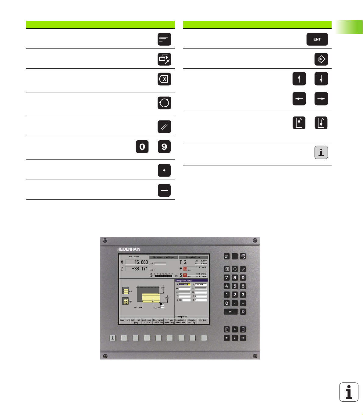
1.3 MANUALplus Design
The dialog between machinist and control takes place via:
Screen
Soft keys
Data input keypad
Machine operating panel
The entered data can be displayed and checked on the screen. With
the function keys directly below the screen, you can select functions,
capture position values, confirm entries, and a lot more.
With the information key (also found beneath the screen), you can
call error and PLC information and activate the PLC diagnostic
function.
The data input keyboard (operating panel) serves for the input of
1.3 MANUALplus Design
machine data, positioning data, etc. The MANUALplus does not need
an alphanumeric keyboard. Tool descriptions, program descriptions or
comments in a DIN program are entered with an on-screen
alphanumeric keyboard.
The machine operating panel contains all necessary controls for
manual operation of the lathe.
The actual control is not accessible to the machinist. You should know,
however, that your MANUALplus has an integrated hard disk on which
all cycle programs, ICP contours and DIN programs that you enter are
stored. This allows you to save a vast number of programs.
For data exchange and data backup, you can use the serial data
interface (RS-232-C) or the Ethernet interface.
Lathe design
MANUALplus is configured by the machine manufacturer as a vertical
boring and turning mill or to machine with tools "in front of" or "behind"
the workpiece—depending on the design of the lathe or the position
of the tool carrier. The menu symbols, the graphic support windows
as well as the graphic representation during ICP and graphic
simulation all reflect the configuration of the lathe.
The representations in this User's Manual assume a lathe with tool
carrier in front of the workpiece.
22 1 Introduction and Fundamentals
Page 23
Data input keypad Symbol
Menu
Call the main menu.
Data input keypad Symbol
ENTER
Confirm the entered value.
Process
Select a new mode of operation.
Backspace
Delete the character to the left of the
cursor.
Switching key
Switch between help graphics for
internal/external machining.
Clear
Delete error messages.
Numbers (0 to 9)
For entering values and selecting soft
keys.
Decimal point
Minus
Enter the algebraic sign.
Store
Conclude data input and transfer values.
Arrow keys
Move the cursor in the indicated
direction by one position (character,
field, line, etc.).
Page up, Page down (PgUp/PgDn)
Show the information of the previous/
next screen page; toggle between two
input windows.
Info
Call the error information or PLC status
display.
1.3 MANUALplus Design
HEIDENHAIN MANUALplus 4110 23
Page 24
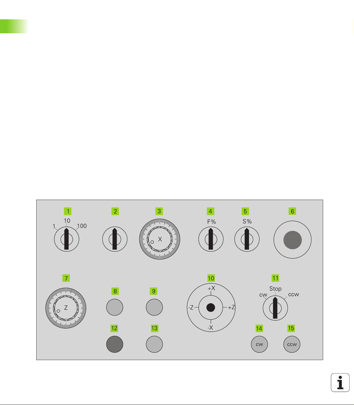
Machine operating panel
The machine operating panel is interfaced to the lathe by the
machine tool builder. The controls on your machine may
deviate slightly from those shown in the illustration. Your
machine documentation provides more detailed information.
Controls and displays
1 Handwheel resolution
Set the handwheel resolution to 1/10 mm, 1/100 mm or 1/
1000 mm per graduation mark—or to other resolutions
defined by the machine tool builder.
2 Handwheel superposition in thread cycles
Set the handwheel to "superposition for thread cycles."
3 X handwheel
Position the cross slide (cross slide axis = X axis).
4 Feed-rate override
1.3 MANUALplus Design
Change the programmed feed rate.
5 Speed override
Change the preset speed.
6 EMERGENCY STOP button
7Z handwheel
Position the saddle (saddle axis = Z axis).
8Tool change
Confirm a tool change.
9 Coolant ON/OFF
Enable/disable coolant supply.
10 Joystick
Move the slide on a linear path at feed rate or rapid
traverse; with a built-in switch for enabling rapid traverse.
11 Spindle switch
Switch spindle to clockwise rotation (cw),
counterclockwise rotation (ccw), or spindle stop (M05).
12 Cycle STOP
Stop traverse and cycle execution (the spindle remains
ON).
13 Cycle START
Start a cycle, cycle program or NC program.
14 Spindle jog cw
Slowly rotate the spindle clockwise (cw).
15 Spindle jog ccw
Slowly rotate the spindle counter-clockwise (ccw).
24 1 Introduction and Fundamentals
Page 25
1.4 Axis Designations and
Coordinate System
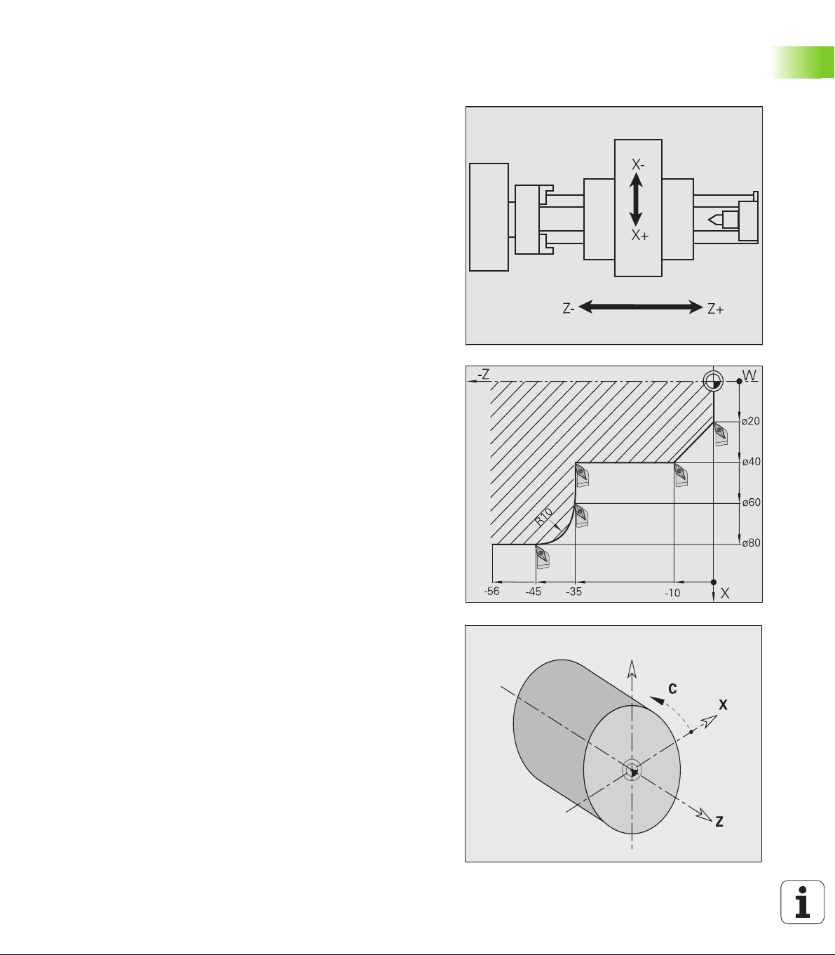
Axis designations
The cross slide is referred to as the X axis and the saddle as the Z axis
(see figure at top right).
All X-axis values that are displayed or entered are regarded as
diameters.
When programming paths of traverse, remember to:
Program a positive value to depart the workpiece.
Program a negative value to approach the workpiece.
Coordinate system
The axis designations X and Z describe positions in a two-dimensional
coordinate system. As you can see from the figure to the center right,
the position of the tool tip is clearly defined by its X and Z coordinates.
MANUALplus can connect points by linear and circular paths of
traverse (interpolations). Workpiece machining is programmed by
entering the coordinates for a succession of points and connecting the
points by linear or circular paths of traverse.
Like the paths of traverse, you can also describe the complete contour
of a workpiece by defining single points through their coordinates and
connecting them by linear or circular paths of traverse.
The coordinates entered for the X axis and Z axis are referenced to
the workpiece zero point.
Angles entered for the C axis are referenced to the zero point of the
C axis (see bottom-right figure).
Positions can be programmed to an accuracy of 1 µm (0.001 mm). This
is also the accuracy with which they are displayed.
1.4 Axis Designations and Coordinate System
HEIDENHAIN MANUALplus 4110 25
Page 26
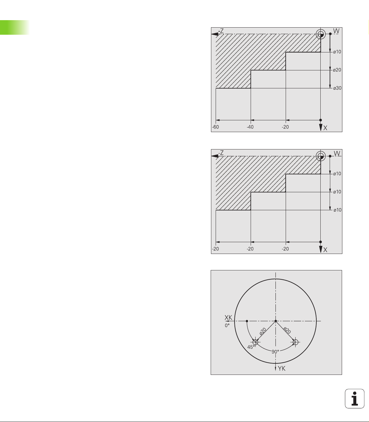
Absolute coordinates
If the coordinates of a position are referenced to the workpiece zero
point, they are referred to as absolute coordinates. Each position on a
workpiece is clearly defined by its absolute coordinates (see figure at
upper right).
Incremental coordinates
Incremental coordinates are always referenced to the last
programmed position. They specify the distance from the last active
position and the subsequent position. Each position on a workpiece is
clearly defined by its incremental coordinates (see figure at center
right).
Polar coordinates
Positions located on the face or lateral surface can either be entered
in Cartesian coordinates or polar coordinates.
When programming with polar coordinates, a position on the
workpiece is clearly defined by the entries for diameter and angle (see
figure at bottom right).
1.4 Axis Designations and Coordinate System
26 1 Introduction and Fundamentals
Page 27
1.5 Machine Reference Points
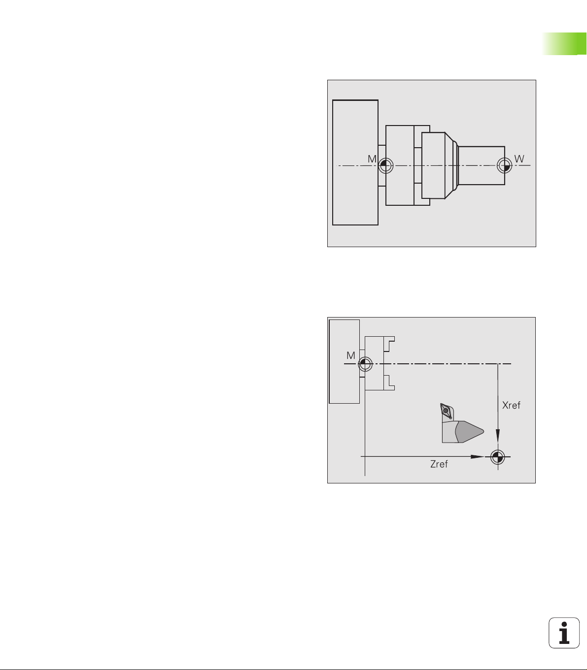
Machine zero point
The point of intersection of the X and Z axes is called the "machine
zero point." On a lathe, the machine zero point is usually the point of
intersection of the spindle axis and the spindle surface. The machine
zero point is designated with the letter "M" (see figure at upper right).
Workpiece zero point
For machining a workpiece, it is easier to reference all input data to a
zero point located on the workpiece. By programming the zero point
used in the workpiece drawing, you can take the dimensions directly
from the drawing, without further calculation. This point is the
"workpiece zero point." The workpiece zero point is designated with
the letter "W" (see figure at center right).
Reference points
Whether the control "forgets" the positions of the machine axes when
it is switched off depends on the position encoders used. If the
positions are lost, you must pass over the fixed reference points after
switching on the MANUALplus. The control knows the exact distance
between these reference marks and the machine zero point (see
figure at lower right).
1.5 Machine Reference Points
HEIDENHAIN MANUALplus 4110 27
Page 28
1.6 Tool Dimensions
MANUALplus requires data on the specific tools for a variety of tasks,
such as positioning the axes, calculating cutting radius compensation
or proportioning of cuts.
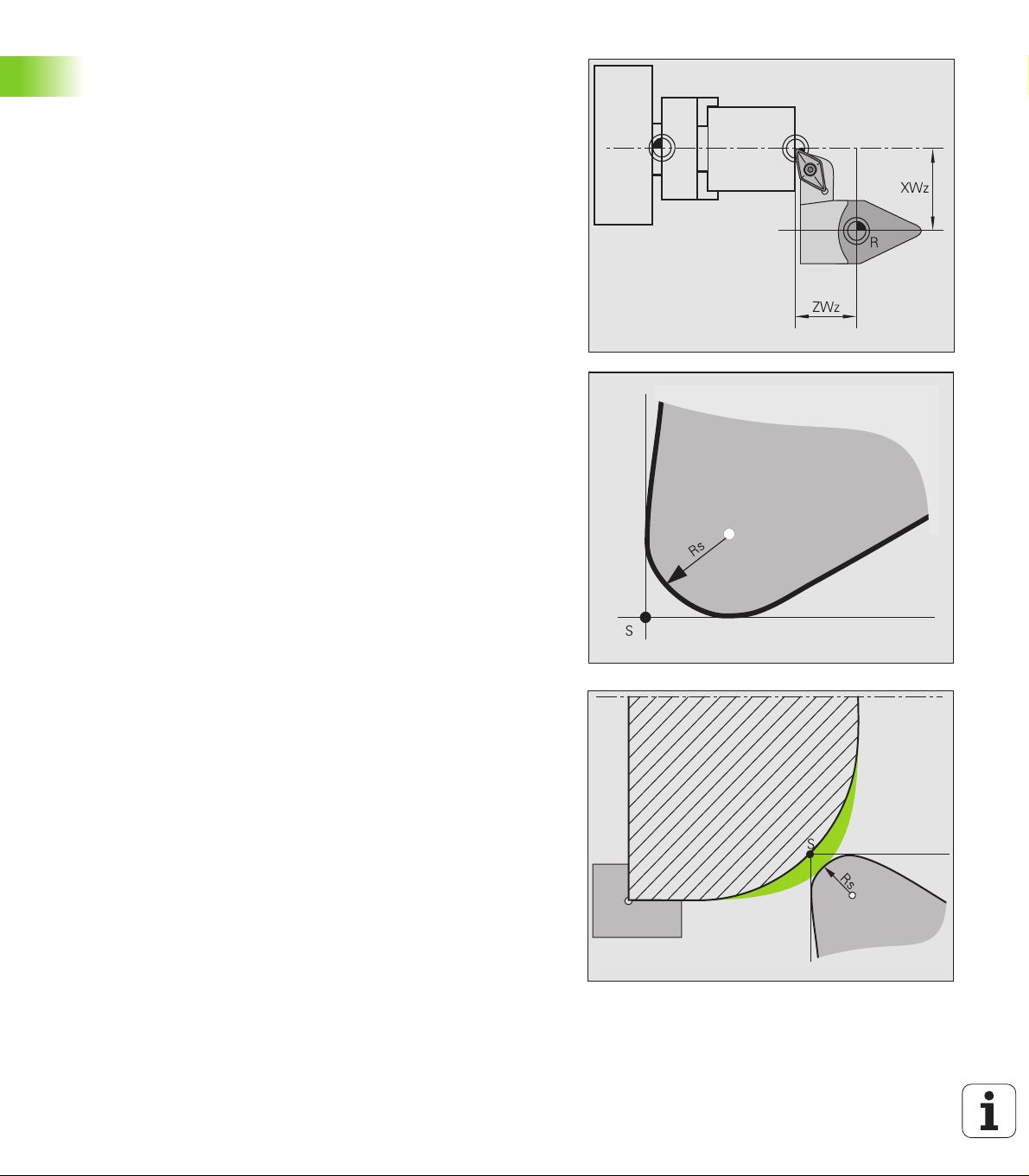
Tool length
All position values that are programmed and displayed are referenced
to the distance between the tool tip and workpiece zero point. Since
the control only knows the absolute position of the tool carrier (slide),
it needs the dimensions XWz and ZWz to calculate and display the
position of the tool tip (see figure at upper right).
1.6 Tool Dimensions
Tool compensation
The tool tip is subjected to wear during machining processes. To
compensate for this wear, MANUALplus uses compensation values
which are managed independent of the values for length. The system
automatically adds the compensation values to the values for length.
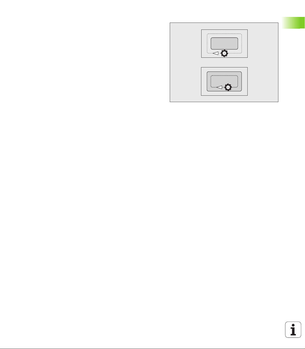
Tool-tip radius compensation (TRC)
The tip of a lathe tool has a certain radius. When machining tapers,
chamfers and radii, this results in inaccuracies which MANUALplus
compensates with its cutting radius compensation function.
Programmed paths of traverse are referenced to the theoretical tool
tip S (see figure at center right). With non-paraxial contours, this will
lead to inaccuracies during machining.
The TRC function compensates this error by calculating a new path of
traverse, the equidistant line (see figure at bottom right).
MANUALplus calculates the TRC for cycle programming. The DIN
programming feature also takes the TRC for clearance cycles into
account. During DIN programming with single paths, you can also
enable/disable TRC.
28 1 Introduction and Fundamentals
Page 29
Milling cutter radius compensation (MCRC)
In milling operations, the outside diameter of the milling cutter
determines the contour. When the MCRC function is not active, the
system defines the center of the cutter as reference point. The MCRC
function compensates for this error by calculating a new path of
traverse, the equidistant line.
1.6 Tool Dimensions
HEIDENHAIN MANUALplus 4110 29
Page 30

Page 31

Basics of Operation
Page 32

2.1 The MANUALplus
Screen
MANUALplus shows the data to be displayed in
windows. Some windows only appear when they are
needed, for example, for typing in entries.
In addition, MANUALplus shows the type of
operation and the soft-key display on the screen.
Each function that appears in a field of the soft-key
row is activated by pressing the soft key directly
below it.
Screen windows displayed
Machine window
Position display, display of machine data, machine
status, etc.
List and program window
Display of program lists, tool lists, parameter lists,
etc. To select specific elements from the list, simply
2.1 The MANUALplus Screen
move the highlight to the desired element with the
arrow keys.
Menu window
Display of menu symbols. This window only
appears on the screen when menu selection is
active.
Input box
For entering the parameters of a cycle, ICP
element, DIN command, etc. You can enter data,
check already programmed data, and edit and
delete data as required. This window is also used to
display data.
Graphic support window
Input data (such as cycle parameters, tool data, etc.)
are explained with graphics. The Circle key allows
you to switch between the help graphics for internal
and external machining.
Simulation window
The simulation window shows a graphic
representation of the contour elements and a
simulation of the tool movements. This enables you
to check cycles, entire cycle programs, and DIN
programs.
ICP contour graphics
Display of the contour during ICP programming.
DIN editing window
Display of the DIN program during DIN
programming. It is superimposed on the "machine
window."
Error window
Display of encountered errors and warnings.
32 2 Basics of Operation
Page 33

2.2 Operation and Data Input
Modes of operation
The active mode of operation is highlighted. MANUALplus
differentiates between the following operating modes:
Machine—with the submodes:
Manual mode (display: "Machine")
Teach-in
Program run
Tool administration (tool management)
Organization
You can switch between the different operating modes using the
Process key. Press the Process key once to activate the operatingmode bar. Select the desired mode of operation using the arrow keys
and press the Process key again to activate it.
The Process key can only be used when the main menu of
the current operating mode is active. You reach the main
menu with Back or with the “Menu” key.
Menu selection
The numerical keypad is used for activating a menu and for entering
data. The menu items are presented as a 9-field box. Each field of this
symbol corresponds to the numerical key that is located at the same
position on the numerical keypad. The functions, cycles, tools, etc. are
displayed as symbols. The meaning of the selected symbol / menu
item is described in the footer.
Press the corresponding numerical key, or move the highlight with the
arrow keys to the symbol on the screen and press the ENTER key.
Soft keys
With some system functions, the available functions are arranged
on several soft-key levels.
Some soft keys work like "toggle switches." A function is active
when the associated field in the soft-key row is highlighted in color.
The setting remains in effect until the function is disabled again.
With functions like Take over position you do not have to enter
values manually. The data are automatically written into the
appropriate input fields.
Data entries are not concluded until the Save or Input finished soft
key has been pressed.
The Back soft key takes you back to the previous operating level.
2.2 Operation and Data Input
HEIDENHAIN MANUALplus 4110 33
Page 34

Data input
Input windows comprise several input fields. You can move the
cursor to the desired input field with the vertical arrow keys. The
function of the selected field is shown in the bottom line of the
window.
Place the highlight on the desired input field and enter the data.
Existing data are overwritten. With the horizontal arrow keys, you can
move the cursor within the input field and place it on the position
where you want to delete, copy or add characters.
To confirm the data you entered in a field, press a vertical arrow key
or the ENTER key.
If there are more input fields than a window can show, a second input
window is used. You will recognize this through the symbol in the
bottom line of the input window. To switch back and forth between
the windows, press the PgUp/PgDn keys.
Data entry is concluded when you press Input finished or
Save.—If you press the Back soft key, entries or changes
2.2 Operation and Data Input
will be lost.
List operations
Cycle programs, DIN programs, tool lists, etc. are displayed as lists.
You can scroll through a list with the arrow keys to check data or to
highlight elements for operations like deleting, copying, editing, etc.
34 2 Basics of Operation
Page 35

Alphanumeric keyboard
Program descriptions, tool descriptions, comments,
etc. are entered with the on-screen alphanumeric
keyboard. You select the desired character with the
arrow keys and confirm the character with ENTER.
You can switch between upper and lower case letters
with the SHIFT button.
To edit existing texts, place the cursor on the desired
position: Press the Up arrow key repeatedly until the
cursor reaches the input line. Then use the horizontal
arrow keys to delete, overwrite or add to the text, as
required.
With the INS key (on the alphanumeric keyboard) you
can determine whether to insert or overwrite
characters. Which mode of the INS key is presently
active (insert mode or overwrite mode) is indicated
below the input line.
Numbers are entered with the data input keypad.
2.2 Operation and Data Input
HEIDENHAIN MANUALplus 4110 35
Page 36

2.3 Error Messages
The appearance and effect of a MANUALplus error
message depend on the current operation.
Direct error messages
The MANUALplus uses direct error messages
whenever immediate error correction is possible and
advisable, for example if the input value of a cycle
parameter exceeds the valid input range. Confirm the
message with ENTER and correct the error (see figure
2.3 Error Messages
to the upper right).
Information of direct error messages:
The error description explains the error that has
occurred.
The error number is needed whenever you contact
the machine manufacturer about a specific error
message.
The time shows you when the indicated error
occurred.
Meaning of the symbols
Warning: The program run / operation continues.
MANUALplus points out the problem.
Error: The program run/operation is stopped. You
must correct the error before being able to continue.
Error display
The control temporarily stores any errors or messages
that appear during system start, operation or program
run, and sets the error symbol in the top line. Using
the Info key, open the error window to view the
messages.
If more error messages have occurred than can be
shown in one screen page of the error window, you
can scroll through the error display with the arrow
keys and PgUp/PgDn to check all messages.
36 2 Basics of Operation
Page 37

Clearing an error message
You can cancel the error message on which the cursor is located with
the "Backspace" key, or cancel all of the error messages with the
"Clear" key.
The error symbol remains set in the top line until all of the errors have
been canceled.
You can exit the error window without clearing any error messages by
pressing Back.
Information in the error message:
The error description explains the error that has occurred.
The error number, level indication (D level, C level) and "OM no."
are needed whenever the supplier needs to be contacted.
The time shows you when the indicated error occurred.
The error class is indicated in the framed field (to the top left of the
message). A message without this field represents a warning.
Background: This message serves as information, or merely a
"small" error has occurred.
Abort: The current operation (execution of a cycle, traverse
command, etc.) was aborted. You can resume operation once the
error has been cleared.
Emergency stop: An error condition has caused all traverse to be
stopped and the abortion of cycle program and DIN program
execution. You can resume operation once the error has been
cleared.
Reset: An error condition has caused all traverse to be stopped
and the abortion of cycle program and DIN program execution.
Switch off the control for a moment, then restart. Contact your
machine manufacturer if the error occurs again.
2.3 Error Messages
System error, internal error
In the unlikely event that a system error or an internal error occurs,
write down all information on the displayed message and inform your
machine manufacturer. You cannot correct these errors. Switch off
the control and restart.
PLC error, PLC status display
Using the soft keys PLC diagnosis and CNC diagnosis, you can
switch between the error information and the PLC window.
The PLC window is used for PLC messages and the PLC diagnosis.
Please refer to your machine manual for more information.
HEIDENHAIN MANUALplus 4110 37
Page 38

Warnings during simulation
If during simulation of a cycle, an entire cycle program
or a DIN program MANUALplus detects problems, it
displays a warning in the soft key to the extreme left
(see figure to the lower right). Press the soft key to
call these messages.
2.3 Error Messages
38 2 Basics of Operation
Page 39

2.4 Explanation of Terms
Cursor: In lists, or during data input, a list item, an input field or a
character is highlighted. This "highlight" is called a cursor. Entries
and operations, like copying, deleting, inserting a new item, etc.,
refer to the current cursor position.
Arrow keys: The cursor is moved with the horizontal and vertical
arrow keys and with the PgUp/PgDn keys.
Page keys: The PgUp/PgDn keys are also called "Page keys."
Navigate: Within a list or an input box, you can move the cursor to
any position you would like to check, change, delete or add to. In
other words, you "navigate" through the list.
Active/ inactive windows, functions, menu items: Of all
windows that are displayed on the screen, only one is active. That
means, any data you type on the keyboard or keypad are entered in
the active window only. In the active window the title bar is shown
in color. In the inactive windows, the title bar appears dimmed.
Inactive function keys or menu keys also appear dimmed.
Menu, menu key: MANUALplus arranges the available functions
and function groups in a 9-field box. This box is called a menu. Each
symbol in the menu is a menu key.
Editing: Editing is changing, deleting and adding to parameters,
commands, etc. within programs, tool data or parameters.
Default value: If the parameters of cycles or DIN commands are
preassigned values, these values are referred to as default values.
These values are used if you do not enter the parameters.
Byte: The capacity of a storage disk is indicated in bytes. Since
MANUALplus features a hard disk, the individual program lengths
are expressed in bytes.
Extension: File names consist of the actual name and the
extension. The name part and the extension part are separated by
".". The extension indicates the type of file. Examples:
„*.NC“DIN programs
„*.NCS“DIN subprograms (DIN macros)
„*.MAS“Machine parameters
2.4 Explanation of Terms
HEIDENHAIN MANUALplus 4110 39
Page 40

Page 41

Machine Mode of Operation
41 3 Machine Mode of Operation
Page 42

3.1 Machine Mode of Operation
The Machine mode of operation includes all functions for machine
setup, workpiece machining, and cycle and DIN program definition.
Machine setup
For preparations like setting axis values (defining workpiece zero
point), measuring tools or setting the protection zone.
Manual operation
Machine a workpiece manually or semi-automatically.
Teach-in
"Teach-in" a new cycle program, change an existing program, or
graphically simulate cycles.
DIN programming
Creating, editing, deleting DIN programs.
Program run
Graphically simulate existing cycle programs or DIN programs and
use them for the production of parts.
With MANUALplus, you produce a part in the usual manner by moving
the axes with the handwheels and jog controls, just like on a
conventional lathe. In most cases, however, it is much more
3.1 Machine Mode of Operation
convenient to use the cycles offered by MANUALplus.
A cycle is a machining step that has already been programmed for
you. This can be any machining operation from a single cut through to
a complex machining task like thread cutting. In any case, a cycle is
always a complete machining step that is immediately executable
once you have defined a few parameters that describe the workpiece
to be machined.
In Manual mode, the cycles that you program are not stored. In
Teach-in mode, each machining step is executed with a cycle and then
stored and integrated into a complete cycle program. You can
subsequently use this cycle program in parts production by repeating
it as often as desired in the Program run mode.
In ICP programming, any contour can be defined using linear/circular
elements and transition elements (chamfers, roundings, undercuts).
The contour descriptions are included in ICP cycles (see “ICP
Contours” on page 242).
The DIN programming feature provides commands for simple
traversing movements, DIN cycles for complex machining tasks,
switching functions, mathematical operations and programming with
variables.
You can either create "independent" programs that already contain all
necessary switching and traversing commands and are executed in
the Program run mode, or program DIN macros that are integrated in
cycles. The commands that you use in a DIN macro depend on the job
at hand. DIN macros support the complete range of commands that is
available for DIN programs.
You can also convert cycle programs to DIN programs. This enables
you to make use of straightforward cycle programming, and then
convert the part program to DIN format for subsequent optimization or
completion.
42 3 Machine Mode of Operation
Page 43

3.2 Switch-On / Switch-Off
Switch-on
In the screen headline, MANUALplus displays the
individual steps that are performed during system
start. When the system has completed all tests and
initializations, it switches to the Machine mode of
operation. The tool display shows the tool that was
last used. Whether a reference run is necessary
depends on the encoders used.
If errors are encountered during system start,
MANUALplus displays the error symbol on the
screen. You can check these error messages as soon
as the system is ready (see “Error Messages” on
page 36).
After system start, MANUALplus
assumes that the tool which was last used
is still inserted in the tool holder. If this is
not the case, you must inform
MANUALplus of the tool change.
Traversing the reference marks
Reference run
Select X reference.
Select Z reference.
Press Cycle START for the control to
traverse the reference marks.
MANUALplus activates the position display and
switches the menu and the soft-key row to the main
menu.
3.2 Switch-On / Switch-Off
Whether a reference run is necessary depends on the
encoders used:
EnDat encoder: Reference run is not necessary.
Distance-coded encoders: The position of the axes
is ascertained after a short reference run.
HEIDENHAIN MANUALplus 4110 43
Page 44

Standard encoder: The axes move to known, machine-based points.
As soon as a reference mark is traversed, a signal is transmitted to
the control. The control knows the distance between the reference
mark and the machine zero point and can now establish the precise
position of the axis.
In case you traverse the reference marks separately for
the X and Z axes, you only traverse in either the X or the
Z axis.
Monitoring EnDat encoders
If EnDat encoders are used, the control saves the axis positions during
switch-off. During switch-on, the MANUALplus compares for each
axis the position during switch-on with the position saved during
switch-off.
If there is a difference, one of the following messages appears:
"Axis was moved after the machine was switched-off."
3.2 Switch-On / Switch-Off
Check the current position and confirm it if the axis was in fact
moved.
"Saved encoder position of the axis is invalid."
This message is correct if the control has been switched on for the
first time, or if the encoder or other control components involved
were exchanged.
"Parameters were changed. Saved encoder position of the axis is
invalid."
This message is correct if configuration parameters were changed.
The cause for one of the above listed messages can also be a defect
in the encoder or control. Please contact your machine supplier if the
problem recurs.
44 3 Machine Mode of Operation
Page 45

Switch-off
Proper switch-off is recorded in the error
log file.
Switch-off
Go to the main level of the Machine
mode of operation.
Press the Switch off soft key.
MANUALplus displays a confirmation request.
Press ENTER to terminate the
control.
Wait until MANUALplus requests you to switch off
the machine.
3.2 Switch-On / Switch-Off
HEIDENHAIN MANUALplus 4110 45
Page 46

3.3 Machine Data
Input and display of machine data
In Manual mode, the machine data for tool, spindle
speed and feed rate are entered in "Set T, S, F ." In
cycle programs the machine data are included in the
cycle parameters, and in DIN programs they are part
of the NC program.
In "Set T, S, F" you also define the "maximum speed"
and the "stopping angle."
3.3 Machine Data
You can store the cutting data (spindle speed, feed
rate) together with the tool data and transfer them
with the S, F from tool soft key (see “Tool Data—
Supplementary Parameters” on page 426).
Machine data display
The machine data display is configurable.
The machine data that appear on your
screen may therefore deviate from the
example shown.
Entering the machine data
Select "Set T, S, F" (only available in
Manual mode).
Define the parameters.
Conclude data input.
Elements of machine data display
Position display X, Z: Distance between tool tip and workpiece
zero point
Letter designating the axis appears in white: Axis "disabled"
Position display C: Position of the C axis
Empty box: C axis is not active
Letter designating the axis appears in white: Axis "disabled"
Distance-to-go display X, Z, C: The distance remaining from the
current position to the target position of the active traversing
command
Distance-to-go Z and protection zone status: Distance-to-go
display and display of status of protective zone monitoring
Spindle utilization: Utilization of the spindle motor relative to the
rated torque
Spindle utilization and maximum speed: Utilization of the
spindle motor and additional display of valid maximum speed
46 3 Machine Mode of Operation
Page 47

Tool call
Elements of machine data display
T display
T number of the inserted tool
Tool compensation values
"T" highlighted in color: Machining of "mirrored contour" active
S display
Symbol of spindle status
Upper field: Programmed value
Lower field: Setting of override control and actual spindle
speed—with position control (M19): spindle position
Gear range (figure beside "S")
"S" highlighted in color: Display applies to driven tool
F display
Symbol of cycle status
Upper field: Programmed value
Lower field: Setting of override control and actual feed rate
3.3 Machine Data
T is the identification letter for the tool data.
Depending on the tool carrier used, "T" is followed by
2 or 4 characters.
One tool holder (e.g. Multifix):
Call: "Tdd"
More than one tool holder (e.g. turret): Call:
„Tddpp“
dd: Position in the tool file (tool list)
pp: Position on the tool carrier (turret location)
In Manual mode, the T number is entered in "Set T, S,
F"—in Teach-in mode, "T" is a cycle parameter.
Power-driven tools
Driven tools are defined in the tool description.
If the active tool is driven, the displayed spindle data
refer to the tool.
The following input parameters refer to spindle 1
when a driven tool is active:
Spindle speed / Constant cutting speed
Maximum speed
Feed per revolution in "Set T, S, F"
Soft keys for "Set T, S, F"
See “Tool compensation” on page 58
See “Setting up Tools” on page 54
Call the tool list—Transfer of T number from the tool
list possible
Transfer of spindle speed and feed rate from the tool
data
On: Feed per minute (mm/min)
Off: Feed per revolution (mm/rev)
On: Constant speed (rpm)
Off: Constant cutting speed (m/min)
HEIDENHAIN MANUALplus 4110 47
Page 48

If a driven tool is active, the spindle speed and speed
limitation refer to the tool.
Your machine documentation provides information on
whether the driven tool can be operated with feed per
revolution.
Tools with more than one cutting edge
If you use special tools with more than one cutting edge, different tool
parameters apply (set-up dimensions, cutting radius, etc.). Enter more
3.3 Machine Data
than one tool definition to define these tools. If "T" is programmed with
four digits (Tddpp), program a new "dd" ("pp" remains the same) when
another cutting edge of the special tool is used.
Tools in different quadrants
Example: The principal tool carrier of your lathe is in front of the
workpiece (standard quadrant). An additional tool holder is behind the
workpiece.
When MANUALplus is configured, it is defined for each tool holder
whether the X dimensions and the direction of rotation of circular arcs
must be mirrored. In the above-mentioned example the additional tool
holder is assigned the attribute "Mirrored."
If this method is used, all machining operations are programmed as
usual—regardless of which tool holder executes the operation. The
simulation also shows all machining operations in the standard
quadrant.
The tools are also described and dimensioned for the standard
quadrant—even if they are inserted in the additional tool holder.
Mirroring does not become effective until the machining of the
workpiece, i.e. when the additional tool holder is executing the
machining operation.
Feed rate
"F" is the identification letter for feed data. Depending on which mode
of the Feed rate soft key is active, data is entered in:
Millimeters per spindle revolution (feed per revolution)
Millimeters per minute (feed per minute).
On the screen, you can tell the type of feed rate from the unit of
measure in the input field.
You can change the feed value with the feed compensation
controller (feed override) (range: 0% to 150%).
48 3 Machine Mode of Operation
Feed symbols (F display) Symbol
Status "Cycle ON"
Cycle or program execution is active.
Status "Cycle OFF"
Cycle or program execution is not
active.
Page 49

Spindle
"S" is the identification letter for spindle data. Depending on which
mode of the Constant speed soft key is active, data is entered in:
Revolutions per minute (constant speed)
Meters per minute (constant cutting speed).
The input range is limited by the maximum spindle speed. You define
the speed limitation in "Set T, S, F", in machine parameters 805/855,
or in DIN programming with the G26 command.
The speed limit remains in effect until a new speed limit value is
programmed.
The speed compensation controller (speed override) allows you to
change the spindle speed (range: 50% to 150%).
The subscript number after the identification letter "S" indicates the
gear range.
If you are machining with a constant cutting speed,
MANUALplus calculates the spindle speed from the
position of the tool tip. The smaller the diameter of the
tip, the higher the spindle speed. The maximum spindle
speed, however, is never exceeded.
The spindle symbols indicate the direction of spindle
rotation as seen from the point of view of the machinist.
Spindle symbols (S display) Symbol
Direction of spindle rotation M3
Direction of spindle rotation M4
Spindle stopped
3.3 Machine Data
Spindle position-controlled (M19)
HEIDENHAIN MANUALplus 4110 49
Page 50

3.4 Machine Setup
The machine always requires a few preparations, regardless of
whether you are machining a workpiece manually or automatically. In
Manual mode the following functions are subitems of the "Setup"
menu item:
Setting the axis values (defining workpiece zero point)
Setting the protection zone
Defining the tool change position
Setting C-axis values
3.4 Machine Setup
Defining the workpiece zero point
Select "Setup."
„Select "Set axis values."
Touch the workpiece zero point (end face).
Define this point as the workpiece zero point Z.
Enter the distance between the tool and the workpiece zero point as
"measuring point coordinate Z."
MANUALplus calculates the "workpiece zero point Z."
Machine zero point Z = workpiece zero point Z
(offset = 0).
Machine zero point X = workpiece zero point X
(offset = 0).
In the graphic support window, MANUALplus illustrates the distance
between the machine zero point and the workpiece zero point (also
referred to as "offset").
If the workpiece zero point is changed, the display values will be
changed accordingly.
If you want to change the workpiece zero point in X, enter
the diameter value as "Meas. pt. coordin. X." The graphic
display shows the distance "Machine zero point X to
workpiece zero point" as a radius value.
50 3 Machine Mode of Operation
Page 51

Setting the protection zone
Whenever the tool is moved, MANUALplus checks whether the
"protection zone" is violated (in the negative Z direction). If it detects
such a violation, it stops the axis movement and generates an error
message.
The graphic support window shows the current setting for the
protection zone:
Distance between machine zero point and protection zone.
"-99999.000" means: Protection zone (in the negative Z direction) is
not monitored.
Setting the protection zone/switching off the monitoring
function
Select "Setup."
Select the function for setting the protection zone.
Move the tool with the jog keys or handwheel until it reaches the
protection zone.
Define this position as protection zone.
3.4 Machine Setup
Enter the position of the protection zone relative to the workpiece zero
point (field: "Meas. pt. coordin.–Z").
Transfer the entered position as protection zone.
Switch off protective zone monitoring.
Display of the status of protective zone monitoring
Display symbol 9 of the machine display shows the current status of
protective zone monitoring (see “Configuration parameters” on
page 435 – control parameter 301).
Protective zone monitoring is not active if the input
window "Set protect. zone" is open.
In DIN programming, protective zone monitoring can be
deactivated with M417 and reactivated with M418.
HEIDENHAIN MANUALplus 4110 51
Protection zone status Symbol
Protective zone monitoring active
Protective zone monitoring not
active
Page 52

Defining the tool change position
With the cycle "Move to tool change position" or the DIN command
G14, the slide moves to the tool change point. Always program the
tool change point as far from the workpiece as possible to avoid
damage to the workpiece during tool change.
Defining the tool change position
Select "Setup."
3.4 Machine Setup
Approach the tool change position.
Move to the tool change point using the jog keys or the handwheel.
Press "Tool change point."
Define this position as tool change point.
The coordinates of the tool change position are entered
and displayed as distance between machine zero point
and tool carrier zero point. As these values are not
displayed, it is advised to approach the tool change point
and then to define the parameters using Take over
position.
52 3 Machine Mode of Operation
Page 53

Setting C-axis values
The zero point for the C axis can be defined as follows:
Defining the zero point of the C axis
Select "Setup."
Press "Set C-axis values."
Position the C axis.
Define the position as the zero point of the C axis.
Enter the zero point shift of the C axis.
Confirm entry for MANUALplus to calculate the zero
point of the C axis.
Delete zero point shift of the C axis.
3.4 Machine Setup
HEIDENHAIN MANUALplus 4110 53
Page 54

3.5 Setting up Tools
MANUALplus offers functions for measuring tools by touching the
workpiece with the tool or by using a touch probe or an optical gauge.
Set the measuring method in machine parameter 6.
If the tool dimensions are already known, you can enter the setup
dimensions directly in the "Tool management" mode of operation.
Finding the tool dimensions by touch-off with the tool
In the tool table, enter the tool you want to measure (see “Tool Data”
on page 418).
3.5 Setting up Tools
Insert the reference tool and enter the T number in
"Set T, S, F."
Turn an end face and define this coordinate as the workpiece zero
point.
Return to "Set T, S, F", insert the tool to be measured
and enter the associated T number.
Activate Measure tool.
Touch the end face with the tool. Enter the value "0" for the "measuring
point coordinate Z" (workpiece zero point).
Save the tool dimensions (the compensation value is
deleted).
Turn a measuring diameter. Enter the diameter value as "measuring
point coordinate X."
Save the tool dimensions (the compensation value is
deleted).
Enter the cutting radius.
Transfer the cutting radius to the tool table.
54 3 Machine Mode of Operation
Page 55

There are several ways to determine tool dimensions. The following
method describes how the dimensions are determined by comparing
a tool with an already measured tool.
The graphic support window shows the details of the tool
measurement process, taking the selected tool type and
tool orientation into account.
3.5 Setting up Tools
HEIDENHAIN MANUALplus 4110 55
Page 56

Finding the tool dimensions by using a touch probe
In the tool table, enter the tool you want to measure (see “Tool Data”
on page 418).
Insert the tool and enter the T number in "Set T, S, F."
Activate Measure tool.
3.5 Setting up Tools
Pre-position the tool for the first direction of measurement.
Press the soft key for this direction (e.g. Z direction).
Press Cycle START. The tool moves in the direction of
measurement. When it contacts the touch probe, the
control calculates and saves the set-up dimensions.
The compensation value is deleted.
Pre-position the tool for the second direction of measurement.
Press the soft key for this direction (e.g. X direction).
Press Cycle START. The tool moves in the direction of
measurement. When it contacts the touch probe, the
control calculates and saves the set-up dimensions.
The compensation value is deleted.
Enter the cutting radius.
Transfer the cutting radius to the tool table.
56 3 Machine Mode of Operation
Page 57

Finding the tool dimensions by using an optical gauge
In the tool table, enter the tool you want to measure (see “Tool Data”
on page 418).
Insert the tool and enter the T number in "Set T, S, F."
Activate Measure tool.
Position the tool at the cross hairs of the optical gauge by using the jog
keys or the handwheel.
Save the tool dimension in Z (the compensation value
is deleted).
Save the tool dimension in X (the compensation value
is deleted).
3.5 Setting up Tools
Enter the cutting radius.
Transfer the cutting radius to the tool table.
HEIDENHAIN MANUALplus 4110 57
Page 58

Tool compensation
The tool compensation in X and Z as well as the special compensation
for recessing tools compensate for wear of the cutting edge.
A compensation value must not exceed 99 mm.
Defining tool compensation
Select "Set T, S, F" (only available in Manual mode).
3.5 Setting up Tools
Press Tool correct.
Select X offset for tool.
The compensation values that you determine per
handwheel are now shown in the "Distance-to-go"
display.
Transfer the compensation value to the tool table.
The T display shows the new compensation value.
The distance-to-go display is cancelled.
Repeat this procedure for the tool compensation Z and the special
compensation.
Deleting tool compensation values
Select "Set T, S, F" (only available in Manual mode).
Select Tool correct.
Cancel the compensation value entered in X.
Repeat this procedure for the tool compensation Z and the special
compensation.
58 3 Machine Mode of Operation
Page 59

Tool life monitoring
If desired, you can have MANUALplus monitor tool
life or the number of parts that are produced with a
specific tool.
The tool life monitoring function adds the times a tool
is traversed at the machine feed rate and counts the
number of finished parts. The count is compared with
the entry in the tool data.
As soon as the tool life expires or the programmed
quantity is reached, MANUALplus generates an error
message and stops program execution after the end
of the program. If you are working with program
repeats (M99 in DIN programs), the system is
stopped after execution of the current repeat.
Tool life monitoring should be carried out for each tool
used.
The tool life monitoring data (type of monitoring,
maximum tool life / remaining tool life and the
maximum number of pieces / remaining number of
pieces) are managed in the tool data. The tool life
monitoring data are also edited and displayed in the
tool data (see “Tool Data— Supplementary
Parameters” on page 426).
Tool life monitoring is enabled and disabled in "Current
parameters—Setup parameters—Tool monitoring."
You must update the data on tool life and number of
pieces in the Tool management mode when you
replace the cutting edge of a tool.
3.5 Setting up Tools
HEIDENHAIN MANUALplus 4110 59
Page 60

3.6 Manual Mode
With manual workpiece machining, you move the axes with the
handwheels or jog controls. You can also use cycles for machining
complex contours (semi-automatic mode). The paths of traverse and
the cycles, however, are not stored.
After switch-on and traversing the reference marks, MANUALplus is
always in Manual mode. This mode remains active until you select
Teach-in or Program run. You can return to Manual mode with the
"Menu" key. "Machine" displayed in the header indicates that you are
in Manual mode.
3.6 Manual Mode
Define the workpiece zero point (see“Machine Setup” on page 50)
and enter the machine data (see “Machine Data” on page 46) before
you start machining.
Tool change
Enter the T number and check the tool parameters.
"T0" does not define a tool. This also means that T0 does not contain
any data on tool length, cutting radius, etc.
Spindle
The spindle speed is entered in "Set T, S, F." To start and stop spindle
rotation, press the buttons on the machine operating panel. Position
the spindle by defining the "Stopping angle A" in the "Set T, S, F"
menu.
Pay attention to the maximum speed (can be defined with
"Set T, S, F").
Handwheel operation
You set the traverse per handwheel increment with the handwheel
resolution selector switch on the machine operating panel.
Jog operation (joystick)
With the jog controls, you can move the axes at the programmed feed
rate or at rapid traverse. The feed rate is programmed in "Set T, S, F."
The rapid traverse speed is set in "Current parameters—Machine
parameters—Feeds."
60 3 Machine Mode of Operation
Page 61

Cycles in Manual mode
Set the spindle speed.
Set the feed rate
Insert tool, define T number and check tool data (T0 is not
permitted).
Approach cycle start point.
Select the cycle and enter cycle parameters.
Graphic control of cycle run.
Run the cycle.
3.6 Manual Mode
HEIDENHAIN MANUALplus 4110 61
Page 62

3.7 Teach-In Mode
In Teach-in mode (cycle mode), you machine a
workpiece step by step with the help of cycles.
MANUALplus "memorizes" how the workpiece was
machined and stores the necessary working steps in
a cycle program, which you can call up again at any
time.
The Teach-in mode can be switched on by soft key
and is displayed in the header.
Each cycle program is given a number and a short
3.7 Teach-In Mode
description. The individual cycles of a cycle program
are listed as blocks and are numbered in ascending
order. The block number has no meaning for the
program run. The cycles are run after each other.
When the cursor is located on a cycle block,
MANUALplus displays the cycle parameters.
The cycle block includes:
Block number
Tool used
Cycle designation
Number of ICP contour or of DIN macro (in [...])
Cycle programming
When creating a new cycle program, you program
each cycle in the following sequence of actions
"Enter—Simulate—Execute—Save." The individual
cycles form the cycle program.
You can change cycle programs by simply editing the
necessary cycle parameters, and delete or add cycles
as required.
When you exit the Teach-in mode or switch off the
machine, the cycle program remains as it was
programmed or edited.
When you call an ICP cycle, MANUALplus displays a
soft key for switching to the ICP contour editor (see
“Editing ICP Contours” on page 243).
DIN macros are programmed in the DIN editor and
then integrated in a DIN cycle. You can call the DIN
editor by soft key when you select the DIN cycle or
when you are in the "Main menu" (see “DIN
Programming” on page 278).
Soft keys
Switch to the "Select cycle programs" function (see
“Program Management” on page 75).
Renumber the block numbers of the cycles.
Call the alphanumeric keyboard to enter or edit the
program description.
Delete the selected cycle.
Copy the cycle parameters into a buffer memory.
When you then press "Add cycle," the data is inserted
(example: copy parameters of roughing cycle into a
finishing cycle).
Edit cycle parameters or cycle mode (the cycle type
cannot be edited).
Insert a new cycle below the highlighted block.
62 3 Machine Mode of Operation
Page 63

3.8 Program Run Mode
In Program run mode, you use cycle programs and
DIN programs for parts production. You cannot
change the programs in this mode. The "graphic
simulation" feature, however, allows you to check the
programs before you run them. MANUALplus also
offers the "Single block" mode with which you can
machine a workpiece, for example, the first of a whole
batch, step by step.
You can start a cycle or DIN program at any desired
block to resume a machining operation after an
interruption.
The program run mode can be switched on with the
soft key and is displayed in the header.
If you press Program run, MANUALplus reads in the
program that was last active in this mode or in the
editing mode. Alternately, you can select another
program with Program list (see “Program
Management” on page 75).
Faulty programs
The MANUALplus checks the programs during
loading. If it detects an error (for example, a
programmed tool that does not appear in the tool list),
it displays the error symbol in the screen headline.
You can then press the "Info" key for detailed
information on the error.
MANUALplus does not translate faulty cycles, but
inserts a "Cycle STOP" at the respective position. All
correct cycles of this program are translated.
3.8 Program Run Mode
Danger of collision!
For programs with faulty cycles, ensure
that the program can be executed without
danger of collision.
Before executing a program
Check the cycles and cycle parameters
MANUALplus displays the cycle program or the DIN
program in the list window. With cycle programs,
the parameters of the cycle on which the cursor is
placed are displayed.
Graphic control
You can monitor program run with the graphic
simulation feature (see “Graphic Simulation” on
page 68).
HEIDENHAIN MANUALplus 4110 63
Page 64

Start block search and program execution
Preconditions for defining a start block:
The MANUALplus must be prepared by the
machine tool builder for the start block function.
The start block function must be activated
(Organization mode of operation: "Current
parameters—NC switches—Settings“ or control
parameter 1)
MANUALplus starts program run from the cursor
position. The starting position is not changed by a
previous graphic simulation.
When selecting the start block in a DIN
program, ensure that the control executes
3.8 Program Run Mode
Program execution
The selected cycle or DIN program is executed as
soon as you press "Cycle START." You can interrupt
machining at any time by pressing "Cycle STOP."
During program run, MANUALplus highlights the
cycle (or DIN block) that is presently being executed.
With cycle programs, the parameters of the cycle
currently being run are displayed in the input window.
The soft keys allow you to influence the program
run—see table.
all commands that define the machine
data (T, S, F) before it reaches the first
traversing command.
Soft keys
Select cycle program or DIN program (see “Program
Management” on page 75).
Cycle program
On: Cycles are run continuously, one after the
other, up to the next tool change.
Off: MANUALplus stops after each cycle. To start
the subsequent cycle, press “Cycle START.”
DIN program
On: Program execution without any interruption.
Off: Stop before command M01.
On: MANUALplus stops after each traverse. To
start the next path of traverse, press Cycle START.
(Recommendation: Single block should be used
together with the basic-block display.)
Off: Cycles / DIN commands are executed without
any interruption.
Input of tool compensation values or additive
correction values.
Switch the graphic simulation on.
On: The traversing and switching commands are
shown in DIN format (base blocks).
Off: Cycle or DIN program is displayed.
The cursor returns to the first block of the cycle
program or DIN program.
64 3 Machine Mode of Operation
Page 65

Entering compensation values during program execution
Compensation values can be entered
during program execution. Entered
values are added to the existing
compensation values and are effective
immediately.
Entering tool compensation values
Activate the tool compensation.
Enter the tool number.
Press Save for the valid
compensation data to be displayed in
the input window.
Enter the compensation values.
Transfer the compensation values
(see “Setting up Tools” on page 54).
3.8 Program Run Mode
Entering additive compensation values
Activate the additive compensation.
Enter the number of the additive compensation.
Press Save for the valid
compensation data to be displayed.
Enter the compensation values.
Press Save.
HEIDENHAIN MANUALplus 4110 65
Page 66

MANUALplus manages 16 additive compensation values as
"parameters." You can edit the additive compensation values in the
"Organization mode of operation—Current parameters." Additive
compensation values need to be activated with "G149" in a DIN
program or a DIN macro.
Setting compensation values with the handwheel
The “Compensation values via handwheel” function is
only available if bit 13 of the configuration code (MP 18
– control configuration) is set.
Entering tool compensation values with the handwheel
3.8 Program Run Mode
Deleting tool compensation values
Interrupt program run with Cycle Stop
Press Tool correct.
Select X offset for tool (or Z offset for tool).
The compensation values that you determine per
handwheel are now shown in the "Distance-to-go"
display.
Transfer the compensation value to the tool table.
The T display shows the new compensation value.
The distance-to-go display is cancelled.
Interrupt program run with Cycle Stop
Select Tool correct.
Select Erase X offset (or Erase Z offset) for the
entered compensation value to be deleted.
66 3 Machine Mode of Operation
Page 67

Program execution in “dry run” mode
The dry run mode is used for fast program execution up to a point at
which machining is to resume. The prerequisites for a dry run are:
The MANUALplus must be prepared by the machine tool builder for
dry run (The function is activated with a keylock switch or a key.)
The Program Run mode must be activated
In dry run, all feed paths (except thread cuts) are traversed at the rapid
rate. You can reduce the traversing speed with the feed rate override.
Do not use the dry run feature for anything other than “cutting air.”
When dry run is activated, the spindle status or spindle speed is
“frozen.” After deactivation of the dry run, the MANUALplus returns
to the programmed feed rates and spindle speeds.
Use the dry run feature only to “cut air.”
3.8 Program Run Mode
HEIDENHAIN MANUALplus 4110 67
Page 68

3.9 Graphic Simulation
The graphic simulation feature enables you to check
the machining sequence, the proportioning of cuts
and the finished contour before actual machining.
In the Manual and Teach-in modes, this function
simulates the execution of a single cycle—in Program
run mode it simulates a complete cycle or DIN
program.
A programmed workpiece blank is displayed in the
simulation graphics. MANUALplus also simulates
machining operations that are executed with a
traversable spindle or the C axis on the face or lateral
surface. This allows you to check the complete
machining process.
3.9 Graphic Simulation
In Manual mode and Teach-in mode, the cycle you are
currently working on is simulated. In the Program run
mode, the simulation of a cycle program always starts
from the cursor position. DIN programs are simulated
from the beginning of the program.
You can choose between wire frame graphics and
cutting path graphics. In addition, the motion
simulation graphics (erasing graphics) is available for
displaying turning operations. It is recommended to
use this graphic check in the "Program run" mode,
since it provides a good overview of the machining
process.
The wire frame graphics is particularly convenient if
you only need a quick overview of the proportioning of
cuts. The path of the theoretical tool tip, however, is
not identical with the contour of the workpiece. This
graphics is therefore not as suitable if you wish to run
a thorough check on the machined contour. In the
CNC, this "falsification" is compensated by the cutting
radius compensation.
The cutting path graphics accounts for the exact
geometry of the tool tip. Here, you can check whether
the contour is machined completely or needs to be
reworked, whether the contour is damaged by the
tool or overlaps are too large. The cutting path
graphics is especially useful for recessing, drilling and
milling operations where the tool shape has an
essential influence on the accuracy of the resulting
workpiece.
68 3 Machine Mode of Operation
Page 69

The motion simulation depicts the workpiece blank
material as a "filled surface" and "machines" it during
simulation by "erasing" the material (erasing graphics).
The tools move at the programmed feed rate
(program-run graphics).
If during running simulation you switch to the motion
simulation, it will not become effective until the
simulation function is restarted.
You can interrupt the motion simulation at any time,
even during simulation of an NC block. The display
below the simulation window indicates the target
position of the current path.
When using the motion simulation for checking
individual cycles, please note that in some cycles the
workpiece blank is not known. The tool movements
will then be displayed, but the machining process will
not be displayed.
3.9 Graphic Simulation
HEIDENHAIN MANUALplus 4110 69
Page 70

Views
Machining operations with traversable spindle or a C
axis can be controlled in the face view or surface view
(under "Extra functions"). The "Lathe, Face or Surface
view" can be displayed as an alternative.
Lathe view
Representation in the X/Z plane.
Face view
Representation in the XK/YK plane. The coordinate
system is based on Cartesian coordinates. The
origin is located in the turning center, with the angle
C=0° positioned on the positive XK axis (see figure
at top right).
Surface view
Representation of the "unrolled lateral surface" (Z/
3.9 Graphic Simulation
CY plane). The coordinate system is based on
Cartesian coordinates. The horizontal line gives the
Z axis, the vertical line the CY axis coordinates (see
figure at bottom right). The upper and lower lines of
this workpiece correspond to the angular positions
C=-180°/+180°, respectively. All drilling and milling
operations are within the range -180° to +180°.
Cycle program or DIN program:
Workpiece simulation is based on the parameter
values for "standard blank" (Current parameters—
Graphic parameters—Standard blank).
Individual cycle or Teach-in
Workpiece simulation is based on the workpiece
section defined by the respective cycle
(expansion in Z and limiting diameter X).
The soft keys "Face view / Surface view"
are only available when a cycle / cycle
program with drilling/milling functions
or a DIN program is active.
You can check the depth of an axial hole
/ milled contour in Lathe view, and the
depth of a radial hole / milled contour in
Face view.
70 3 Machine Mode of Operation
Page 71

Graphic elements
During simulation, MANUALplus shows the following
elements and tool movements in the graphics
window:
Origin of the coordinate system
The workpiece zero point serves as the origin of the
coordinate system.
Contour
At the beginning of a cycle simulation, the
programmed contour of that cycle is depicted in
cyan. In the Teach-in mode, you can display the
preceding contour elements of the cycle program
(function "Display contour elements).
Light dot
The light dot (small white rectangle) represents the
theoretical tool point.
Feed paths
These paths are shown as a continuous green line.
They describe the path of the theoretical tool tip
(also called "wire frame graphics").
Rapid traverse paths
These paths are shown as a broken white line.
Tool tip (cutting edge)
Instead of the light dot, MANUALplus shows the
cutting edge of the tool as a continuous yellow line.
In this case, you can see the real cutting radius,
cutting width and tool-tip position.
With many machining operations, like recessing or
machining an oblique surface or a rounding, you can
check the machining sequence a lot more precisely
by showing the tool tip instead of the light dot.
This graphic display is based on the tool data: If the
control does not have enough data on the tool, it can
only represent the tool tip as a light dot.
Cutting path
In the "cutting path display," MANUALplus shades
the area traversed by the cutting edge of the tool.
You can see the area that will actually be machined,
with the cutting radius, cutting width and tool-tip
position already accounted for. This graphic display
is based on the tool data.
Soft keys
Switch the graphic simulation on.
Magnify, reduce, shift view.
Cycle program
On: Cycles are simulated up to the next tool
change.
Off: MANUALplus stops after each cycle. To
start the subsequent cycle, press Graphic
Continue.
DIN program
On: Program execution without any interruption.
Off: Stop before command M01.
On: MANUALplus stops after each traverse. To
start the simulation of the next path, press
Graphic Continue. (Recommendation: Single
block should be used together with the basic-block
display.)
Off: Cycles / DIN commands are simulated without
any interruption.
The simulation is interrupted.
The simulation is resumed.
Switch on machining simulation.
Switch to the soft-key row with the soft keys for
extra functions.
On: The tool paths are displayed in the cutting path
graphics.
Off: The tool paths are displayed in the wire frame
graphics.
3.9 Graphic Simulation
On: The tool tip is displayed.
Off: The light dot represents the tool tip.
Displays the workpiece blank contour (if
programmed) in Teach-in mode and the contours
defined in every cycle from the beginning of the
program to the cursor position.
HEIDENHAIN MANUALplus 4110 71
Page 72

Displays beneath the graphics window:
Field "N"
Block number of the simulated block.
Fields "X" and "Z"
Target coordinates of the simulated rapid traverse
or feed path.
Field "C"
Spindle angle for positioned spindle (M19) or C axis.
Field "T"
Simulated tool (programmed T number).
Input box
For cycle programs, the cycle designation and the
parameters are displayed.
Warnings
3.9 Graphic Simulation
The simulation feature checks cycle and DIN
programs. Warnings that have occurred are displayed
with the soft key to the extreme left (see “Error
Messages” on page 36). To read the warnings, press
the soft key.
Soft keys
Call the "Time calculation" (see “Time Calculation” on
page 74).
Switch to Face view if you have programmed drilling/
milling cycles for the face.
Switch to Surface view if you have programmed
drilling/milling cycles for the cylindrical surface.
72 3 Machine Mode of Operation
Page 73

Magnify / Reduce
With cycle programs, the simulation feature selects
the area to be simulated in such a way that all paths of
traverse can be illustrated. With DIN programs and
DIN macros, the area to be simulated is taken from
"Current parameters—Graphic parameters—Standard
window size / Standard blank." This is also the case for
the face and lateral-surface views.
MANUALplus offers two menu options, one for
magnifying and reducing the displayed graphic, and
one for isolating a detail:
1 When you press "Zoom," a "red frame" appears
on the screen with which you can select the
detail you wish to isolate. The frame is moved
with the arrow keys, enlarged with PgUp and
reduced with PgDn. To display the selected
detail, press Take over.
The following functions also exist:
Extend view: By reducing the size of the
workpiece, a larger area of the working
space can be displayed. You can use this
function if you would like to isolate an area
of the workpiece with the "red frame," which
is not displayed in the graphics window.
Zoom off: All defined contour areas (the
"workpiece") and the paths of traverse are
shown as large as possible.
Last zoom: Return to the last setting of
Zoom.
3.9 Graphic Simulation
2 You can magnify/reduce the displayed
graphics with the PgUp/PgDn keys, and pan
the detail with the arrow keys. These
functions are always available during
simulation.
With operation 1 you can isolate and display a precise
detail, while operation 2 allows you to pan, magnify or
reduce the graphic spontaneously. It may require
several steps until the desired detail is displayed in the
correct size.
HEIDENHAIN MANUALplus 4110 73
Page 74

3.10 Time Calculation
During simulation, the machining and idle-machine
times are calculated. MANUALplus shows the
machining times under the menu item "Extra
functions—Process times (machining times)."
The machining times, idle times and total times are
shown in the table "Time calculation" (green:
machining times; yellow: idle times). If you are
working with cycle programs, each cycle is shown in
a separate line. In DIN programs, each line represents
the use of a new tool (for each tool call with T).
If there are more table entries than fit on a screen
page, you can call further time data with the arrow
3.10 Time Calculation
keys and PgUp/PgDn. The arrow symbols in the title
bar indicate that more entries are available.
It is also possible to print the time calculation.
74 3 Machine Mode of Operation
Page 75

3.11 Program Management
MANUALplus differentiates between the following
program groups:
Cycle programs
ICP contours
DIN programs
DIN macros
Program information
Program number
The program number (1 to 8 characters) serves to
identify the program within a program group.
Completing zeros are part of the program number.
Program description
You can describe a program by a short text of up to
35 alphanumeric characters. This text is displayed in
the program list.
Date, time
The control stores the time the program was last
changed and displays this in "Sort by date."
Program length
With this information you can estimate the size of a
program. The program length is given in bytes. By
rule of thumb, one cycle or ICP contour element
needs about 165 bytes, and each character of a DIN
program or DIN macro takes up 1 byte.
3.11 Program Management
HEIDENHAIN MANUALplus 4110 75
Page 76

Functions for program management
First select the desired program and then press the corresponding
function key. The selected program is displayed in the "Program
number" field.
Sort program list
The programs of a program group can be listed in alphabetical order
or by date.
Select program
You can select the desired program from the list or enter the
program number.
Activate program
When you press Select program, the control returns to the
previous operating environment. The program that is displayed in
the "Program number" field is activated.
Create new program
Enter the "new program number" and press Select program.
Copy program
3.11 Program Management
The selected program is copied. The copied program then needs to
be assigned a new program number. The other program data is not
changed. Neither are the contents.
Delete program
The selected program is deleted from the system.
Change the program description
With Change text you can call the alphanumeric keyboard to
change a program description or to enter a new one.
If the cursor is located in the "program number" field, you can enter the
number of the desired program. If you do not know the exact program
number, simply enter the "incomplete" number and switch into the
program list with ENTER. The cursor is then located on the first
program number that matches your entry.
When the cursor is in the program list window, you can scroll through
the list to find the desired program. Enter the first character of the
program number for the highlight to jump to the next program that
starts with this number.
You can switch from "Program number" to "Program list" with ENTER
(or the vertical arrow keys). And ENTER (or the horizontal arrow keys)
will take you back to "Program number" again.
If you wish to change a program number, you must copy
the program, assign it a new program number, and then
erase the original program.
76 3 Machine Mode of Operation
Page 77

3.12 Conversion into DIN Format
The "Convert to DIN" function enables you to convert a cycle program
to a DIN program with the same functionality. You can then optimize,
expand such a DIN program, etc.
Conversion into DIN format
Press Cyc.prog. --> DIN.
Select the program to be converted.
Press Create DIN prog.
The generated DIN program has the same program number as the
cycle program.
Should MANUALplus encounter any errors during conversion, it
generates an error message and aborts conversion.
3.12 Conversion into DIN Format
HEIDENHAIN MANUALplus 4110 77
Page 78

3.13 Inch Mode
You can operate MANUALplus in the metric or inch
system (for inch mode, see illustration to the right).
Units in inch mode:
Coordinates, lengths, path data in inches
Feed rate in inch/revolution or inch/min
Cutting speed in ft/min (feet/min)
3.13 Inch Mode
The inch/metric setting is also evaluated for the
displays and entries in tool management and
parameters.
For accuracies for displays and entries, see the table
at right.
The metric/inch setting is selected in the parameter
"Current parameters - NC switches - Settings."
Changed metric/inch settings do not become
effective until the control is restarted.
Cycle programs
Cycle programs are always stored in the metric
system, regardless of whether they were written in
metric or inch mode. If you load a cycle program while
in inch mode, MANUALplus automatically converts
the cycle parameters to inches. The cycle parameters
are then displayed and entered in inches.
Number of decimal places Metric Inch
With coordinate data and path data: 3 4
With compensation values: 3 5
DIN programs that were written in
metric mode may only be executed in
this mode. The same applies for inch
mode. When executing a DIN program,
MANUALplus does not check whether
it was written in inch or metric mode.
Refer to your machine manual if you
want to know whether and how the
handwheel resolution can be set to
inches.
78 3 Machine Mode of Operation
Page 79

Cycle Programming
HEIDENHAIN MANUALplus 4110 79
Page 80

4.1 Working with Cycles
Before you can use the cycles, you must set the workpiece zero point
and ensure that the tools you are going to use are described. The
machine data (tool, feed rate, spindle speed) are entered with the
other cycle parameters in Teach-in mode. In Manual mode, you must
program these machine data before calling a cycle.
Define the individual cycles as follows:
Position the tool tip with the handwheel or the jog keys to the
starting point of the cycle (only in Manual mode).
Select and program a cycle.
Graphically test the cycle.
Execute the cycle.
Save the cycle (only in Teach-in mode).
4.1 Working with Cycles
Starting point of cycles
In Manual mode, cycles are executed from the "current tool position."
In Teach-in mode, you enter the starting point as one of the
parameters. MANUALplus moves to this position in rapid traverse by
the shortest path (diagonal) before executing the cycle.
Danger of collision!
If the tool cannot approach the next starting point on the
shortest path without colliding with the workpiece, you
must define an auxiliary position with the "Rapid traverse
positioning" cycle.
Cycle transitions
Finishing cycles in expanded mode are interrupted at the contour end
point. This enables you to sequentially link several finishing cycles and
thus finish a selected part of the contour in a single uninterrupted cut.
MANUALplus, however, knows only the contour area of the cycle that
is presently being machined. After finishing this contour area, the tool
is positioned for a subsequent horizontal contour element. If the
subsequent element is not horizontal, the tool is positioned to the
contour starting point before the defined contour area is finished. All
positioning is done at feed rate speed.
80 4 Cycle Programming
Page 81

Help graphics
The functionalities and parameters of the cycles are illustrated in the
graphic support window. These graphics usually show an external
machining operation. The Circle key allows you to switch to the help
graphics for internal machining, and
to switch between the help graphics for internal and
external machining.
Elements used in the graphic support window:
Broken line: Rapid traverse path
Continuous line: Feed path
Dimension line with arrow head on one side: "Directional
dimension"—the algebraic sign defines the direction.
Dimension line with arrow head on both sides: "Absolute
dimension"—the algebraic sign has no effect.
DIN macros
You can integrate DIN macros in cycle programs. Make sure that the
DIN macros do not contain any zero point shifts.
Danger of collision!
Cycle programming: With DIN macros, the zero point
shift is reset at the end of the cycle. Therefore, do not use
any DIN macros with zero point shifts in cycle
programming.
4.1 Working with Cycles
Graphical test run (simulation)
Before executing a cycle, you can graphically test the contour details
and the machining sequence (see “Graphic Simulation” on page 68).
Cycle keys
A programmed cycle is not executed until Cycle START is pressed.
Cycle STOP interrupts a running program. With thread cutting, the
current cut will be completed before cycle execution is interrupted.
During a cycle interruption you can:
Resume cycle execution with "Cycle START." The control will always
resume execution of the cycle at the point of interruption—even if
you have moved the axes in the meantime.
Move the axes using the jog keys or handwheels.
Terminate the machining process with the Cancel soft key.
HEIDENHAIN MANUALplus 4110 81
Page 82

Switching functions (M functions)
Whether switching functions are triggered automatically or must be
commanded manually depends on your specific machine.
MANUALplus generates all switching functions that are necessary for
running a cycle.
The direction of spindle rotation must be defined in the tool
parameters. Using the tool parameters, the cycles generate spindle
trigger functions (M3 or M4).
Your machine manual provides further information on
automatically triggered switching functions.
Comments
You may assign a comment to an existing cycle. The comment is
4.1 Working with Cycles
inserted in brackets "[...]" below the cycle.
Adding or editing comments
Create/select a cycle.
Press the Change text soft key.
Enter the comment with the on-screen alphanumeric keyboard.
Transfer the comment.
82 4 Cycle Programming
Page 83

Cycle menu
The main menu shows the cycle groups. Once a cycle
group has been selected, the soft keys for the
individual cycles appear.
You can use ICP cycles for complex contours, and
DIN macros for technologically sophisticated
machining operations (see “ICP Contours” on
page 242 and “DIN Programming” on page 278). In
cycle programs, the numbers of the ICP contours or
DIN macros are at the end of the line of the cycle.
Some cycles offer optional parameters. That means,
specific contour elements will only be machined if you
set the corresponding parameters. The identification
letters for optional parameters and parameters that
are preassigned default values are displayed in gray.
The following parameters are only required in Teach-
in mode:
Starting point X, Z
Machine data S, F and T
4.1 Working with Cycles
Cycle groups Menu key
Workpiece blank
Define standard workpiece blank or workpiece
blank with ICP.
Single cuts
Position at rapid traverse, linear and circular single
cuts, chamfers, and rounding arcs.
Roughing cycles, longitudinal/transverse
Roughing and finishing cycles for turning and facing.
Recessing and recess-turning cycles
Cycles for recessing, contour recessing, undercuts
and parting.
Thread cutting
Thread cycles, relief turns and thread repair.
Drilling
Drilling cycles and patterns for face and lateralsurface machining.
Milling
Milling cycles and patterns for face and lateralsurface machining.
DIN macros
Integrate program sections written in DIN format
into the cycle program.
HEIDENHAIN MANUALplus 4110 83
Page 84

Soft keys in cycle programming
Depending on the type of cycle, you define the
functions for the cycle by soft key. The table to the
right lists the soft keys used in cycle programming.
4.1 Working with Cycles
Soft keys in cycle programming
Call the ICP editor.
Approach the tool change position.
Activate spindle positioning (M19).
On: Tool returns to the cycle start point.
Off: Tool remains at cycle end position.
Linear hole pattern on face or lateral surface.
Circular hole pattern on face or lateral surface.
On: Rework existing thread.
Off: Cut new thread.
Repeat the last thread cut.
Call the "Tool list." You can transfer the T number from
the tool list.
Transfer the actual position X, Z.
Transfer the spindle speed and feed rate from the tool
data.
On: Constant speed (rpm)
Off: Constant cutting speed (m/min)
On: Internal thread
Off: External thread
Transfer entered/changed values.
Cancel the current dialog.
84 4 Cycle Programming
Page 85

4.2 Workpiece Blank Cycles
The workpiece blank cycles describe the
workpiece blank and the setup used. The
workpiece blank cycles do not influence
the machining process.
This information is evaluated during the
simulation of the machining process.
4.2 Workpiece Blank Cycles
Workpiece blank Symbol
Blank—bar/tube
Define the standard blank.
ICP workpc. blank contour
Define workpiece blank contours with ICP.
HEIDENHAIN MANUALplus 4110 85
Page 86

Blank—bar/tube
Select the function for defining a workpiece blank.
Select "Blank—bar/tube."
The cycle describes the workpiece blank and the setup used. This
information is evaluated during the simulation.
Cycle parameters
X outside diameter
Z length—including transverse allowance and clamping range
I inside diameter for workpiece blank "tube"
4.2 Workpiece Blank Cycles
K right edge (transverse allowance)
B clamping range
J type of clamping
0: Not clamped
1: Externally clamped
2: Internally clamped
86 4 Cycle Programming
Page 87

ICP workpc. blank contour
Select the function for defining a workpiece blank.
Select "ICP workpiece blank contour."
The cycle integrates the workpiece blank defined with ICP and
describes the setup used. This information is evaluated during the
simulation.
Cycle parameters
X clamping diameter
Z clamping position
B clamping range
J type of clamping
0: Not clamped
1: Externally clamped
2: Internally clamped
N ICP contour number
4.2 Workpiece Blank Cycles
HEIDENHAIN MANUALplus 4110 87
Page 88

4.3 Single Cut Cycles
In the single cut cycles you position the
tool in rapid traverse, perform linear or
circular cuts, machine chamfers or
rounding arcs, and enter M functions.
4.3 Single Cut Cycles
Single cuts Symbol
Rapid traverse positioning
Approach the tool change position
Linear machining, longitudinal/transverse
Single longitudinal/transverse cut.
Linear machining at angle
Single oblique cut.
Circular machining
Single circular cut (for cutting direction, see
menu key).
Machine a chamfer.
Machine a rounding.
Call an M function.
88 4 Cycle Programming
Page 89

Rapid traverse positioning
Call the single-cut menu.
Select the "Rapid traverse positioning" cycle.
The tool moves at rapid traverse from the starting point to the target
point.
Cycle parameters
X, Z starting point
X2, Z2 target point
T tool number
4.3 Single Cut Cycles
HEIDENHAIN MANUALplus 4110 89
Page 90

Approach the tool change position
Call the single-cut menu.
Select the "Rapid traverse positioning" cycle.
Activate the T-Change approach function
4.3 Single Cut Cycles
The tool moves at rapid traverse from the current position to the tool
change position (see “Defining the tool change position” on page 52).
Cycle parameters
Q sequence—default: 0
0: Diagonal path of traverse
1: First X, then Z direction
2: First Z, then X direction
3: X direction only
4: Z direction only
T tool number: After reaching the tool change position,
MANUALplus switches to the tool indicated in "T."
90 4 Cycle Programming
Page 91

Linear machining, longitudinal
Call the single-cut menu.
Select the "Longitudinal linear machining" cycle.
With return soft key:
Off: When the cycle is completed, the tool remains at
the cycle end position.
On: Tool returns to the starting point.
Longitudinal linear machining
The tool moves from the starting point to the contour end point at the
programmed feed rate and remains at the cycle end position.
Contour linear, longitudinal ("With return")
The tool approaches the workpiece, executes the longitudinal cut and
returns to the starting point at the end of cycle (see figures at right).
Cycle parameters
X, Z starting point
X1 contour starting point
Z2 contour end point
T tool number
S spindle speed / cutting speed
F feed per revolution
Cycle run (if "With return" is active)
1 Move from X, Z to contour starting point X1.
2 Move to contour end point Z2 at programmed feed rate.
3 Retract and return to starting point on paraxial path.
4.3 Single Cut Cycles
HEIDENHAIN MANUALplus 4110 91
Page 92

Linear machining, transverse
Call the single-cut menu.
Select the "Transverse linear machining" cycle.
With return soft key:
4.3 Single Cut Cycles
Transverse linear machining
The tool moves from the starting point to the contour end point at the
programmed feed rate and remains at the cycle end position.
Contour linear, transverse ("With return")
The tool approaches the workpiece, executes the transverse cut and
returns to the starting point at the end of cycle (see figures at right).
Cycle parameters
X, Z starting point
Z1 starting point of contour (if "With return" is active)
X2 contour end point
T tool number
S spindle speed / cutting speed
F feed per revolution
Cycle run (if "With return" is active)
1 Move from X, Z to contour starting point Z1.
2 Move to contour end point X2 at programmed feed rate.
3 Retract and return to starting point on paraxial path.
Off: When the cycle is completed, the tool remains at
the cycle end position.
On: Tool returns to the starting point.
92 4 Cycle Programming
Page 93

Linear machining at angle
Call the single-cut menu.
Select the "Linear machining at angle" cycle.
With return soft key:
Off: When the cycle is completed, the tool remains at
the cycle end position.
On: Tool returns to the starting point.
Linear machining at angle
MANUALplus calculates the target position and moves the tool on a
straight line from the starting point to the target position at the
programmed feed rate. When the cycle is completed, the tool remains
at the cycle end position.
Contour linear, at angle ("With return")
MANUALplus calculates the target position. The tool then approaches
the workpiece, executes the linear cut and returns to the starting point
at the end of cycle (see figures at right). Cutter radius compensation is
taken into account.
Cycle parameters
X, Z starting point
X1, Z1 starting point of contour (if "With return" is active)
X2, Z2 contour end point
A starting angle—range: –180° < A < 180°
T tool number
S spindle speed / cutting speed
F feed per revolution
Parameter combinations for defining the target point:
X2, Z2
X2, A
Z2, A
Cycle run (if "With return" is active)
1 Calculate the target position.
2 Move on a straight line from X, Z to contour starting point X1, Z1.
3 Move to target position at programmed feed rate.
4 Retract and return to starting point on paraxial path.
4.3 Single Cut Cycles
HEIDENHAIN MANUALplus 4110 93
Page 94

Circular machining
Call the single-cut menu.
Select the "Circular machining cycle" (clockwise).
Select the "Circular machining cycle"
(counterclockwise).
4.3 Single Cut Cycles
With return soft key:
Off: When the cycle is completed, the tool remains at
the cycle end position.
On: Tool returns to the starting point.
Circular machining
The tool moves in circular arc from the starting point to the contour
end point at the programmed feed rate and remains at the cycle end
position.
Contour circular ("With return")
The tool approaches the workpiece, executes the circular cut and
returns to the starting point at the end of cycle. Cutter radius
compensation is taken into account (see figures at right).
Cycle parameters
X, Z starting point
X1, Z1 starting point of contour (if "With return" is active)
X2, Z2 contour end point
R radius of rounding
T tool number
S spindle speed / cutting speed
F feed per revolution
Cycle run (if "With return" is active)
1 Move on paraxial path from X, Z to contour starting point X1, Z1.
2 Move in circular arc to contour end point X2, Z2 at programmed
feed rate.
3 Retract and return to starting point on paraxial path.
94 4 Cycle Programming
Page 95

Chamfer
Call the single-cut menu.
Select the "Chamfer" cycle.
With return soft key:
Off: When the cycle is completed, the tool remains at
the cycle end position.
On: Tool returns to the starting point.
Chamfer
The cycle produces a chamfer that is dimensioned relative to the
corner of the workpiece contour. When the cycle is completed, the
tool remains at the cycle end position.
Contour chamfer ("With return")
The tool approaches the workpiece, machines the chamfer that is
dimensioned relative to the corner of the workpiece contour and
returns to the starting point at the end of cycle. Cutter radius
compensation is taken into account (see figures at right).
Cycle parameters
X, Z starting point
X1, Z1 contour corner
A starting angle: Angle of the chamfer, range: 0°< A < 90°
I, K chamfer width (in X, Z)
J element position (see graphic support window)—default: 1
Position is relative to X1, Z1
Algebraic sign determines cutting direction
T tool number
S spindle speed / cutting speed
F feed per revolution
Parameter combinations for defining the chamfer:
I (45° chamfer)
K (45° chamfer)
I, K
I, A
K, A
Cycle run (if "With return" is active)
1 Calculate starting point and end point of chamfer.
2 Move on paraxial path from X, Z to starting point of chamfer.
3 Move to end point of chamfer at programmed feed rate.
4 Retract and return to starting point on paraxial path.
4.3 Single Cut Cycles
HEIDENHAIN MANUALplus 4110 95
Page 96

Rounding
Call the single-cut menu.
Select the "Rounding" cycle.
With return soft key:
4.3 Single Cut Cycles
Rounding
The cycle produces a rounding that is dimensioned relative to the
corner of the workpiece contour. When the cycle is completed, the
tool remains at the cycle end position.
Contour rounding ("With return")
The tool approaches the workpiece, machines the rounding that is
dimensioned relative to the corner of the workpiece contour and
returns to the starting point at the end of cycle. Cutter radius
compensation is taken into account (see figures at right).
Cycle parameters
X, Z starting point
X1, Z1 contour corner
R rounding: Radius of rounding
I, K chamfer width (in X, Z)
J element position (see graphic support window)—default: 1
Position is relative to X1, Z1
Algebraic sign determines cutting direction
T tool number
S spindle speed / cutting speed
F feed per revolution
Cycle run (if "With return" is active)
1 Calculate starting point and end point of rounding.
2 Move on paraxial path from X, Z to starting point of rounding.
3 Move in circular arc to end point of rounding at programmed feed
rate.
4 Retract and return to starting point on paraxial path.
Off: When the cycle is completed, the tool remains at
the cycle end position.
On: Tool returns to the starting point.
96 4 Cycle Programming
Page 97

M functions
Machine commands (M functions) are not executed until Cycle START
has been pressed. For the meaning of the M functions, refer to your
machine manual (see “M Functions” on page 408).
M function
Call the single-cut menu.
Select "M function."
Enter the number of the M function.
Conclude entry.
Press Cycle START.
Spindle stop M19 (spindle positioning)
4.3 Single Cut Cycles
Call the single-cut menu.
Select "M function."
Switch M19 on.
Enter the stopping angle.
Conclude entry.
Press Cycle START.
HEIDENHAIN MANUALplus 4110 97
Page 98

4.4 Roughing Cycles
Roughing cycles rough and finish simple
contours in "basic mode" and complex
contours in "expanded mode."
With ICP cutting cycles, you can
machine contours defined with ICP (see
“Editing ICP Contours” on page 243).
Proportioning of cuts: MANUALplus
4.4 Roughing Cycles
Cutting and infeed directions for roughing cycles
MANUALplus automatically determines the cutting
and infeed directions from the cycle parameters.
Basic mode: The parameters for starting point X, Z
(Manual mode: current tool position) and contour
starting point X1 / contour end point Z2 determine
these directions.
Expanded mode: The parameters for contour
starting point X1, Z1 and contour end point X2, Z2
determine these directions.
ICP cycles: The parameters for contour starting
point X, Z (Manual mode: current tool position) and
starting point of the ICP contour determine these
directions.
calculates an infeed that is <= infeed
depth P. An "abrasive cut" is avoided.
Oversizes: In "expanded" mode.
Cutter radius compensation: Active.
Safety clearance after each step:
Basic mode: 1 mm
Expanded mode: The safety
clearance is set separately for internal
and external machining under
"Current parameters—Machining—
Safety distances."
Roughing cycles Symbol
Roughing, longitudinal/transverse
Roughing and finishing cycle for simple
contours
Plunge-cutting, longitudinal/transverse
Roughing and finishing cycle for simple
contours
ICP contour-parallel, longitudinal/
transverse
Roughing and finishing cycle for any type of
contour
ICP roughing, longitudinal/transverse
Roughing and finishing cycle for any type of
contour
98 4 Cycle Programming
Page 99

Tool position
It is important that you observe the tool positions (starting point X, Z)
before executing any of the roughing cycles in expanded mode.
However, they also apply for all cutting and infeed directions as well
as for roughing and finishing (see examples of linear cycles in figures
at right).
The starting point must not be located in the shaded area.
The area to be machined starts at the starting point X, Z if the tool is
positioned before the contour area. MANUALplus will otherwise
only machine the contour area defined.
If the starting point X, Z for internal machining is located above the
turning center, only the contour area defined will be machined.
(A = contour starting point X1, Z1; E = contour end point X2, Z2)
Contour elements
Contour elements in roughing cycles
Basic mode
Machining a rectangular area
Expanded mode
Oblique cut at contour start
4.4 Roughing Cycles
Expanded mode
Oblique cut at contour end
Expanded mode
Oblique cuts at contour start and end with
angles > 45°
Expanded mode
One oblique cut (by entering the starting
point of contour, end point of contour and
starting angle)
HEIDENHAIN MANUALplus 4110 99
Page 100

Contour elements in roughing cycles
Expanded mode
Rounding
Expanded mode
Chamfer (or rounding) at contour end
4.4 Roughing Cycles
Basic mode
Machining with descending contour
Basic mode
Oblique cut at contour end
Expanded mode
Rounding in contour valley (in both corners)
Expanded mode
Chamfer (or rounding) at contour start
Expanded mode
Chamfer (or rounding) at contour end
100 4 Cycle Programming
 Loading...