


hatcocorp.com
Reg ine! |
|
(see page 2) |
GLO-RITE® |
S'inscrire en ligne! |
|
(voir page 10) |
|
|
Display Lights |
|
Tubes d'Éclairage |
|
HL Series • Série HL |
Installation and Operating Manual |
|
Manuel d'installation et d'utilisation |
|
|
P/N 07.04.295.00 |
WARNING
Do not operate this equipment unless you have read and understood the contents of this manual! Failure to follow the instructions contained in this manual may result in serious injury or death. This manual contains important safety information concerning the maintenance, use, and operation of this product. If you’re unable to understand the contents of this manual, please bring it to the attention of your supervisor. Keep this manual in a safe location for future reference.
ADVERTENCIA
No opere este equipo al menos que haya leído y comprendido el contenido de este manual! Cualquier falla en el seguimiento de las instrucciones contenidas en este manual puede resultar en un serio lesión o muerte. Este manual contiene importante información sobre seguridad concerniente al mantenimiento, uso y operación de este producto. Si usted no puede entender el contenido de este manual por favor pregunte a su supervisor. Almacenar este manual en una localización segura para la referencia futura.
AVERTISSEMENT
Ne pas utiliser cet équipement sans avoir lu et compris le contenu de ce manuel ! Le non-respect des instructions contenues dans ce manuel peut entraîner de graves blessures ou la mort. Ce manuel contient des informations importantes concernant l'entretien, l'utilisation et le fonctionnement de ce produit. Si vous ne comprenez pas le contenu de ce manuel, veuillez le signaler à votre supérieur. Conservez ce manuel dans un endroit sûr pour pouvoir vous y référer plus tard.
Français = p 10
© 2014 Hatco Corporation
CONTENTS |
|
English |
Important Owner Information .............................................. |
2 |
Introduction........................................................................... |
2 |
Important Safety Information............................................... |
3 |
Model Description................................................................. |
4 |
Model Designation................................................................ |
4 |
Specifications........................................................................ |
4 |
Electrical Rating Chart ....................................................... |
4 |
Dimensions......................................................................... |
5 |
Installation ............................................................................. |
6 |
General............................................................................... |
6 |
Suspension mounting ......................................................... |
6 |
adjustable angle Bracket mounting.................................... |
6 |
Electrical Information .......................................................... |
6 |
Operation............................................................................... |
7 |
General............................................................................... |
7 |
Maintenance .......................................................................... |
7 |
General............................................................................... |
7 |
Daily Cleaning .................................................................... |
7 |
Replacing a Display Light Bulb........................................... |
7 |
Troubleshooting Guide ........................................................ |
8 |
Options and Accessories..................................................... |
8 |
Limited Warranty................................................................... |
9 |
Authorized Parts Distributors ............................ |
Back Cover |
IMPORTANT OWNER INFORMATION
Record the model number, serial number, voltage, and purchase date of the unit in the spaces below (specification label located on the front of the unit). Please have this information available when calling Hatco for service assistance. model No. ________________________________________
Serial No. ________________________________________
Voltage __________________________________________
Date of Purchase __________________________________
Register your unit!
Completing online warranty registration will prevent delay in obtaining warranty coverage. access the Hatco website at www.hatcocorp.com, select the Parts & Service pull-down menu, and click on “Warranty Registration”.
Business |
8:00 am to 5:00 Pm Central Standard Time (CST) |
|||
Hours: |
||||
|
(Summer Hours: June to September— |
|||
|
8:00 am to 5:00 |
Pm |
CST monday–Thursday |
|
|
8:00 am to 2:30 |
Pm |
CST Friday) |
|
Telephone: 800-558-0607; 414-671-6350 |
||||
e-mail: |
partsandservice@hatcocorp.com |
|||
Fax: |
800-690-2966 |
(Parts and Service) |
||
|
414-671-3976 |
(International) |
||
24 Hour 7 Day Parts and Service
Assistance available in the United States and Canada by calling 800-558-0607.
additional information can be found by visiting our web site at www.hatcocorp.com.
INTRODUCTION
Hatco Glo-Rite® Display Lights are durable and effective light strips ideal for use in food preparation, holding and display areas.
The lights are made of extruded aluminum housings with bright annealed reflectors for maximum brightness and feature shatter-resistant incandescent lights. Each unit comes equipped for mounting and electrical hook-up along with a Power I/O (on/off) switch for operator control.
Hatco Display Lights are products of extensive research and field testing. The materials used were selected for maximum durability, attractive appearance, and optimum performance. Every unit is inspected and tested thoroughly prior to shipment. This manual provides the installation, safety, and operating instructions for Display Lights. Hatco recommends all installation, operating, and safety instructions appearing in this manual be read prior to installation or operation of a unit.
Safety information that appears in this manual is identified by the following signal word panels:
|
WARNING |
ation which, if not |
|
WARNING indicate |
|
|
|
avoided, could result in death or serious injury. |
|||
|
|
|
|
|
CAUTION |
|
|
CAUTION indicates |
a hazardous |
situation which, if not |
|
avoided, could result in minor or moderate injury. |
|||
|
NOTICE |
|
|
NOTICE is used to address practices not related to personal |
|||
injury. |
|
|
|
2 |
Form No. HLm-0214 |
|
|
IMPORTANT SAFETY INFORMATION |
English |
Read the following important safety information before using this equipment to avoid serious injury or death and to avoid damage to equipment or property.
WARNING
ELECTRIC SHOCK HAZARD:
• Unit must be installed by a qualified electrician. Installation must conform to all local electrical codes. Installation by unqualified personnel will void unit warranty and may lead to electric shock or burn, as well as damage to unit and/or its surroundings.
• Consult a licensed electrical contractor for proper electrical installation conforming to local electrical codes and the National Electrical Code (N.E.C.).
• Turn OFF power at fused disconnect switch/circuit breaker and allow unit to cool before performing any cleaning, adjustments, or maintenance.
• DO NOT submerge or saturate with water. Unit is not waterproof. Do not operate if unit has been submerged or saturated with water.
• Do not clean unit when it is energized or hot.
• Unit is not weatherproof. Locate unit indoors where ambient air temperature is a minimum of 70°F (21°C).
• Do not steam clean or use excessive water on the unit.
• This unit is not “jet-proof” construction. Do not use jetclean spray to clean this unit.
• This unit must be serviced by qualified personnel only. Service by unqualified personnel may lead to electric shock or burn.
• Use only Genuine Hatco Replacement Parts when service is required. Failure to use Genuine Hatco Replacement Parts will void all warranties and may subject operators of the equipment to hazardous electrical voltage, resulting in electrical shock or burn. Genuine Hatco Replacement Parts are specified to operate safely in the environments in which they are used. Some aftermarket or generic replacement parts do not have the characteristics that will allow them to operate safely in Hatco equipment.
FIRE HAZARD: Locate unit the correct distance from combustible walls and materials. If safe distances are not maintained, discoloration or combustion could occur.
WARNING
EXPLOSION HAZARD: Do not store or use gasoline or other flammable vapors or liquids in the vicinity of this or any other appliance.
Make sure all operators have been instructed on the safe and proper use of the unit.
This unit is not intended for use by children or persons with reduced physical, sensory, or mental capabilities. Ensure proper supervision of children and keep them away from the unit.
Use only light bulbs that meet or exceed National Sanitation Foundation (NSF) standards and are specifically designed for food holding areas. Breakage of light bulbs not specially-coated could result in personal injury and/or food contamination.
This unit has no “user-serviceable” parts. If service is required on this unit, contact an Authorized Hatco Service Agent or contact the Hatco Service Department at 800-558-0607 or 414-671-6350; fax 800-690-2966; or International fax 414-671-3976.
CAUTION
Standard and approved manufacturing oils may smoke up to 30 minutes during initial startup. This is a temporary condition. Operate unit without food product until smoke dissipates.
NOTICE
Use non-abrasive cleaners and cloths only. Abrasive cleaners and cloths could scratch finish of unit, marring its appearance and making it susceptible to soil accumulation.
Form No. HLm-0214 |
3 |
|
MODEL DESCRIPTION |
English |
All Models |
|
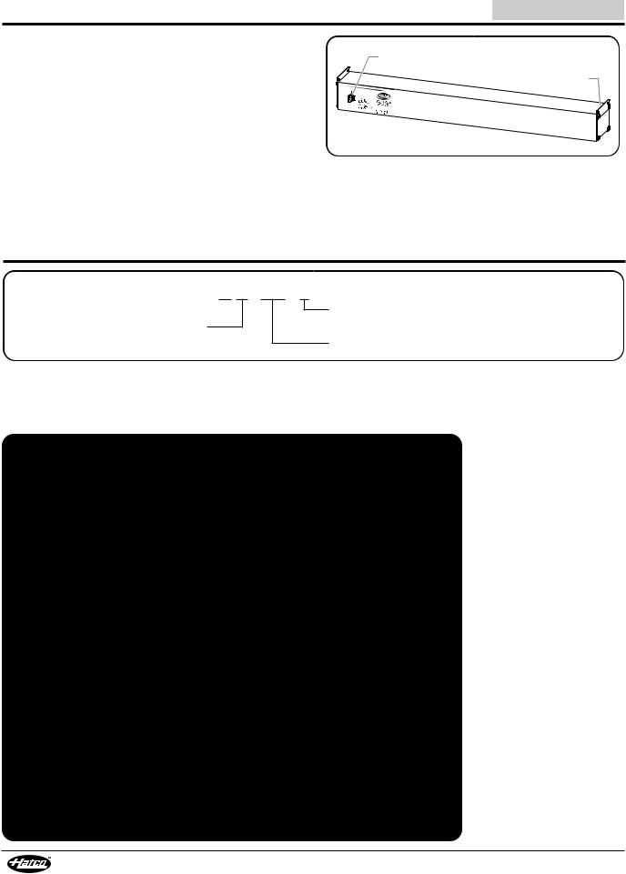
Glo-Rite® Display Lights are specially designed to give long |
Power I/O |
lasting, trouble-free service. The lights are made of extruded |
(on/off) Switch |
aluminum housings and feature bright annealed reflectors for |
Suspension |
maximum brightness. Each unit comes equipped for mounting |
Bracket |
|
|
and electrical hook-up along with a Power I/O (on/off) switch |
|
for operator control. |
|
models are available in lengths from 18" (457 mm) to 72" |
|
(1829 mm) and are available with additional lamp assemblies |
|
for greater illumination. an adjustable angle mounting bracket |
Glo-Rite Display Lights |
is also available. |
|
Display Lights come standard with shatter-resistant 60 watt |
|
bulbs to enhance product display while safeguarding food |
|
products from bulb breakage. |
|
MODEL DESIGNATION |
|
H L - XX - 2
Hatco 
Display Light
No Character = Standard lamp configuration 2 = Additional lamp configuration
Width (inches)
SPECIFICATIONS |
|
|
|
|
|
Electrical Rating Chart |
|
|
|
|
|
Model |
Voltage |
Watts |
Amps |
Total Lamps |
Shipping Weight |
HL-18 |
120 |
120 |
1.0 |
2 |
6 lbs. (3 kg) |
HL-24 |
120 |
120 |
1.0 |
2 |
7 lbs. (3 kg) |
HL-24-2 |
120 |
180 |
1.5 |
3 |
7 lbs. (3 kg) |
HL-30 |
120 |
120 |
1.0 |
2 |
7 lbs. (3 kg) |
HL-30-2 |
120 |
240 |
2.0 |
4 |
7 lbs. (3 kg) |
HL-36 |
120 |
180 |
1.5 |
3 |
8 lbs. (4 kg) |
HL-36-2 |
120 |
300 |
2.5 |
5 |
8 lbs. (4 kg) |
HL-42 |
120 |
180 |
1.5 |
3 |
10 lbs. (5 kg) |
HL-42-2 |
120 |
360 |
3.0 |
6 |
10 lbs. (5 kg) |
HL-48 |
120 |
240 |
2.0 |
4 |
11 lbs. (5 kg) |
HL-48-2 |
120 |
420 |
3.5 |
7 |
12 lbs. (5 kg) |
HL-54 |
120 |
240 |
2.0 |
4 |
12 lbs. (5 kg) |
HL-54-2 |
120 |
480 |
4.0 |
8 |
13 lbs. (6 kg) |
HL-60 |
120 |
300 |
2.5 |
5 |
13 lbs. (6 kg) |
HL-60-2 |
120 |
540 |
4.5 |
9 |
14 lbs. (6 kg) |
HL-66 |
120 |
300 |
2.5 |
5 |
14 lbs. (6 kg) |
HL-66-2 |
120 |
600 |
5.0 |
10 |
15 lbs. (7 kg) |
HL-72 |
120 |
360 |
3.0 |
6 |
15 lbs. (7 kg) |
HL-72-2 |
120 |
600 |
5.0 |
10 |
16 lbs. (7 kg) |
4 |
Form No. HLm-0214 |
|
|
|
|
|
|
|
|
SPECIFICATIONS |
|
English |
|
|
|
|
|
|
|
|
|
|
|
|
|
|
|
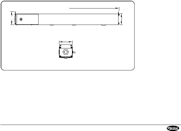
Dimensions |
|
|
|
|
|
|
|
|
Width |
Depth |
Height |
Height |
|
|
|
Model |
|
(A) |
(B) |
(C) |
(D) |
|
|
HL-18 |
|
18″ |
3″ |
3″ |
2-1/2″ |
|
|
|
(457 mm) |
(76 mm) |
(76 mm) |
(64 mm) |
|
|
|
HL-24 |
|
24″ |
3″ |
3″ |
2-1/2″ |
|
|
HL-24-2 |
(610 mm) |
(76 mm) |
(76 mm) |
(64 mm) |
|
|
|
HL-30 |
|
30″ |
3″ |
3″ |
2-1/2″ |
|
|
HL-30-2 |
(762 mm) |
(76 mm) |
(76 mm) |
(64 mm) |
|
|
|
HL-36 |
|
36″ |
3″ |
3″ |
2-1/2″ |
|
|
HL-36-2 |
(914 mm) |
(76 mm) |
(76 mm) |
(64 mm) |
|
|
|
HL-42 |
|
42″ |
3″ |
3″ |
2-1/2″ |
|
|
HL-42-2 |
(1067 mm) |
(76 mm) |
(76 mm) |
(64 mm) |
|
|
|
HL-48 |
|
48″ |
3″ |
3″ |
2-1/2″ |
|
|
HL-48-2 |
(1219 mm) |
(76 mm) |
(76 mm) |
(64 mm) |
|
|
|
HL-54 |
|
54″ |
3″ |
3″ |
2-1/2″ |
|
|
HL-54-2 |
(1372 mm) |
(76 mm) |
(76 mm) |
(64 mm) |
|
|
|
HL-60 |
|
60″ |
3″ |
3″ |
2-1/2″ |
|
|
HL-60-2 |
(1524 mm) |
(76 mm) |
(76 mm) |
(64 mm) |
|
|
|
HL-66 |
|
66″ |
3″ |
3″ |
2-1/2″ |
|
|
HL-66-2 |
(1676 mm) |
(76 mm) |
(76 mm) |
(64 mm) |
|
|
|
HL-72 |
|
72″ |
3″ |
3″ |
2-1/2″ |
|
|
HL-72-2 |
(1829 mm) |
(76 mm) |
(76 mm) |
(64 mm) |
|
|
|
|
|
|
|
|
|
|
 A
A
C |
D |
|
Front View
B
Side View
Dimensions
Form No. HLm-0214 |
5 |
|
INSTALLATION |
English |
|
General |
Adjustable Angle Bracket Mounting |
|
Use the information in this section to prepare for installation of |
mounting a display light with adjustable angle brackets |
|
a Glo-Rite® Display Light. |
permanently attaches the unit to the underside of a shelf. Units |
|
|
can be mounted to a flat shelf or a shelf with rolled/flanged |
|
WARNING |
edges. |
|
Use the following procedure to install adjustable angle brackets |
||
ELECTRIC SHOCK HAZARD: |
||
on each end of the unit. |
||
• Unit must be installed by a qualified electrician. |
||
|
||
Installation must conform to all local electrical codes. |
1. Position the unit on a flat surface on its side with the Power |
|
Installation by unqualified personnel will void unit |
I/O (on/off) switch facing up. |
|
warranty and may lead to electric shock or burn, as well |
2. Remove the two top screws on the end of the unit. |
|
as damage to unit and/or its surroundings. |
||
3. align the adjustable angle bracket with the mounting holes. |
||
• Consult a licensed electrical contractor for proper |
||
electrical installation conforming to local electrical |
4. Secure the angle bracket with the previously removed |
|
codes and the National Electrical Code (N.E.C.). |
screws. |
|
FIRE HAZARD: Locate unit the correct distance from |
5. Fasten the angle brackets to the underside of the shelf |
|
combustible walls and materials. If safe distances are not |
using appropriate fasteners (not supplied by Hatco). |
|
maintained, discoloration or combustion could occur. |
|
|
1. Remove the unit from the carton. |
Adjustable Angle |
|
NOTE: To prevent delay in obtaining warranty coverage, |
Bracket |
|
|
||
complete online warranty registration. See the |
|
|
ImPORTaNT OWNER INFORmaTION section for |
|
|
details. |
|
|
2. Remove tape and protective packaging from all surfaces of |
|
|
the unit. |
|
|
3. Install/mount the unit in an appropriate location. |
adjustable angle Bracket Installation |
|
a. For suspension installation, refer to “Suspension |
||
|
||
mounting” in this section. |
Electrical Information |
|
b. For permanent unit installation, refer to “adjustable |
||
angle Bracket mounting” in this section. |
Hatco provides a 1/2" (12 mm) trade size knockout opposite the |
|
Suspension Mounting |
Power I/O (on/off) switch, 6" (152 mm) long pigtail wire leads, |
|
Suspension mounting attaches a display light to an overhead |
and a separate grounding terminal in the wiring compartment. |
|
For correct installation, provide supply wires rated for at least 194° |
||
surface determined by a qualified installer. |
||
|
F (90° C) from a properly sized fused disconnect or circuit breaker |
|
WARNING |
conforming to local electrical codes. Use UL recognized wire nuts |
|
rated for at least 194° F (90° C) and properly sized for connection. |
||
For installation with chains, make sure the chains have |
Consult a local licensed electrical contractor if you have any |
|
sufficient strength and are securely fastened to both the |
||
questions on proper installation. Refer to the Electrical Rating |
||
unit and the mounting location. Poorly installed chains |
||
Chart for specific information. |
||
may cause the unit to loosen and fall. Do not place |
||
|
||
anything on top of units installed with chains. |
|
|
1. Prepare the overhead mounting system for suspension |
|
|
mounting. make sure the system is secure and is set up so |
|
|
the unit will be suspended at a level, safe, and proper |
|
|
distance from walls, counter, and food. |
|
|
2. Suspend the unit using the two suspension holes on both |
|
|
of the suspension brackets. |
|
|
3. Carefully lift the unit and attach each end of the unit to the |
|
|
overhead mounting system. make sure the unit is level. |
|
|
Suspension |
|
|
Bracket |
|
Suspension mounting |
|
|
|
6 |
Form No. HLm-0214 |
|
 Loading...