

Page 1
Models:
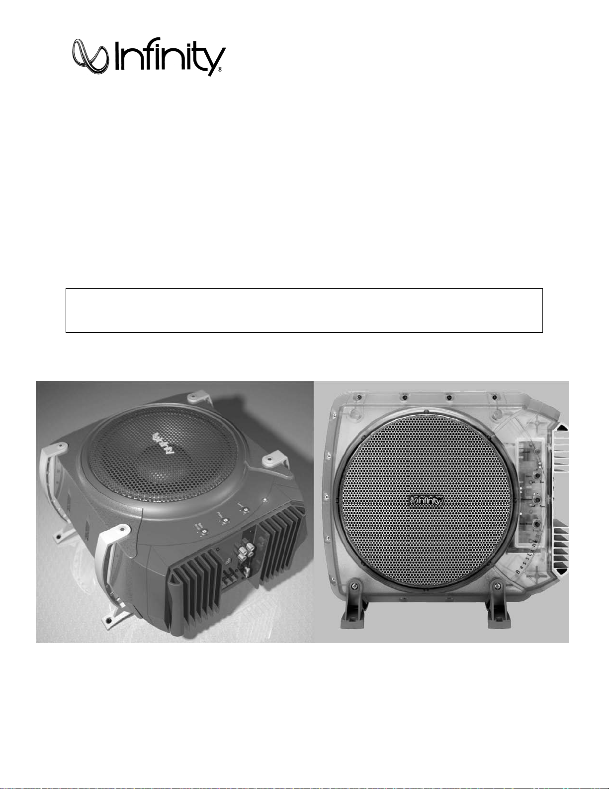
BassLink
BassLink
(Remote Level Cont rol Ready)
BassLink X
Powered Automotive Subwoofer
SERVICE MANUAL
Infinity Systems, Inc.
250 Crossways Park Dr.
Woodbury, New York 11797
Rev 2 7/2003
Page 2

Contents
1
ALL MODELS BASSLINK
SPECIFICATIONS …………………………………………..……………2
CONNECTIONS/APPLICATIONS ………………………………………3
TUNING BASSLINK…………………………………………………….…6
TROUBLESHOOTING ……………………………………………………7
TEST SETUP PROCEDURE ……………..………..……………………8
BASSLINK (Original version without Remote Level Control jack)
SERVICE BULLETIN INF2000-03 ………………………………………10
EXPLODED VIEW …………………………………………….…..………11
MECHANICAL PARTS LIST ……………….………………………….…12
BLOCK DIAGRAM …………..……………..………….………………….13
PCB DRAWINGS …………………………….……………………………14
ELECTRICAL PARTS LIST ………………………………………………24
SCHEMATICS …………………………………………………………..…29
PACKAGING …………………………………………………………….…31
BASSLINK or BASSLINK X (Versions with Remote Level Control jack)
SERVICE BULLETIN INF2003-01 ………………………………………33
EXPLODED VIEW ………………………….…………………..…………34
MECHANICAL PARTS LIST …………….….……………………………35
BLOCK DIAGRAM ………………………..………….…………………...36
PCB DRAWINGS …………………………….……………………………37
ELECTRICAL PARTS LIST ………………………………………………44
SCHEMATICS …………………………………………………………..…50
PACKAGING …………………………………………………………….…54
ALL MODELS BASSLINK
INTEGRATED CIRCUIT DIAGRAMS ………………………..…………55
Page 3

Basslink/Basslink X
2
BASSLINK/BASSLINK w/ Remote Level Control/BASSLINK X
Amplifier Power: 200W RMS @10% THD
Frequency Response: 20Hz – 120Hz
THD @ 30W 1.0%
Input Sensitivity: 50mV – 4V Line-Level Input
Maximum Input Sensitivity 7mV Line-Level Input
(Gain level @ Max) 120mV Universal Interface
Crossover Frequency: 50Hz – 120Hz
Crossover Slope: 12dB/octave
Bass Boost: –6 to +3 dB @ 40Hz
Signal-Noise Ratio 65dB (Wide band w/ 22K LPF)
Max Gain Level Noise 3.0 mV Basslink
(Level pot Max.) 1.8 mV Basslink w/ Remote Level Control
Max Gain Level Noise 2.0 mV Basslink
(Level pot Min.) 1.7 mV Basslink w/ Remote Level Control
Auto On/Off Time From 1 1/2 to 5 min.
Gain boost (min to max) 9.0 dB
Fuse: 25A Basslink
Specifications
120W RMS @1% THD
1V – 16V Universal Interface
1.8 mV Basslink X
1.7 mV Basslink X
(depending on last input signal level)
20A Basslink w/ Remote Level Control
20A Basslink X
Maximum Current Draw: 12A
Quiescent Current Draw: <800 mA
Protection Circuits:
Over/Under voltage 17.5, 8.5 VDC
Temperature 95° C
Short Circuit w/ 0.1 W resistor
DC Offset Yes
Dimensions: 14-1/2" x 12-1/2" x 8-1/2" (L x W x H)
(369mm x 318mm x 216mm)
Weight 16 lbs./7.2kg
Infinity continually strives to update and improve existing products, as well as create new ones. The specifications and
construction details in this and related Infinity publications are therefore subject to change without notice.
Page 4
3
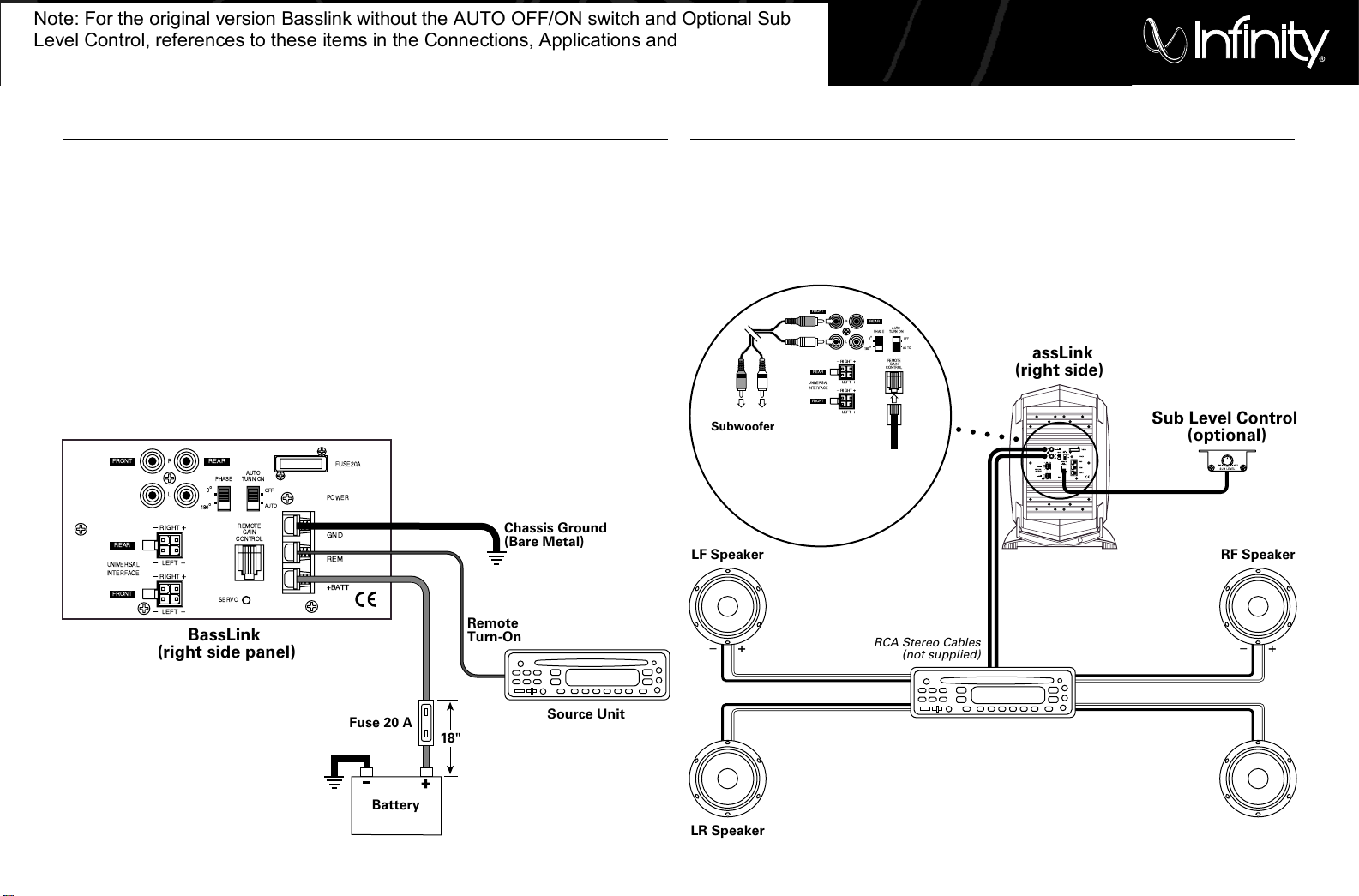
Connect power to BassLink, as shown in Figure 5.
Also observe these installation tips:
• Use at least #12 AWG wire for the +BATT
(+12 Vdc) and GND (ground) connections. If
needed, use at least a #20 AWG wire for the
REM (remote) connection.
• Route all power wires through a grommet in
the vehicle’s firewall. If a factory grommet is
unavailable, install one.
• Connect a short GND wire from BassLink to the
nearest bare metal surface. For a good connection, scrape away paint from the metal surface
and use a screw with a lock (star) washer.
Figure 5. Power connections for BassLink.
• Install a fuse holder with a 20 A fuse within 18"
of the battery + terminal (see Figure 5).
• The REM connection requires +5 to +12 Vdc
signal for BassLink to turn on remotely. Most
head units with preamp outputs provide this
remote voltage signal. For speaker-level applications, a remote connection is not required,
since BassLink’s Auto Turn-On feature will
sense voltage on the speaker wires to
automatically turn on BassLink.
IMPORTANT:To enable BassLink’s Auto
Turn-On feature, set AUTO TURN-ON to the
AUTO position (see Figure 12 on page 6).
POWER CONNECTIONS
BassLink is equipped with four line-level (RCA)
inputs and four speaker-level inputs. Any combination of line-level and speaker-level inputs may be
used to provide nonfading bass when connected to
a head unit with four outputs.
Figure 6. BassLink audio connections for a head
unit with two line-level or subwoofer (RCA) outputs.
To help you plan your installation, we included
five system applications in Figures 6 through 10
on pages 3 through 5. For more system ideas, see
your authorized Infinity car-audio dealer.
Note: The applications show the optional remote
SUB LEVEL control which installs under the dashboard for easy in-car bass level adjustments.
APPLICATIONS
R
L
+BATT
REM
GND
POWER
FUSE20A
PHASE
REMOTE
GAIN
CONTROL
SERVO
UNIVERSAL
INTERFACE
REAR
FRONT
FRONT REAR
Ð RIGHT +
Ð
LEFT +
Ð
RIGHT +
Ð
LEFT +
0
¡
180
¡
OFF
AUTO
AUTO
TURN ON
Chassis Ground
(Bare Metal)
BassLink
(right side panel)
Remote
Turn-On
Fuse 20 A
Source Unit
18"
Battery
R
L
+BATT
REM
GND
POWER
FUSE20A
PHASE
REMOTE
GAIN
CONTROL
SERVO
UNIVERSAL
INTERFACE
REAR
FRONT
FRONT REAR
ÐRIGHT+
Ð
LEFT+
Ð
RIGHT+
Ð
LEFT+
0
¡
180
¡
OFF
AUTO
AUTO
TURNON
R
L
PHASE
REMOTE
GAIN
CONTROL
UNIVERSAL
INTERFACE
REAR
FRONT
FRONT
REAR
ÐRIGHT +
Ð
LEFT +
Ð
RIGHT+
Ð
LEFT +
0
¡
180
¡
OFF
AUTO
AUTO
TURNON
LF Speaker
+–
RF Speaker
LR Speaker
Subwoofer or
Line-Level
Outputs
(on Source Unit)
Sub Level
Control
(optional)
RL
RR Speaker
+–
+–+–
Source Unit
BassLink
(right side)
Sub Level Control
(optional)
+–
RCA Stereo Cables
(not supplied)
Note: For the original version Basslink without the AUTO OFF/ON switch and Optional Sub
Level Control, references to these items in the Connections, Applications and Controls sections
can be ignored - all other information is valid.
Page 5
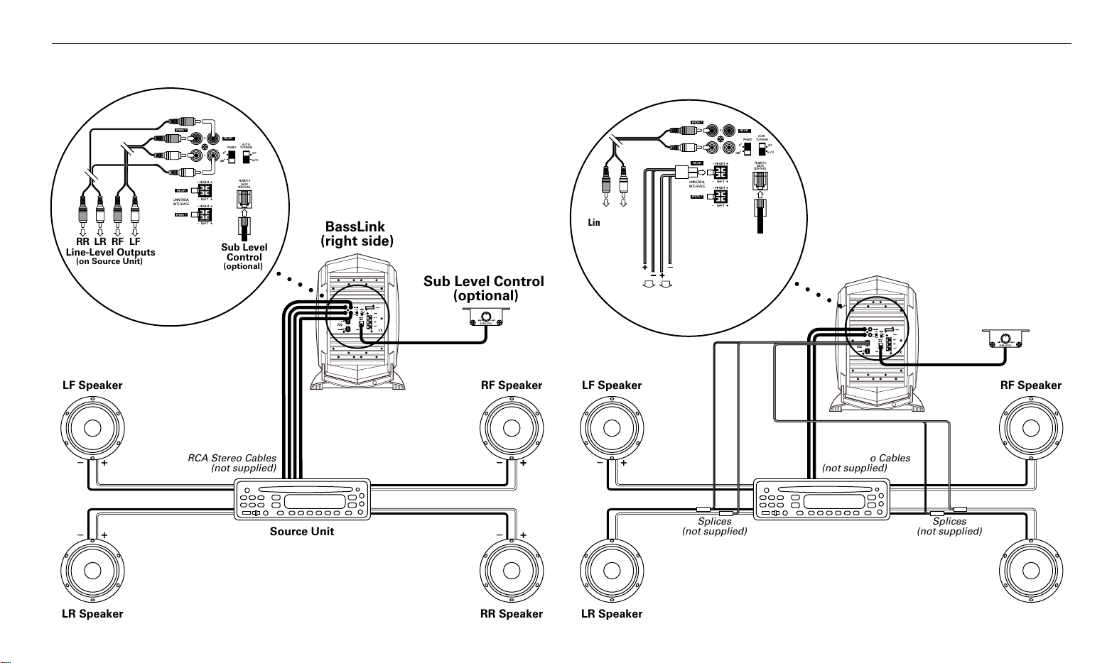
APPLICATIONS (CONTINUED)
R
L
+BATT
REM
GND
POWER
FUSE20A
PHASE
REMOTE
GAIN
CONTROL
SERVO
UNIVERSAL
INTERFACE
REAR
FRONT
FRONT REAR
ÐRIGHT+
Ð
LEFT+
Ð
RIGHT+
Ð
LEFT+
0
¡
180
¡
OFF
AUTO
AUTO
TURNON
R
L
PHASE
REMOTE
GAIN
CONTROL
UNIVERSAL
INTERFACE
REAR
FRONT
FRONT
REAR
ÐRIGHT +
Ð
LEFT +
Ð
RIGHT+
Ð
LEFT +
0
¡
180
¡
OFF
AUTO
AUTO
TURNON
LF Speaker
+–
RF Speaker
LR Speaker
Line-Level Outputs
(on Source Unit)
Sub Level
Control
(optional)
RFLRRR LF
RR Speaker
+–
+–+–
Source Unit
BassLink
(right side)
Sub Level Control
(optional)
+–
RCA Stereo Cables
(not supplied)
R
L
+BATT
REM
GND
POWER
FUSE20A
PHASE
REMOTE
GAIN
CONTROL
SERVO
UNIVERSAL
INTERFACE
REAR
FRONT
FRONT REAR
ÐRIGHT+
Ð
LEFT+
Ð
RIGHT+
Ð
LEFT+
0
¡
180
¡
OFF
AUTO
AUTO
TURNON
R
L
PHASE
REMOTE
GAIN
CONTROL
UNIVERSAL
INTERFACE
REAR
FRONT
FRONT
REAR
ÐRIGHT +
Ð
LEFT +
Ð
RIGHT+
Ð
LEFT +
0
¡
180
¡
OFF
AUTO
AUTO
TURNON
LF Speaker
+–
RF Speaker
LR Speaker
Line-Level
Outputs
(on Source Unit)
Sub Level
Control
(optional)
RF LF
Speaker Wires
(spliced)
RR LR
RR Speaker
+–
+–+–
Source Unit
BassLink
(right side)
Sub Level Control
(optional)
VIOLET GREEN/BLACK
VIOLET/BLACK GREEN
+–
RCA Stereo Cables
(not supplied)
Splices
(not supplied)
Splices
(not supplied)
Figure 7. BassLink audio connections for a head
unit equipped with four line-level (RCA) outputs.
Figure 8. BassLink audio connections for a head
unit equipped with two line-level (RCA) outputs
and two speaker-level outputs.
4
Page 6
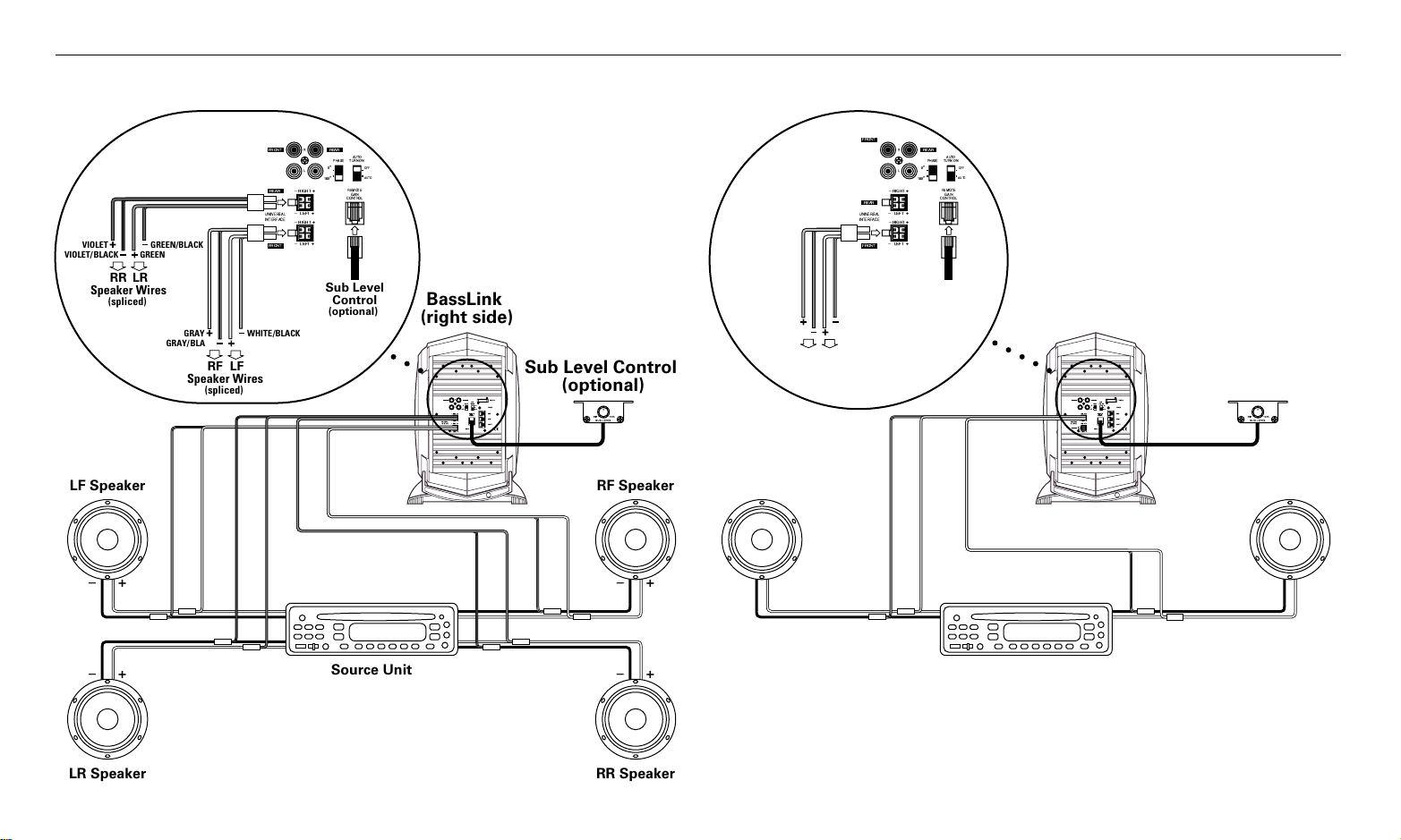
APPLICATIONS (CONTINUED)
R
L
+BATT
REM
GND
POWER
FUSE20A
PHASE
REMOTE
GAIN
CONTROL
SERVO
UNIVERSAL
INTERFACE
REAR
FRONT
FRONT REAR
ÐRIGHT+
Ð
LEFT+
Ð
RIGHT+
Ð
LEFT+
0
¡
180
¡
OFF
AUTO
AUTO
TURNON
R
L
PHASE
REMOTE
GAIN
CONTROL
UNIVERSAL
INTERFACE
REAR
FRONT
FRONT REAR
ÐRIGHT +
Ð
LEFT +
Ð
RIGHT+
Ð
LEFT +
0
¡
180
¡
OFF
AUTO
AUTO
TURNON
LF Speaker
+–
RF Speaker
LR Speaker
Sub Level
Control
(optional)
Speaker Wires
(spliced)
RR LR
RR Speaker
+–
+–+–
Source Unit
BassLink
(right side)
Sub Level Control
(optional)
VIOLET GREEN/BLACK
VIOLET/BLACK GREEN
Speaker Wires
(spliced)
RF LF
GRAY WHITE/BLACK
GRAY/BLACK WHITE
+–
Splices
(not supplied)
Splices
(not supplied)
R
L
+BATT
REM
GND
POWER
FUSE20A
PHASE
REMOTE
GAIN
CONTROL
SERVO
UNIVERSAL
INTERFACE
REAR
FRONT
FRONT REAR
ÐRIGHT+
Ð
LEFT+
Ð
RIGHT+
Ð
LEFT+
0
¡
180
¡
OFF
AUTO
AUTO
TURNON
R
L
PHASE
REMOTE
GAIN
CONTROL
UNIVERSAL
INTERFACE
FRONT
FRONT
REAR
ÐRIGHT +
Ð
LEFT +
Ð
RIGHT+
Ð
LEFT +
0
¡
180
¡
OFF
AUTO
AUTO
TURNON
REAR
L Speaker
+–
R Speaker
Sub Level
Control
(optional)
Speaker Wires
(spliced)
R L
+–
Source Unit
BassLink
(right side)
Sub Level Control
(optional)
GRAY WHITE/BLACK
GRAY/BLACK WHITE
+–
Splices
(not supplied)
Splices
(not supplied)
Figure 9. BassLink audio connections for a head
unit equipped with four speaker-level outputs.
Figure 10. BassLink audio connections for a head
unit equipped with two speaker-level outputs.
5
Page 7
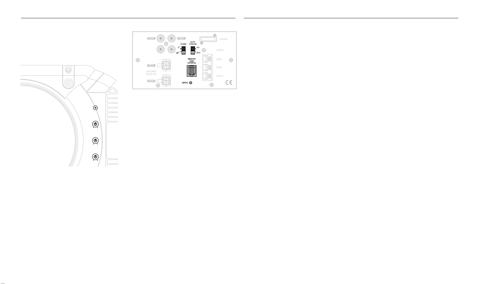
CONTROLS AND FUNCTIONS
Power
Gain
Min Max
50 Hz
Crossover
120 Hz
Bass Boost
-6 (dB) +3
(Blue on Basslink X)
TUNING BASSLINK
BassLink provides several controls and indicators
that simplify sonic integration with virtually any
vehicle’s unique acoustic properties. They are
located on the front and side panels, as shown in
Figures 11 and 12.
Figure 11. BassLink controls on the front panel.
POWER LED:This indicator will glow red when
BassLink is operational.
GAIN Control: Use this control to adjust the relative volume (loudness) of BassLink with respect
to the other speakers in the vehicle.
CROSSOVER: Use this control to adjust the
amount of high-frequency information present in
BassLink’s output. A lower value signifies less
high frequencies will be amplified.
BASS BOOST: Use this control to correct any
perceived peak or dip in the bass response
(typically around 40Hz in most vehicles). Set the
control to any value between –6dB and + 3dB,
according to what sounds best.
Figure 12. BassLink controls on right side panel.
R
FRONT REAR
L
Ð RIGHT +
REAR
Ð
LEFT +
UNIVERSAL
INTERFACE
RIGHT +
Ð
FRONT
Ð
LEFT +
AUTO
PHASE
TURN ON
0
¡
OFF
180
AUTO
¡
REMOTE
GAIN
CONTROL
SERVO
FUSE20A
POWER
GND
REM
+BATT
PHASE Control: Use this switch to reverse the
phase of BassLink’s output with respect to its
input. Choose the position (0° or 180°) that
sounds the best.
Note: Depending on BassLink’s orientation and
location in a vehicle, reversing the phase may
may (or may not) increase or decrease the
amount of upper bass being reproduced.
AUTO TURN-ON: For speaker-level connections,
use this switch to activate (or deactivate) BassLink’s
automatic turn-on circuit. For most speaker-level
applications, slide the switch to AUTO. However, if
your system produces false turn-on signals or uses
a remote (REM) connection, slide the switch to OFF.
REMOTE GAIN CONTROL: Use this RJ-11 jack to
connect the optional remote SUB LEVEL control.
SERVO LED:This indicator glows green when the
subwoofer is at maximum excursion and the
amplifier is modifying the output to maintain
maximum performance. Be sure to monitor this
indicator during BassLink setup (see Tuning
BassLink). When properly tuned, the SERVO LED
should light momentarily during high-level bass
transients. Avoid adjustments that cause the LED
to remain lit for extended periods.
1. Make sure the head unit is off and its volume
control is set to minimum.
2. On BassLink’s front panel, initially set all controls to their midpoint positions, as shown in
Figure 11. On BassLink’s side panel, initially set
PHASE to 0° and AUTO TURN-ON to AUTO, as
shown in FIgure 12.
3. Turn on the head unit and play a favorite music
track that has substantial bass. Set the volume
control to 75 percent of the total output
(approximately 3 o’clock on rotary controls).
4. Adjust the GAIN control clockwise until the
SERVO LED (on BassLink’s side panel) begins
to flash with each bass note but doesn’t stay
lit continuously.
5. Listen to your system, making a mental note
of the amount of upper bass being reproduced.
6. Switch the PHASE control to 180° and listen
again for upper bass content. There may be
more upper bass, less upper bass, or no
change at all. The position that provides the
most upper bass is correct, but choose either
setting according to your taste.
7. Adjust the CROSSOVER control clockwise or
counterclockwise until you hear only low-frequency information. For example, you should
NOT hear any vocals coming from BassLink
when seated in the normal listening position.
8. Adjust the BASS-BOOST control clockwise or
counterclockwise to suit your taste.
9. Recheck the SERVO LED to make sure it’s
flashing in time with the bass but is not lit
continuously. If it is lit continuously, adjust the
GAIN control counterclockwise until the
SERVO LED only flashes.
Note: In most cases, the above steps will provide
satisfactory tuning. However, the actual process
may require several readjustments of each control,
since the settings will interact with each other.
If necessary, consult your authorized Infinity
car audio dealer for help in tuning your system.
6
Page 8

Basslink/Basslink X
7
TROUBLESHOOTING
• PROBLEM:
POWER LED not lit.
CAUSES and SOLUTIONS:
1. Fuse is blown and needs replacement.
2. Head unit not functioning properly. Check
remote voltage, and power, ground or
remote connections.
• PROBLEM:
POWER LED is lit but there is no bass.
CAUSES and SOLUTIONS:
1. Inputs are not connected. Check connections.
2. Head-unit fader control is not set properly.
Adjust head-unit fader control to feed audio
signals to BassLink.
• PROBLEM:
BassLink sounds muddy or distorted.
CAUSES and SOLUTIONS:
1. Gain is set too high and SERVO LED is lit
constantly. Readjust GAIN control (see
Tuning BassLink on the previous page).
2. Bass is set too high. Readjust BASS BOOST
control (see Tuning BassLink on the previous
page).
3. Head-unit output is distorted or blown. See
your authorized Infinity car audio dealer.
APPLICABLE TO BASSLINK WITH LEVEL
CONTROL JACK AND BASSLINK X ONLY:
• PROBLEM:
BassLink turns on before head unit is completely on
and produces a “thump” sound.
CAUSE and SOLUTION:
For speaker-level connections, head unit is
producing a false turn-on signal. On BassLink’s
side panel, slide AUTO TURN-ON to OFF.
• PROBLEM:
BassLink’s POWER LED remains on after head
unit is turned off.
CAUSE and SOLUTION:
For speaker-level connections, this is normal
operation when AUTO TURN-ON is set to ON.
BassLink will remain on another 5 to 10 minutes
after sensing that audio signals are not present
before shutting down. If you prefer immediate shutdown, set AUTO TURN-OFF to OFF.
• PROBLEM:
No output from BassLink when head-unit
fader control set to front or rear (in a 4-channel
connection).
CAUSE and SOLUTION:
Input connections are improperly wired. Verify all
connections (see Applications section)
Page 9
BassLink/BassLink X
8
Equipment needed:
• Function/signal generator/sweep generator
• Integrated/Power Amplifier (capable of driving 2 ohm loads)
• 14 volt DC power supply 20A or greater with current-limit protection
• Multimeter
• RCA cable, Universal Interface molex connector, Speaker cables
General Unit Function (UUT = Unit Under Test)
Switch/Controls:
GAIN control full counterclockwise (Min)
CROSSOVER full clockwise (120 Hz)
BASS BOOST at center (12 o’clock)
PHASE, AUTO-ON - either position
1) From the signal generator, connect one line level (RCA) cable to the Basslink Line Level Input jacks (Front,L/R) on the UUT. Use
a Y-cable from a mono source if necessary to connect to both inputs.
2) Turn on generator, adjust to 100mV, 40 Hz.
3) Attach 14v DC source to Power terminals on UUT, including +14v to Remote connection. Red LED should ON. Turn LEVEL control full clockwise (Max)
4) Bass response should be heard and felt. Green servo light should not be illuminated.
5) Adjust the generator to 175mV, 40 Hz. Green servo light should turn ON. DO NOT DRIVE THE BASSLINK FOR MORE THAN A
FEW SECONDS AT THIS LEVEL OR THE UUT MAY GO INTO THERMAL PROTECTION
6) Turn off generator, turn GAIN control fully counterclockwise, disconnect RCA cable.
7) Optional: Attach the Universal Interface molex connector (Infinity part# 162A600D001) to the Basslink Universal Interface Jack
(Front,L/R) on the UUT. Both front/rear negative wires should be twisted and connected together; positive wires should be treated
likewise. Cables should be connected to an integrated amplifier fed by the signal generator.
8) Turn on generator and adjust so that speaker level input at the amplifier is 275mV, 40 Hz. Turn GAIN control full clockwise.
9) Bass response should be heard and felt. Green servo light should not be illuminated.
10) Adjust the generator to 500mV, 40 Hz. Green servo light should be ON. DO NOT DRIVE THE BASSLINK FOR MORE THAN A
FEW SECONDS AT THIS LEVEL OR THE UUT MAY GO INTO THERMAL PROTECTION
Sweep Function
1) Follow steps 1-3 above, using a sweep generator as a signal source – adjust the generator to 50mV, 40 Hz.
2) Sweep generator from 20Hz to 300Hz. Listen for any rattles, clicks, buzzes or any other noises. If any unusual noises are heard,
test woofer according to the instructions below.
Driver Function
1) Remove amplifier from the enclosure; (instructions in bulletin INF2000-03 page 8); detach connector M101 two-wire molex on the
main amplifier PCB.
2) Check DC resistance of woofer; it should be 2.3 ohms ±10%
3) Connect a pair of speaker cables to woofer terminals. Cables should be connected to an integrated amplifier fed by a signal generator. Turn on generator and adjust so that speaker level output is 6.0V.
4) Sweep generator from 20Hz to 1kHz. Listen to driver for any rubbing, buzzing, or other unusual noises.
SIGNAL
GENERATOR
AMPLIFIER
AC VOLT
METER (10V)
BASSLINK
UNDER TEST
00432
-
+
14V DC
Test Set Up Procedure
Page 10

Basslink
9
(Original version without remote
level control jack)
Page 11
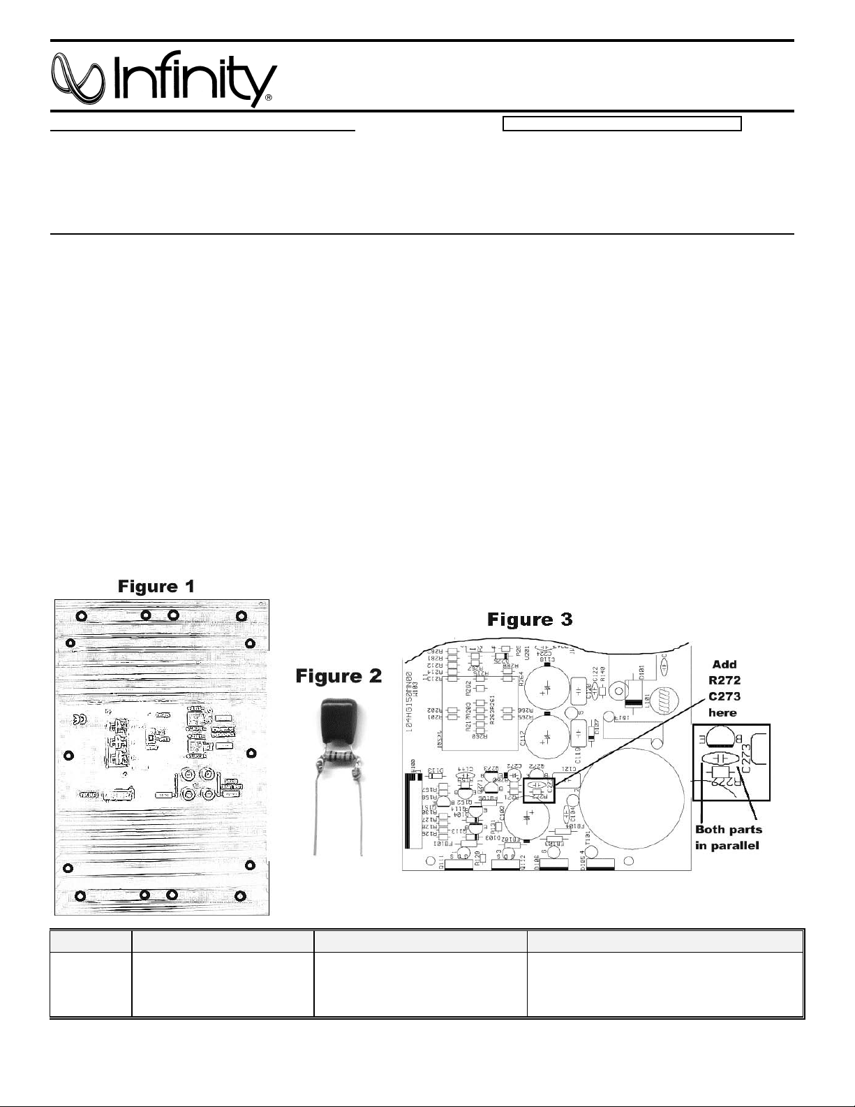
Service Bulletin
10
Service Bulletin INF2000-03 - October 2000 Warranty labor rate: MINOR repair
To: All Infinity Service Centers
Model: Basslink (version w/o AUTO-ON switch or REMOTE GAIN)
Subject: Unit will not turn off
In the event you receive a Basslink subwoofer with the complaint: “The unit will not turn off, even when
the audio signal is removed, and the Remote power connection is switched off” (indicated by the
Basslink’s red LED remaining ON), perform the following modification:
1) Set the unit on a padded surface and remove all external cables.
2) On the amplifier faceplate, remove only the (14) Phillips mounting screws as shown in Figure 1.
3) Remove the amplifier assembly from the enclosure. If the amp is turned around and supported correctly,
no other connectors need to be unplugged.
4) Add these two components:
1.0 Meg ohm 1/8W resistor, Infinity part# 299-1M
.01uf, 100v mylar capacitor, Infinity part# 140-PF2A103F
Solder these parts in parallel (See Figure 2); and attach to original location shown (See Figure 3), which is in
a narrow cavity between main power supply caps and transformer T101. There are two empty pads on the
PCB for these parts with marked designators R272 and C273.
5) New gaskets must be added to the amplifier mating surface; two pairs are required, four gaskets total:
Infinity part# 723D150 and #723C150
6) Replace the amplifier assembly and tighten all mounting screws. Use caution; a hand tool is
recommended to prevent stripping the threads in the enclosure.
7) Connect +12v to the unit and a signal cable, after the unit cycles ON, (red LED should be lit), remove the
signal and remote connection only (or shut off the music source if using the Universal Interface). Unit
should turn OFF after 3 - 10 minutes (as indicated by the red LED turning OFF).
Models Serial number Status Action
Add:
Basslink
All serial numbers affected
(version w/o AUTO-ON
switch or REMOTE GAIN)
The unit will not turn off when the
signal is removed, and Remote
connection is switched off
R272 1 Meg ohm 1/8W Resistor
C273 .01uf 100v Mylar Capacitor
New amplifier gaskets #723D150, 723C150
Infinity Systems Inc. 250 Crossways Park Dr. Woodbury, New York 11797 (516) 496-3400
Page 12
BassLink
11
Exploded View
J
M
1
2
L
K
3
4
5
12
8
11
13
9
8
29
28
6
7
8
12
J
H
G
F
E
D
28
7
13
9
35
29
G
H
I
F
E
K
31
6
16
25
24
42
32
27
K
26
17
25
11
43
15
H
22
23
19
20
18
J
I
6
19
15
44
2
30
9
10
21
9
14
C
B
A
1
2
3
4
5
6
7
8
12
9
10
11
4
13
14
15
39
39
M
16
L
1
K
38
34
D
15
B
15
39
14
36
5
3
37
40
F
E
37
G
D
38
40
41
C
40
B
A
36
39
J
H
G
F
E
D
12
40
12
1
C
A
36
36
33
12
9
10
11
13
14
15
C
B
A
16
NOTE: THIS DRAWING AND MECHANI CA L PARTS
LIST ARE FOR REFERENCE PURPOSES ONLY;
THE MAIN ENCLOSURE OF THE BASSLINK
SUBWOOFER, WITH THE EXCEPTION OF THE
AMPLIFIER ASSEMBLY, IS
NON-SERVICABLE.
COMPLETE ENCLOSURE W/ DRIVERS
PART# BASSLINK/ASSEMBLY
00425
Page 13
BassLink
12
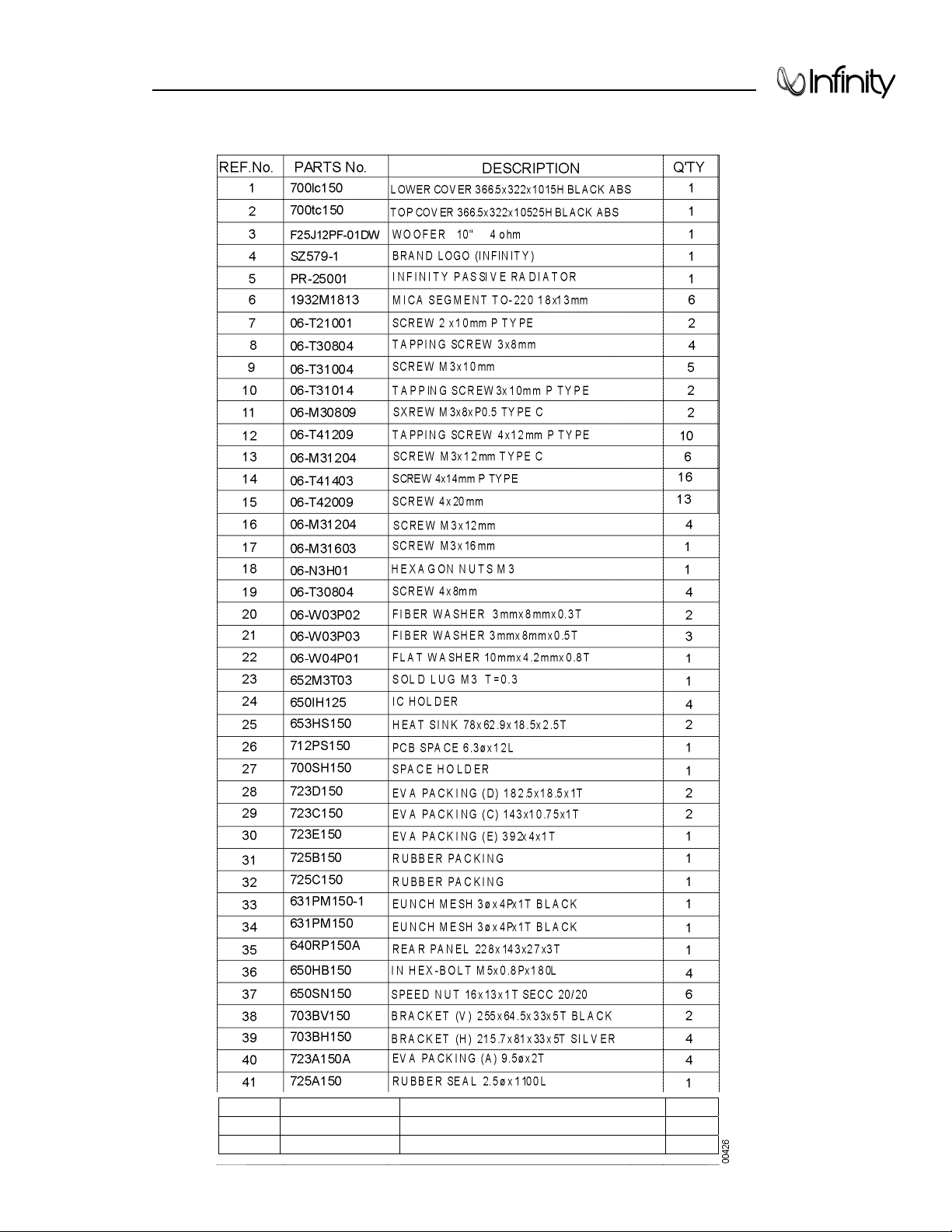
Mechanical Parts List
42 NLA-REPAIR MAIN ASS'Y PCB
43 1010DS150-1 AMP-SMD ASS'Y
44 NLA-REPAIR TONE CONTROL PCB ASS'Y
1
1
1
Page 14
BassLink
13
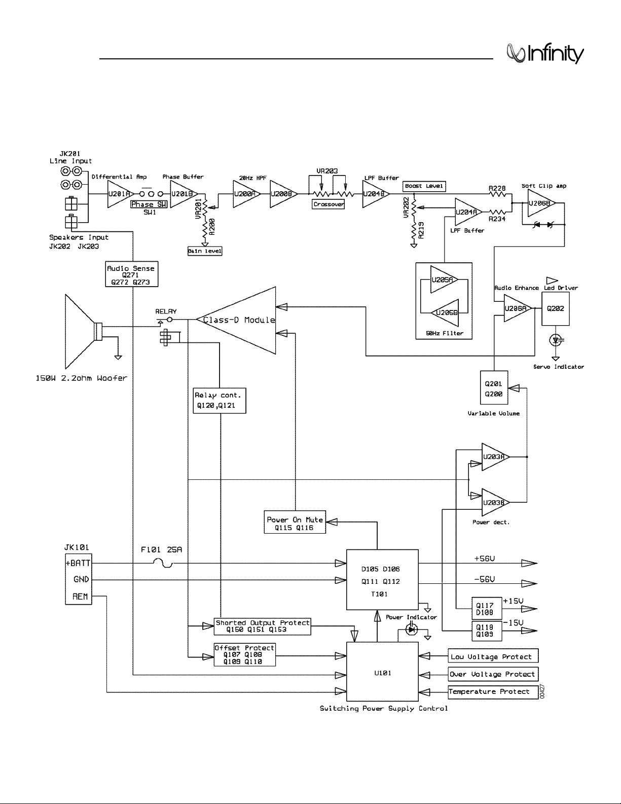
Block Diagram
Page 15
BassLink
14
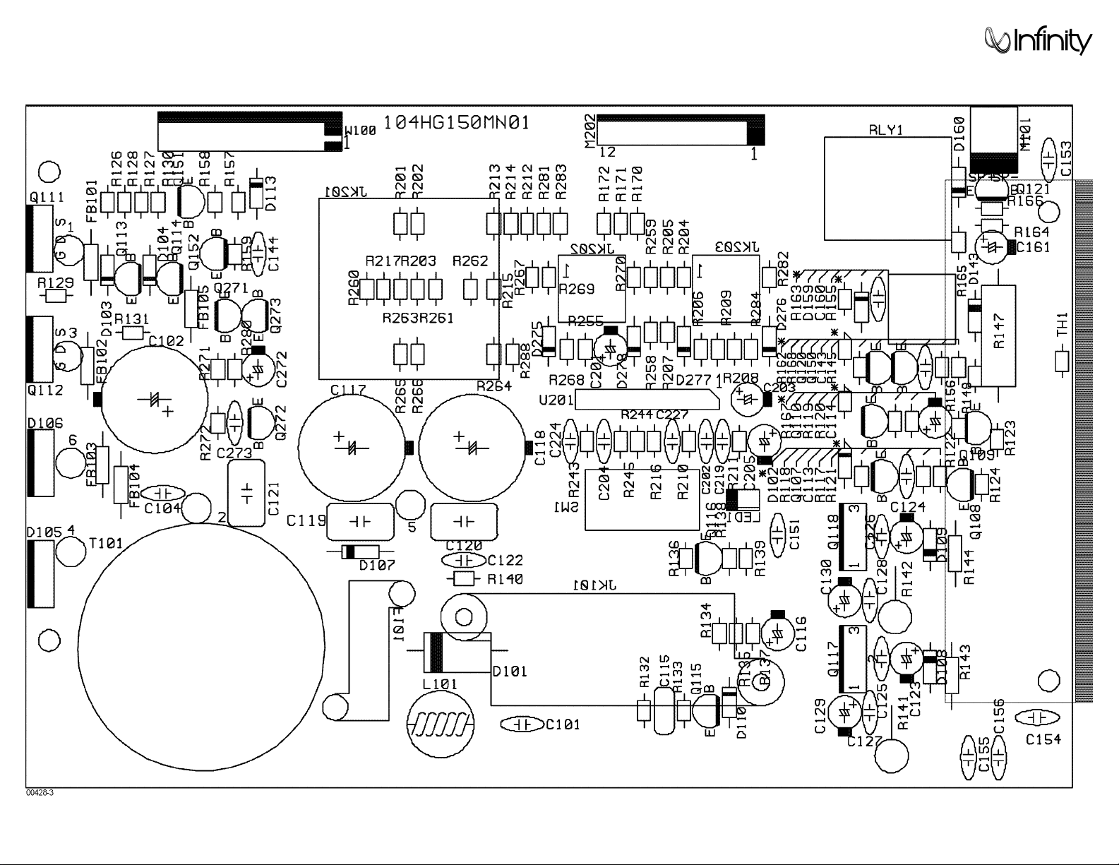
Main PCB
Page 16
BassLink
15
Main PCB (Cont.)
Page 17
BassLink
16
Main PCB (Cont.)
Page 18

BassLink
17
Main PCB (Cont.)
Page 19

BassLink
18
Main PCB (Cont.)
Page 20

BassLink
19
Main PCB (Cont.)
Page 21

BassLink
20
Tone Control/Switching Controller PCB
Page 22

BassLink
21
Tone Control/Switching Controller PCB (Cont.)
Page 23

Power Amp PCB
22
Page 24

Power Amp PCB (Cont'd)
23
Page 25

BassLink
24
Electrical Parts List
Main PCB
Resistors
11016472j26 R212,R217,R281,R282,R283,R284 8 RES,CB 4.7K 1/6W ±5%
R260,R288
11016103j26 R117,R118,R119,R122,R123,R124 22 RES,CB 10K 1/6W ±5%
R132,R133,R137,R138,R140,R166
R167,R168,R201,R204,R208,R213
R265,R266,R269,R270
11016470j26 R165 1 RES,CB 47Ω 1/6W ±5%
11016223j26 R121,R134,R164 3 RES,CB 22K 1/6W ±5%
11016393j26 R163,R157 2 RES,CB 39K 1/6W ±5
11016100j26 R162 1 RES,CB 10Ω 1/6W ±5%
11016562j26 R159 1 RES,CB 5.6K 1/6W ±5%
11016102j26 R136,R158 1 RES,CB 1K 1/6W ±5%
11016222j26 R216,R243,R244,R245 1 RES,CB 2.2K 1/6W ±5%
11016182j26 R145 1 RES,CB 1.8K 1/6W ±5%
11016221j26 R156 1 RES,CB 220Ω 1/6W ±5%
11016270j26 R126,R127 1 RES,CB 27Ω 1/6W ±5%
11016104j26 R120,R135,R255 1 RES,CB 100K 1/6W ±5%
11112332j10 R143,R144 1 RES,CB 3.3K 1/2W ±5%
11016473j26 R148 1 RES,CB 47K 1/6W ±5%
11016513j26 R202,R203,R214,R215,R261,R262 8 RES,CB 51K 1/6W ±5%
R263,R264
11016105j26 R280 1 RES,CB 1M 1/6W ±5%
11016106j26 R271 1 RES,CB 10M 1/6W ±5%
11016204j26 R205,R206,R207,R209,R258,R259 8 RES,CB 200K 1/6W ±5%
R267,R268
11016243j26 R210,R211 2 RES,CB 24K 1/6W ±5%
161506520 R171,R170,R172 3 RES,CB 0R JUMPER
11030621jk3 R141,R142 3 RES,MF 620Ω 3W ±5%
11016471j26 R130,R128 2 RES,CB 470Ω 1/6W ±5%
11016101j26 R129,R131 2 RES,CB 100Ω 1/6W ±5%
11202102JK1 R147 1 RES,CB 1k 2W ±5%
11350s68j00 R155 1 RES,CEW 0.068Ω 5W ±5%
1091ttc802j0 TH1 1 NTC,TTC-802(JS)
Capacitors
1302f104z500 C154 1 CAP, CA Disc 0.1U 50V
1302f104z503 C101,C104,C113,C122,C127,C128 12 CAP, CA Disc0.1U 50V
C144,C152,C153,C160,C224,C227
132273J503 C143 1 CAP, MY 0.027uF 50V 5%
132104kb04 C121 1 CAP, MY 0.1uF 200V 10%
132104JA03 C115,C119,C120 3 CAP, MY 0.1uF 100V ±5%
1353227m10 C161 1 CAP, E 220U 10V ±20%
1353335m50 C116 1 CAP, E3.3uF 50V ±20%
1354108c80 C117,C118 2 CAP, E 1000uF 80V
135433816 C102 1 CAP, E 3300uF 16V ±20%
1353226m50 C201,C203 2 CAP, E 22U 50V ±20%
1353227m16 C272 1 CAP, E 220U 16V ±20%
1353106m50 C205 1 CAP, E 10U 50V ±20%
1353107m16 C129,C130 2 CAP, E 100uF 16V ±20%
1353337m16 C114 1 CAP, E 330uF 16V ±20%
Part# Reference Designator Qty Description
Page 26

BassLink
25
Electrical Parts List (Cont.)
1353476m16 C123,C124 2 CAP, E 47U 16V ±20%
1302b221k503 C202,C204,C219 3 CAP, CA Disc 220p 50V ±10%
132103ja03 C155,C156 2 CAP, MY 0.01V 100V ±5%
Semiconductors
19006m45581 U201 1 I.C. NJRC NJM4558LD Dual Op-Amp
19510204gd LD1 1 LED, 3mm Green
192027c1815gr Q108,Q110,Q115,Q120,Q121,Q151 9 Trans NPN 60V .15A 2SC1815GR
Q271,Q272,Q273
192021d669a Q117 1 Trans NPN 180V 1.5A2SD669A
192027c2235y Q150 1 Trans NPN 120V 0.8A 2SC2235
192028a1015gr Q107,Q109,Q113,Q114,Q116,Q152 6 Trans PNP 50V .15A 2SC1015GR
192022b649a Q118 1 Trans PNP 180V 1.5A 2SB649A
19216355ne06 Q111,Q112 2 FET N-CH 60V 50A IRFZ44/STP55NE06
197131n4148 D102,D103,D104,D110,D113,D143 12 Diode 1N4148
D159,D160,D275,D276,D277,D278
19730sf16 D107 1 Diode SF16
197101n5402 D101 1 Diode 1N5402
197301604gd D105,D106 2 Diode SF1604GD
19915001503 D108,D109 2 Zener 15V 1/2W
Connectors
1751b08v01 M202 1 Wafer 8Pin PH2.0mm
1759d02v01 M101 1 Wafer 2Pin VH3.96mm
1745te112j JK101 1 Terminal TE1-12J
1759h04v01 JK202,JK203 2 Wafer 4Pin 4.2mm
174040124bg JK201 1 RCA JACK JK040124BG
Wires
162a040d001 W101 1 2Pin spk Wires conn Asy
162a600d001 W202(1-8Pin) 1 8Pin Flat Wire conn Asy
162a600d002 W202(9-12Pin) 1 4Pin Multi-Wires Asy
Miscellaneous
180p752209 SW1 1 SW SSP752209-25JJ1 PHASE
1201000003 FB104,FB101,FB102,FB103,FB105 5 Ferrite BEAD
154k025a800 F101 1 Fuse ATC 25A
12214050K4160 L101 1 Inductor 5uH/15A
171urwh112d RLY1 1 RELAY, RWH112D
150r29191501 T101 1 Transformer YT802-007A
1559f30240 F101 1 Fuse holder
Switching Controller PCB
Resistors
11016682j26 R113 1 RES, CB 6.8K 1/6W ±5%
11016102j26 R103,R115 2 RES, CB 1K 1/6W ±5%
11016221j26 R102 1 RES, CB 220Ω 1/6W ±5%
11016222j26 R112 1 RES, CB 2.2K 1/6W ±5%
11016681j26 R106,R107 2 RES, CB 680Ω 1/6W ±5%
11016472j26 R111,R116 2 RES, CB 4.7K 1/6W ±5%
11016103j26 R108,R110,R151 3 RES, CB10K 1/6W ±5%
11016432j26 R105 1 RES,CB4.3K 1/6W ±5%
Part# Reference Designator Qty Description
Page 27

BassLink
26
Electrical Parts List (Cont.)
11016104j26 R114,R150 2 RES, CB 100K 1/6W ±5%
11016100j26 R109 1 RES, CB 10Ω 1/6W ±5%
11016123j26 R104 1 RES, CB 12K 1/6W ±5%
11016562j26 R100 1 RES, CB 5.6K 1/6W ±5%
11016183j26 R152 1 RES, CB 18K 1/6W ±5%
11016471j26 R153 1 RES, CB 470Ω 1/6W ±5%
Capacitors
1302f104z503 C106,C107,C109,C111,C112,C133 6 CAP, CA Disc 0.1uF 50V +80/-20%
1303f272ka04 C110 1 CAP, CA Disc 2700P 100V ±10%
1353226m16 C108 1 CAP, E22U 16V ±10%
1353337m16 C134 1 CAP, E330uF 16V ±10%
Semiconductors
197131n4148 D114,D111 2 Diode 1N4148
19915000623 D112 1 Zener 6.2V 1/2W
192028a965y Q103 1 Trans PNP 120V 0.8A 2SA965Y
192028a1015gr Q105,Q119 2 Trans PNP 50V .15A 2SC1015GR
192027c1815gr Q104,Q106 2 Trans NPN 60V .15A 2SC1815GR
19301494cn U101 1 I.C.TI TL494CN PWM
Miscellaneous
1759f40hr2 M100 1 PIN Header 10Pins 2.54mm
Tone Control PCB
Resistors
11016123j26 R227,R234 2 RES, CB 12K 1/6W ±5%
11016103j26 R221,R229,R285,R294 4 RES, CB 10K 1/6W ±5%
11016474j26 R220,R278 2 RES, CB 470K 1/6W ±5%
11016102j26 R219,R222,R233 3 RES, CB 1K 1/6W ±5%
11016393j26 R223 1 RES, CB 39K 1/6W ±5%
11016222j26 R228 1 RES, CB 2.2K 1/6W ±5%
11016204j26 R237 1 RES, CB 200K 1/6W ±5%
11016243j26 R225 1 RES, CB 24K 1/6W ±5%
11016562j26 R238 1 RES, CB 5.6K 1/6W ±5%
11016392j26 R224 1 RES, CB 3.9K 1/6W ±5%
11016223j26 R240,R241,R242,R250,R254,R287 6 RES, CB 22K 1/6W ±5%
11016471j26 R239 1 RES, CB 470Ω 1/6W ±5%
11016153j26 R218,R252 2 RES, CB 15K 1/6W ±5%
11016683j26 R251 1 RES, CB 68K 1/6W ±5%
11016333j26 R253,R277 2 RES, CB 33K 1/6W ±5%
11016122j26 R295 1 RES, CB 1.2K 1/6W ±5%
11016511J26 R200,R256,R286 3 RES, CB 510Ω 1/6W ±5%
11016432j26 R279 1 RES, CB 4.3K 1/6W ±5%
11016755j26 R293 1 RES, CB 7.5M 1/6W ±5%
11016472j26 R275,R276 1 RES, CB 4.7K 1/6W ±5%
11016273j26 R274 1 RES, CB 27K 1/6W ±5%
11016473j26 R257,R273,R290 3 RES, CB 47K 1/6W ±5%
115v503b101 VR201 1 POT 50KΩ GAIN
115v503b101 VR202 1 POT 50KΩ BASS BOOST
115v503b201 VR203 1 POT 50KΩ X 2 LP FREQ.
Part# Reference Designator Qty Description
Page 28

BassLink
27
Electrical Parts List (Cont.)
Capacitors
129a224j633 C215 1 CAP F 0.22uF 63V ±5%
129a823j633 C216 1 CAP F 0.082U 63V ±5%
129a334j633 C260,C261,C262,C263 4 CAP F 0.33uF 63V ±5%
1302b101k503 C214C217,C242,C252,C253 5 CAP CA Disc 100P 50V ±10%
1302f104z503 C229,C231,C233,C234,C235 8 CAP CA Disc 0.1U 50V +80/-20%
C268,C269,C274
132103j503 C270,C271 2 CAP MY 0.01U 50V ±5%
129a104j633 C211 1 CAP F 0.1U 63V ±5%
129a394j633 C210 1 CAP F 0.39uF 63V ±5%
1353106m50 C228,C230,C232,C266,C267 5 CAP E 10U 50V ±20%
1353476m16 C251 1 CAP E 47U 16V ±20%
1353226m16 C264 1 CAP E 22U 16V ±20%
Semiconductors
19006m45581 U200,U203,U204,U205,U206 5 I.C. NJRC NJM4558LDual Op-Amp
19510204gd LD201 1 LED, 3mm RED
192027c1815gr Q200,Q201 2 Trans NPN 60V .15A 2SC1815GR
192028n1015gr Q202 1 Trans PNP 50V .15A 2SC1015GR
197131n4148 D201,D202 2 Diode 1N4148
Power Amp PCB
Capacitors
141c0101k50 C4 1 CAP, CA 1206 100pF 50V 10%
141c0220k50 C5 1 CAP, CA 1206 22pF 50V 10%
141c0561k50 C6 1 CAP, CA 1206 560pF 50V10%
141c6104m50 C2,C3,C7,C8,C9 8 CAP, CA1206 0.1uF 50V 20%
C10,C11,C15
141c7223k50 C13 1 CAP, CA 1206 0.022uF 50V 10%
141d7104ka0 C12,C14,C18,C19,C20 5 CAP, CA1210 0.1uF 100V 10%
141d7104kb0 C1 1 CAP, NP 1210 0.1uF 200V 10%
128e106ma0,1 C16,C17 2 CAP, E NP 10uF 100V 10%
1302f104z503 C152 1 CAP, CA Disc 0.1uF 50V
Resistors
1181206100j R22,R23, 2 RES, 10Ω 1206 5%
1181206100j R2,R11,R29,R30 4 RES, 1K 1206 5%
1181206103j R7,R9,R25 3 RES, 10K 1206 5%
1181206122j R31,R32,R33,R34,R35,R36,R37,R38 16 RES, 1.2K 1206 5%
R39,R40,R41,R42,R43,R44,R45,R46
1181206203j R26 1 RES, 20K 1206 5%
1181206222j R6,R13,R16 3 RES, 2.2K 1206 5%
1181206272j R10 1 RES, 2.7K 1206 5%
1181206301j R24 1 RES, 300Ω 1206 5%
1181206332j R14,R15,R27,R28 4 RES, 3.3K 1206 5%
1181206393j R3 1 RES, 39K 1206 5%
1181206470j R20,R21 2 RES, 47Ω 1206 5%
1181206471j R8 1 RES, 470 Ω 1206 5%
1181206472j R1,R5,R12 3 RES, 4.7K 1206 5%
1181206473j R17 1 RES, 47K 1206 5%
1181206475j R4 1 RES, 4.7M 1206 5%
Part# Reference Designator Qty Description
Page 29

BassLink
Electrical Parts List (Cont.)
Part# Reference Designator Qty Description
Semiconduct or s
19016t1072dts IC1 1 I.C TL072CDT DualOp-Amp SMD
19209124126qs Q1, Q4,Q5 3 TRANS, NPN 50V 0.15A 2S C2412K
19209139066qs Q2, Q8 2 TRANS, NPN 120V 005A 2S C3906K
19209210376qs Q7, Q9 2 TRANS, PNP 50V 0.15A 2SA1037K
19209215146rs Q3,Q6 2 TR A NS , PNP 120V 0.05A 2S A 1514K
19703rls4148s D1, D2,D3,D4,D5,D6 6 DIO DE RLS 4148
19915000563s Z1,Z2 2 ZENER 5.6V 5% BZX84-C5V6
19915001203s Z5,Z6 2 ZENER 12V 5% BZX84-C12
19915001503s Z3,Z4 2 ZENER 15V 5% BZX84-C15
192233IRF640 Q11 1 MOSFET IRF640 IR TO220N-CH
192232irf 9640 Q10 1 MOSFET IRF9640 IR TO220P-CH
Miscellaneous
12214121j4180 L1 1 INDUCTOR 120uH
12214350j4180 L2 1 INDUCTOR 35uH
1759f40hr2
1 Pin Header 8Pin 2. 54mm
Page 30

BassLink
29
Schematics
Page 31

BassLink
30
Schematics (Cont.)
Page 32

BassLink
31
Packaging
1
2
2
3
3
3
3
4
4
5
7
8
9
10
6
G
J
1
K
H
2
3
4
5
F
E
D
C
G
6
7
8
9
J
10
11
12
K
H
E
F
C
D
B
A
1
3
2
5
4
7
6
9
8
A
B
10
12
11
00431
704A150
706SB150
PLASTIC BAG
RIGHT/LEFT FOAM PACKING
1
2
1
2
REF
#
PART
NUMBER
DESCRIPTION
Q'TY
703BH150
3
BRACKET (H) 215 x 81 x 33 x 5mm
4
BRACKET (V) 255 x 864 x 33 x 5mm
703BV150
4
2
PLASTIC BAG
IN HEX BOLT M5x0.8Px180L
704B150
650HB150
5
6
1
4
VIO/BLK, GRN/BLK, WIRE CONNECTOR
WHT/BLK, GRY/BLK, WIRE CONNECTOR
OWNER'S MANUAL
162A600D002
162A600D001
8521B150
7
8
9
1
1
1
851A150
10
BASSLINK OUTER CARTON
1
Page 33

Basslink
32
(Version with remote
level control jack)
Basslink X
Page 34

Service Bulletin
Service Bulletin INF2003-01 - January 2003 Warranty labor rate: MINOR repair
To: All Infinity Service Centers
Model: Basslink (version w/ LC - Remote Level Control); Basslink X
Subject: Dead or No Power
In the event you receive a Basslink subwoofer with the complaint: “The unit is completely dead with no
LED indicator, or sound”, check the following area on the PCB:
1) Set the unit on a padded surface and remove all external cables.
only
2) On the amplifier faceplate, remove
3) Pull amplifier assembly from the enclosure. Unplug ribbon cable at M202 and Molex speaker connector
at M101; remove amplifer.
4) Check Main PCB for a damaged (open) trace in the main 12VDC path; see exact location shown in the
two illustrations. It is near the large main filter caps, next to braided connection “5” lead from the
transformer.
5) If the trace is damaged: clean, solder, and bridge the connection with copper solder braid (solder wick
used for solder removal), or a short piece of 14 or 12 gauge buss wire.
6) After the repair is complete, new gaskets should be added to the amplifier mating surface; two pairs are
required, four gaskets total: Infinity part# 333-EVA-00836 and 333-EVA-00827.
7) Re-connect the cable and connector, replace the amplifier assembly, and tighten all mounting screws.
Use caution: a hand tool is recommended to prevent stripping the threads in the enclosure.
8) Connect 12VDC to the unit and test.
the (14) Phillips mounting screws as shown in Figure 1.
Models Serial number Status Action
Basslink (version w/ LC -
Remote Level Control)
Basslink X: ME0641-00000 to ME0641-01358
Basslink (version w/ LC -
Remote Level Control)
Basslink X: ME0641-01359 and above
ME0661-00000 to ME0661-19308
ME0661-19309 and above
33
Check Power Supply
PCB Trace For Damage
Modified by factory NONE REQUIRED
Repair Circuit Trace
Page 35

34
Page 36

LEGEND TO EXPLODED VIEW
35
BASSLINK (W/REMOTE LEVEL CONTROL)
BASSLINK X
Ref# Part#
1
700LC150-1 1 BASSLINK LOWER ENCLOSURE 366.5*322*101.5H BLACK ABS
715LC150W 1 BASSLINK X - LOWER ENCLOSURE 366.5*322*101.5H BLACK ABS
2
700TC150-1 1 BASSLINK TOP ENCLOSURE 366.5*322*105.25H BLACK ABS
715LC150X 1 BASSLINK X - TOP ENCLOSURE 366.5*322*105.25H BLACK ABS
3
25PF12FJ-CW01 1 Basslink Woofer 10" 4 ohm
25PF12FJ-CW02 1 Basslink X - Woofer 10" 4 ohm
4
SZ579-1 1 LOGO INFINITY
5
PR-255000 1 Basslink PASSIVE RADIATOR
PR-255002 1 Basslink X - PASSIVE RADIATOR
6
1932M1813 6 MICA ISOLATOR TO-220 18 X 13mm
7
06-T21001 2 SCREW 2 X 10mm P Type
8
06-T30804 4 SELF-TAPPING SCREW 3 x 8mm
9
06-T31004 5 SCREW M3 X 10mm
10
06-T31014 2 SELF-TAPPING SCREW 3 x 10mm P Type
11
06-M30809 2 SCREW M3 x 8 x 0.5 Type C
12
06-T41209 10 SELF-TAPPING SCREW 4 x 12mm P Type
13
06-M31204 6 SCREW M3 X 12mm C Type
14
06-T41403 16 SCREW 4 X 14mm P Type
15
06-T42009 13 SCREW 4 X 20mm
16
06-M31204 4 SCREW M3 X 12mm
17
06-M31603 1 SCREW M3 X 16mm
18
06-N3H01 1 HEXAGON NUTS M3
19
06-T30804 4 SCREW 4 X 8mm
20
06-W03P02 2
21
06-W03P03 3
22
06-W04P01 1
23
652M3T03 1 SOLDER TERMINAL M3 t=0.3
24
650IH125 4
25
653HS150 2 HEAT SINK 78 x62x2.5t
26
712PS150 1
27
700SH150 1 SPACE HOLDER
28
723D150 2 EVA 182.5*18.5*2t
29
723C150 2 EVA 143*10.75*2t
30
723E156 1 EVA 92 x 4 x 1T
31
725B150 1 RUBBER SEAL
32
725C150 1 RUBBER SEAL
33
631PM150-1 1 PUNCH MESH 3*4P*1T BLACK
34
631PM150 1 PUNCH MESH 3*4P*1T BLACK
35
640RP150A-1 1 REAR PANEL 228*143*27*3t
36
650HB150 4 IN HEX-BOLT M5*0.8P*180L
37
650SN150 6
38
703BV150 2 Basslink BRACKET(V) 255 x 64.5 x 33 x 5T BLACK
703BV150W 2 Basslink X - BRACKET(V) 255 x 64.5 x 33 x 5T WHITE
39
703BH150-1 4 Basslink BRACKET(H) 215.7 x 81 x 33 x 5T BLACK
703BH150W 4 Basslink X - BRACKET(H) 215.7 x 81 x 33 x 5T WHITE
40
723A150A 4 EVA PACKING(A) 9.5*2t
41
723A150 1 RUBBER SEAL 2.5 X 1100L
42 NLA-REPAIR
43 1010DS150-1 1 AMP-SMD ASS'Y
44 NLA-REPAIR
Qty
1
1
Description
FIBER WASHER 3mm x 8mm x 0.3t
FIBER WASHER 3mm x 8mm x 0.5t
FLAT WASHER 10mm x 4.2mm x 0.8t
IC HOLDER
PCB SPACER 6.3 x 12L
SPEED NUT 16X13X1T SECC 20/20
MAIN ASS'Y PCB
TONE CONTROL PCB ASS'Y
Page 37

Block Diagram
36
Page 38

Switching Controller/Tone Control PCB's
37
Page 39

Switching Controller/Tone Control PCB's (Cont.)
38
Page 40

Main PCB
39
Page 41

Main PCB (Cont.)
40
Page 42

Main PCB (Cont.)
41
Page 43

Power Amp PCB
42
Page 44

Power Amp PCB (Cont'd)
43
Page 45

BASSLINK (w Level Control jack) ELECTRICAL PARTS LIST
#
,
0
44
BASSLINK X
Part
Main PC Board Assembly
Resistors
11016000j26 R170,171,172 3 RES, 0 ohms 1/6W ±5% CF 26mm
11016101j26 R129,131 2 RES, 100 ohms 1/6W ±5% CF 26mm
11016102j26 R136 1 RES, 1K 1/6W ±5% CF 26mm
11016103j26 R132,133,137,138,140,201,204,208,213,
11016104j26 R135,255 2 RES, 100K 1/6W ±5% CF 26mm
11016182j26 R145 1 RES, 1.8K 1/6W ±5% CF 26mm
11016201j26 R205,206,207,209,258,259,267,268 8 RES, 200K 1/6W ±5% CF 26mm
11016221j26 R156 1 RES, 220 ohms 1/6W ±5% CF 26mm
11016222j26 R216,243,244,245 4 RES, 2.2K 1/6W ±5% CF 26mm
11016223j26 R134 1 RES, 22K 1/6W ±5% CF 26mm
11016243j26 R210,211 2 RES, 24K 1/6W ±5% CF 26mm
11016270j26 R126,127 1 RES, 27 ohms 1/6W ±5% CF 26mm
11016471j26 R128,130 2 RES, 470 ohms 1/6W ±5% CF 26mm
11016472j26 R212,217,260,281,282,283,284,288 8 RES, 4.7K 1/6W ±5% CF 26mm
11016473j26 R148 1 RES, 47K 1/6W ±5% CF 26mm
11016513j26 R202,203,214,215,261,262-264 8 RES, 51K 1/6W ±5% CF 26mm
11120102jk1 R147 1 RES, METAL OXIDE 1K 2W ±5%
11350s68j00 R155 1 RES, CEW 0.068 ohms 5W
1091ttc802j0 TH1 1 NTC, TTC-802(JS)
Description QtyDescription
13 RES, 10K 1/6W ±5% CF 26mm
265
266,269,27
Capacitors
1302b101k503 C151 1 CAP, CA 100P 50V ±10%
1302b221k503 C202,204,219 3 CAP, CA 220P 50V ±10%
1302f104z503 C101,104,122,152,153,154,224,227 8 CAP, CA 0.1U 50V +80/-20%
132104ja03 C115,119,120 3 CAP, MY 0.1U 100V ±5%
132104kb04 C121 1 CAP, MY 0.1U 200V ±10%
132273ja03 C143 1 CAP, MY 0.027U 100V ±5%
1353106m50 C205,222,223 3 CAP, E 10U 50V ±20%
1353226m50 C201,203 2 CAP, E 22U 50V ±20%
1353335m50 C116 1 CAP, E 3.3U 50V ±20%
1354338m25 C102 1 CAP, E 3300U 25V ±20%
135c108m80 C117,118 2 CAP, E 1000U 80V
Semiconductors
19006m4558l U201 1 I.C. NJRC NJM4558L Dual Op-Amp
192027c1815gr Q115 1 TRANS, 2SC1815GR NPN
192027c2235y Q150 1 TRANS, 2SC2235Y NPN
192028a1015gr Q113,114,116 3 TRANS, 2SA1015GR PNP
19216355ne06 Q111,112 2 TRANS, STP55NE06 MOSFET
19510204gd LD1 1 LED Green 3mm FOR ON
197131n4148 D103,104,110,143,160,275-278 9 Diode IN4148 26mm
197301604gd D105,106 2 Diode SF1604G-D
Page 46

Part
#
,
2
45
197306a20 D101 1 Diode 6A 200V 6A20
19730sf16 D107 1 Diode SF16
Miscellaneous
1201000003 FB101,2,3,4,5 5 Ferrite BEAD
12214050k4160 L101 1 Inductor 5uH 15A
150r29191501 T101 1 Power Transf YT-802-007A
154k020a800 F101 1 ATC Fuse 20A 32V UL/CSA
1559f30240 F101 1 Fuse holder
156b010024 TH1 1 PVC SLEEVING 1.0 24mm
171urwh112d RLY1 1 RELAY, RWH112D
180p752209 SW1,2 2 PUSH SW SSP752209-25JJ1
1932m1813 Q111,2,D105,6 4 Mica Pad TO-220 18*13mm
1745te112j JK101 1 Power Supply Con Nectn TE1-12J
1749mjd0604 M104 1 PHONE JACK D/S 6P4C
1751b12v01 M202 1 Wafer 12PIN PITCH=2.0mm
1759d02v01 M101 1 Wafer 2PIN PITCH=3.96mm
1759h04v01 JK202,3 2 4PIN Universal Interface Connector
174040124bg JK201 1 RCA JACK 4PIN
162a040d001 W101 1 SPEAKER WIRE ASS'Y #1015 400mm
Description QtyDescription
Switching Controller Assembly
Resistors
11016100j26 R109,162 2 RES, 10 ohms 1/6W ±5% CF 26mm
11016102j26 R103,115,158 3 RES, 1K 1/6W ±5% CF 26mm
11016103j26 R108,110,117,118,119,122-124,151,166,
167
168,305,307,308,31
11016104j26 R114,120,150,300 4 RES, 100K 1/6W ±5% CF 26mm
11016105j26 R272,280 2 RES, 1M 1/6W ±5% CF 26mm
11016106j26 R271 1 RES, 10M 1/6W ±5% CF 26mm
11016123j26 R104 1 RES, 12K 1/6W ±5% CF 26mm
11016151j26 R311 1 RES, 150 ohms 1/6W ±5% CF 26mm
11016153j26 R304,309 2 RES, 15K 1/6W ±5% CF 26mm
11016154j26 R310 1 RES, 150K 1/6W ±5% CF 26mm
11016183j26 R152 1 RES, 18K 1/6W ±5% CF 26mm
11016221j26 R102 1 RES, 220 ohms 1/6W ±5% CF 26mm
11016222j26 R112 1 RES, 2.2K 1/6W ±5% CF 26mm
11016223j26 R121,164 2 RES, 22K 1/6W ±5% CF 26mm
11016303j26 R306 1 RES, 30K 1/6W ±5% CF 26mm
11016393j26 R157,163 2 RES, 39K 1/6W ±5% CF 26mm
11016432j26 R105 1 RES, 4.3K 1/6W ±5% CF 26mm
11016470j26 R165 1 RES, 47 ohms 1/6W ±5% CF 26mm
11016471j26 R153 1 RES, 470 ohms 1/6W ±5% CF 26mm
11016472j26 R111,116 2 RES, 4.7K 1/6W ±5% CF 26mm
11016511j26 R302,303 2 RES, 510 ohms 1/6W ±5% CF 26mm
11016562j26 R100,159 2 RES, 5.6K 1/6W ±5% CF 26mm
11016681j26 R106,107 2 RES, 680 ohms 1/6W ±5% CF 26mm
11016682j26 R113 1 RES, 6.8K 1/6W ±5% CF 26mm
11016822j26 R301 1 RES, 8.2K 1/6W ±5% CF 26mm
16 RES, 10K 1/6W ±5% CF 26mm
Page 47

Part
#
,
,
46
11112332j10 R143,144 2 RES,MF 3.3K 1/2W ±5%
11130621jk3 R141,142 2 RES,MF 620 ohms 3W ±5%
Capacitors
Description QtyDescription
1302f104z503 C106,107,109,111,112,113,127,128,133,
160,305,306
144
1303f272ka03 C110 1 CAP, CA 2700pF 100V ±10%
132103j503 C273 1 CAP, MY 0.01U 50V ±5%
1353105m50 C303 1 CAP, E 1U 50V ±20%
1353106m50 C301,302 2 CAP, E 10U 50V ±20%
1353107m16 C129,130 2 CAP, E 100uF 16V ±20%
1353226m16 C108 2 CAP, E 22U 16V ±20%
1353227m16 C161 1 CAP, E 220U 16V ±20%
1353337m16 C114 1 CAP, E 330U 16V ±20%
1353475m50 C304 1 CAP, E 4.7U 50V ±20%
1353476m16 C123,124 2 CAP, E 47U 16V ±20%
1353476m25 C272 1 CAP, E 47U 25V ±20%
1354337m25 C134 1 CAP, E 330U 25V ±20%
Semiconductors
19915000625 D112 1 Diode 6.2V 1/2W 52mm TAP
19915001505 D108,109 2 Diode 15V 1/2W 52mm TAP
192011d669a Q117 1 TRANS, 2SD669A
192012b649a Q118 1 TRANS, 2SB649A
192027c1815gr Q104,106,108,110,120,121,151,271,272,
273
301
192028a1015gr Q105,107,109,119,152 5 TRANS, 2SA1015GR TAP
192028a965y Q103 1 TRANS, 2SA965Y TAP
197131n4148 D102,111,113,114,159,201,202 7 Diode 1N4148 26mm TAP
19006m13700n U301 1 LM13700N JRC/NS.Dual Op-Amp
19013494cn U101 1 NJ TL494CN P.W.M.
13 CAP, CA 0.1U 50V +80/-20%
11 TRANS, 2SC1815GR TAP
Misc.
1759f40hr2 M100,102 0.6 Wafer 40PIN PITCH=2.54mm HR2*40
Tone Control PC Board Assembly
Resistors
11016102j26 R219,222,233,239 4 RES, 1K 1/6W ±5% CF 26mm
11016103j26 R221,229,285,294 4 RES, 10K 1/6W ±5% CF 26mm
11016122j26 R295 1 RES, 1.2K 1/6W ±5%CF 26mm
11016123j26 R227,234 2 RES, 12K 1/6W ±5% CF 26mm
11016153j26 R218,252 2 RES, 15K 1/6W ±5% CF 26mm
11016204j26 R237 1 RES, 200K 1/6W ±5% CF 26mm
11016222j26 R228 1 RES, 2.2K 1/6W ±5% CF 26mm
11016223j26 R240,241,242,250,254,287 6 RES, 22K 1/6W ±5% CF 26mm
11016243j26 R225 1 RES, 24K 1/6W ±5% CF 26mm
11016273j26 R274 1 RES, 27K 1/6W ±5% CF 26mm
Page 48

Part
#
)
47
Description QtyDescription
11016333j26 R253,277 2 RES, 33K 1/6W ±5% CF 26mm
11016392j26 R224 1 RES, 3.9K 1/6W ±5% CF 26mm
11016393j26 R223 1 RES, 39K 1/6W ±5% CF 26mm
11016432j26 R279 1 RES, 4.3K 1/6W ±5% CF 26mm
11016472j26 R275,276 2 RES, 4.7K 1/6W ±5% CF 26mm
11016473j26 R257,273,290 3 RES, 47K 1/6W ±5% CF 26mm
11016474j26 R220,278 2 RES, 470K 1/6W ±5% CF 26mm
11016511j26 R200,256,286 3 RES, 510 ohms 1/6W ±5% CF 26mm
11016562j26 R238 1 RES, 5.6K 1/6W ±5% CF 26mm
11016683j26 R251 1 RES, 68K 1/6W ±5% CF 26mm
11016755j26 R293 1 RES, 7.5M 1/6W ±5% CF 26mm
115v503b101 VR201 1 POT 50KB R0901N-5KD1-B50K
115v503b201 VR202,203 2
POT 50KBX2 R0901G-5KD1-B50K Bass Boost/Crossover
Capacitors
129a104j633 C211 1 CAP, F 0.1U 63V ±5% MSC
129a224j633 C215 1 CAP, F 0.22UF 63V ±5% MSC
129a334j633 C260,261,262,263 4 CAP, F 0.33uF 63V ±5% MSC
129a394j633 C210 1 CAP, F 0.39uF 63V ±5% MSC
129a823j633 C216 1 CAP, F 0.082U 63V ±5% MSC
1302b101k503 C214 1 CAP, CA 100P 50V ±10%
1302b101k503 C217,242,252,253 4 CAP, CA 100P 50V ±10%
1302f104z503 C229,231,233-235,268,269,274 8 CAP, CA 0.1U 50V +80/-20%
132103j503 C270,271 2 CAP, MY 0.01U 50V ±5%
1353106m50 C228,230,232,266,267 5 CAP, E 10U 50V ±20%
1353226m16 C264 1 CAP, E 22U 16V ±20%
1353476m16 C251 1 CAP, E 47U 16V ±20%
Semiconductors
19006m4558l U200,203-206 5 I.C. NJRC NJM4558L Dual Op-Amp
192027c1815gr Q200,201 2 TRANS, 2SC1815GR NPN
192028a1015gr Q202 1 TRANS, 2SA1015GR PNP
19510204hd LD201 1 LED RED 3mm POWER (BASSLINK ONLY)
19510204ubd LD201 1 LED BLUE 3mm POWER (BASSLINK X ONLY
197131n4148 D201,202 2 Diode 1N4148 26mm
Miscellaneous
16250269001 W202 1 12Pins Multi Wires Connector Ass'y
Power Amplifier PC Board Assembly
Resistors
11812061001j R2,11,29,30 4 RES, 1K 1206 5%
11812061002j R7,9,25 3 RES, 10K 1206 5%
118120610r0j R22,23 2 RES, 10 ohms 1206 5%
11812061201j R31-46 16 RES, 1.2K 1206 5%
11812062002j R26 1 RES, 20K 1206 5%
11812062201j R6,13,16 3 RES, 2.2K 1206 5%
Page 49

Part
#
48
11812062701j R10 1 RES, 2.7K 1206 5%
11812063000j R24 1 RES, 300 ohms 1206 5%
11812063301j R14,15,27,28 4 RES, 3.3K 1206 5%
11812063902j R3 1 RES, 39K 1206 5%
11812064700j R8 1 RES, 470 ohms 1206 5%
11812064701j R1,5,12 3 RES, 4.7K 1206 5%
11812064702j R17 1 RES, 47K 1206 5%
11812064704j R4 1 RES, 4.7M 1206 5%
118120647r0j R20,21 2 RES, 47 ohms 1206 5%
Capacitors
141c0101k50 C4 1 CAP,CA 100pF 50V 10% 1206 NPO
141c0220k50 C5 1 CAP,CA 22pF 50V 10% 1206 SMT NPO
141c0561k50 C6 1 CAP,CA 560pF 50V 10% 1206 NPO
141c6104m50 C2,3,7,8,9,10,11,15 8 CAP,CA 0.1uF 50V 20% 1206 Z5U
141c7223k50 C13 1 CAP,CA 0.022uF 50V 10% 1206 X7R
141d7104ka0 C12,14,18,19,20 5 CAP,NP 0.1uF 100V 10% 1210 X7R
141d7104kb0 C1 1 CAP,NP 0.1uF 200V 10% 1210 X7R
128e106ma01 C16,17 2 CAP,E NP 10uF 100V 20%
Description QtyDescription
Semiconductors
19016tl072dts IC1 1 SMD I.C TL072CDT Dual Op-Amp
19209124126qs Q1,4,5 3 TRANS, 2SC2412K-T146Q/R ROHM NPN
19209139066rs Q2,8 2 TRANS, 2SC3906K-T146R ROHM NPN
19209210376qs Q7,9 2 TRANS, 2SA1037K-T146Q/R ROHM NPN
19209215146rs Q3,6 2 TRANS, 2SA1514K-T146R ROHM NPN
192232irf9640 Q10 1 TRANS, IRF9640 IR PNP TO220
192233irf640 Q11 1 TRANS, IRF640 IR FET N-CH TO-220
19703rls4148s D1,2,3,4,5,6 6 Diode RLS4148-TE11 ROHM
19915000563s Z1,2 2 Diode 5.6V 5% ZENER BZX84-C5V6
19915001203s Z5,6 2 Diode 12V 5% ZENER BZX84-C12
19915001503s Z3,4 2 Diode 15V 5% ZENER BZX84-C15
Miscellaneous
12214121m4191 L1 1 Ferrite core LS-A6206-ST EFD-30
12214350j4180 L2 1 Inductor 35uH
1759f40hr2 0.2 Wafer 40PIN PITCH=2.54mm HR2*40
MISCELLANEOUS/MECHANICAL (See pages 31-32 for more external parts)
602p4300800 PCB TO P/S-1 1 SCREW M3*8
602p4301200 H/S TO IC-4 4 SCREW M3*12
607p4300800 PCB TO H/S-2 2 SCREW 3*8
622r030803 AC JK-2 2 FIBER WASHER 3*8*0.3t
712led-10.5 1 LED HOLDER 10.5H
606c8401410 10"SUB SPK-8 8 SCREW 4*14
606c8401410 FAKE SPK-8 8 SCREW 4*14
1302f104z500 C152(DS150 TO GND) 1 CAP, CA 0.1u 50V
162a040d001 W101 1 SPEAKER WIRE ASS'Y #1015 400mm
Page 50

Part
#
49
Description QtyDescription
162a600d001 1 ACESSRY WIRE 6000mm
162a600d002 1 ACESSRY WIRE 6000mm
193201815t2 Q10,1 2 CERAMIC ISOLATOR
600n8402000 T/C TO L/C-13 13 SCREW 4*20
602p8300800 R/P TO PS-1 1 SCREW M3*8
602p8301200 R/P TO T/L COVER-6 6 SCREW M3*12
602p8301600 H/S TO DS-100 PCB-1 1 SCREW M3*16
606c8301008 PCB TO BOSS-2 2 SCREW 3*10
606p8201000 FUSE HOLDER-2 2 SCREW 2*10
606p8301000 RCA JK-1/AC JK-2,PCB TO BOSS-2 5 SCREW 3*10
606p8401200 R/P TP T/L COVER-8,L/C TO T/C-2 10 SCREW 4*12
607p4300800 PCB TO H/S-2 2 SCREW 3*8
607p8300800 R/P TO H/S-4 4 SCREW 3*8
610hm3b 1 SCREW M3
620f2421008 1 WASHER 4.2*10*0.8T
622r030805 PCB-1 1 FIBER WASHER 3*8*0.5t
723a10 2 EVA 300*14.2*1t
723c150-2 2 EVA 143*10.75*2t
723d150-2 2 EVA 182.5*18.5*2t
723e150-3 2 EVA 160*4*1t
723h150-1 2 EVA 35*6*1t
725a150 1 RUBBER SEAL 2.5*1100L
725b150-1 1
RUBBER PACKING DOUBLE SIDE ADHESIVE 93.3*83.3*2
725d150 1 RUBBER PACKING SINGLE SIDE ADHESIVE 65*24*1T
Page 51

Main/Tone Control/Switching Controller
50
Page 52

Schematics
Main/Tone Control/Switching Controller Part1
51
Page 53

Main/Tone Control/Switching Controller Part2
52
Page 54

Schematics (Cont.)
53
Page 55

Ref# Part# Description Qty
54
1 704A150 PLASTIC BAG 1
2 706SB150 BASSLINK FOAM ENDS 2
3 703BH150-1 BASSLINK - BRACKET(H) 215.7*81*33*5T (BLACK) 4
703BH150W BASSLINK X - BRACKET(H) 215.7*81*33*5T (WHITE) 4
4 703BV150 BASSLINK - BRACKET(V) 255*64.5*33*5T (BLACK) 2
703BV150W BASSLINK X - BRACKET(V) 255*64.5*33*5T (WHITE) 2
5 704B150 PLASTIC BAG 1
6 650HB150 BASSLINK HEX BOLTS M5x0.8P x 180L 4
650HB150W BASSLINK X HEX BOLTS M5x0.8P x 180L
7 162A600D002 VIO/BLK, GRN/BLK CABLES 1
8 162A600D001 WHT/BLK, GRY/BLK CABLES 1
9 862IB150-1 BASSLINK OWNER’S MANUAL 1
10 851A150 BASSLINK OUTER CARTON 1
851A150-V2 BASSLINK X OUTER CARTON 1
Page 56

55
Integrated Circuit Diagrams
MOSFET
IRFZ44/STP55NE06
Q111, 112
1. G
2. D
3. S
12
3
IC TL494 PWM
U101
MOSFET, TO220
IRF640, 9640
Q11, 10
1. G
2. D
3. S
12
TRANS, PNP, 2SA1015GR, 2SA965Y
Q107, 109, 113, 114, 116, 152, 118
202, 103, 105, 119
TRANS NPN, PNP
2SD669A, 2SB649A
Q117, 118
TRANS, NPN 2SC2412K, 2SC3906K
PNP, 2SA1514K, 2SA1037K
2SC1815GR, 2SA965Y
Q1, 2, 3, 4, 5, 6, 7, 8, 9
TRANS, NPN, 2SC1815GR, 2SC2235
E
C
B
Q108, 110, 115, 118, 120, 121, 151, 271
272, 273, 117, 150, 200, 201, 301, 104, 106
3
OPAMP, DUAL 8
PIN, TLO72
IC1
BEVEL
OPAMP, DUAL 8 PIN
4558L
U201, 200, 203, 204, 205, 206
DIODE BIAS A
+ INPUT
– INPUT
OUTPUT A
BUFFER INPUT A
BUFFER OUTPUT A
OPAMP, DUAL 16 PIN
NJM13700N
U301
A B
V–
AMP BIAS INPUT BAMP BIAS INPUT A
DIODE BIAS B
+ INPUT B
– INPUT B
OUTPUT B
V+
BUFFER INPUT B
BUFFER OUTPUT B
00433
 Loading...