

Harman Kardon AVR-8000 Service manual
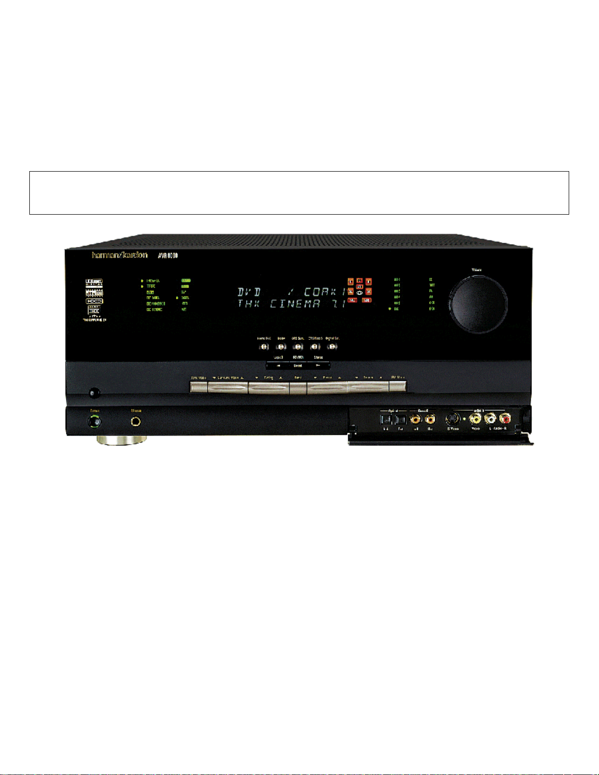
harman/kardon
AVR8000
A/V DOLBY DIGITAL RECEI VER
SERVICE MANUAL
ESD W ARNING………………………….…….2
LEAKAGE TESTING……………….....……....3
BASIC SPECIFICATIONS…………….….…..4
FRONT PANEL CONTROLS…………..…….5
FRONT PANEL DISPLAY…………………….7
REAR PANEL CONNECTIONS……..….……8
REMOTE CONTROL FUNCTIONS…….…..10
T R O U B L E S H O O T IN G G U I D E ……………..……14
PROCESSOR RESET……………………….14
BULLETIN HK2002-04………..………….….15
BULLETIN HK2004-01………..………….….17
TECH TIP HKTT2002-02…………….…..….19
TECH TIP HKTT2003-01………..…….…….22
harman/kardon, Inc.
250 Crossways Park Dr.
CONTENTS
DC OFFSET ADJUSTMENT………………23
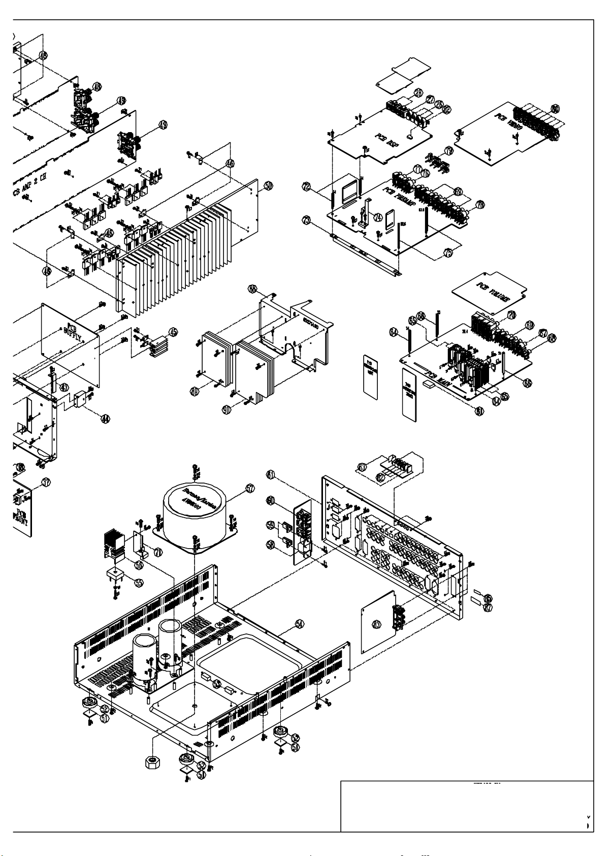
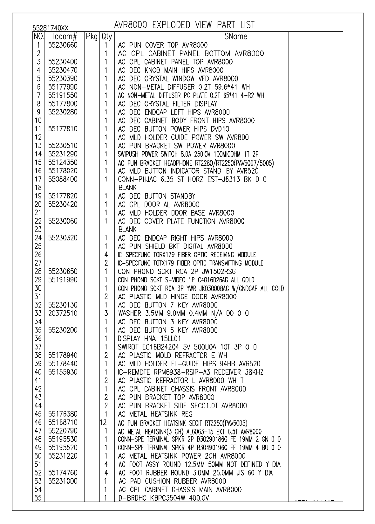
EXPLODED VIEW………………………….24
EXPLODED VIEW PARTS LIST………….27
DISASSEMBLY TIPS…………..……….….29
REPLACING IC701……………………..….36
ELECTRICAL PARTS LIST………..…..….37
BLOCK DIAGRAM…………………………120
PCB DRAWINGS……………………..…...121
SEMICONDUCTOR PINOUTS……..……156
SCHEMATICS……………………..…...….208
WIRING DIAGRAM………………………..241
PACKING…………………………………..242
Woodbur y, New York 11797 Rev10 7/ 2005

AVR8000 harman/kardon
2
Some semiconductor (solid state) devices can be damaged easily by static electricity. Such components commonly are called
Electrostatically Sensitive (ES) Devices. Examples of typical ES devices are integrated circuits and some field effect transistors and
semiconductor "chip" components.
The following techniques should be used to help reduce the incidence of component damage caused by static electricity.
1. Immediately before handling any semiconductor component or semiconductor-equipped assembly, drain off any electrostatic charge on
your body by touching a known earth ground. Alternatively, obtain and wear a commercially available discharging wrist strap device,
which should be removed for potential shock reasons prior to applying power to the unit under test.
2. After removing an electrical assembly equipped with ES devices, place the assembly on a conductive surface such as aluminum foil, to
prevent electrostatic charge build-up or exposure of the assembly.
3. Use only a grounded-tip soldering iron to solder or unsolder ES devices.
4. Use only an anti-static solder removal device. Some solder removal devices not classified as "anti-static" can generate electrical charges
sufficient to damage ES devices.
5. Do not use freon-propelled chemicals. These can generate electrical change sufficient to damage ES devices.
6. Do not remove a replacement ES device from its protective package until immediately before you are ready to install it. (Most replacement
ES devices are packaged with leads electrically shorted together by conductive foam, aluminum foil or comparable conductive material.)
7. Immediately before removing the protective material from the leads of a replacement ES device, touch the protective material to the
chassis or circuit assembly into which the device will be installed.
CAUTION :
8. Minimize bodily motions when handling unpackaged replacement ES devices. (Otherwise harmless motion such as the brushing together
or your clothes fabric or the lifting of your foot from a carpeted floor can generate static electricity sufficient to damage an ES devices.
Be sure no power is applied to the chassis or circuit, and observe all other safety precautions.
Each precaution in this manual should be followed during servicing.
Components identified with the IEC symbol in the parts list are special significance to safety. When replacing a component identified with
, use only the replacement parts designated, or parts with the same ratings or resistance, wattage, or voltage that are designated in the
parts list in this manual. Leakage-current or resistance measurements must be made to determine that exposed parts are acceptably
insulated from the supply circuit before retuming the product to the customer.
AVR8000
Before returning the unit to the user, perform the following safety checks :
1. Inspect all lead dress to make certain that
leads are not pinched or that hardware is not
lodged between the chassis and other metal
parts in the unit.
2. Be sure that any protective devices such as
nonmetallic control knobs, insulating fish-
papers, cabinet backs, adjustment and
compartment covers or shields, isolation
harman/kardon
resistor-capacity networks, mechanical
insulators, etc. Which were removed for the
servicing are properly re-installed.
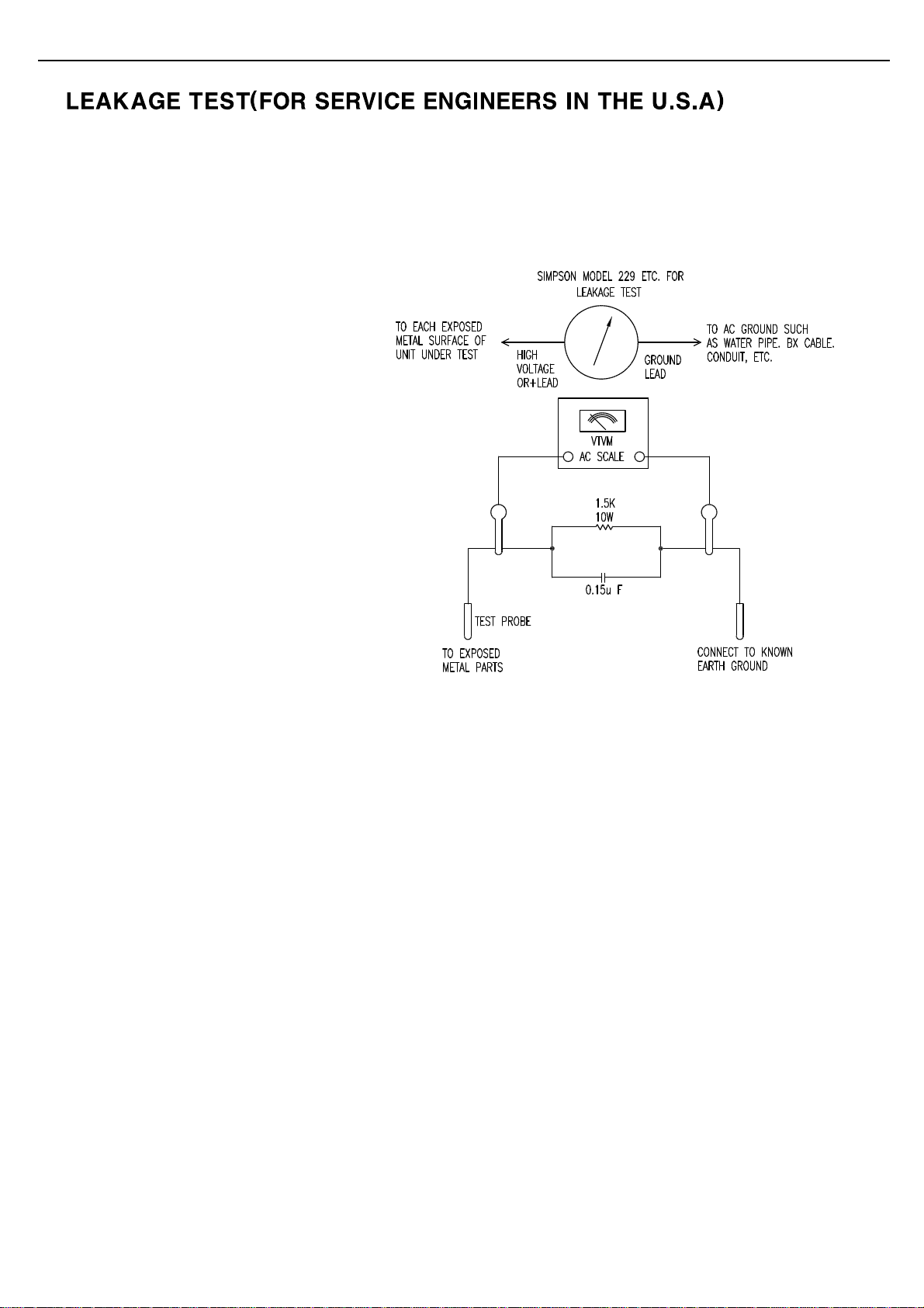
3. Be sure that no shock hazard exists ; check for leakage
current usingSimpson Model 229 Leakage Tester, standard
equipment item No. 21641, RCA Model WT540A or use
alternate method as follows : Plug the power cord directly
Into a 120 volt AC receptacle (do not use an Isolation
Transformer for this test). Using two clip leads, connect a
1500 ohms,10watt Resistor paralleledby a 0.15uFcapacitor,in series withall exposed metalcabinet parts anda known earthground, such
as a water pipe or conduit. Use a VTVM or VOM with 1000 ohms per volt, or higher sensitivity to measure the AC voltage drop across the
resistor. (See diagram) Move the resistor connection to each exposed metal part having a return path to the chassis (antenna, metal,
cabinet, screwheads, knobsand controlshafts, escutcheon, etc.) and measure theAC voltagedrop across the resistor. (This test shouldbe
performed withthe 0.35 volt RMS or more is excessiveand indicates apotential shock hazard which must be corrected beforereturning the
unit to the owner.
3
4 TECHNICAL SPECIFICATIONS
Technical Specifications
Audio Section
Stereo Mode
Continuous Average Power (FTC)
125 Watts per channel, 20Hz–20kHz,
@ < 0.07% THD, both channels driven into 8 ohms
Five-Channel Surround Modes
Power Per Individual Channel
Front L&R channels:
110 Watts per channel
@ < 0.07% THD, 20Hz–20kHz into 8 ohms
Center channel:
110 Watts @ < 0.07% THD, 20Hz–20kHz into 8 ohms
Surround channels:
110 Watts per channel
@ < 0.07% THD, 20Hz–20kHz into 8 ohms
Input Sensitivity/Impedance
Linear (High-Level) 200mV/47k ohms
Signal-to-Noise Ratio (IHF-A) 95dB
Surround System Adjacent Channel Separation
Analog Decoding 40dB
(Pro Logic II, etc.)
Dolby Digital (AC-3) 55dB
DTS 55dB
Frequency Response
@ 1W (+0dB, –3dB) 10Hz –100kHz
High Instantaneous
Current Capability (HCC) ±85 Amps
Transient Intermodulation
Distortion (TIM) Unmeasurable
Slew Rate 40V/µsec
FM T uner Section
Frequency Range 87.5–108.0MHz
Usable Sensitivity IHF 1.3 µV/13.2dBf
Signal-to-Noise Ratio Mono/Stereo 70/68dB
Distortion Mono/Stereo 0.2/0.3%
Stereo Separation 40dB @ 1kHz
Selectivity ±400kHz, 70dB
Image Rejection 80dB
IF Rejection 90dB
AM T uner Section
Frequency Range 520–1710kHz
Signal-to-Noise Ratio 45dB
Usable Sensitivity Loop 500µV
Distortion 1kHz, 50% Mod 0.8%
Selectivity ±10kHz, 30dB
Video Section
Television Format NTSC
Input Level/Impedance 1Vp-p/75 ohms
Output Level/Impedance 1Vp-p /75 ohms
Video Frequency Response
(Composite and S-Video) 10Hz–8MHz (–3dB)
Video Frequency Response
(Component) 10Hz–30MHz (–3dB)
General
Power Requirement AC 120V/60Hz
Power Consumption 119W idle, 694W maximum
(2 channels driven)
Trigger Output 6VDC @ 500ma
Dimensions (Max) Width 17.3 inches (440mm)
Height 7.65 inches (194mm)
Depth 20.5 inches (519mm)
Weight 53 lb (24.1 kg)
Depth measurement includes knobs, buttons and terminal connections.
Height measurement includes feet and chassis.
All features and specifications are subject to change without notice.
Harman Kardon is a registered trademark, and Power for the Digital Revolution is a trademark, of
Harman Kardon, Inc.
THX and THX Ultra are manufactured under license from Lucasfilm Ltd.
Lucasfilm, THX and THX Ultra are registered trademarks of Lucasfilm Ltd.
Surround EX is a jointly developed technology of THX and Dolby Laboratories, Inc., and is a
trademark of Dolby. Used under authorization.
is a trademark of Harman International Industries, Inc. (Patent No. 5,386,478).
*Manufactured under license from Dolby Laboratories.
“Dolby,”“Pro Logic,”“Pro Logic II” and the Double-D symbol are
trademarks of Dolby Laboratories. Confidential Unpublished
Works. ©1992–1999 Dolby Laboratories, Inc.All rights reserved.
DTS, DTS Surround, DTS-ES and DTS Neo:6 are registered trademarks of Digital Theater Systems, Inc.
UltraStereo is a trademark of UltraStereo Corp.
VMAx is a registered trademark of Harman International Industries, Inc., and is an
implementation of Cooper Bauck Transaural Stereo under patent license.
Logic 7 is a registered trademark of Lexicon, Inc.
Crystal is a registered trademark of Cirrus Logic Corp.
HDCD system manufactured under license from Pacific Microsonics, Inc.This product is
covered by one or more of the following: In the USA: 5,479,168; 5,638,074; 5,640,161; 5,808,574;
5,838,274; 5,854,600; 5,864,311; 5,872,531; and in Australia: 669114. Other patents pending.
AVR8000
harman/kardon
TM
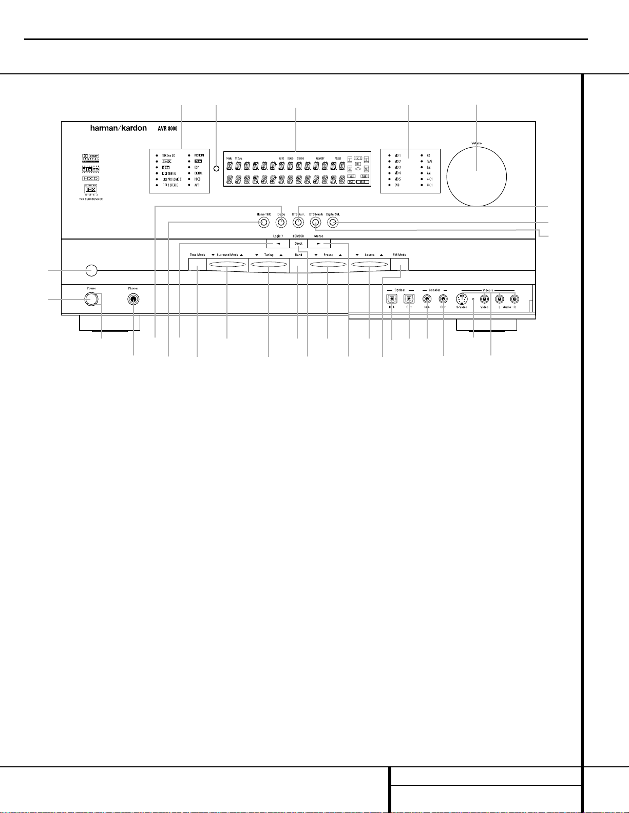
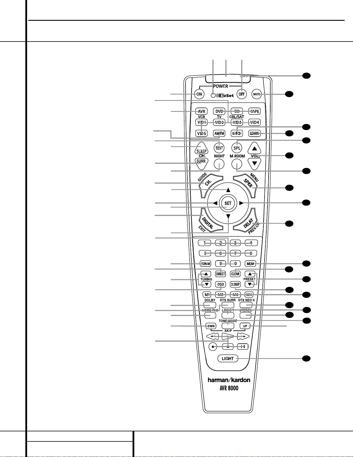
5 FRONT PANEL CONTROLS
1 Main Power Switch: Press this button
to apply power to the AVR 8000. When the
switch is pressed in, the unit is placed in a
Standby mode, as indicated by the amber
Power Indicator 3 surrounding the
System Power Control 2. This button
MUST be pressed in to operate the unit. To
turn the unit off and prevent the use of the
remote control, this switch should be pressed
until it pops out from the front panel so that
the word “OFF” may be read at the top of
the switch.
NOTE:This switch is normally left in the “ON”
position.
2 System Power Control: When the Main
Power Switch
1
is “ON,” press this button to
turn on the AVR 8000; press it again to turn the
unit off. Note that the
Power Indicator
3
surrounding the switch will turn green when
the unit is on.
3 Power Indicator:This LED will be lit in
amber when the unit is in the Standby mode to
signal that the unit is ready to be turned on.
When the unit is in operation, the indicator will
turn green.
4 Headphone Jack:This jack may be used to
listen to the AVR 8000’s output through a pair
of headphones. Be certain that the headphones
have a standard
1
/4" stereo phone plug. Note
that the main room speakers will automatically
be turned off when the headphone jack is
in use.
5 Dolby Mode Selector: Pressing this
selector button cycles the AVR through the
various Dolby surround modes.The first press
of the button switches the surround mode to
the last Dolby surround mode that was in use.
The choice of modes available will vary based on
the type of input source (digital or analog) and
the number of speaker channels your system is
configured for.
6 Home THX Mode Selector: Press this
button to select Home THX processing.The
choice of THX modes will vary according to
the type of input source and program material
(Dolby Digital, DTS 5.1, DTS 6.1 or analog), and
the number of speakers in your system. In some
cases the system will auto-default to the THX
Surround EX or THX Cinema mode, while in
other cases you will have a choice of modes.
7 Logic 7 Mode Selector/‹Button: This
button has two functions: In normal use, press
it to select one of the Logic 7 modes.When an
adjustment is being made using using the
Front Panel Controls
1 Main Power Switch
2 System Power Control
3 Power Indicator
4 Headphone Jack
5 Dolby Mode Selector
6 Home THX Mode Selector
7 Logic 7 Mode Selector/‹Button
8 Tone Mode
9 DSP Surround Mode Selector
) Tuning Selector
! Tuner Band Selector
@ 6Ch/8Ch Direct Button
# Preset Station Selector
$ Stereo Mode Selector/›Button
% Input Source Selector
^ FM Mode Selector
& Optical Digital 4 Input Jack
* Optical Digital 4 Output Jack
( Coaxial Digital 4 Input Jack
Ó Coaxial Digital 4 Output Jack
Ô Input/Output Status Indicator
Video 5 Input Jacks
Ò DTS Neo:6 Mode Selector
Ú Digital Select Button
Û DTS Surround Mode Selector
Ù Volume Control
ı Input Indicators
ˆ Main Information Display
˜ Remote Sensor Window
¯ Surround Mode/Bitstream Indicators
2
4
7
9
@
Ú
ı
¯
Û
Ù
1
3
5
6
8
)
!
#
$
%
^
&
Ó
*
(
Ô
Ò
ˆ
˜
AVR8000
harman/kardon
6 FRONT PANEL CONTROLS
Front Panel Controls
Digital Select Button Ú, this button may be
pressed to scroll through the available options.
8 Tone Mode: This button controls the tone
control settings, enabling adjustment of the bass
and treble boost/cut or the removal of the tone
controls from the signal path. The first press of
the button displays a
TONE IN message in
the
Main Information Display ˆ. If you
wish to take the tone controls to “flat,” without
any treble or bass alteration, press the
‹
or
›
Selector Buttons 7$ so that TONE
OUT
appears in the Lower Display Line B.
To change the tone settings, press the button
until either
TREBLE or BASS appears in
the
Lower Display Line B as desired, and
then press the
‹
or ›Selector Buttons
7$ to increase or decrease the setting. Note
that the Tone settings apply only to the front
left and right speakers, and they are not in
effect when a THX mode is in use.
9 DSP Surround Mode Selector: Press this
button to select the following DSP Surround
Modes: Hall 1, Hall 2 or Theater. (See page 28
for more information about surround modes.)
) Tuning Selector: Press the left side of the
button to tune lower-frequency stations and the
right side of the button to tune higher-frequency
stations.When a station with a strong signal
is reached, the
TUNED Indicator I will be lit
in the
Main Information Display ˆ.
To tune manually, tap the button lightly and
note that the tuner will step up one frequency
increment per button press.When the button is
held for a few seconds you will note that the
unit will quickly search the frequency band.
Release it once the fast tuning starts; the tuner
will automatically scan for the next station with
an acceptable signal and then stop.
! Tuner Band Selector: Pressing this but-
ton will automatically switch the AVR 8000 to
the Tuner mode. Pressing it again will switch
between the AM and FM frequency bands. (See
page 33 for more information on the tuner.)
@ 6Ch/8Ch Direct Button: Press this button
to select the 6-Channel Direct or 8-Channel
Direct inputs as the AVR 8000’s source.
# Preset Station Selector: Press this
button to scroll up or down through the list or
stations that have been entered into the preset
memory. (See pages 33 and 34 for more information on tuner programming.)
$ Stereo Mode Selector/›Button:
Pressing this selector button cycles through the
stereo modes, and it is also used to turn off all
surround processing and place the unit in a traditional two-channel Stereo mode.The first
press selects 5-Channel Stereo, the next press
selects 7-Channel Stereo, and the third press
selects “SURROUND OFF,” which is true Stereo.
% Input Source Selector: Press this button
to change the input by scrolling up or down
through the list of input sources.
^ FM Mode Selector:Press this button to
select Auto or Manual tuning.When the button
is pressed so that the
AUTO IndicatorJ
lights, the tuner will search for the next station
with an acceptable signal when the
Tuning
Selector
)uéis pressed. When the but-
ton is pressed so that the
AUTO IndicatorJ
is not lit, each press of the Tuning Selector
)uéwill increase the frequency. (See
page 33 for more information on using the
tuner.)
NOTE:The front panel digital audio, video and
analog audio input and output jacks are normally concealed behind a drop-down door in the
lower right corner of the front panel. To access
these jacks, open the panel door by gently
pulling down the upper right corner of the door
as indicated by “PULL/OPEN.”
& Optical Digital 4 Input Jack: Connect the
optical digital output of an audio or video product to this jack.
* Optical Digital 4 Output Jack:Connect
this jack to the optical digital input of a digital
recorder to send a feed of the digital output
when a PCM digital input source is in use by
the AVR 8000.
( Coaxial Digital 4 Input Jack:Connect the
output of a digital audio source to this jack.
Ó Coaxial Digital 4 Output Jack:Connect
this jack to the coaxial digital input of a digital
recorder to send a feed of the digital output
when a PCM digital input source is in use by
the AVR 8000.
Ô Input/Output Status Indicator:This LED
indicator will normally light green to show that
the front panel
Video 5 Input Jacks are
operating as inputs.When these jacks are
configured for use as an output, the indicator
will turn red to show that the jack may be used
for recording. (See page 34 for more information
on configuring the front panel jacks as outputs,
rather than inputs.)
Video 5 Input Jacks: These audio/video
jacks may be used for temporary connection to
video games or portable audio/video products
such as camcorders and portable audio players.
Ò DTS Neo:6 Mode Selector: Pressing this
button selects one of the DTS Neo:6 modes.The
first press selects the Neo:6 Movies mode, and
a second press will select the Neo:6 Music
mode. (See page 28 for more information on
the Neo:6 modes.)
Ú Digital Select Button:When playing a
source that has a digital output, press this
button to select between the
Optical &e
and Coaxial (b Digital inputs. (See page
31 for more information on digital audio.)
Û DTS Surround Mode Selector: Pressing
this selector button cycles the AVR through the
DTS surround modes.The choice of available
DTS modes will vary according to the type of
program source material (DTS 5.1 or DTS 6.1)
and whether your system is configured for 5.1
or 6.1/7.1 channel operation.
Ù Volume Control:Turn this knob clockwise
to increase the volume, counterclockwise to
decrease the volume. If the AVR 8000 is muted,
adjusting volume control will automatically
release the unit from the silenced condition.
ı Input Indicators: A green LED will light
to the left of the input that is currently the
input source for the AVR 8000.
ˆ Main Information Display:This display
delivers messages and status indications to
help you operate the receiver. (See page 7
for a complete explanation of the Information
Display.)
˜ Remote Sensor Window:The sensor
behind this window receives infrared signals
from the remote control. Aim the remote at this
area and do not block or cover it unless an
external remote sensor is installed.
¯ Surround Mode/Bitstream Indicators:
These LEDS will light to show the surround
mode and digital bitstream in use. Note that
depending on the specific combination of input
sources and surround mode selected, more
than one indicator may light. (See page 32 for
more information.)
AVR8000
harman/kardon
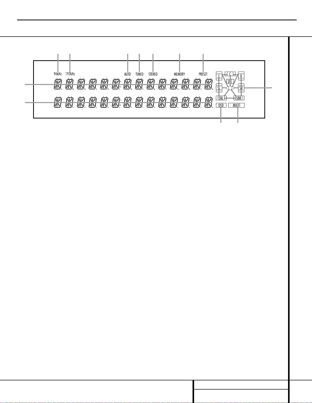
7 FRONT PANEL INFORMATION DISPLAY
Front Panel Information Display
A
B
D
E
KL
F
H
I
J
C
G
A Upper Display Line
B Lower Display Line
C OSD Indicator
D Multiroom Indicator
E Speaker/Channel Input Indicators
F PRESET Indicator
G MEMORY Indicator
H STEREO Indicator
I TUNED Indicator
J AUTO Indicator
K 192kHz Indicator
L 96kHz Indicator
A Upper Display Line: Depending on the unit’s
status, a variety of messages will appear here. In
normal operation, the current input source name
will appear on this line.
B Lower Display Line: Depending on the
unit’s status, a variety of messages will appear
here. In normal operation, the current surround
mode name will appear on this line.
C OSD Indicator:When the OSD system is in
use, this indicator lights to remind you that the
other indicators in this display do not function
when the On-Screen Display is being used.
D Multiroom Indicator:This indicator lights
when the multiroom system is active. Note that
it will remain lit when the multiroom system is
in use even though the main room system is in
the Standby mode and all other indicators are
dark. (See page 38 for more information on the
Multiroom system.)
E Speaker/Channel Input Indicators:These
indicators are multipurpose, indicating either the
speaker type selected for each channel or the
incoming data-signal configuration.The left,
center, right, right surround and left surround
speaker indicators are composed of three boxes,
while the subwoofer is a single box. The center
box lights when a “Small” speaker is selected,
and the two outer boxes light when “Large”
speakers are selected.When none of the boxes
are lit for the center, surround or subwoofer
channels, no speaker has been selected for one
of those positions. (See page 21 for more information on configuring speakers.) The letters
inside each of the center boxes display the active
input channels. For standard analog inputs, only
the L and R will light, indicating a stereo input.
When a digital source is playing, the indicators
will light to display the channels being received
at the digital input. When the letters flash, the
digital input has been interrupted. (See pages
25 & 32 for more information on the Channel
Indicators.)
F PRESET Indicator:This indicator lights
when the tuner is in use to show that the
present number for the current station being
listened to appears in the Upper Display Line.
(See page 34 for more information on tuner
presets.)
G MEMORY Indicator: This indicator flashes
when entering presets and other information
into the tuner’s memory.
H STEREO Indicator:This indicator lights
when an FM station is being tuned in stereo.
I
TUNED Indicator:
This indicator lights when
a station is being received with sufficient signal
strength to provide acceptable listening quality.
J AUTO Indicator:This indicator lights when
the tuner’s Auto mode is in use.
K 192kHz Indicator: This indicator lights
when the input source has a 192kHz bit rate.
L 96kHz Indicator: This indicator lights
when the input source has a 96kHz bit rate.
AVR8000
harman/kardon
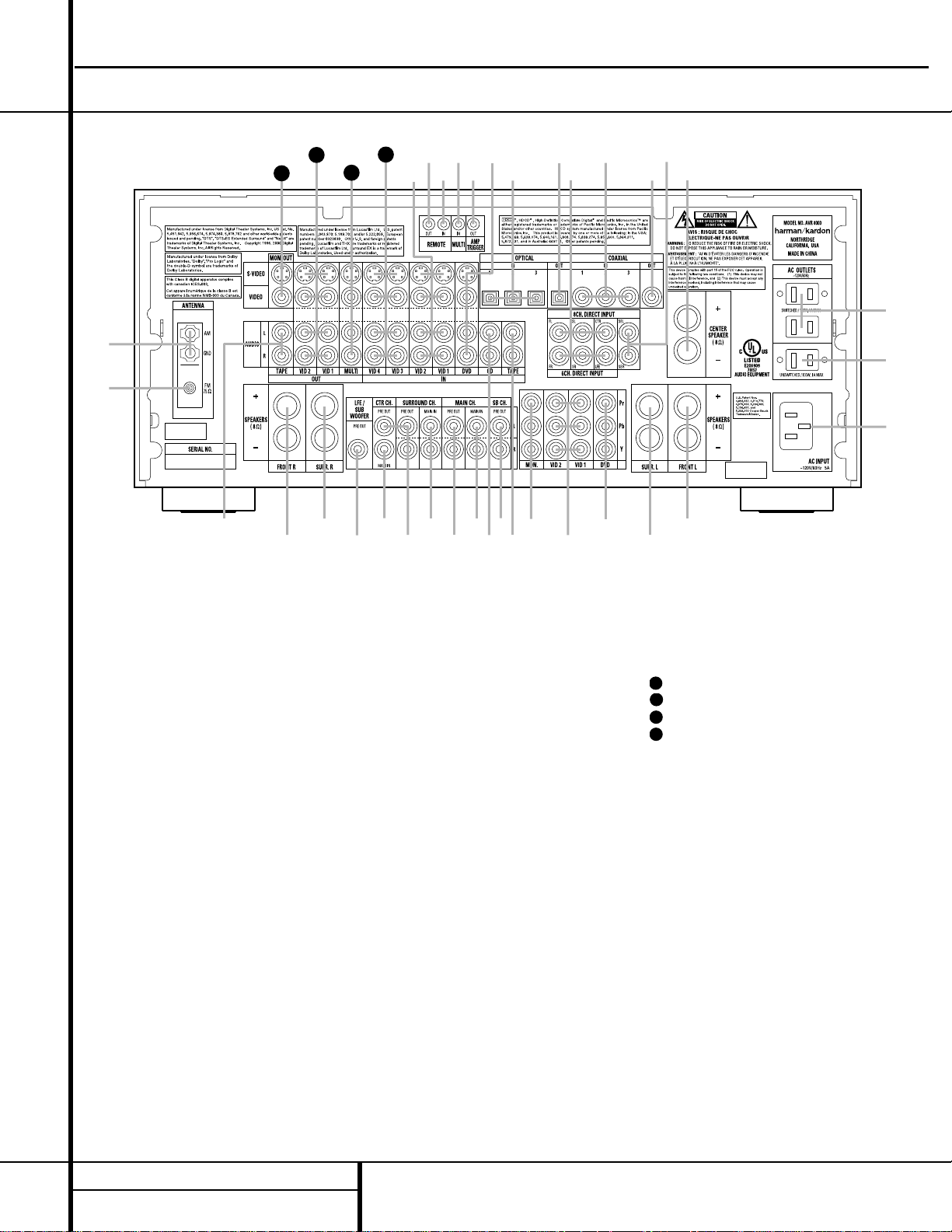
8 REAR PANEL CONNECTIONS
¡ AM Antenna:Connect the AM loop antenna
supplied with the receiver to these terminals. If an
external AM antenna is used, make connections
to the
AM and GND terminals in accordance
with the instructions supplied with the antenna.
™ FM Antenna: Connect the supplied indoor or
an optional external FM antenna to this terminal.
£ Tape Outputs: Connect these jacks to the
RECORD/INPUT jacks of an audio recorder.
¢ Front Speaker Outputs: Connect these
outputs to the matching + or – terminals on
your left and right speakers.When making
speaker connections always make certain to
maintain correct polarity by connecting the
color-coded (white for front left and red for
front right) (+) terminals on the AVR 8000 to
the red (+) terminals on the speakers and the
black (–) terminals on the AVR 8000 to the
black (–) terminals on the speakers. See page
15 for more information on speaker polarity.
∞ Surround Speaker Outputs: Connect
these outputs to the matching + and – terminals on your surround channel speakers. In conformance with the new CEA color code specification, the Blue terminal is the positive, or “+”
terminal that should be connected to the red
(+) terminal on the Surround Left speaker with
older color coding, while the Gray terminal
should be connected to the red (+) terminal on
the Surround Right speaker with the older color
coding. Connect the black (–) terminal on the
AVR to the matching black negative (–) terminals for each surround speaker. (See page 15
for more information on speaker polarity.)
§ Subwoofer Output: Connect this jack to
the line-level input of a powered subwoofer. If
an external subwoofer amplifier is used, connect this jack to the subwoofer amplifier input.
¶ Amplifier Inputs: When the jumper pins
that link the
Preamp Outputs • with these
inputs are removed, these jacks may be used to
connect an external source or the AVR 8000’s
multiroom system to the internal amplifiers.
• Main Channel Preamp Outputs: When
the jumper pins that link the
Amplifier Inputs
¶ with these outputs are removed, these jacks
may be connected to an external power amplifier.
ª CD Inputs: Connect these jacks to the out-
put of a compact disc player or CD changer.
Rear Panel Connections
∞
ª
⁄
‚
‹
fi
fl
‡
a
c °
·
b
d
e
f
gi
j
§
31
32
h
k
34
•¶•
¶
¶
¤
›
¡
™
£
¢
¢
∞
33
¡ AM Antenna
™ FM Antenna
£ Tape Outputs
¢ Front Speaker Outputs
∞ Surround Speaker Outputs
§ Subwoofer Output
¶ Amplifier Inputs
• Main Channel Preamp Outputs
ª CD Inputs
‚ Surround Back Preamp Outputs
⁄ Tape Inputs
¤ Component Video Outputs
‹ Video 1/Video 2 Component Video Inputs
› DVD Component Video Inputs
fi AC Power Cord Jack
fl Unswitched AC Accessory Outlet
‡ Switched AC Accessory Outlets
° Center Speaker Outputs
· 8-Channel Direct Inputs
a Coaxial Digital Audio Output
b Coaxial Digital Inputs
c 6-Channel Direct Inputs
d Optical Digital Audio Output
e Optical Digital Inputs
f DVD Inputs
g Amplifier Trigger Jack
h Multizone IR Input
i Remote IR Input
j Remote IR Output
k Video 1/Video 2 Inputs
Video 3/Video 4 Inputs
Multizone Outputs
Video 1/Video 2 Outputs
Video Monitor Outputs
AVR8000
harman/kardon
31
32
33
34
9 REAR PANEL CONNECTIONS
Rear Panel Connections
‚ Surround Back Preamp Outputs:When
the AVR is used in the 6.1 or 7.1 configuration,
connect these jacks to an optional, external
power amplifier to power the Surround Back
Channels.
⁄ Tape Inputs: Connect these jacks to the
PLAY/OUT jacks of an audio recorder.
¤ Component Video Outputs: Connect
these outputs to the component video inputs of
a video projector or monitor. When a source
connected to one of the
Component Video
Inputs
‹› is selected the signal will be sent
to these jacks.
‹ Video 1/Video 2 Component Video
Inputs:
Connect the Y/Pr/Pb component video
outputs of an HDTV Set-top convertor, satellite
receiver, or other video source device with component video outputs to these jacks.
› DVD Component Video Inputs: Connect
the Y/Pr/Pb component video outputs of a DVD
player to these jacks.
fi AC Power Cord Jack: Connect the AC
Power cord to this jack when the installation is
complete.To ensure safe operation, use only
the power cord supplied with the unit. If a
replacement is required it must be of same type
and capacity.
fl Unswitched AC Accessory Outlet: This
outlet may be used to power any AC device.
The power will remain on at this outlet regardless of whether the AVR 8000 is on or off.
NOTE:The total power consumption of all
devices connected to the accessory outlets
should not exceed 100 watts.
‡ Switched AC Accessory Outlets: These
outlets may be used to power any device you
wish to have turned on when the AVR 8000 is
turned on with the
System Power Control
Button
2.
° Center Speaker Outputs: Connect these
outputs to the matching + and – terminals on
your center channel speaker. In conformance
with the new CEA color code specification, the
Green Terminal is the positive, or “+” terminal
that should be connected to the red (+) terminal on speakers with the older color coding.
Connect the black (–) terminal on the AVR to
the black negative (–) terminal on your speaker.
(See page 15 for more information on speaker
polarity.)
· 8-Channel Direct Inputs: When an
optional, external source with discrete 7.1 analog audio output capability such as a DVDAudio or SACD player is use, connect that unit’s
surround back output jacks here.
a Coaxial Digital Audio Output: Connect
this jack to the coaxial digital input of a
CD-R/RW,MiniDisc or other digital recorder.
b Coaxial Digital Inputs: Connect the coax
digital output from a DVD player, HDTV receiver,
the S/P-DIF output of a compatible computer
sound card playing MP3 files or streams, LD player
or CD player to these jacks.The signal may be
either a Dolby Digital signal, DTS signal or a standard PCM digital source. Do not connect the RF
digital output of an LD player to these jacks.
c 6-Channel Direct Inputs:When an
optional, external source with discrete 5.1
analog audio output capability such as a
DVD-Audio or SACD player is use, connect
that unit’s output jacks here.
NOTE:To assist in making the correct connections for multichannel input output and speaker
connections, all connection jacks and terminals
have been color coded in conformance with the
latest CEA standards as follows:
Front Left: White
Front Right: Red
Center: Green
Surround Left: Blue
Surround Right: Gray
Surround Back Left: Brown
Surround Back Right: Tan
Subwoofer: Purple
Digital Audio: Orange
Composite Video: Yellow
Component Video “Y”: Green
Component Video “Pr”: Red
Component Video “Pb”:Blue
d Optical Digital Audio Output: Connect
this jack to the optical digital input connector
on a CD-R/RW, MiniDisc or other digital
recorder.
e Optical Digital Inputs: Connect the opti-
cal digital output from a DVD player, HDTV
receiver, the S/P-DIF output of a compatible
computer sound card playing MP3 files or
streams, LD player or CD player to these jacks.
The signal may be either a Dolby Digital signal,
a DTS signal or a standard PCM digital source.
f DVD Inputs:Connect the analog left/right
audio and composite or S-Video output of a DVD
player or other video source to these jacks.
g Amplifier Trigger Jack: Connect this jack
to the compatible input trigger jack on a power
amplifier or other relay controlled device.The
connected product will turn on when the AVR is
turned on.
h Multizone IR Input: Connect the output of
an IR sensor in a remote room to this jack to
operate the AVR 8000’s multiroom control system.
i Remote IR Input: If the AVR 8000’s
front-panel IR sensor is blocked due to cabinet
doors or other obstructions, an external IR
sensor may be used. Connect the output of
the sensor to this jack.
j Remote IR Output: This connection per-
mits the IR sensor in the receiver to serve other
remote controlled devices. Connect this jack to
the “IR IN” jack on Harman Kardon (or other
compatible) equipment.
k Video 1/Video 2 Inputs: Connect the
left/right audio and composite or S-Video
PLAY/OUT jacks on a VCR or other video source
to these jacks.
Video 3/Video 4 Inputs: Connect the
left/right audio and composite or S-Video outputs of a video source such as a VCR, satellite
receiver, hard drive video recorder or other
device to these jacks.
Multizone Outputs: Connect these jacks
to the optional external audio power amplifier
and video distribution system that delivers the
source selected for multizone distribution.
Video 1/Video 2 Outputs: Connect the
left/right audio and composite or S-Video
Record/Input jacks on a VCR or camcorder to
these jacks.
Video Monitor Outputs: Connect these
jacks to the composite or S-Video input of a TV
monitor or video projector to view the on-screen
menus and the output of any standard video
source selected by the receiver’s video switcher.
AVR8000
harman/kardon
31
32
33
34
●
●
●
●
●
●
●
●
●
●
●
●
●
●
●
●
●
●
●
●
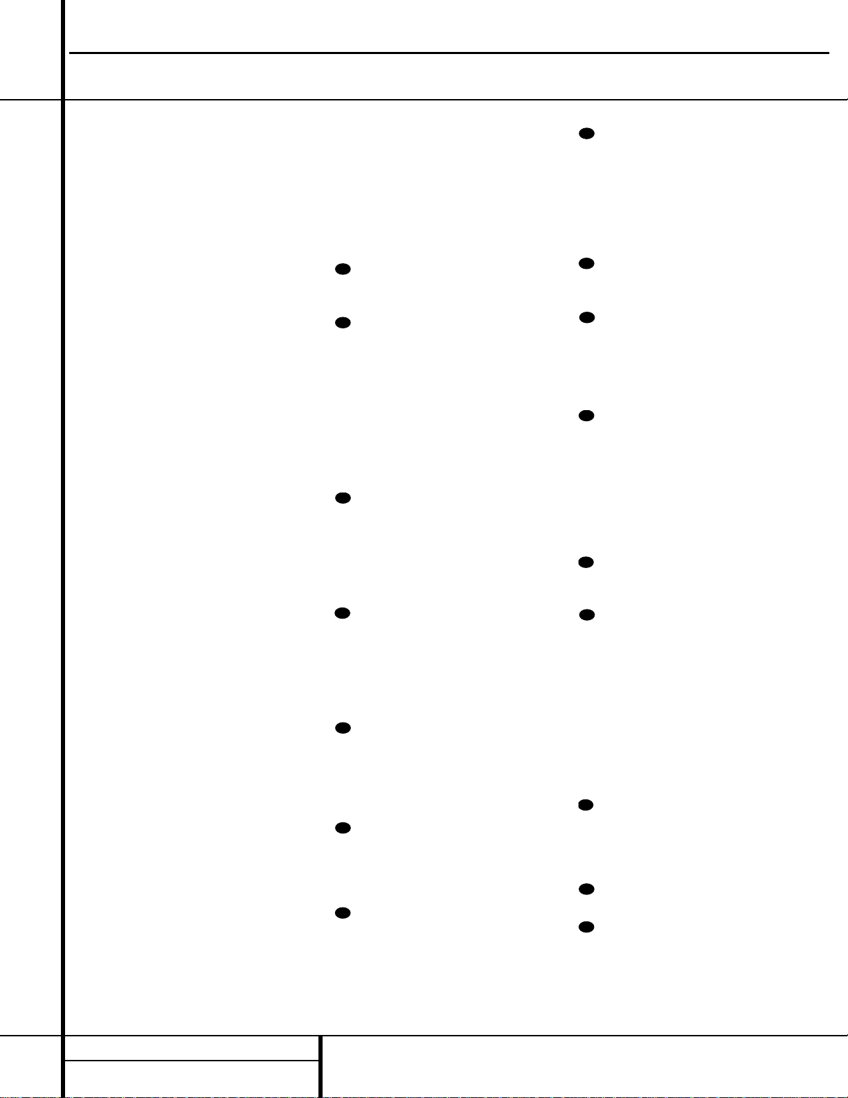
10 MAIN REMOTE CONTROL FUNCTIONS
a
bc
d
e
i
j
n
`
34
32
30
39
38
37
36
29
31
35
33
40
z
z
x
41
42
43
45
44
46
47
f
k
p
q
r
s
t
u
v
w
y
28
h
g
m
l
o
a Power Off Button
b IR Transmitter Window
c Program/SPL Indicator
d Power On Button
e Input Selectors
f AVR Selector
g AM/FM Tuner Select
h Test Button
i Sleep Button
j Surround Mode Selector
k Night Mode
l Channel Select Button
m⁄Button
n‹Button
o Set Button
p¤Button
q Digital Select
r Numeric Keys
s Tuner Mode
t Direct Button
u Tuning Up/Down
v OSD Button
w Dolby Mode Select Button
x DTS Digital Mode Selector
y THX Mode Select Button
z Skip Up/Down Buttons
` Transport Controls
28 Light Button
29
Tone Mode Button
30
Stereo Mode Select Button
31
Logic 7 Mode Select Button
32
DTS Neo:6 Mode Select
33
Macro Buttons
34
Disc Skip Button
35
Preset Up/Down
36
Clear Button
37
Memory Button
38
Delay/Prev. Ch.
39
›
Button
40
Speaker Select
41
Multiroom
42
Volume Up/Down
43
SPL Select
44 Learn Button
45
6-Channel/8-Channel Direct Input
46
Mute
47
EzSet Sensor Microphone
NOTE:The function names shown here are each button’s feature when used with the AVR 8000. Most buttons have additional functions when used with other
devices. See pages 44–45 for a list of these functions.
Main Remote Control Functions
AVR8000
harman/kardon
11 MAIN REMOTE CONTROL FUNCTIONS
Main Remote Control Functions
IMPORTANT NOTE:The AVR 8000’s remote
may be programmed to control up to eight
devices, including the AVR 8000. Before using
the remote, it is important to remember to
press the
Input Selector Button e that
corresponds to the unit you wish to operate.
In addition, the AVR 8000’s remote is shipped
from the factory programmed to operate the
AVR 8000 and most Harman Kardon CD or
DVD players and cassette decks.The remote is
also capable of operating a wide variety of other
products using the control codes that are part
of the remote. Before using the remote with
other products, follow the instructions on pages
39–43 to program the proper codes for the
products in your system.
It is also important to remember that many of
the buttons on the remote take on different
functions, depending on the product selected
using the Device Control Selectors.The descriptions shown here primarily detail the functions
of the remote when it is used to operate the
AVR 8000. (See page 44 for information about
alternate functions for the remote’s buttons.)
a Power Off Button: Press this button to
place the AVR 8000 or a selected device in the
Standby mode. Note that this will turn off the
main room functions, but if the Multiroom system is activated, it will continue to function.
b IR T ransmitter W indow:Point this win-
dow towards the AVR 8000 when pressing buttons on the remote to make certain that infrared
commands are properly received.
c Program/SPL Indicator:This three-color
indicator is used to guide you through the
process of programming the remote or learning
commands from a remote into the AVR 8000’s
remote code memory and it is also used as a
level indicator when using the remote’s EzSet
capabilities. (See page 24 for more information
on setting output levels, and see page 39 for
information on programming the remote.)
d Power On Button: Press this button to
turn on the power to a device selected by pressing one of the
Input Selectors ef.
e Input Selectors: Pressing one of these
buttons will perform three actions at the same
time. First, if the AVR 8000 is not turned on,
this will power up the unit. Next, it will select
the source shown on the button as the input to
the AVR 8000. Finally, it will change the remote
control so that it controls the device selected.
After pressing one of these buttons you must
press the
AVR Selector Button f again to
operate the AVR 8000’s functions with the
remote.
f AVR Selector: Pressing this button will
switch the remote so that it will operate the
AVR 8000’s functions. If the AVR 8000 is in the
Standby mode, it will also turn the AVR 8000 on.
g AM/FM Tuner Select: Press this button to
select the AVR 8000’s tuner as the listening
choice. Pressing this button when the tuner is
already in use will select between the AM and
FM bands.
h Test Button: Press this button to begin
the sequence used to calibrate the AVR 8000’s
output levels. (See page 24 for more information
on calibrating the AVR 8000.)
i Sleep Button: Press this button to place
the unit in the Sleep mode.After the time
shown in the display, the AVR 8000 will automatically go into the Standby mode. Each press
of the button changes the time until turn-off in
the following order:
Once the sleep timer has been activated, note
that the
Main Information Display ˆ will
dim to half brightness. Note that this button is
also used to change channels on your TV when
the TV is selected.
When the AVR 8000 remote is being programmed with the codes to operate another
device, this button is also used in the “Auto
Search” process. (See page 39 for more information on programming the remote.)
j Surround Mode Selector: Press this
button to begin the process of changing the
surround mode.After the button has been
pressed, use the
⁄/¤
Buttons mp to
select the desired surround mode. (See page 28
for more information.) Note that this button is
also used to tune channels when the TV is
selected using the device
Input Selector
e. When the AVR 8000 remote is being programmed with the codes of another device, this
button is also used in the “Auto Search”
process. (See page 39 for more information on
programming the remote.)
k Night Mode: Press this button to activate
the Night mode.This mode is available in specially encoded digital sources, and it preserves
dialog (center channel) intelligibility at low
volume levels.
l Channel Select Button:This button is
used to start the process of setting the AVR 8000’s
output levels to an external source. Once this
button is pressed, use the
⁄/¤
Buttons
mp to select the channel being adjusted,
then press the
Set Button o, followed by
the
⁄/¤
Buttons
mp again, to change the
level setting. (See page 34 for more information.)
m
⁄
Button:This multipurpose button is
used to change or scroll up through the list of
items in the on-screen menus, make configuration settings such as digital inputs or delay
timing, or to select surround modes.When
changing a setting, first press the button for the
function or setting to be changed (e.g., press
the
Surround Mode Selector j to select a
sound field mode or the
Digital Select
Button
q to change a digital input) and
then press this button to scroll through the list
of options or to increase a setting. The sections
in this manual describing the individual features
and functions contain specific information on
using this button for each application.
n
‹
Button:This button is used to change
the menu selection or setting during some of
the setup procedures for the AVR 8000.
o Set Button:This button is used to enter
settings into the AVR 8000’s memory. It is also
used in the setup procedures for delay time,
speaker configuration and channel output level
adjustment.
p
¤
Button:This multipurpose button is
used to change or scroll down through the
items in the on-screen menus, make configuration settings such as digital inputs or delay timing, or to select surround modes.When changing a setting, first press the button for the function or setting to be changed and then press
this button to scroll down through the list of
options or to decrease a setting. The sections in
this manual describing the individual features
and function contain specific information on
using this button for each specific application.
q Digital Select: Press this button to assign
one of the digital inputs
&(be to a
source. (See page 31 for more information on
using digital inputs.)
r Numeric Keys:These buttons serve as a
ten-button numeric keypad to enter tuner preset
positions.They are also used to select channel
numbers when TV, Cable or SAT has been
selected on the remote, or to select track numbers on a CD, DVD or LD player, depending on
how the remote has been programmed.
90
min80min70min60min50min
40
min
30
min20min10min
OFF
AVR8000
harman/kardon
12 MAIN REMOTE CONTROL FUNCTIONS
Main Remote Control Functions
s Tuner Mode: Press this button when the
tuner is in use to select between automatic
tuning and manual tuning. When the button is
pressed so that the
AUTO Indicator J goes
out, pressing the
Tuning Buttons u)
≠
will move the frequency up or down in singlestep increments.When the FM band is in use,
pressing this button when a station’s signal is
weak will change to monaural reception. (See
page 33 for more information.)
t Direct Button: Press this button when
the tuner is in use to start the sequence for
direct entry of a station’s frequency. After pressing the button, simply press the proper
Numeric Keys r to select a station. (See
page 33 for more information on the tuner.)
u Tuning Up/Down:When the tuner is in
use, these buttons will tune up or down through
the selected frequency band. If the
Tuner Mode
Button
s^ has been pressed so that the
AUTOIndicator J is illuminated, pressing and
holding either of the buttons for three seconds
will cause the tuner to seek the next station with
acceptable signal strength for quality reception.
When the
AUTOIndicator J is NOT illumi-
nated, pressing these buttons will tune stations
in single-step increments. (See page 33 for more
information.)
v OSD Button: Press this button to activate
the On-Screen Display (OSD) system used to set
up or adjust the AVR 8000’s parameters.
w Dolby Mode Selector:This button is
used to select from among the available Dolby
Surround processing modes. Each press of this
button will select one of the Dolby Pro Logic II
modes or Dolby 3 Stereo.When a Dolby Digital
encoded source is in use, the Dolby Digital mode
may also be selected. (See page 28 for the available Dolby surround mode options.)
x DTS Digital Mode Selector:When a
DTS-encoded digital source is selected, each
press of this button will scroll through the available DTS modes.The specific choice of modes
will vary according to whether or not the source
material contains DTS-ES 6.1 Discrete encoding.
When a DTS source is not in use, this button has
no function. (See page 28 for the available DTS
Digital options.)
y THX Mode Select Button: Press this but-
ton to select the Home THX mode that is applicable to the input type and speaker configuration in use.
z Skip Up/Down Buttons: These buttons
don’t have a direct function with the AVR 8000,
but when used with a compatibly programmed
CD or DVD changer they will change the disc
currently being played in the changer.
` Transport Controls: These buttons do
not have any functions for the AVR 8000, but
they may be programmed for the forward/
reverse play operation of a wide variety of CD
or DVD players, and audio or video cassette
recorders. (See page 42 for more information.)
Light Button: Press this button to acti-
vate the remote’s backlight for ease of use in
darkened rooms.
Tone Mode Button: Press this button to
turn the controls off so that the output is “flat,”
or to boost or lower the tone modification. The
first press of this button shows whether the
tone controls are active or not. Subsequent
presses enable you to select the treble or bass
for change by pressing the
⁄/¤
Buttons
mp. Note that the tone controls only
change the output for the front left/right
speakers and they are not available when a
THX mode is in use.
Stereo Mode Select Button: Press this
button to select a stereo listening mode.The
first press of the button places the AVR in a
true, two-channel, left/right stereo mode with
no surround processing. The next press selects
either five-channel stereo or seven-channel
stereo, depending on the speaker configuration.
Logic 7 Mode Select Button: Press
this button to select a Logic 7 Mode.This
Harman proprietary process excels at converting
two channel stereo or matrix surround encoded
sources into a full five, six or seven channel
sound field. (See page 28 for the available
Logic 7 options.)
DTS Neo:6 Mode Select: Press this but-
ton to select a DTS Neo:6 Mode.These modes
take a two channel stereo or matrix surround
encoded source and create a full five-, six- or
seven-channel sound field. (See page 28 for the
available DTS Neo:6 options.)
Macro Buttons: Press these buttons
to store or recall a “Macro”, which is a
preprogrammed sequence of commands
stored in the remote. (See page 40 for more
information on storing and recalling macros.)
Disc Skip Button:This button has no
direct function for the AVR 8000 but is most
often used to change to the next disc in a CD
or DVD player when the remote is programmed
for that type of device. (See page 39 for more
information on using the remote with products
other than the AVR 8000.)
Preset Up/Down:When the tuner is
in use, press these buttons to scroll through the
stations programmed into the AVR 8000’s
memory.When some source devices, such as
CD players,VCRs and cassette decks, are selected using the device
Input Selectors e,
these buttons may function as Chapter Step or
Track Advance.
Clear Button: Press this button to clear
incorrect entries when using the remote to
directly enter a radio station’s frequency.
Memory Button: Press this button to
enter a radio station into the AVR 8000’s preset
memory. Once the
MEMORYIndicator G
flashes, you have five seconds to enter a preset
memory location using the
Numeric Keys
r. (See page 34 for more information.)
Delay/Prev Ch.: Press this button to
begin the process for setting the delay times
used by the AVR 8000 when processing surround sound. After pressing this button, the
delay times are entered by pressing the
Set Button o and then using the ⁄/
¤
Buttons mp to change the setting. Press
the
Set Button o again to complete the
process. (See page 24 for more information.)
›
Button: Press this button to change a
setting or selection when configuring many of the
AVR 8000’s settings.
Speaker Select: Press this button
to begin the process of configuring the
AVR 8000’s bass management system for use
with the type of speakers used in your system.
Once the button has been pressed, use the
⁄/¤
Buttons mp to select the channel
you wish to set up. Press the
Set Button o
and then select another channel to configure.
When all adjustments have been completed,
press the
Set Button o twice to exit the
settings and return to normal operation. (See
page 21 for more information.)
Multiroom: Press this button to activate
the multiroom system or to begin the process of
changing the input or volume level for the second zone. (See page 38 for more information on
the Multiroom system.)
Volume Up/Down:Press these buttons
to raise or lower the system volume.
SPL Select: This button activates the
AVR 8000’s EzSet function to quickly and
accurately calibrate the AVR 8000’s output
levels. Press and hold the button for three
seconds and then release it. Note that the
test tone will begin circulating, and the
AVR8000
harman/kardon
28
29
30
31
32
33
34
35
36
37
38
39
40
41
42
43
13 MAIN REMOTE CONTROL FUNCTIONS
Main Remote Control Functions
Program/SPL Indicator c will change
colors. During this sequence, EzSet will automatically adjust the output levels for all
channels until they are equal, as shown by the
Program/SPL Indicator c lighting green
for each channel. Press this button again when
the adjustment is complete to turn off the test
tone. (See pages 24 and 25 for more information on EzSet.)
Learn Button: Press this button to begin
the process of “learning” the codes from another
product’s remote into the AVR 8000’s remote.
(See page 39 for more information on using the
remote’s learning function.)
6-Channel/8-Channel Direct Input:
Press this button to select the device connected
to the
6-Channel Direct Inputs c or the
8-Channel Direct Inputs ·. (See page 35
for more information.)
Mute: Press this button to momentarily
silence the AVR 8000 or TV set being controlled, depending on which device has been
selected. When the AVR 8000 remote is being
programmed to operate another device,this button is pressed with the
Input Selector Button
e to begin the programming process. (See
page 39 for more information on programming
the remote.)
EzSetSensor Microphone: The sensor
microphone for the EzSet microphone is behind
these slots.When using the remote to calibrate
speaker output levels using EzSet, be sure that
you do not hold the remote in a way that covers these slots. (See pages 24 and 25 for more
information on using EzSet.)
AVR8000
44
45
46
47
harman/kardon
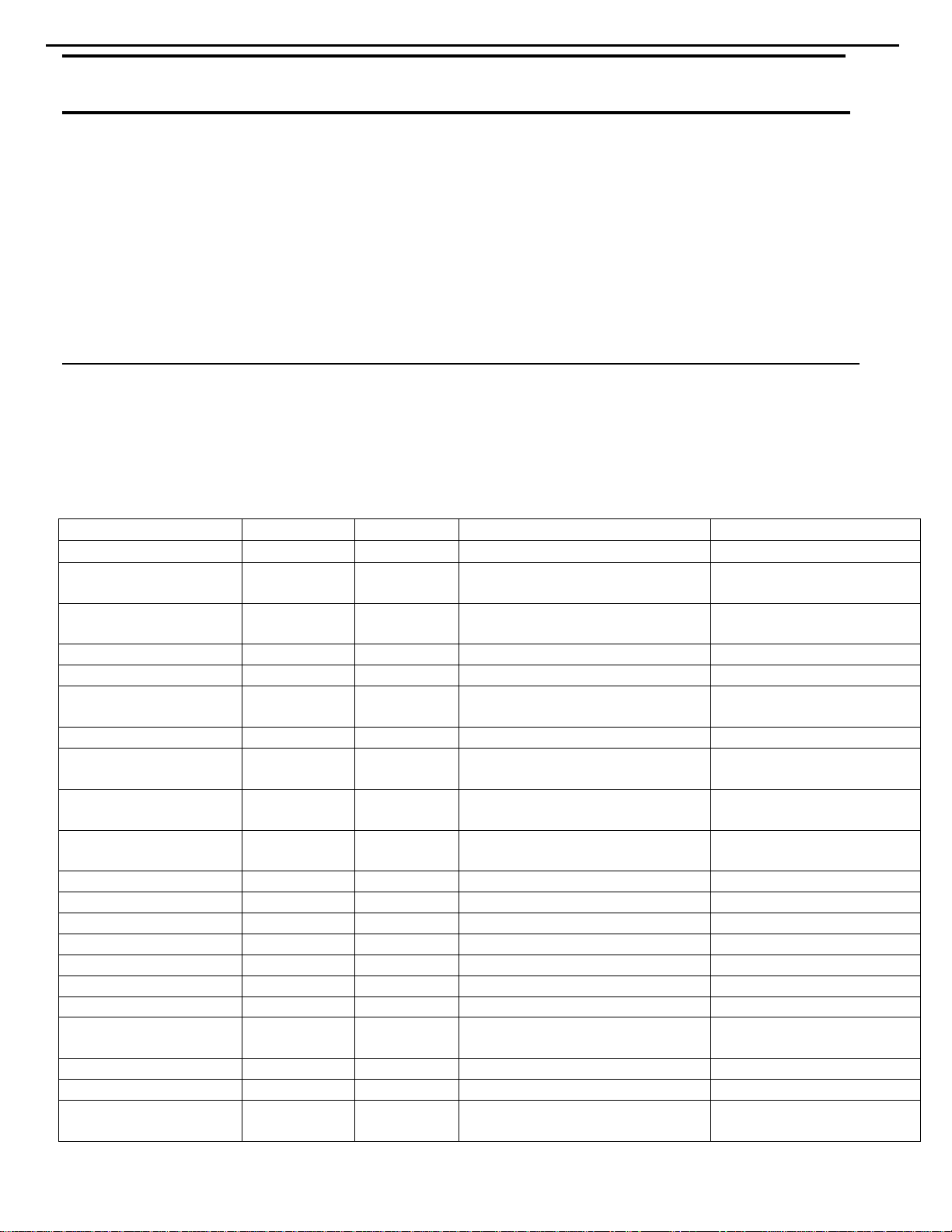
SYMPTOM CAUSE SOLUTION
Unit does not function when Main • No AC Power • Make certain AC power cord is plugged into
Power Switch is pushed a live outlet
• Check to see whether outlet is switch-controlled
Display lights, but no sound • Intermittent input connections • Make certain that all input and speaker connections
or picture are secure
•
Mute is on • Press Mute button
• Volume control is down • Turn up volume control
Unit turns on, but front panel • Display brightness is turned off • Follow the instructions in the Display Brightness section
display does not light up on page 36 so that the display is set to VFD FULL
No sound from any speaker; • Amplifier is in protection mode • Check speaker wire connections for shorts at receiver and
light around power switch is red due to possible short speaker ends
• Amplifier is in protection mode • Contact your local Harman Kardon service center
due to internal problems
No sound from surround or • Incorrect surround mode • Select a mode other than Stereo
center speakers • Input is monaural • There is no surround information from mono sources
• Incorrect configuration • Check speaker mode configuration
• Stereo or Mono program material • The surround decoder may not create center- or rear-channel
information from nonencoded programs
Unit does not respond to • Weak batteries in remote • Change remote batteries
remote commands • Wrong device selected • Press the AVR selector
• Remote sensor is obscured • Make certain front panel sensor is visible to remote
or connect remote sensor
Intermittent buzzing in tuner • Local interference • Move unit or antenna away from computers, fluorescent
lights, motors or other electrical appliances
Letters flash in the channel indicator • Digital audio feed paused • Resume play for DVD
display and digital audio stops • Check that Digital Input is selected
Processor Reset
In the rare case where the unit’s operation or
the displays seem abnormal, the cause may
involve the erratic operation of the system’s
memory or microprocessor.
To correct this problem, first unplug the unit
from the AC wall outlet and wait at least three
minutes. After the pause, reconnect the AC
power cord and check the unit’s operation. If
the system still malfunctions, a system reset
may clear the problem.
To clear the AVR 8000’s entire system memory
including tuner presets, output level settings,
delay times and speaker configuration data,
first put the unit in Standby by pressing the
System Power Control Button 2. Next,
press and hold the
Tone Mode 8 and the
FM Mode Selector ^ buttons for three
seconds.
The unit will turn on automatically and display
the
RESET message in the Main
Information Display
ˆ. Note that once you
have cleared the memory in this manner, it is
necessary to reestablish all system configuration
settings and tuner presets.
NOTE: Resetting the processor will erase any
configuration settings you have made for
speakers, output levels, surround modes, digital
input assignments as well as the tuner presets.
After a reset the unit will be returned to the
factory presets, and all settings for these items
must be reentered.
If the system is still operating incorrectly, there
may have been an electronic discharge or
severe AC line interference that has corrupted
the memory or microprocessor.
If these steps do not solve the problem, consult
an authorized Harman Kardon service center.
14 TROUBLESHOOTING GUIDE
Troubleshooting Guide
AVR8000
harman/kardon
AVR8000
15
harman/kardon
harman/kardon Service Bulletin
Service bulletin # H/K2002-04 April 2002 Warranty labor rate: MINOR repair
To: All harman/kardon Service Centers
Model: AVR8000
Subject: Idle Current Adjustment Procedure
In the event you receive an AVR8000 with the complaint “The receiver is overheating, or the protection
circuit is engaging, or intermittently shutting down after the unit warms up” the DC idle current should
be checked and adjusted as described below. Top cover may feel abnormally hot to the touch.
Synopsis: Set DC idle current of output devices by adjusting five potentiometers
Specialized equipment/parts needed:
Variable AC transformer (“Variac” type) to adjust and monitor AC line voltage.
Two pin harness plug to connect DMM to idle current test points. Order hk part# 55212910NR.
Note: Unit that no longer functions when cool may have damaged components: output transistors, resistors,
diodes, etc, in the output stage which must be replaced before performing adjustment so protection circuit is
not activated.
1) Unplug any external connected cables to the AVR8000.
2) Remove the top cover, (18) black Phillips screws.
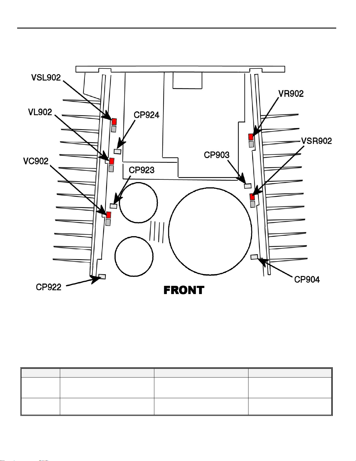
3) Locate the five idle current-current adjustment potentiometers (see illustration page 2). Facing the front of
the AVR8000, they are located on the left and right sides of the unit along the top of the vertical PCB’s.
They are also marked on the PCB’s “Idle-Adj.”
4) The white 2 pin Connectors (test points) and their related adjustment pots are referenced below. First,
with the unit turned OFF, adjust with a small screwdriver so that all idle current pots are “centered”.
Test Point (Check with DMM) Adjust Idle current Pot
CP903 Affected by VR902
CP904 Affected by VSR902
CP922 Affected by VC902
CP923 Affected by VL902
CP924 Affected by VSL902
Do not confuse the idle current adjustments with the DC offset adjustment pots which are located
directly adjacent to them !
5) Replace the top cover (no screws); turn unit ON. Unit should be connected to a “Variac” type (variable
transformer) adjusted to 120VAC. Let receiver idle with no load, no signal input, and volume control at
minimum (full CCW), for five minutes to stabilize the amplifiers.
6) Remove cover again. Plug in the two pin harness plug at first test point and connect to DMM set on the
mV scale. Check and adjust AC line voltage to 120 volts again if necessary. Using a non-metallic
screwdriver, adjust each of the idle current pots, one at a time, in the following manner: The final desired
voltage at each test point is 10.5 mV, but you should arrive at this voltage by reducing a higher amount in
25% increments with each adjustment, with the final adjustment set at 10.5 mV. This adjustment should
be made gradually in steps, so the amplifiers will have time to stabilize. Repeat this procedure at least
three additional times, each time replacing the top cover (no screws necessary), and letting unit idle
turned ON for at least five minutes between each adjustment. Monitor the AC line voltage and adjust to
120 volts when necessary.
7) If a wattmeter is available, total wattage drawn from line should be 165 to 170 watts at idle.
8) Replace the top cover and screws after the final adjustment.
AVR8000
16
harman/kardon
Model
AVR8000
AVR8000
Serial Number (120v)
TH0036-1001
to
TH0036-4101
TH0036-4102
and above
Status Action
DC idle current of output devices
may need adjustment
Preset at Factory NONE REQUIRED
Adjust DC idle current

AVR8000
harman/kardon
harman/kardon Service Bulletin
Service bulletin # H/K2004-01 Rev1 March 2004
To: All harman/kardon Service Centers
Model: AVR8000
Subject: DVD Surround Mode Switches to Stereo
W hen DVD soft ware is b eing m astered, the producer has the opt ion to choose w hich audio f orm ats are us ed, and
the time intervals when they present themselves. For example, a typical DVD may utilize Dolby Digital 2.0
(2 channel) audio format i n the initial screen. A typical first screen may include menu choic es such as: Special
Features, Audi o Setup, Directors C uts, and Play Movie. This remains on- screen until the user makes a selecti on,
and normal ly would be “Play Movie”. At this point, the p roducer may decide to
Dolby Digital 5.1. If this time interval is too short, as it is on a small number of DVD titles, the surround DSP
process or i n ear l y AVR8000’ s may stay in Dol b y Di gital 2.0 ( s ter eo) , r at her than sw i tc h to Dolb y Dig i tal 5.1 when the
prog ram b egins , even thoug h the fr ont panel i ndicators on the unit may imp ly 5.1 is in effect. In this condition, this
will not be a tru e stereo mode and music information will be lost, and not added to the stereo loudspeakers.
In the event you receive an AVR8000 A/V receiver with the complaint: “When I play a DVD with a player
that’s connected to the AVR8000 digital inputs, the receiver stays in stereo mode once the DVD starts
playing, when it should be playing Dolby Digital 5.1”, perform the modification below:
Synopsis: Change IC100 on the DSP sub-PCB.
CAUTION: IC100 is an electrostatically sensitive device and can be damaged by careless handling; follow
proper static control procedures to prevent damage to the module.
1) Unplug any external connected cables to the AVR8000, particularly the POWER cord.
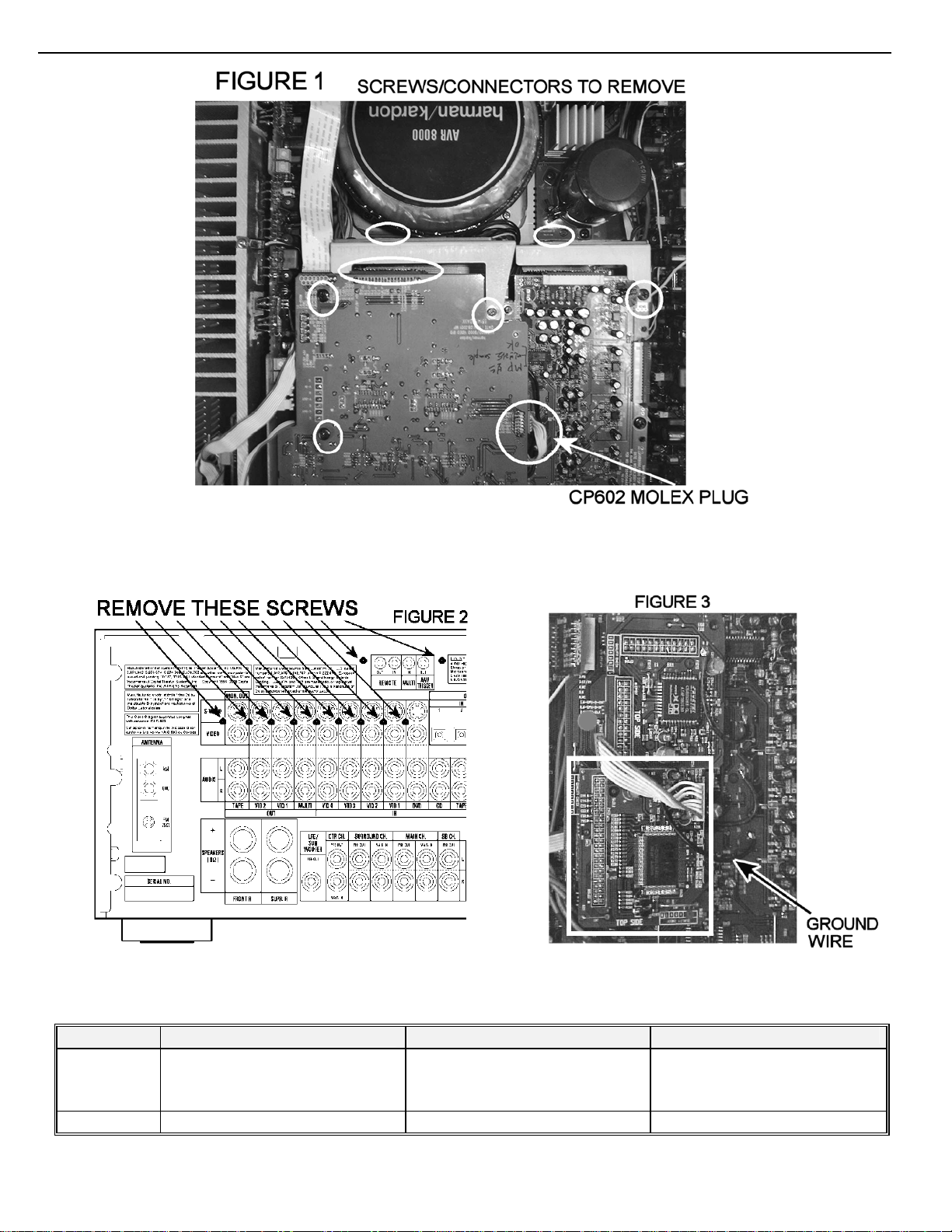
2) Remove the top cover, (18) Black Phillip s screws.
3) Locate and remove the metal shield located between the PCB’s and the power transformer (See figure 1);
remove th e (2) bottom Phillips screws first. A long shaft Ph illips screwdriver is required, and magnetic
blade preferred. Then remove the (2) Phillips upper screws; remove the shield from the unit.
4) At the rear of the AVR8000, remove the (2) black Phillips screws holding th e IR Remote PCB t o the rea r
cover; set the PCB aside, with cable st ill attached; remove the (9) black Phillips screws ho lding the V ideo
PCB to the rear cover. (See figure 2)
5) Remove the 7 conductor amber colored Molex plug (CP602) from the right side of the Video PCB.
6) Remove the fina l t op (2) Phillips screws holdin g the Video PCB on.
7) Push the narrow vertical connector PCB away from the rear of the Video PCB, disengaging it from the
Video PCB (and the Input PCB).
8) Lift the Video PCB, with ribbon cable attached, out of the unit and set it aside.
9) Carefully unplug and remove the IC100 module, pulling straight up; the connector and pins are on the left
side so more effort is required there.
10) Replace IC100 with h/k part# 55229550DPS; CAUTION – after replacement, make sure module is
inserted correctly – On PCB the lettering “TOP SIDE UP” should be facing the rear of the unit. Do not
force into place or bend pins, and make sure the socket is engaging all pins correctly.
11) Reassembly: follow instructions above in reverse order, assuring module, screws, molex connector,
vertical PCB, and shield/support is replaced. The metal shield has two “locator pins” at the bottom; make
sure they are replaced in the holes designed for them at the bottom of the chassis. Replace IR Remote
PCB and all screws at the rear of the unit; replace cover. When replacing the screws, use caution and do
not over-torque as you may strip the plastic receptacles.
12) Test the AVR8000 by re-connecting to the DVD player and playing the exact DVD disc that the problem
had occurred in, and assure the receiver stays in Dolby Digital 5.1 when the program is played.
Warranty labor rate: MINOR repair
switch from Dolby Digital 2.0 to
17
AVR8000
harman/kardon
Model
AVR8000
AVR8000 TH0036-02204 and above Modified by Factory None Required
Serial Number ( 120v)
TH0036-01001
to
TH0036-02203
Status Action
Surround mode switches to stereo
when playing certain DVD’s
Change IC100 module
Change in software from 5.0 to 5.1
18

AVR8000
19
harman/kardon
harman/kardon TECH TIPS
Troubleshooting tips and solutions to common service problems
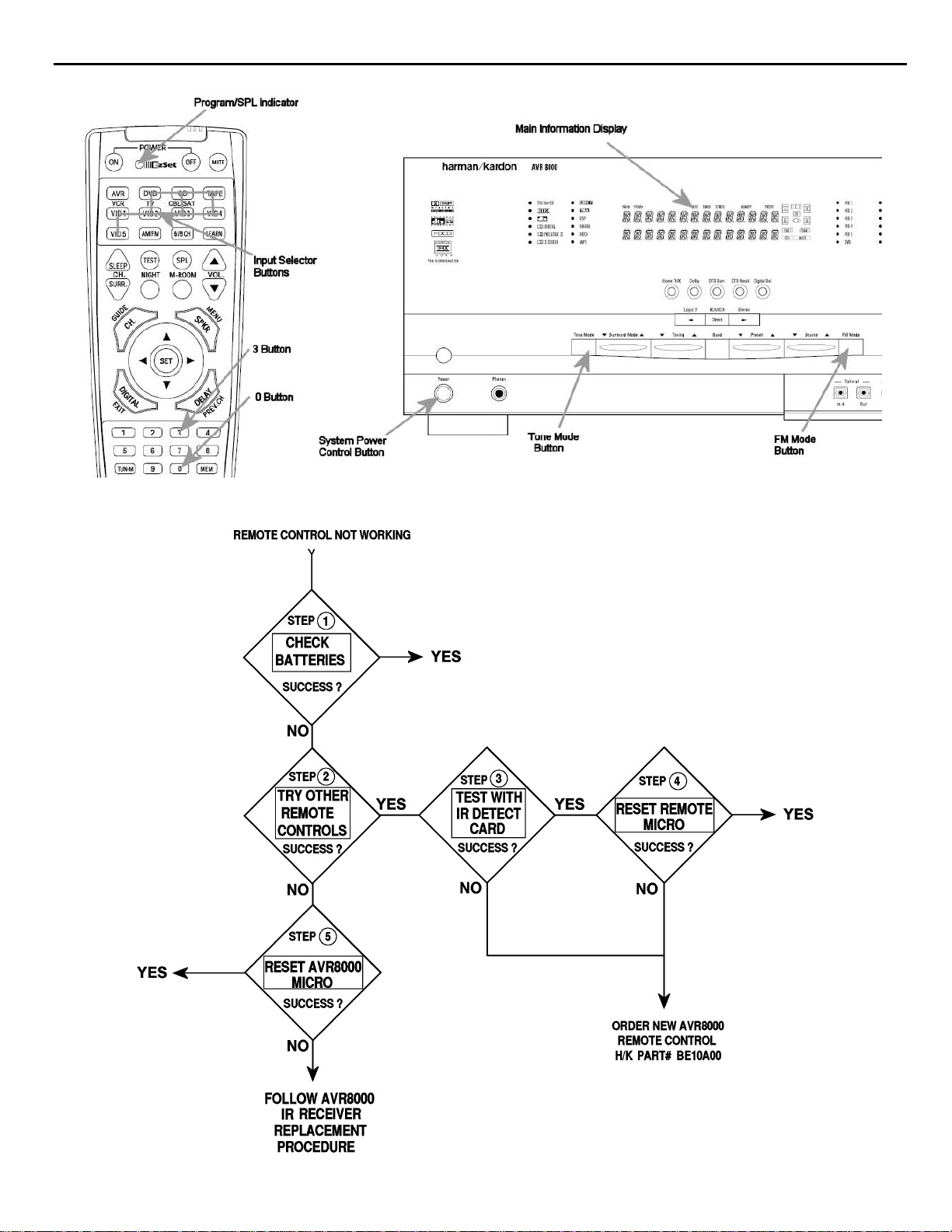
For models: AVR8000 TIP# HKTT2002-02
Complaint:
Remote control seems to have stopped working
Solution(s):
1) Remove the batteries and confirm they are not weak or defective. If battery voltage in either battery is
less than 1.4 volts, replace both batteries in the Remote Control. Assure batteries are inserted correctly.
2) If the Remote Control still cannot control the AVR8000: if available, see if the AVR8000 zoneII, or another
AVR8000 or AVR7000 remote control will operate the basic functions on the receiver. If the AVR8000
does not respond, skip to step #6 to perform a system reset of the microprocessor.
3) Use a InfraRed detector/test card to see if there is an output from the Remote Control. If there is no
output, order new remote control, h/k part# BE10A00.
4) If an output is detected, but it still will not control the receiver, follow steps a-e to reset the microprocessor
in the Remote Control. Note, however, that once it’s reset, all special commands or codes that were
entered will be erased, and the Remote will be reset to factory default. You do not have to point the
Remote Control at the receiver during this procedure:
a) Press any of the Input Selector Buttons and the 0 Button at the same time until the Program/SPL Indicator
begins to flash amber.
b) Press the 3 Button three times.
c) The red LED under the Input Selector will go out; the Program/SPL Indicator will stop flashing and turn green.
d) The Program/SPL Indicator will remain green until the remote is reset. Note that this may take awhile,
depending on how many commands are in the memory and need to be erased.
e) When the Program/SPL Indicator goes out, the remote has been reset to the factory settings.
5) If the Remote Control still does not control the receiver, (and other Remote Controls are successful),
order new remote control, h/k part# BE10A00.
6) If any h/k Remote Control mentioned in Step #2 will not control the receiver, follow steps a-c to reset the
microprocessor in the AVR8000:
a) Unplug the unit from the AC wall outlet and wait at least three minutes. After the pause, reconnect the AC power
cord.
b) Make sure the unit is in Standby mode by pressing the System Power Control Button; the unit is placed in a
Standby mode, as indicated by the AMBER Indicator.
c) Next, press and hold the Tone Mode and the FM Mode Selector buttons for three seconds. The unit will turn on
automatically and display the RESET message in the Main Information Display. NOTE: Resetting the
processor will erase any configuration settings that were made for speakers, output lev els, surround modes,
digital input assignments, and the tuner presets. All settings for these items must be reentered.
7) If the Remote Control still does not control the receiver, follow the instructions on Page 3 to replace the
AVR8000 IR Receiver/Sensor. Optional: You can check for an output at the IR Output jack at the rear
panel of the receiver, when a Remote Control command is attempted. A connection can be made from a
“test cable” consisting of a 1/8” mono mini-jack plugged into the REMOTE OUT jack, attached to an
oscilloscope at the opposite end.
AVR8000
20
harman/kardon

AVR8000
21
harman/kardon
AVR8000 IR RECEIVER/SENSOR - REMOVE AND REPLACE
Caution: Must use ESD procedures (grounding wrist strap) at all times to prevent microprocessor
damage!
1) Unplug any external connected cables to the AVR8000.
2) Remove the top cover, (18) black Phillips screws.
3) Remove all front panel assembly (11) screws.
4) Cut plastic wire ties (2) on top left section of front panel assembly.
5) At top left corner of chassis, remove the (2) screws holding (2) wires and metal bracket.
6) Remove (2) screws holding ground lugs to top left front heat sink.
7) Remove (1) plug consisting of red and black wires from AC switch.
8) Remove (2) screws holding mounting bracket for Headphone assembly.
9) Lay front panel assembly face down on a soft cloth to protect from damage.
10) Remove all (14) screws holding display PCB to front panel assembly.
11) Remove and replace IR Receiver RM701, h/k part#
on the left side.
12) Follow instructions in reverse order to reassemble. Replace cable ties where necessary.
55155930NR, located just below the display tube
AVR8000 harman/kardon
22
harman/kardon TECH TIPS
Troubleshooting tips and solutions to common service problems
For models:
AVR7000/7200/7300/8000
AVR100/200/300/500
AVR110/210/310/510
AVR120/220/320/520
AVR125/225/325/525
AVR130/230/330/430/630
AVR135/235/335/435/635
AVR10
DPR1001
DPR1005
DPR2005
HK3370/3470/3375/3475
HK3250
Subject: Backup Memory on AVR/DPR/HK series receivers
In the event of the complaint: “the receiver is losing its memory (any programmed system set t in gs)
when the unit is turned off, or after the unit is unplugged (briefly*)”:
Check and replace:
Model Designator Location Description Part number
AVR10
AVR7000 C730 Front PCB 0.047 Farad 5.5v capacitor
AVR7200 C106 Front PCB 0.047 Farad 5.5v capacitor # P10790-ND
AVR7300 C657 DSP PCB 0.047 Farad 5.5v capacitor # H01-CEZXA0479MN-5
AVR8000 C726 Front PCB 0.047 Farad 5.5v capacitor
AVR100/200 C412 Front PCB 0.047 Farad 5.5v capacitor # CEGT-B473J-0J0
AVR300 C906 Front PCB 0.1Farad 5.5v capacitor
AVR500 C906 Front PCB 0.1Farad 5.5v capacitor
AVR110/210/310/510
AVR120/220/320/520
AVR125/225 C734,C885 Front PCB two 0.1F capacitors in parallel # BCESOHD104
AVR325/525 C106 Front PCB 0.047 Farad 5.5v capacitor # P10790-ND
AVR130/230/330 BAT1 Front PCB 3.6v Battery # HABGP40BVH3A3H
AVR135/235/335 BAT1 Front PCB 3.6v Battery # HGP15BNH3A3H
AVR430/630 C657 DSP PCB 0.047 Farad 5.5v capacitor # CEZXA0479MN-5
AVR435/635 C557 DSP PCB 0.047 Farad 5.5v capacitor # H03-CEZXA0479MN-0
DPR1001 BC601 Main PCB 0.1Farad 5.5v capacitor # CEGT-B104J-0J0
DPR1005/2005 C437
HK3370/3470 C301 Front PCB 0.1Farad 5.5v capacitor # CEGT-B104J-0J0
HK3375/3475 C301 Front PCB 0.1Farad 5.5v capacitor # CEGT-B104J-0J0
HK3250
* After approximately two weeks of being disconnected from A C suppl y , even a nor mall y functioning receiver may
lose any program med settings and switch t o default settings. (Four weeks for the DPR1005 & 2005)
C712
D709
C216 Front PCB 0.047 Farad 5.5v capacitor # P10790-ND
C712
D709
Front PCB
Processor
PCB
Front PCB
0.047 Farad 5.5v capacitor
and 1N4148 diode
0.047 Farad 5.5v capacitor # CEZXA0479MN-5
0.047 Farad 5.5v capacitor
and 1N4148 diode
TIP# HKTT2003-01 Rev5
#3439247315
#2058322101
# P10790-ND or
# J3432147324X
# 55230310NR or
# P10790-ND
# J4433210421X
or # P10791-ND
# J4433210421X
or # P10791-ND
#3439247315
#2058322101
AVR8000
23
harman/kardon
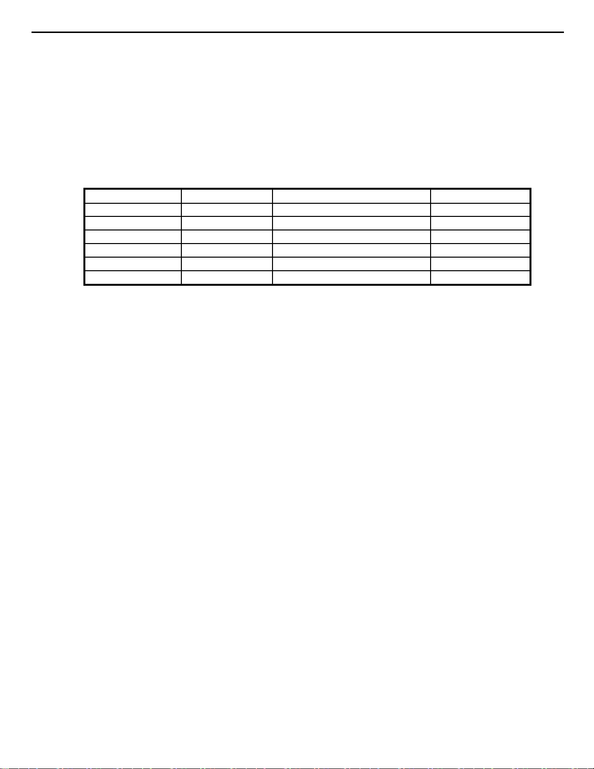
AVR8000 DC OFFSET ADJUSTMENT
Function : 6CH DIRECT INPUT
Volume level:minimum
Test position:Speaker out terminal (between "+" and "-") speaker jack
No load
a. Turn Power ON
b. Align to 0
Channel Check point Adjustment Location Adjustment value
CENTER CH CTR SPEAKER VC901(3channel AMP) 0±10mV
FRONT L CH FL SPEAKER VL901(3channel AMP) 0±10mV
REAR L CH SL SPEAKER VSL901(3channel AMP) 0±10mV
FRONT R CH FR SPEAKER VF901(2channel AMP) 0±10mV
REAR R CH SR SPEAKER VSR901(2channel AMP) 0±10mV
±5mV
c. After 5 Min. Repeat at 0±20mV
AVR8000
harman/kardon
24
24

AVR8000
harman/kardon
25
AVR8000
harman/kardon
26
55229930MS
55335050
55577360
55230040MP
55204550NR
55204560NR
55142780NR
55233150NR
55191530
55178110XX
27

AVR 8000
harman/kardon
28
AVR8000
29
harman/kardon
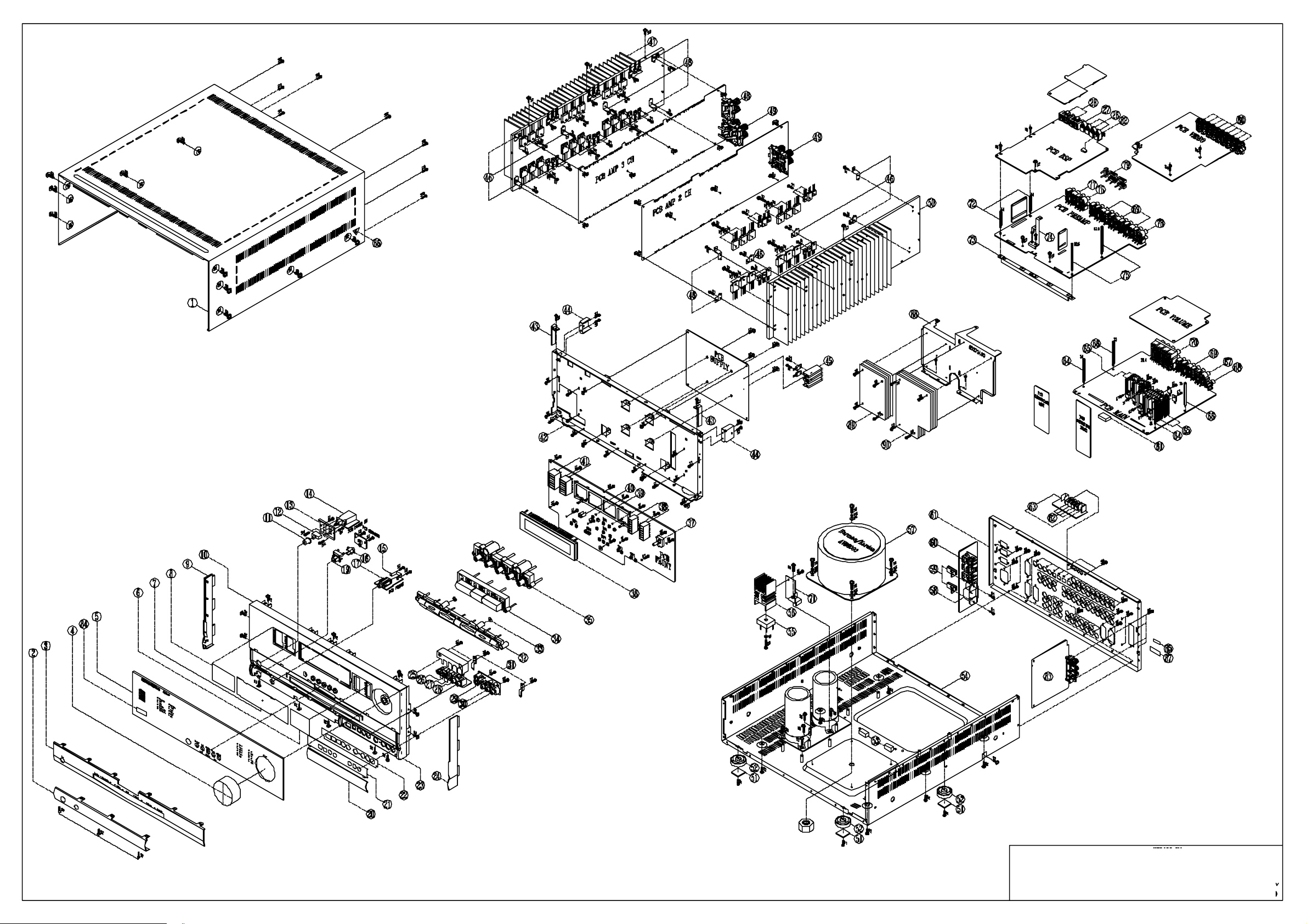
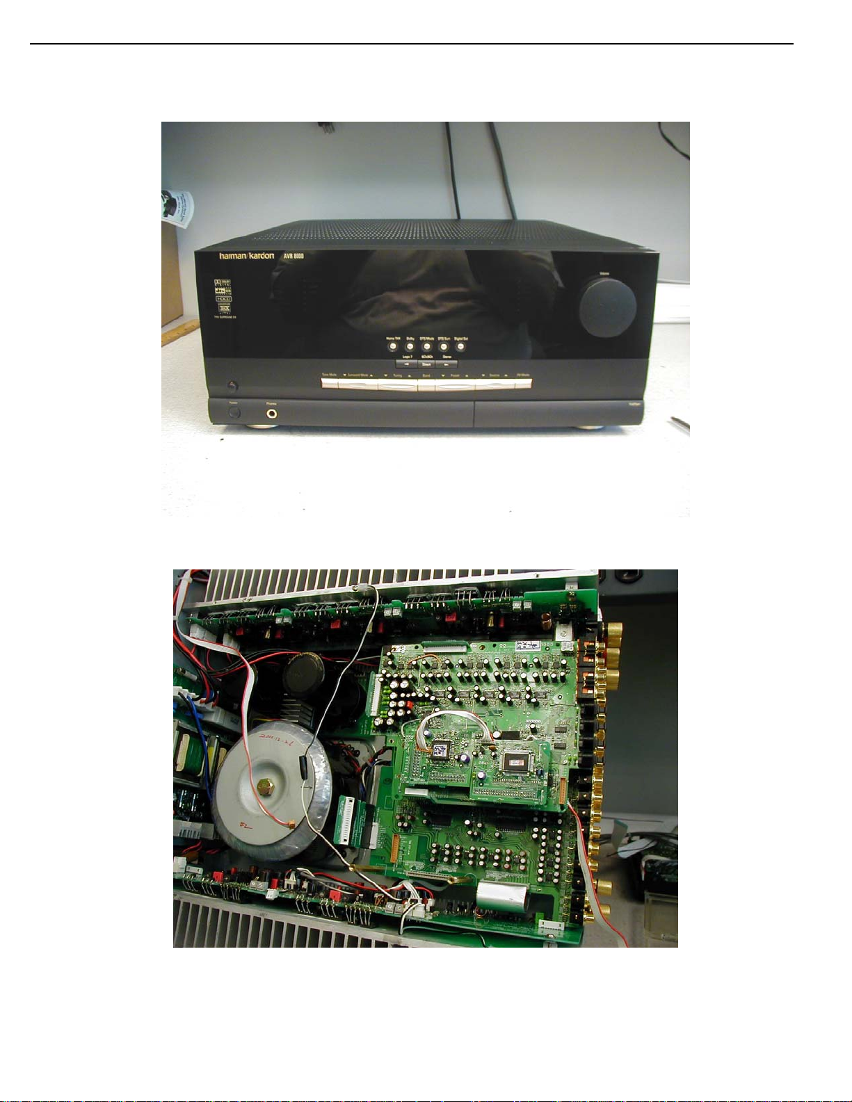
AVR 8000 DISASSEMBLY TIPS
Figure 1
Figure 2
View of the unit with the Top Cover and rear panel removed.
AVR8000
30
harman/kardon
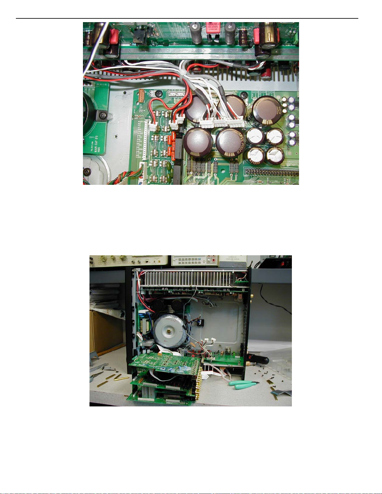
Figure 3
This view of the unit shows the connections from the 3-channel amp assembly to the main PC board (See
Figure 3). Note that 3 connections on Main PCB board are the same size, and use the same color
wires. These connections CAN BE INTERCHANGED if not careful and serious damage can occur if the
technician is not careful.
Figure 4
Be careful not to break any of the contacts, wires, or sub assemblies. The PC boards shown in the above
picture (Figure 4) are all interconnected through four separate extender boards. If you look carefully at the
stacked PC boards, you will notice that when they are not in the chassis with the rear plate attached, they are
NOT supported at one end. This may cause a Short to occur if one PC board touches another while the unit is
being serviced.
 Loading...