

Page 1

AVR 1710S, AVR 171S, AVR 171S/230C
AVR 1610S, AVR 161S, AVR 161S/230C
Audio/video receiver
ENGLISH
®
Owner’s Manual
TR00306_AVR_OM_161S and 171S_EMEA_B.indb 1 26/05/15 2:29 pm
Page 2

AVR
Table of Contents
INTRODUCTION 3
SUPPLIED ACCESSORIES 3
IMPORTANT SAFETY INFORMATION 3
PLACE THE AVR 3
FRONT-PANEL CONTROLS 4
REAR-PANEL CONNECTORS 6
SYSTEM REMOTE CONTROL FUNCTIONS 8
INTRODUCTION TO HOME THEATER 10
TYPICAL HOME THEATER SYSTEM 10
MULTICHANNEL AUDIO 10
SURROUND MODES 10
PLACE YOUR SPEAKERS 11
PLACING THE LEFT, CENTER AND RIGHT SPEAKERS 11
PLACING THE SURROUND SPEAKERS IN A 5.1-CHANNEL
SYSTEM 11
AVR 1710S/AVR 171S ONLY: PLACING THE SURROUND
SPEAKERS IN A 7.1-CHANNEL SYSTEM 11
AVR 1710S/AVR 171S ONLY: PLACING FRONT HEIGHT
SPEAKERS IN A 7.1-CHANNEL SYSTEM 11
PLACING THE SUBWOOFER 11
TYPES OF HOME THEATER SYSTEM CONNECTIONS 12
SPEAKER CONNECTIONS 12
SUBWOOFER CONNECTIONS 12
SOURCE DEVICE CONNECTIONS 12
VIDEO CONNECTIONS 13
RADIO CONNECTIONS 13
NETWORK CONNECTOR 14
USB PORT 14
MAKING CONNECTIONS 14
CONNECT YOUR SPEAKERS 14
CONNECT YOUR SUBWOOFER 15
CONNECT YOUR TV OR VIDEO DISPLAY 15
CONNECT YOUR AUDIO AND VIDEO SOURCE DEVICES 16
USB AND IOS DEVICES 18
CONNECT TO YOUR HOME NETWORK 18
CONNECT THE RADIO ANTENNAS 18
INSTALL A MULTIZONE SYSTEM 19
CONNECT IR EQUIPMENT 20
CONNECT THE TRIGGER OUTPUT 20
CONNECT TO AC POWER 20
SET UP THE REMOTE CONTROL 21
INSTALL THE BATTERIES IN THE REMOTE CONTROL 21
PROGRAM THE REMOTE TO CONTROL YOUR SOURCE
DEVICES AND TV 21
SET UP THE AVR 22
TURN ON THE AVR 22
USING THE ON-SCREEN MENU SYSTEM 22
CONFIGURE THE AVR FOR YOUR SPEAKERS 22
SET UP YOUR SOURCES 23
SET UP THE NETWORK 24
OPERATING YOUR AVR 25
HARMAN REMOTE APP 25
CONTROLLING THE VOLUME 25
MUTING THE SOUND 25
LISTENING THROUGH HEADPHONES 25
SELECTING A SOURCE 25
SELECTING A SURROUND MODE 25
LISTENING TO FM AND AM RADIO 26
LISTENING TO MEDIA ON A USB DEVICE 26
LISTENING TO AN IPOD/IPHONE/IPA D DEVICE 27
LISTENING TO VTUNER (INTERNET RADIO) 28
LISTENING TO MEDIA VIA YOUR HOME NETWORK 28
PLAYI NG MEDIA FROM A ROKU STREAMING STICK 29
LISTENING TO MEDIA VIA SPOTIFY CONNECT 29
USING THIS DEVICE WITH SPOTIFY CONNECT 29
ADVANCED FUNCTIONS 29
AUDIO PROCESSING AND SURROUND SOUND 29
MANUAL SPEAKER SETUP 30
LISTENING IN ZONE 2 33
SYSTEM SETTINGS 34
SLEEP TIMER 34
PROCESSOR RESET 34
TROUBLESHOOTING 35
SPECIFICATIONS 36
APPENDIX 37
2
TR00306_AVR_OM_161S and 171S_EMEA_B.indb 2 26/05/15 2:29 pm
Page 3

AVR
ENGLISH
Introduction, Supplied Accessories,
Important Safety Information and Place the AVR
Introduction
Thank you for choosing this Harman Kardon product!
For more than fifty years, the Harman Kardon mission has been to share a passion for music
and entertainment, using leading-edge technology to achieve premium performance.
Sidney Harman and Bernard Kardon invented the receiver, a single component designed
to simplify home entertainment without compromising performance. Over the years,
Harman Kardon products have become easier to use, while offering more features and
sounding better than ever.
The AVR 1710S/AVR 171S 7.2-channel and AVR 1610S/AVR 161S 5.1-channel digital
audio/ video receivers (AVRs) continue this tradition with some of the most advanced
audio and video processing capabilities yet, and a wealth of listening and viewing options.
To obtain the maximum enjoyment from your new AVR, please read this manual and
refer back to it as you become more familiar with its features and their operation.
If you have any questions about this product, its installation or its operation, please
contact your Harman Kardon retailer or custom installer, or visit the Web site at
www.harmankardon.com.
Supplied Accessories
The following accessory items are supplied with your AVR. If any of these items are
missing, please contact your Harman Kardon dealer or Harman Kardon customer service
at www.harmankardon.com.
• System remote control
• EzSet/EQ™ microphone
• AM loop antenna
• FM wire antenna
• Two AAA batteries
• AC power cord (AVR 171S/AVR 161S only)
IMPORTANT SAFETY INFORMATION
Verify Line Voltage Before Use
The AVR 1710S and AVR 1610S have been designed for use with 120-volt alternating
current (AC). The AVR 171S and AVR 161S have been designed for use with 220 – 240-volt
AC. Connection to a line voltage other than that for which your receiver is intended can
create a safety and fire hazard and may damage the unit. If you have any questions
about the voltage requirements for your specific model, or about the line voltage in your
area, contact your selling dealer before plugging the unit into a wall outlet.
Do Not Use Extension Cords
To avoid safety hazards, use only the power cord supplied with your unit. We do not
recommend that extension cords be used with this product. As with all electrical devices,
do not run power cords under rugs or carpets, or place heavy objects on them. Damaged
power cords should be replaced immediately by an authorized service center with a cord
meeting factory specifications.
Handle the AC Power Cord Gently
When disconnecting the power cord from an AC outlet, always pull the plug; never
pull the cord. If you do not intend to use your AVR for any considerable length of time,
disconnect the plug from the AC outlet.
Do Not Open the Cabinet
There are no user-serviceable components inside this product. Opening the cabinet may
present a shock hazard, and any modification to the product will void your warranty.
If water or any metal object such as a paper clip, wire or staple accidentally falls inside
the unit, disconnect it from the AC power source immediately, and consult an authorized
service center.
CATV or Antenna Grounding (AVR 1710S/AVR 1610S)
If an outside antenna or cable system is connected to this product, be certain that it is
grounded so as to provide some protection against voltage surges and static charges.
Section 810 of the United States National Electrical Code, ANSI/NFPA No. 70-1984,
provides information with respect to proper grounding of the mast and supporting
structure, grounding of the lead-in wire to an antenna discharge unit, size of grounding
conductors, location of antenna discharge unit, connection to grounding electrodes and
requirements of the grounding electrode.
NOTE TO CATV SYSTEM INSTALLER: This reminder is provided to call the CATV (cable TV)
system installer’s attention to article 820-40 of the NEC, which provides guidelines for
proper grounding and, in particular, specifies that the cable ground shall be connected
to the grounding system of the building, as close to the point of cable entry as possible.
Place the AVR
• Place the AVR on a firm and level surface. Be certain that the surface and any
mounting hardware can support the AVR’s weight.
• Provide proper space above and below the AVR for ventilation. Recommended
clearance distances are 30cm above the unit, 30cm behind the unit and 30cm on
each side of the unit.
• If you install the AVR in a cabinet or other enclosed area, provide cooling air within
the cabinet. Under some circumstances, a fan may be required.
• Do not obstruct the ventilation slots on the top of the AVR or place objects directly
over them.
• Do not place the AVR directly on a carpeted surface.
• Do not place the AVR in moist or humid locations, in extremely hot or cold locations,
in areas near heaters or heat registers, or in direct sunlight.
3
TR00306_AVR_OM_161S and 171S_EMEA_B.indb 3 26/05/15 2:29 pm
Page 4
AVR
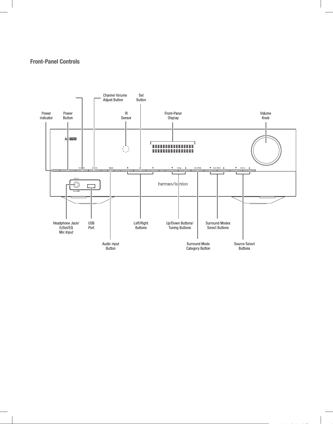
Front-Panel Controls
Tuning Mode Button (AVR
1710S/AVR 1610S)
RDS Button (AVR 171S/
Front-Panel Controls
AVR 161S)
4
TR00306_AVR_OM_161S and 171S_EMEA_B.indb 4 26/05/15 2:29 pm
Page 5

AVR
ENGLISH
Front-Panel Controls
Front-Panel Controls, continued
Power indicator/Power button: The AVR has three different power modes:
• Off (Power indicator glows solid amber): The Off mode minimizes energy consumption
when you’re not using the AVR. When the AVR is off, it will not automatically turn on
or play audio in response to an AirPlay stream from a networked device (AVR 1710S/
AVR 171S only). When the AVR is off, pressing the Power button turns it on. To turn
the AVR off when it is on, press the Power button for more than three seconds. The
Front-Panel Display will indicate “Your device is switched off” for two seconds, then
will switch off.
NOTE: You can use the System Setup menu to set the AVR to automatically enter
the off mode after it has been in the Sleep mode for a certain period of time. See
System Settings, on page 34.
• Sleep (Power indicator glows solid amber and front-panel display indicates “Device
sleep”): The Sleep mode powers-down some of the AVR’s circuitry, but allows the
AVR to automatically turn on and play audio in response to an AirPlay or DLNA DMR
stream from a networked device (AVR 1710S/AVR 171S only). When the AVR is in
Sleep, pressing the Power button turns it on. To put the AVR into Sleep when it is
on, press the Power button for less than three seconds. The front-panel display will
indicate “Device sleep” while the AVR is in the Sleep mode.
NOTE: The AVR will automatically enter the Sleep mode after 30 minutes of no audio
signal or user control input , unless USB, iPod, Home Network, vTuner, AirPlay, or
DLNA DMR is active. In these cases, the AVR will automatically enter the Sleep mode
after the number of hours set in the Auto Power Off system setting. See System
Settings, on page 34.
• On (Power indicator glows solid white): When the AVR is on it is fully operational.
Headphone jack/EzSet/EQ Mic input: Connect a 1/4” stereo headphone plug to this
jack for private listening. This jack is also used to connect the supplied microphone for
the EzSet/EQ setup procedure described in Configure the AVR For Your Speakers, on
page 22.
Tuning Mode button (AVR 1710S/AVR 1610S only): Press this button to toggle the radio
between the manual (one frequency step at a time) and automatic (seeks frequencies
with acceptable signal strength) FM tuning mode. The button also toggles the radio
between stereo and mono modes when an FM station is tuned in.
RDS button (AVR 171S/AVR 161S only): When listening to an FM radio station that
broadcasts RDS information, this button activates the various RDS functions.
USB port: The USB port can be used to play audio files from an Apple iOS
connected to the port, and can also be used to play MP3 and WMA audio files from a USB
device inserted into the port. Insert the connector or device into the USB port oriented so
it fits all the way into the port. You may insert or remove the connector or device at any
time – there is no installation or ejection procedure.
You can also use the USB port to perform firmware upgrades. If an upgrade for the AVR’s
operating system is released in the future, you will be able to download it to the AVR
using this port. Complete instructions will be provided at that time.
IMPORTANT: Do not connect a PC or other USB host/controller to this port, or you
may damage both the AVR and the other device.
Channel Volume Adjust button: Press this button to activate the individual channel
level adjustment. After pressing this button, use the Up/Down buttons/Tuning buttons to
select the channel for adjustment and use theLeft/Right buttons to adjust the channel’s
level.
Audio Input button: Press this button to change the audio input connection for the current
source. Use the Left/Right buttons to cycle through the available input connections, and
press the Set button to assign the currently-displayed connection to the source.
IR sensor: This sensor receives infrared (IR) commands from the remote control. Make
sure that the sensor is not blocked.
Set button: Press this button to select the currently highlighted menu item.
Left/Right buttons: Use these buttons to navigate the AVR’s menus.
®
device
Front-panel display: Various messages appear on this two-line display in response to
commands and changes in the incoming signal. In normal operation, the current source
name appears on the upper line, while the active surround mode is displayed on the
lower line. When the on-screen display menu system (OSD) is in use, the current menu
settings appear.
Up/Down buttons/Tuning buttons: Use these buttons to navigate the AVR’s menus.
When the radio is the active source, use these buttons to tune stations according to the
setting of the Tuning Mode button (see above).
Surround Mode Category button: Press this button to select a surround-sound
category. Each press changes the surround-mode category: Auto Select, Virtual, Stereo,
HARMAN NSP, Movie, Music and Video Game. To change the specific surround-sound
mode within the category, use the Surround Mode Select buttons. See Audio Processing
and Surround Sound, on page 29, for more information about surround modes.
Surround Mode Select buttons: After you have selected the desired surround-mode
category, press these buttons to select a specific mode within the category, such as to
change from Dolby
mode availability depends on the nature of the source input signal, i.e., digital versus
analog, and the number of channels encoded within the signal.
Source Select buttons: Press these buttons to select the active source.
Volume knob: Turn this knob to raise or lower the volume.
®
Pro Logic® II Movie mode to DTS® NEO:6 Cinema mode. Surround
5
TR00306_AVR_OM_161S and 171S_EMEA_B.indb 5 26/05/15 2:29 pm
Page 6
AVR
Rear-Panel Connectors
Digital Audio
A
Connectors
AVR 1710S/AVR 171S
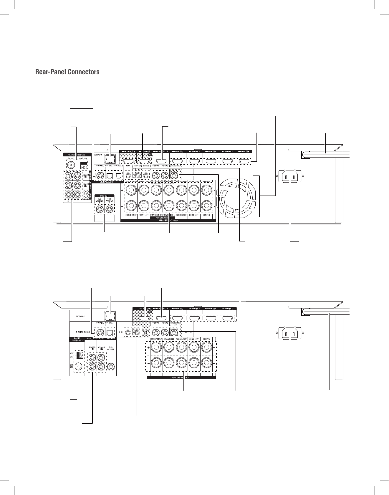
Rear-Panel Connectors
Connectors
Radio Antenna
Connectors
nalog Audio
Connectors
AVR 1610S/AVR 161S
Network
Connector
Subwoofer
Pre-Out
Connectors
HDMI Output
Connectors
HDMI/MHL Input
Connector
Speaker
Connectors
Analog Video
Connectors
Fan Vents
HDMI Input
Connectors
IR and Trigger
Connectors
Power Cord
(AVR 1710S)
AC Input
Connector (AVR 171S)
Digital Audio
Connectors
Radio Antenna
Connectors
Analog Audio
Network
Connector
Subwoofer
Pre-Out
Connector
HDMI Output
Connector
IR and Trigger
Connectors
HDMI/MHL Input
Connector
Speaker
Connectors
HDMI Input
Connectors
Analog Video
Connectors
AC Input
Connector
(AVR 161S)
Power Cord
(AVR 1610S)
6
TR00306_AVR_OM_161S and 171S_EMEA_B.indb 6 26/05/15 2:29 pm
Page 7
AVR
ENGLISH
Rear-Panel Connectors, continued
Digital Audio connectors: If your non-HDMI source devices have digital outputs,
connect them to the AVR’s digital audio connectors. NOTE: Make only one type of digital
connection (HDMI, optical or coaxial) from each device. See Connect Your Audio and Video
Source Devices, on page 16, for more information.
Radio Antenna connectors: Connect the supplied AM and FM antennas to their
respective terminals for radio reception.
Analog Audio connectors: The following analog audio connectors are provided:
• Analog Audio Input connectors: Use the AVR’s Analog Audio Input connectors for
source devices that don’t have HDMI or digital audio connectors. See Connect Your
Audio and Video Source Devices, on page 16, for more information.
• Zone 2 Out connectors (AVR 1710S/AVR 171S only): Connect these jacks to an
external amplifier to power the speakers in the remote zone of a multizone system.
Network connector: If your home network is wired, use a Cat. 5 or Cat. 5E Ethernet
cable (not supplied) to connect the AVR’s Network connector to your home network to
enjoy Internet radio and content from DLNA-compatible devices that are connected to the
network. See Connect to Your Home Network, on page 18, for more information.
Subwoofer Pre-Out connector: Connect this jack to a powered subwoofer with a linelevel input. See Connect Your Subwoofer, on page 15, for more information. NOTE: The
AVR 1710S and AVR 171S have two subwoofer connectors.
HDMI Output connectors: If your TV has an HDMI connector and you are connecting
HDMI source devices to the AVR, use an HDMI cable (not included) to connect it to the
AVR’s HDMI Out connector. NOTE: The AVR 1710S and AVR 171S have two HDMI Out
connectors.
Notes on using the HDMI Output connector:
• When connecting a DVI-equipped display to the HDMI Out connector, use an
HDMI-to-DVI adapter and make a separate audio connection.
• Make sure the HDMI-equipped display is HDCP (High-bandwidth Digital Content
Protection)-compliant. If it isn’t, do not connect it via an HDMI connection; use an
analog video connection instead and make a separate audio connection.
• AVR 1710S/AVR 171S only: If you have connected a 3D-capable TV to HDMI
Out 1 and a 2D-capable TV to HDMI Out 2, the AVR will not allow 3D playback
when both TVs are powered on. To watch 3D content, turn off the AVR and both
TVs, then first turn on the 3D TV, then turn on the AVR, and finally turn on the 3D
source device. Do NOT turn the 2D TV back on.
Rear-Panel Connectors
®
HDMI
Input connectors: An HDMI connection transmits digital audio and video signals
between devices. If your source devices have HDMI connectors, using them will provide
the best possible video and audio performance quality. Since the HDMI cable carries
both digital video and digital audio signals, you do not have to make any additional audio
connections for devices you connect via the HDMI connection. See Connect Your Audio
and Video Source Devices, on page 16, for more information.
IR and Trigger connector: The following IR and trigger connectors are provided:
• IR In connectors: When the IR sensor on the front panel is blocked (such as when
the AVR is installed inside a cabinet), connect an optional IR receiver to the IR In
jack.
• 12V Trigger connector: This connector provides 12V DC whenever the AVR is on. It
can be used to turn on and off other devices such as a powered subwoofer.
• Zone 2 IR Input connector (AVR 1710S/AVR 171S only): Connect a remote IR
receiver located in Zone 2 of a multizone system to this jack to control the AVR from
the remote zone.
Fan Vents (AVR 1710S/AVR 171S only): These vents are used by the AVR’s fan to
cool the system. Maintain a clearance of at least three inches (75mm) from the nearest
surface to avoid overheating the unit. It is normal for the fan to remain off at most normal
volume levels. An automatic temperature sensor turns the fan on only when it is needed.
IMPORTANT NOTE: Never block the fan vents. Doing so could allow the AVR
to overheat to dangerous levels.
AC Input connector (AVR 171S/AVR 161S only): After you have made and verified
all other connections, plug the supplied AC power cord into this receptacle and into an
unswitched wall outlet.
Power cord (AVR 1710S/AVR 1610S only): After you have made and verified all other
connections, plug the power cord into an unswitched wall outlet.
HDMI/MHL Input connector: If you have a Roku Streaming Stick or other MHL-capable
device, connect it only to this HDMI/MHL In connector. If you do not have an MHL device
you can use this connector for an HDMI-capable device.
Speaker connectors: Use two-conductor speaker wire to connect each set of terminals
to the correct speaker. See Connect Your Speakers, on page 14, for more information.
NOTE:
The Assigned Amp speaker connectors (AVR 1710S/AVR 171S only) are used
for the surround back or Front Height channels in a 7.1- channel home theater, or
you can reassign them to a remote room for multizone operation or to front height
channels for Dolby® Pro Logic IIz operation. See Place Your Speakers, on page 11,
for more information.
Analog Video connectors: The following Analog Video connectors are provided:
• Composite Video Input connectors: Use composite video connectors for video
source devices that don’t have HDMI connectors. You will also need to make an
audio connection from the source device to the AVR. See Connect Your Audio and
Video Source Devices, on page 16, for more information.
• Composite Video Monitor Out connector: If your TV or video display does not
have an HDMI connector, or if your TV does have an HDMI connector but you are
connecting some source devices with only composite video connectors, use a
composite video cable (not included) to connect the AVR’s Composite Video Monitor
Out connector to your TV ’s composite video input.
7
TR00306_AVR_OM_161S and 171S_EMEA_B.indb 7 26/05/15 2:29 pm
Page 8
AVR
System Remote Control Functions
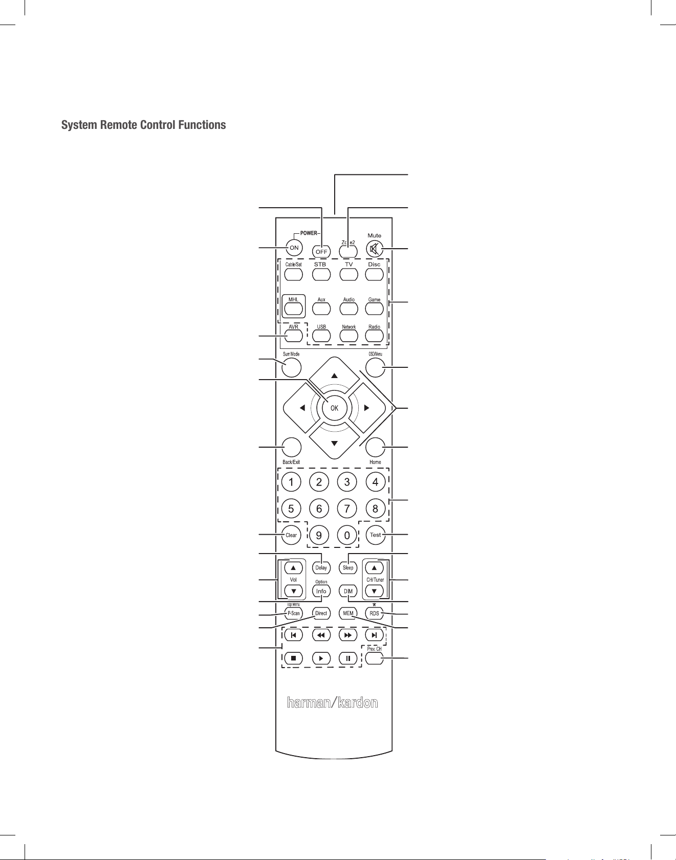
System Remote Control Functions
IR Transmitter
Power Off Button
Power On Button
AVR Button
Surround Modes Button
OK Button
Back/Exit Button
Zone 2 Button
(A
VR 1710S/AVR 171S only)
Mute Button
Source Selector Buttons
OSD/Menu Button
Up/Down/Left/Right
Buttons
Home Button
Number Buttons
Clear Button
Delay Button
Volume Up/Down Buttons
Info/Option Button
Preset Scan Button
Direct Button
Transport Control Buttons
8
Test Tone Button
Sleep Button
Channel/Tuner Buttons
Display Dimmer Button
RDS Button
Memory Button
Previous Channel Button
TR00306_AVR_OM_161S and 171S_EMEA_B.indb 8 26/05/15 2:29 pm
Page 9

AVR
ENGLISH
System Remote Control Functions
System Remote Control Functions, continued
In addition to controlling the AVR, the AVR remote is capable of controlling eight other
devices, including an iPod/iPhone device connected to the AVR’s front-panel USB port.
During the installation process, you may program the codes for each of your source
components into the remote. (See Program the Remote to Control Your Source Devices
and TV, on page 21, for programming information.) To operate a component, press its
Source Selector button to change the remote’s control mode.
A button’s function depends on which component is being controlled. See Table A13 in
the Appendix for listings of the functions for each type of component. Most of the buttons
on the remote have dedicated functions, although the precise codes transmitted vary
depending on the specific device being controlled. Due to the wide variety of functions for
various source devices, we have included only a few of the most-often used functions on
the remote: number buttons, transport controls, television-channel control, menu access
and power on and off. Buttons dedicated to the AVR – AVR Power On/Off, Surround
Modes, Volume, Mute, Delay and Sleep Settings – are available at any time, even when
the remote is controlling another device.
Power On/Power Off buttons: Press these buttons to turn the AVR on and put it into
Sleep or turn it off. See Power Indicator/Power Button, on page 4, for more information.
IR Transmitter: As buttons are pressed on the remote, infrared codes are emitted
through this lens.
Zone 2 button (AVR 1710S/AVR 171S only): Use this button to select whether the AVR
commands will affect the main listening area (Zone 1) or the remote zone of a multizone
system (Zone 2). When the remote is in the Zone 2 control mode, the Zone 2 button will
illuminate whenever you press a button.
Mute button: Press this button to mute the AVR’s speaker-output connectors and
headphone jack. To restore the sound, press this button or adjust the volume.
Source Selector buttons: Press one of these buttons to select a source device, e.g.,
Disc, Cable/Sat, Radio, etc. This action will also turn on the AVR and switch the remote’s
control mode to operate the selected source device.
• The first press of the Radio button switches the AVR to the last-used tuner band (AM
or FM). Each successive press changes the band.
• The first press of the USB button switches the AVR to the last-used source (USB or
iPod). Each successive press cycles between the two sources.
• The first press of the Network button switches the AVR to the last-used source
(Network or vTuner). Each successive press cycles between the two sources.
AVR button: Press to put the remote into the AVR control mode.
Surround Modes button: Press this button to access the Surround Modes submenu.
Select a surround-mode category: Auto Select, Virtual Surround, Stereo, HARMAN NSP,
Movie, Music or Game. When you select the category, it is highlighted and the surround
mode changes.
To change the surround mode for the selected category navigate to the Surround Mode
menu in the AVR’s on-screen display menu, select the desired category, and use the Left/
Right buttons to select one of the available surround modes. See the Advanced Functions
section, on page 29, for more information.
OSD/Menu button: When the remote is controlling the AVR, press this button to display
the AVR’s on-screen display (OSD) menu. This button is also used within the tuner menus
and an iPod connected to the AVR’s front-panel USB port, and is also used to display the
main menu on some source devices.
Up/Down/Left/Right buttons: These buttons are used to navigate the menu system and
to operate the tuner.
OK button: This button is used to select items from the menu system.
Back/Exit button: Press this button to return to the previous menu or to exit the menu
system.
Home button: Press this button to display the Home menu for a Roku Streaming Stick
that is connected to the AVR’s MHL/HDMI connector.
Number buttons: Use these buttons to enter numbers for radio-station frequencies or
to select station presets.
™
Clear button: Press this button to clear a radio station frequency you have started to
enter.
Test Tone button: Press this button to activate test noise that will circulate through each
speaker, allowing you to adjust the individual speaker levels. Use the Up/Down buttons
to switch the noise to a different speaker and use the Left/Right buttons to change the
volume of the speaker the noise is playing through.
Delay Adjust button: Pressing this button lets you adjust two different types of delay
settings (use the Up/Down buttons to cycle through the settings):
• Lip Sync: This setting lets you resynchronize the audio and video signals from a
source to eliminate a “lip sync” problem. Lip-sync issues can occur when the video
portion of a signal undergoes additional processing in either the source device or the
video display. Use the Left/Right buttons to delay the audio by up to 180ms.
• Distance: These settings let you set the delay for each speaker to compensate for the
different distances they may be from the listening position. Use the Up/Down buttons
to cycle through each of the system’s speakers, and use the Left/Right buttons to set
the distance each speaker is from the listening position. See Manual Speaker Setup,
on page 30, for more information.
Sleep button: Press this button to activate the sleep timer, which turns off the receiver
after a programmed period of time. Each press increases the time by 10 minutes, up to
90 minutes – ending with the “Sleep Off” message.
Volume Up/Down buttons: Press these buttons to raise or lower the volume.
Channel/Tuner buttons: When radio has been selected, press these buttons to select a
preset radio station. While operating a cable, satellite or HDTV set-top box or a television,
press these buttons to change channels.
Info/Option button: Press to display the available option settings for the current
source.
Display Dimmer button: Press this button to dim the AVR’s front-panel Message Display
partially or fully.
Preset Scan button: When Radio is the selected source, press this button to play each of
your preset radio stations in order for five seconds. Pressing the button again to remain
tuned to the current station.
RDS button (AVR 171S/AVR 161S only): When listening to an FM radio station that
broadcasts RDS information, this button activates the various RDS functions.
Direct button: Press this button to directly tune to a radio station by using the Number
buttons to enter its frequency.
Memory button: Press this button to save the current radio or vTuner station as a
preset.
Transport Control buttons: These buttons are used to control source devices.
Previous Channel button: When TV is the selected source, press this button to switch
to the previously-tuned channel.
9
9
TR00306_AVR_OM_161S and 171S_EMEA_B.indb 9 26/05/15 2:29 pm
Page 10

AVR
Introduction to Home Theater
Introduction to Home Theater
This introductory section will help you to familiarize yourself with some basic concepts
unique to multichannel surround-sound receivers, which will make it easier for you to
set up and operate your AVR.
Typical Home Theater System
A home theater typically includes an audio/video receiver, which controls the system
and supplies amplification for the loudspeakers; a disc player; a source component for
television broadcasts (cable box, satellite dish receiver, HDTV tuner or antenna connected
to the TV); a TV or video display; and multiple loudspeakers.
Multichannel Audio
The main benefit of a home theater system is its ability to produce “surround sound.”
Surround sound uses multiple speakers and amplifier channels to immerse you in the
audio/video presentation for a dramatically increased sense of realism.
Your AVR may have up to seven main speakers connected directly to it, plus a subwoofer.
Each main speaker is powered by its own amplifier channel inside the AVR. A system
with more than two speakers is called a multichannel system. The different main speaker
types in a home theater system are:
Front Left and Right: The front left and right speakers are used as in a two-channel
system. In many surround-sound modes, these speakers are secondary, while the main
action, especially dialogue, is reproduced by the center speaker.
Center: When you are watching movies and television programs, the center speaker
reproduces most of the dialogue and other soundtrack information, anchoring it with the
picture. When you are listening to a musical program, the center speaker helps to create
a seamless front soundstage, creating a realistic “you-are-there” listening experience.
Surround Left and Right: The surround left and right speakers produce ambient sounds
that help create a realistic and immersive surround-sound environment. They also help
recreate directional sound effects such as aircraft flyovers.
Many people expect the surround speakers to play as loudly as the front speakers.
Although you will calibrate all of the speakers in your system to sound equally loud at the
listening position, most artists use the surround speakers for ambient effects only, and
they create their programs to steer relatively little sound to these speakers.
Subwoofer: A subwoofer is designed to play only the lowest frequencies (the deep
bass). It augments smaller, limited-range main speakers that are usually used for the
other channels. Many digital-format programs, such as movies recorded in Dolby Digital,
contain a low-frequency effects (LFE) channel that is directed to the subwoofer. The LFE
channel packs the punch of a rumbling train or airplane, or the power of an explosion,
adding realism and excitement to your home theater. Some people use two subwoofers
for additional power and for even distribution of the sound.
Surround Back Left and Right (AVR 1710S/AVR 171S only): Surround back channel
speakers are used with surround modes such as the Dolby Digital EX, Dolby Digital Plus,
Dolby TrueHD, DTS-ES
Master Audio™ and Logic 7® 7.1 modes that are designed for 7.1-channel systems.
Front Height Left and Right (AVR 1710S/AVR 171S only): Your AVR includes Dolby Pro
Logic IIz decoding, which uses the AVR’s Assigned Amp channels as front height channels.
The addition of front height channels – an additional pair of speakers positioned above
the front left and right speakers – produces a surround-sound experience with added
depth and dimension by creating lifelike sound that comes at you from varying heights.
NOTE: You can set up your system to use either surround back speakers or front height
speakers; you cannot use both.
The surround back and front height channel speakers are optional. If your system does
not include surround back or front height speakers, you can set up your AVR with a
5.1-channel surround-sound system in the main listening area, and you can reassign
the surround back channel amplifiers to power loudspeakers located in another room
in a multizone system.
®
(Discrete and Matrix), DTS-HD™ High Resolution Audio, DTS-HD
Surround Modes
There are different theories as to the best way to present surround sound and to
distribute each audio channel’s sounds to the surround-sound system’s speakers.
A variety of algorithms have been developed in an effort to recreate the way we hear
sounds in the real world, providing you with a rich variety of options. Several companies
have developed different surround-sound technologies, all of which can be accurately
reproduced by your AVR:
• Dolby Laboratories: Dolby TrueHD, Dolby Digital Plus, Dolby Digital, Dolby Digital
EX (AVR 170S/AVR 171S only), Dolby Pro Logic
170S/AVR 171S only).
• DTS: DTS-HD High Resolution Audio, DTS-HD Master Audio, DTS, DTS-ES (Discrete
and Matrix), DTS Neo:6
• HARMAN International: HARMAN NSP, HARMAN Headphone.
• Stereo Modes: Generic modes that expand upon conventional two-channel stereo,
including 5CH Stereo and 7CH Stereo (AVR 1710S/AVR 171S only).
Appendix Table A10, on page 41, contains detailed explanations of the different
surround-sound options available on your AVR. Digital surround-sound modes, such as
the Dolby Digital and DTS modes, are available only on specially encoded programs,
such as those available via HDTV, DVD and Blu-ray Disc media and digital cable or
satellite television. Other surround modes may be used with digital and analog signals
to create a different surround presentation or to use a different number of speakers.
Surround-mode selection depends upon the number of speakers in your system, the
program you are watching or listening to, and your personal tastes.
®
, DTS 96/24™.
®
II, Dolby Pro Logic® IIx and IIz (AVR
10
TR00306_AVR_OM_161S and 171S_EMEA_B.indb 10 26/05/15 2:29 pm
Page 11
AVR
ENGLISH
TV
(
)
Place Your Speakers
Place Your Speakers
Determine the locations for your system’s speakers according to their manufacturer’s
directions and the layout of your listening room. Use the illustrations below as a guide for
7.1-channel systems (AVR 1710S/AVR 171S only) and 5.1-channel systems.
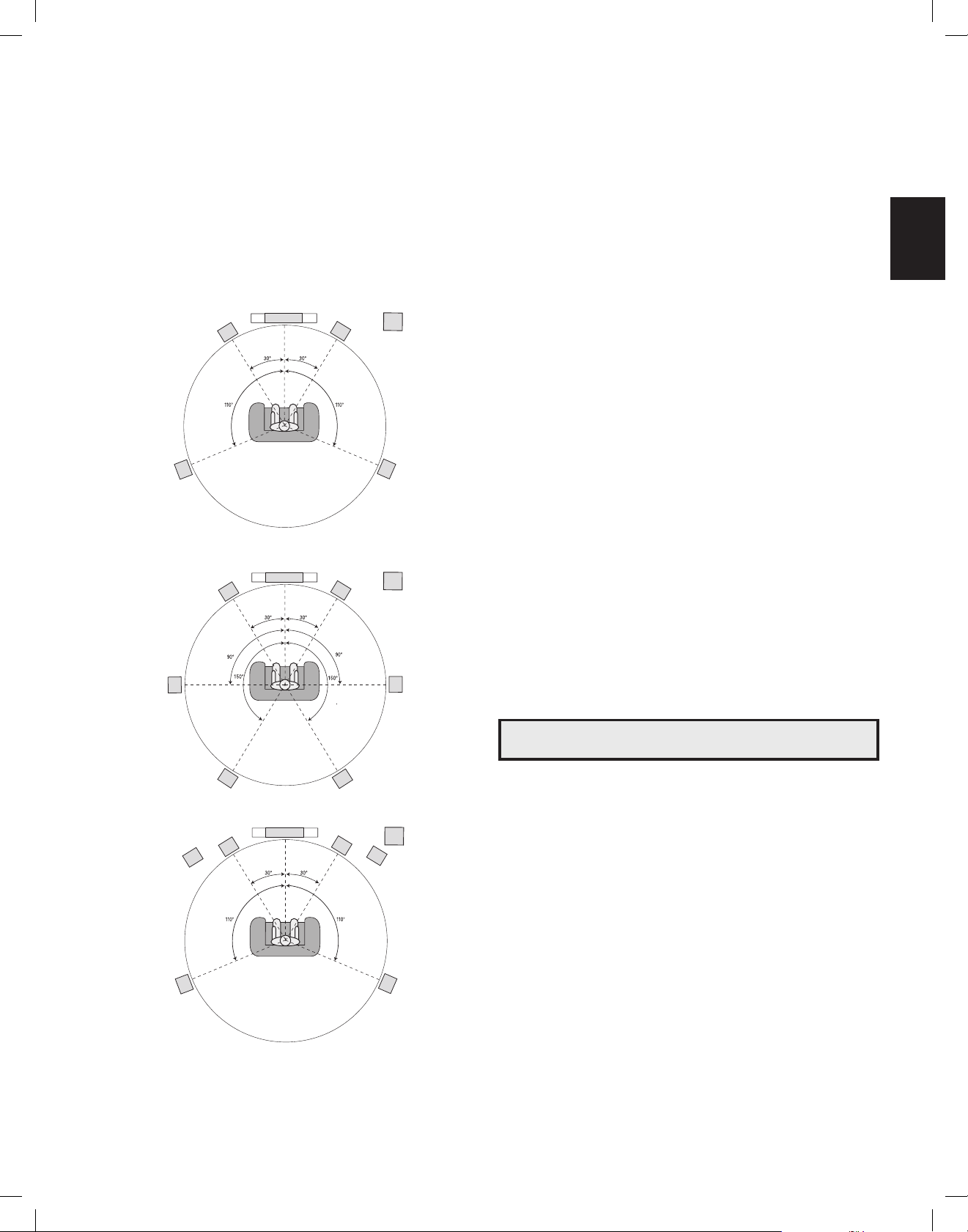
To create the most realistic surround-sound environment possible, you should place
your speakers in a circle with the listening position at its center. You should angle each
speaker so it directly faces the listening position. Use the diagrams below as a guide.
C
FL
SL
Speaker Positioning for 5.1-Channel Systems
TV
C
FL
SUB
FR
SR
SUB
FR
SRSL
NOTE: In a 7.1-channel system, you must choose to use either surround back speakers
or front height speakers – you cannot use both simultaneously.
Placing the Left, Center and Right Speakers
Place the center speaker either on top of, below or mounted on the wall above or below
the TV or video display screen. Place the front left and right speakers along the circle,
about 30 degrees from the center speaker and angled toward the listener.
Place the front left, front right and center speakers at the same height, preferably at
about the same height as the listener’s ears. The center speaker should be no more than
2 feet (0.6m) above or below the left/right speakers. If you’re using only two speakers
with your AVR, place them in the front left and right positions.
Placing the Surround Speakers in a 5.1-Channel System
You should place the left and right surround speakers approximately 110 degrees from
the center speaker, slightly behind and angled toward the listener. Alternatively, place
them behind the listener, with each surround speaker facing the opposite-side front
speaker. You should place the surround speakers 2 feet – 6 feet (0.6m – 1.8m) higher
than the listener’s ears.
AVR 1710S/AVR 171S only: Placing the Surround Speakers in a
7.1- Channel System
In a 7.1-channel system, place the side surround speakers 90 degrees from the center
speaker, directly to either side of the listening position. Place the surround back left and
right speakers 150 degrees from the center speaker, directly facing the opposite-side
front speaker. You should place all the surround speakers 2 feet – 6 feet (0.6m – 1.8m)
higher than the listener’s ears.
AVR 1710S/AVR 171S only: Placing Front Height Speakers in a 7.1Channel System
Your AVR includes Dolby Pro Logic IIz decoding, which uses the AVR’s Assigned Amp
channels as front height channels. The addition of front height channels – an additional
pair of speakers positioned above the front left and right speakers – produces a surroundsound experience with added depth and dimension by creating lifelike sound that comes
at you from varying heights.
We recommend placing front height speakers at least 3 feet (0.9m) higher than the front
left and front right speakers, and directly above or farther apart than the front left and
right speakers. The higher and further apart you place the front height speakers, the more
you should angle them down and in toward the listening position.
SBL
TV
C
FHL* FHR*
Speaker Positioning for 7.1-Channel Systems (A
Middle: with Surround Back Speakers; Bottom: with Front Height Speakers
FL
* FHL and FHR speakers should be at least
3 ft (0.9m) above the FL and FR speakers.
SBR
SUB
FR
SRSL
VR 1710S/AVR 171S only)
NOTE: Your receiver will sound its best when the same model or brand of loudspeaker
is used for all positions.
Placing the Subwoofer
Because a room’s shape and volume can have a dramatic effect on a subwoofer’s
performance, it is best to experiment with placement so that you will find the location
that produces the best results in your particular listening room. With that in mind, these
rules will help you get started:
• Placing the subwoofer next to a wall generally will increase the amount of bass in
the room.
• Placing the subwoofer in a corner generally will maximize the amount of bass in
the room.
• In many rooms, placing the subwoofer along the same plane as the left and right
speakers can produce the best integration between the sound of the subwoofer and
that of the left and right speakers.
• In some rooms, the best performance could even result from placing the subwoofer
behind the listening position.
A good way to determine the best location for the subwoofer is by temporarily placing it in
the listening position and playing music with strong bass content. Move around to various
locations in the room while the system is playing (putting your ears where the subwoofer
would be placed), and listen until you find the location where the bass performance is
best. Place the subwoofer in that location.
11
TR00306_AVR_OM_161S and 171S_EMEA_B.indb 11 26/05/15 2:29 pm
Page 12
AVR
Types of Home Theater System Connections
Types of Home Theater System Connections
There are different types of audio and video connections used to connect the AVR to your
speakers, your TV or video display, and your source devices. The Consumer Electronics
Association has established the CEA® color-coding standard.
Analog Audio Connection Color
Front Left/Right White/Red
Center Green
Surround Left/Right Blue/Gray
Surround Back/Front Height Left/Right Brown/Tan
Subwoofer Purple
Digital Audio Connection Color
Coaxial (input or output) Orange
Optical Input Black
Analog Video Connection Color
Composite Video Yellow
Speaker Connections
Speaker cables carry an amplified signal from the AVR’s speaker terminals to each
loudspeaker. They contain two wire conductors, or leads, that are differentiated in some
way, such as with colors or stripes.
The differentiation helps you maintain proper polarity, without which your system’s lowfrequency performance can suffer. Each speaker is connected to the AVR’s speakeroutput terminals using two wires, one positive (+) and one negative (–). Always connect
the positive terminal on the speaker, which is usually colored red, to the positive terminal
on the receiver, which is colored as indicated in the Connection Color Guide Table, above.
The negative terminals on the speakers and the AVR are black.
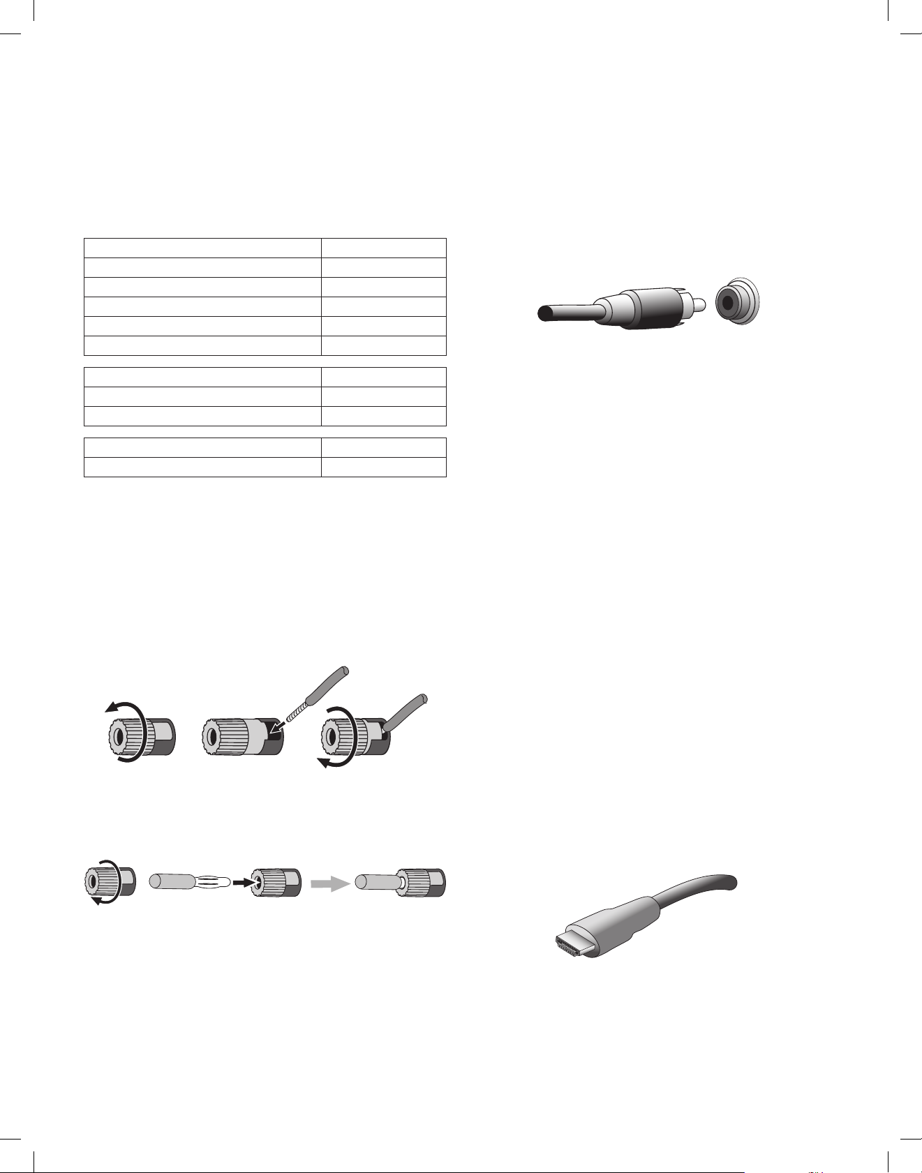
Your AVR uses binding-post speaker terminals that can accept bare-wire cables or
banana plugs. Bare-wire cables are installed as shown below:
1. Unscrew Cap 3. Tighten Cap2. Insert Bare Wire
Banana plugs are inserted into the hole in the middle of the terminal cap, as shown
below:
A. Tighten Cap
B. Insert Banana Connector into Hole in Cap
Subwoofer Connections
The subwoofer is a speaker dedicated to reproducing only the low (bass) frequencies,
which require more power. To obtain the best results, most speaker manufacturers offer
powered subwoofers that contain their own amplifiers. Use a single RCA audio cable to
make a line-level (non-amplified) connection from the AVR’s Subwoofer connector to a
corresponding input jack on the subwoofer. (The AVR 1710S and AVR 171S have two
subwoofer output connections.)
Although the AVR’s purple subwoofer output looks similar to a full-range analog audio
jack, it is filtered so that only the low frequencies pass through it. Don’t connect this
output to any device other than a subwoofer.
Source Device Connections
Audio and video signals originate in source devices (components where a playback
signal originates) such as your Blu-ray Disc or DVD player, CD player, DVR (digital video
recorder) or other recorder, tape deck, game console, cable or satellite television tuner,
an iPod or iPhone (connected to the AVR’s USB port) or an MP3 player. The AVR’s FM/AM
tuner also counts as a source, even though no external connections are needed other
than the FM and AM antennas. Separate connections are required for the audio and
video portions of the source device’s signal, except for digital HDMI connections. The
types of connections you use will depend upon the capabilities of the source device and
of your TV or video display.
Digital Audio Connections – HDMI
There are two types of audio connections – digital and analog. Digital audio signals are
required for listening to sources encoded with digital surround modes, such as Dolby
Digital and DTS, or for uncompressed PCM digital audio. Your AVR has three types of
digital audio connections: HDMI, coaxial and optical. Do not use more than one type of
digital audio connection for each source device. However, it’s okay to make both analog
and digital audio connections to the same source.
Your AVR is equipped with rear-panel HDMI input and output connectors. HDMI technology
enables high-definition digital audio and video information to be carried using a single
cable, delivering the highest quality picture and sound. If your TV or video display device
has an HDMI input connector, make a single HDMI connection from each HDMI-enabled
source device to the AVR. Usually, a separate digital audio connection is not required.
The AVR’s HDMI output connection contains an Audio Return Channel (ARC) that carries a
digital audio signal from your TV or video display back to the AVR. It allows you to listen
to HDMI devices that are connected directly to your TV (such as an Internet connection)
without making an additional connection from the device to the AVR. The ARC signal
is active when the TV source is selected. See System Settings, on page 34, for more
information. (The AVR 1710S and AVR 171S have two HDMI output connections. Only
HDMI Out 1 has ARC.)
The HDMI connector is shaped for easy plug-in (see illustration, below), and HDMI
cable runs are limited to about 10 feet (3m). If your video display has a DVI input and is
HDCP-compliant, use an HDMI-to-DVI adapter (not included), and make a separate audio
connection.
Always connect the colored (+) terminal on the AVR to the (+) terminal on the speaker
(usually red), and the black (–) terminal on the AVR to the (–) terminal on the speaker
(usually black).
IMPORTANT: Make sure the ( + ) and ( – ) bare wires do not touch each other or
the other terminal. Touching wires can cause a short circuit that can damage your
receiver or amplifier.
12
TR00306_AVR_OM_161S and 171S_EMEA_B.indb 12 26/05/15 2:29 pm
Page 13
AVR
ENGLISH
Types of Home Theater System Connections
Digital Audio Connections – Coaxial
Coaxial digital audio jacks are usually color-coded in orange. Although they look like
standard RCA-type analog jacks, you should not connect coaxial digital audio outputs to
analog inputs or vice versa.
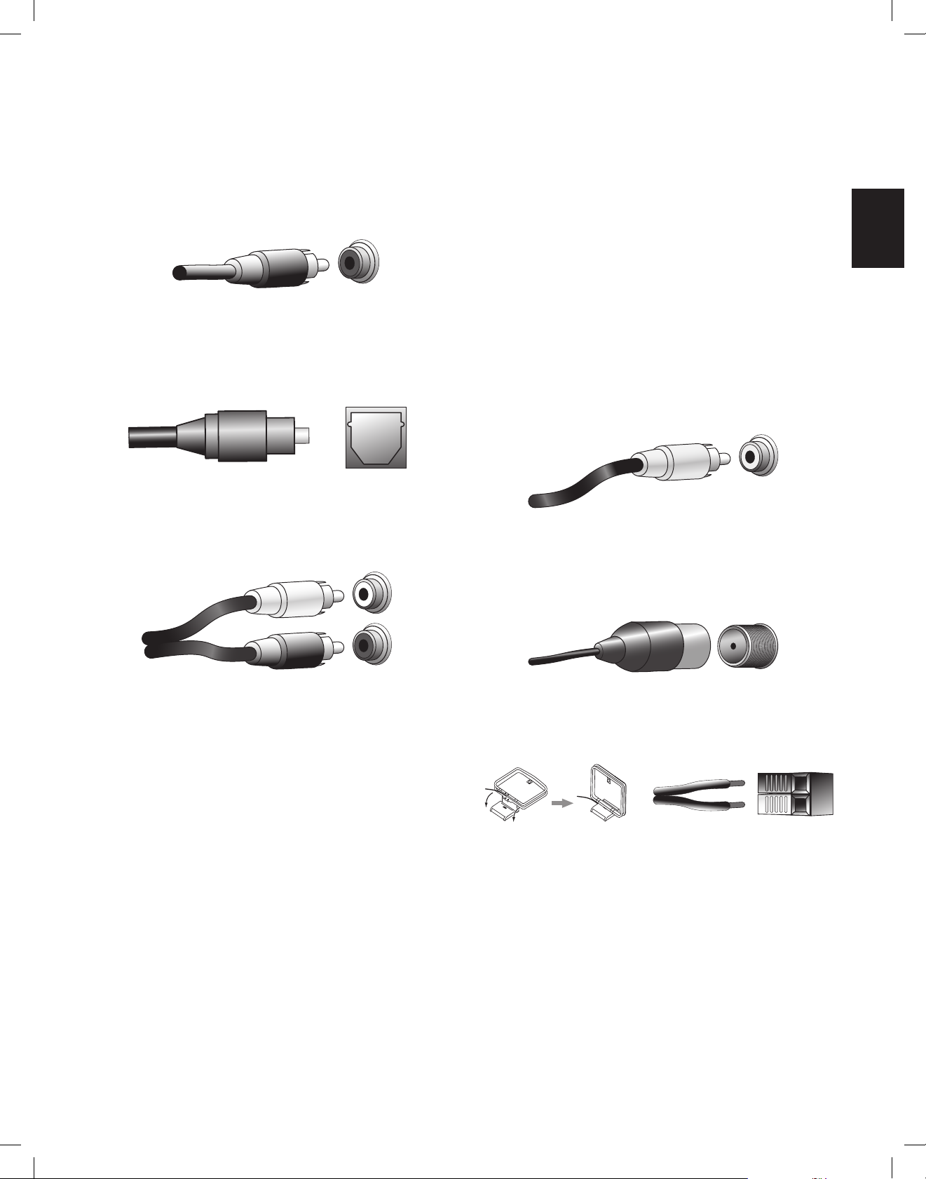
Digital Audio Connections – Optical
Optical digital audio connectors are normally covered by a shutter to protect them from
dust. The shutter opens as the cable is inserted. Optical input connectors are color-coded
using a black shutter.
Analog Audio Connections
Two-channel analog connections require a stereo audio cable, with one connector for
the left channel (white) and one for the right channel (red). These two connectors are
attached to each other.
Video Connections
Many source devices output both audio and video signals (e.g., Blu-ray Disc, DVD
player, cable television box, HDTV tuner, satellite box, VCR, DVR). In addition to an audio
connection as described above, make a video connection for each of these source
devices. Make only one type of video connection for each device.
Digital Video Connections
If you have already connected a source device to one of the AVR’s HDMI input connectors,
you have automatically made a video connection for that device, since the HDMI cable
carries both digital audio and digital video signals.
Analog Video Connections – Composite Video
Composite video is the most commonly available analog video connection. Both the
chrominance (color) and luminance (intensity) components of the video signal are
transmitted using a single cable. The jack is usually color-coded yellow and looks like an
analog audio jack. Do not connect a composite video jack to an analog audio or coaxial
digital audio jack, or vice versa.
Radio Connections
Your AVR uses separate terminals for the included FM and AM antennas. The FM antenna
uses a 75-ohm F-connector.
For source devices that have both digital and analog audio outputs, you may make both
connections. If you are going to be setting up a multizone system (AVR 1710S/AVR 171S
only), remember that Zone 2 is an audio-only zone (the AVR does not have a Zone 2 video
output). Therefore, make analog connections for any audio source devices (such as a CD
changer) that you will want available for listening in Zone 2 at all times.
The AM antenna connector uses spring-clip terminals. After assembling the antenna as
shown below, press the levers to open the connectors, insert the bare wires into the
openings, and release the levers to secure the wires. The antenna wires are not polarized,
so you can insert either wire into either connector.
13
TR00306_AVR_OM_161S and 171S_EMEA_B.indb 13 26/05/15 2:29 pm
Page 14
AVR
d
S
Types of Home Theater System Connections and
Making Connections
Network Connector
The AVR’s Network connector allows you to enjoy Internet radio or content from other
DLNA or Airplay-compatible devices that are connected to the same network. Use a Cat.
5 or Cat. 5E Ethernet cable to connect the AVR’s RJ-45 connector to your home network.
USB Port
The AVR can play audio files from an Apple iOS® device connected to the USB port,
and allows you to control the iOS device via the AVR remote control. The AVR can also
play MP3 and WMA audio files from a USB device inserted into the USB port. Insert the
connector or device into the USB port oriented so it fits all the way into the port. You may
insert or remove the connector or device at any time – there is no installation or ejection
procedure.
The USB port on your AVR is also used to perform firmware upgrades. If an upgrade for
the AVR’s operating system is released in the future, you will be able to download it to the
AVR using this port. Complete instructions will be provided at that time.
Making Connections
CAUTION: Before making any connections to the audio/video receiver, ensure
that the AVR’s AC cord is unplugged from the AC outlet. Making connections
with the receiver plugged in and turned on could damage the speakers.
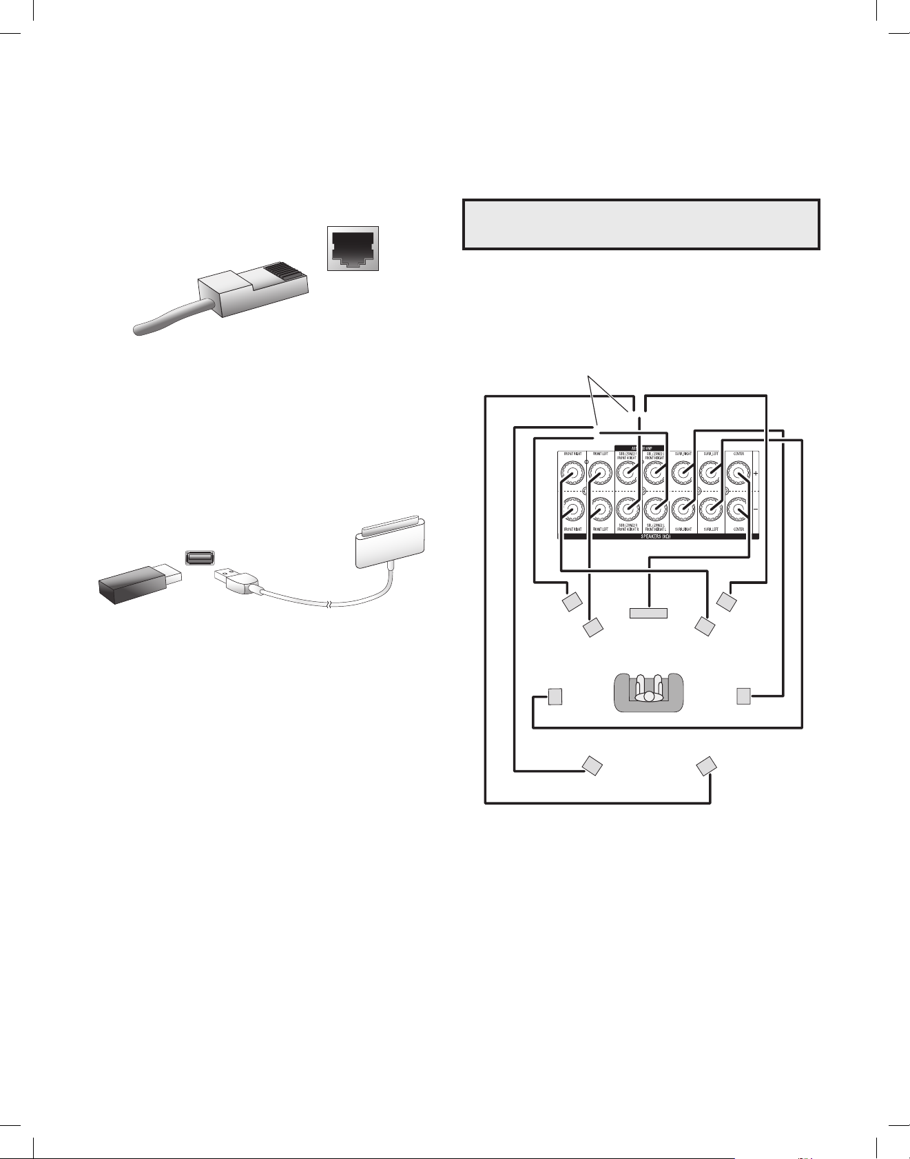
Connect Your Speakers
After you have placed your loudspeakers in the room as explained in Place Your Speakers,
on page 11, connect each speaker to its color-coded terminal on the AVR as explained
in Speaker Connections, on page 12. Connect the speakers as shown in the illustration.
AVR 1710S/AVR 171S only:
Connect Surround Back L/R Speakers
-OR- Front Height L/R Speakers Here
IMPORTANT: Do not connect a PC or other USB host/controller to the AVR’s USB
port, or you may damage both the AVR and the other device.
FHL
(AVR 1710S/
AV
NOTE: If you installed front height speakers, connect t hem as shown for the SBL an
BR speakers.
FL
SL
SBL
(AVR 1710S/
AV
R 171S only)
C
FHR
(AVR 1710S/
AVR 171S only)R 171S only)
FR
SR
SBR
(AVR 1710S/
AVR 171S only)
14
TR00306_AVR_OM_161S and 171S_EMEA_B.indb 14 26/05/15 2:29 pm
Page 15
AVR
ENGLISH
AVR 1710S/AVR 171S AVR 1610S/AVR 161S
Making Connections
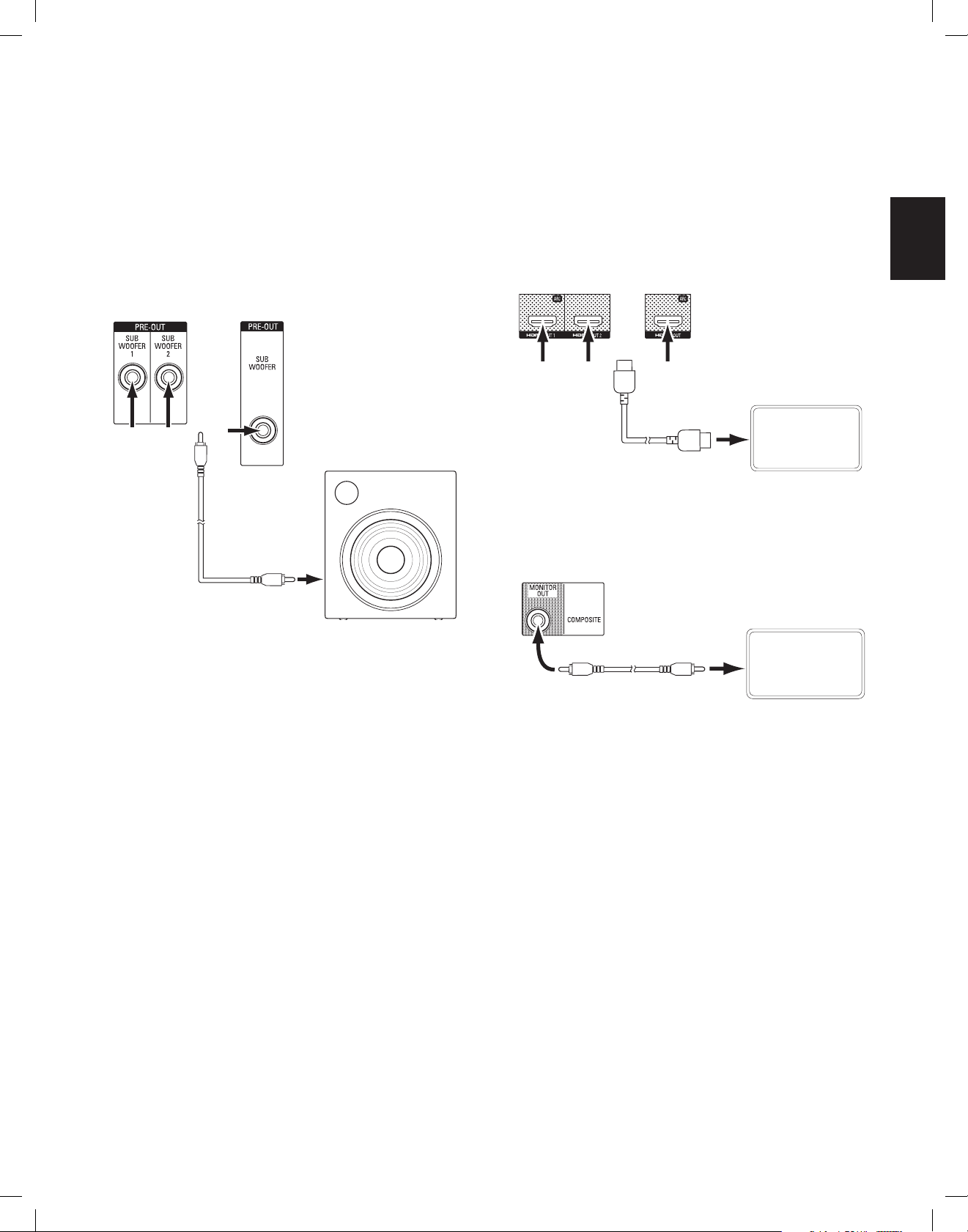
Connect Your Subwoofer
Use a single RCA audio cable to connect the AVR’s Subwoofer connector to your
subwoofer as explained in Subwoofer Connections, on page 12. NOTE: The AVR 1710S and
AVR 171S provide connections for two subwoofers. See Manual Speaker Setup: Number
of Speakers, on page 31, for information about activating the two subwoofer outputs.
Consult your subwoofer’s user manual for specific information about making connections
to it.
AVR 1710S/
AVR 171S
Use either
connector
AVR 1610S/
AVR 161S
Powered
Subwoofer
Single
RCA Audio
Cable
(not
supplied)
Connect Your TV or Video Display
If your TV has an HDMI connector and you have HDMI source devices: Use an HDMI
cable (not included) to connect it to the AVR’s HDMI Monitor Out connector. The AVR
1710S and AVR 171S provide HDMI connections for two TVs (only HDMI Out 1 has ARC
and enables you to view the AVR’s on-screen menus). This will provide the best possible
picture quality.
Use HDMI
Out 1 for
the primary
display
If your TV does not have an HDMI connector or if your TV does have an HDMI
connector but you are connecting some source devices with only composite video
connectors: Use a composite video cable (not included) to connect the AVR’s Composite
Monitor Out connector to your TV’s composite video connector.
AVR Composite
Monitor Out Connector
HDMI Cable
(not supplied)
TV
TV
Composite Video Cable
(not supplied)
NOTE: If you use only the composite video connection to your TV, you will not be able to
view the AVR’s on-screen menus.
15
TR00306_AVR_OM_161S and 171S_EMEA_B.indb 15 26/05/15 2:29 pm
Page 16
AVR
Connect Your Audio and Video Source Devices
Source devices are components where a playback signal originates, e.g. a Blu-ray Disc™
or DVD player; a cable, satellite or HDTV tuner; etc. Your AVR has several different types of
input connectors for your audio and video source devices: HDMI, composite video, optical
digital audio, coaxial digital audio and analog audio. The connectors are not labeled for
specific types of source devices; they are labeled numerically, so you can connect your
devices according to your individual system’s makeup.
Your AVR’s various source buttons have default assignments to different input connectors
(listed in the “Default Connector(s)” column of the table below). For ease of setup, you
should connect each source device to the connector where the corresponding default
source button is assigned (e.g., connect your Blu-ray Disc player to HDMI 2).
However, you can connect your source devices as you wish and re-assign any of the
input connections to any of the Source Buttons listed in the table according to where you
actually connect each of your source devices.
As you connect your various source devices, fill out the “Connected Component” column
in the table – it will make it easier for you to assign the various source buttons after
you have completed making all of the connections. (You will make any changes to the
source-button assignments and fill in the “Assigned Connector(s)” column later in the
setup process.)
Note: You cannot assign connectors to the Network, Radio, TV and USB source buttons.
Source Buttons and Assigned Connectors
Source Button Default Connector(s) Assigned Connector(s) Connected Device
MHL HDMI 1
Disc HDMI 2
Making Connections
Cable-Sat HDMI 3
STB HDMI 4
Game HDMI 5
Audio None/Analog 2
Aux Composite 1/Analog 1
Monitor Output Connector Connected Device
HDMI Out 1
(AVR 1710S/AVR 171S only)
Composite Video Monitor Out
HDMI Out 2
16
TR00306_AVR_OM_161S and 171S_EMEA_B.indb 16 26/05/15 2:29 pm
Page 17
AVR
ENGLISH
AVR HDMI/MHL In Connector
Roku
Streaming Stick
quipp
p
Making Connections
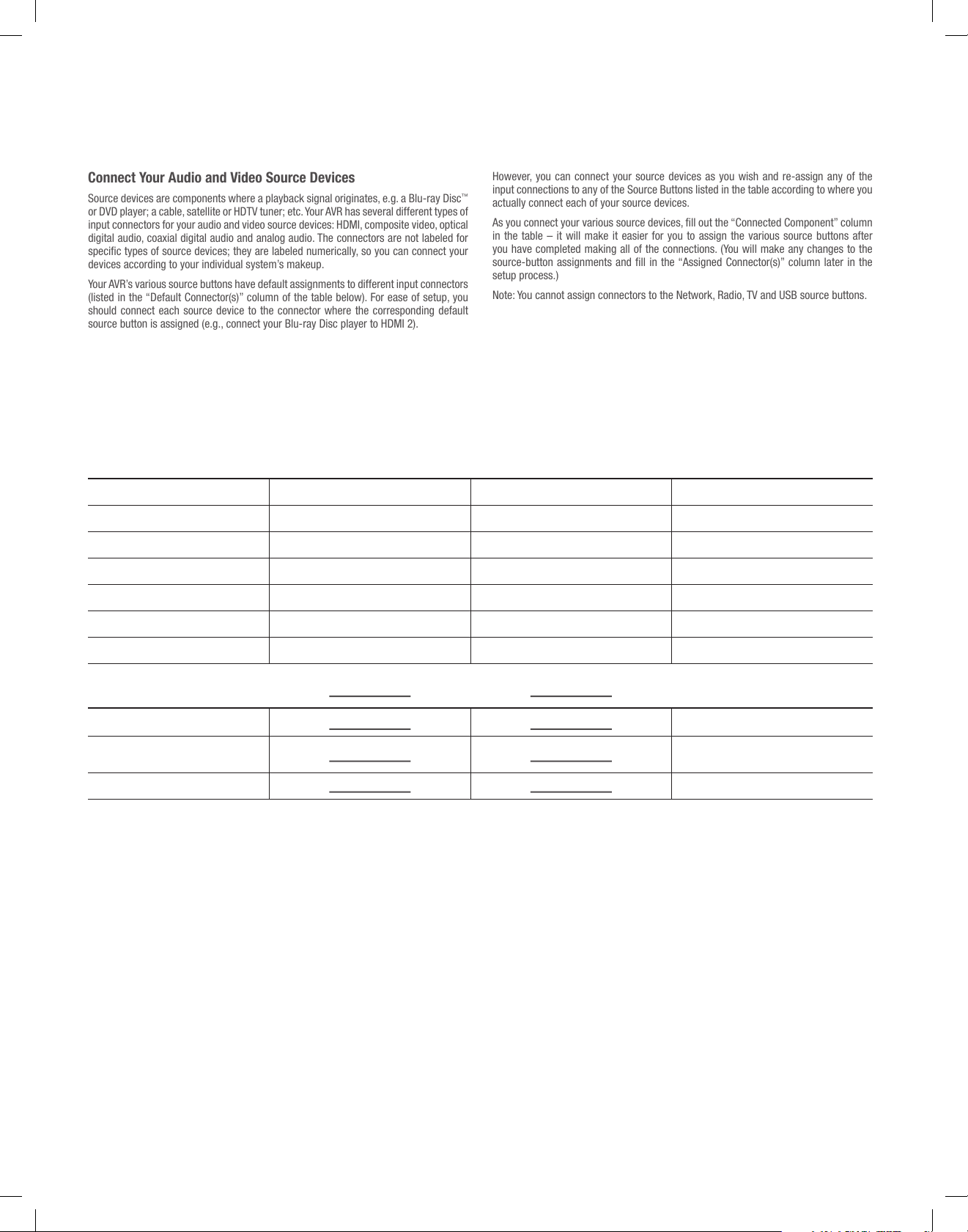
Roku Streaming Stick™:
If you have a Roku Streaming Stick device, insert it into the AVR’s HDMI/MHL In connector.
NOTE: Do not insert the Roku Streaming Stick device into any other HDMI In connector.
®
Connect Your HDMI Devices
If any of your source devices have HDMI connectors, using them will provide the best
possible video and audio performance quality. Since the HDMI cable carries both digital
video and digital audio signals, you do not have to make any additional audio connections
for devices you connect via an HDMI cable.
AVR HDMI Connectors
Connect Your Composite Video Devices
Use composite video connectors for video source devices that don’t have HDMI
connectors. You will also need to make an audio connection from the source device to
the AVR.
AVR Composite In Connectors
Composite Video Cable (not included)
To Composite
Video Output
Composite-Equipped Source Device
Connect Your Optical Digital Audio Devices
If your non-HDMI source devices have optical digital outputs, connect them to the AVR’s
optical digital audio connectors. NOTE: Make only one type of digital connection (HDMI,
optical or coaxial) from each device.
AVR Digital
Audio Connectors
NOTE: If you have HDMI devices (such as an Internet connection) already connected
directly to your TV, you can feed their sound to the AVR via the HDMI Out connector’s
Audio Return Channel, and they will not require additional connections to the AVR. AVR
1710S/AVR 171S only: Only the HDMI Out 1 connection has the Audio Return Channel.
HDMI Cable
(not supplied)
To HDMI
Output
HDMI-E
ed Source Device
Optical Digital Audio
Cable (not supplied)
tical-Equipped Source Device
O
To Optical Digital
Audio Output
17
TR00306_AVR_OM_161S and 171S_EMEA_B.indb 17 26/05/15 2:29 pm
Page 18
AVR
quipp
AVR Digital
A
Analog
Analog Source Device
AVR 1710S/AVR 171S
Analog
AVR 1610S/AVR 161S
Connectors
AM Antenna
Making Connections
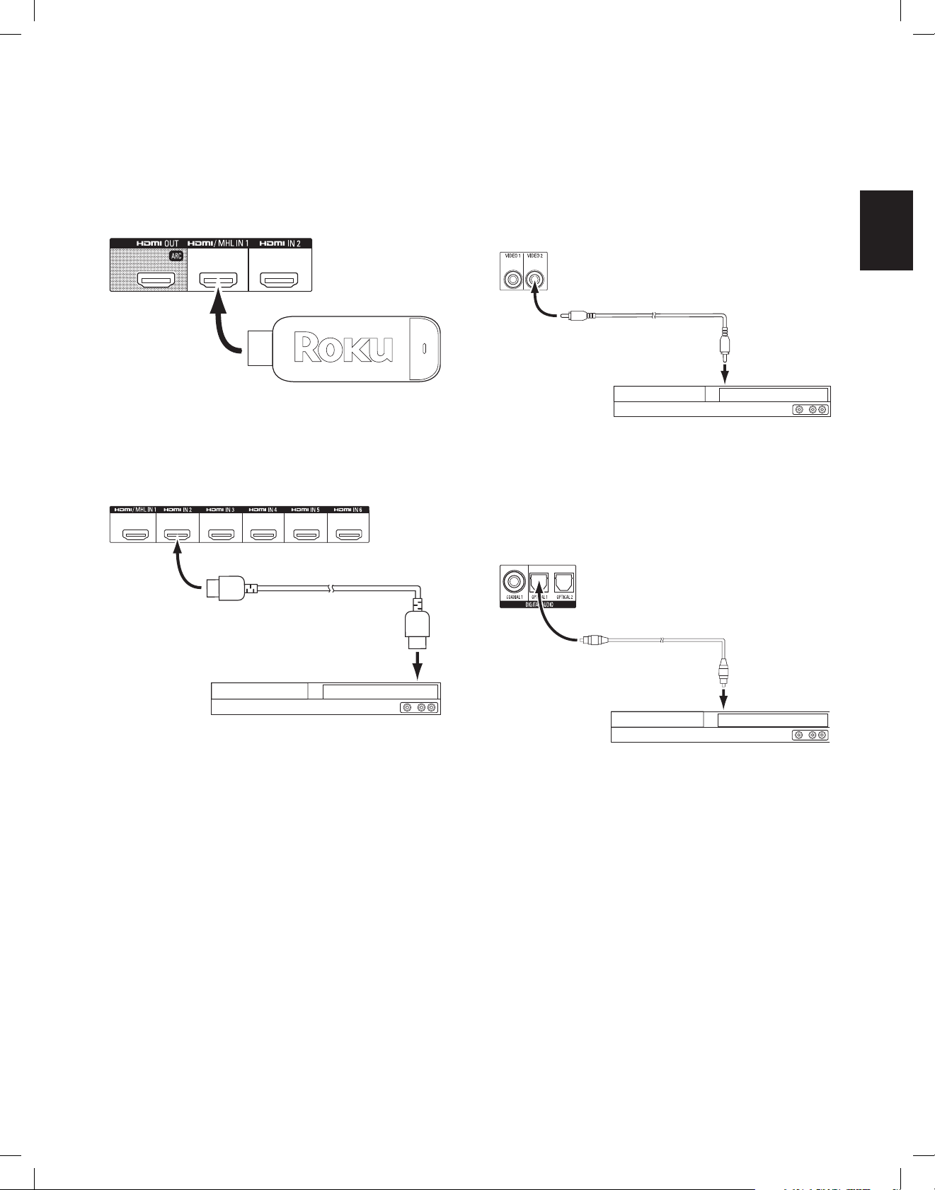
Connect Your Coaxial Digital Audio Devices
If your non-HDMI source device has a coaxial digital output, connect it to the AVR’s
coaxial digital audio connector. NOTE: Make only one type of digital connection (HDMI,
optical or coaxial) from each device.
udio Connectors
Connect Your Analog Audio Devices
Use the AVR’s analog audio connectors for source devices that don’t have HDMI or digital
audio connectors. NOTE: If you’re installing a multizone system, make analog audio
connections for any source devices you want to be able to listen to in Zone 2. Only analog
sources are available in Zone 2.
Audio Connectors
Coaxial Digital Audio
Cable (not supplied)
Coaxial-E
Analog Audio Connectors
To Coaxial Digital
Audio Output
ed Source Device
USB and iOS Devices
Use the AVR’s front-panel USB port to connect an iPod, iPhone or iPad using an Apple
cable (not supplied) or to directly connect a USB memory stick. You can play audio files
from the device or memory stick and use the AVR’s remote to control playback.
AVR
Front-Panel
USB Port
USB
Memory
Stick
Apple Cable
(not supplied)
Connect to Your Home Network
Use a Cat. 5 or Cat. 5E cable (not supplied) to connect the AVR’s Network connector to
your home network to enjoy Internet radio and content from DLNA-compatible devices
that are connected to the network.
AVR
Network
Connector
Cat. 5/5E Cable (not supplied)
Network
Modem
To Home
Network
and Internet
Stereo Audio Cable
(not supplied)
To Stereo
Audio Output
Connect the Radio Antennas
• Connect the supplied FM antenna to the AVR’s FM 75Ω antenna connector. For the
best reception, extend the FM antenna as far as possible.
• Bend and fold the base of the supplied AM antenna as shown and connect the
antenna wires to the AVR’s AM and Gnd connectors. (You can connect either wire to
either connector.) Rotate the antenna as necessary to minimize background noise.
AVR 1710S/
AVR171S
Antenna
AVR 1610S/
AVR161S
Antenna
Connectors
(supplied)
Bend and fold base
FM Antenna (supplied)
18
TR00306_AVR_OM_161S and 171S_EMEA_B.indb 18 26/05/15 2:29 pm
Page 19
AVR
ENGLISH
ENGLISH
AVR
Making Connections
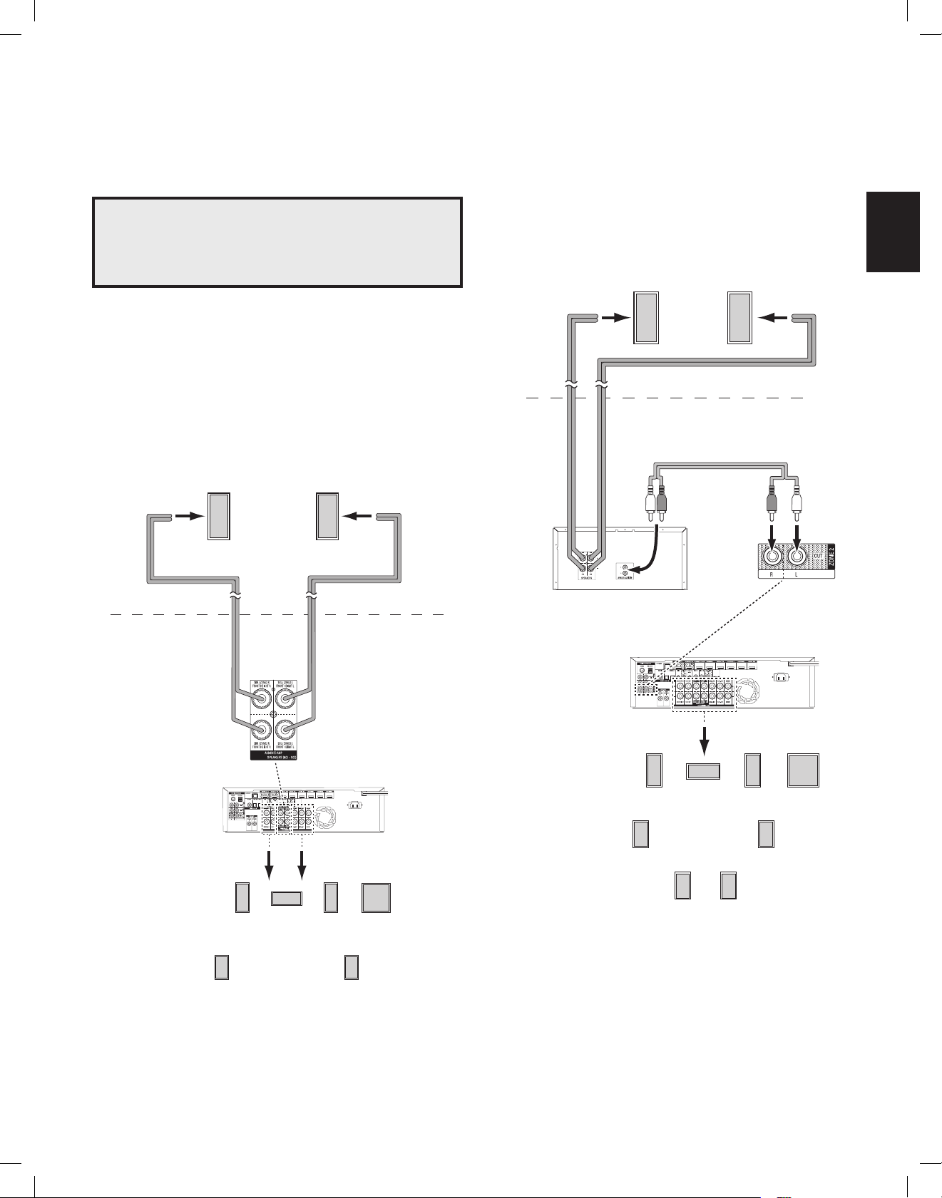
Install a Multizone System
Making Connections
AVR 1710S/AVR 171S only: Install a Multizone System
IMPORTANT SAFETY NOTE: Installing a multizone system typically requires
running cables inside walls. Always comply with the appropriate safety codes
when installing concealed wiring, particularly all applicable building codes.
Failure to do so may present a safety hazard. If you have any doubt about
your ability to work with electrical wiring, hire a licensed electrician or custom
installer to install the multizone system.
NOTE: Only the following analog audio sources are available to Zone 2: the internal radio,
an iPod/iPhone device or a USB memory device inserted in the AVR’s USB port and up to
two source devices connected to the rear-panel Analog Audio In 1 and 2 connectors.
Your AVR offers two different methods of distributing audio to other areas in your home.
Each requires different connections:
A. Connect the Zone 2 speakers directly to the Assigned Amp Speaker Output
connectors. Assign the Assigned Amp channels to power the Zone 2 speakers (see
Manual Speaker Setup, on page 30). This method allows you to power a single pair of
speakers for Zone 2.
This method offers the benefit of reduced cost and complexity, but your home theater
system will be limited to 5.1 channels – the AVR will automatically downmix the playback
of programs recorded in 6.1 or 7.1 channels to 5.1 channels.
Zone 2
Speakers
B. Connect an external amplifier to the AVR’s Zone 2 Out connectors. This method
offers the benefit of retaining a 7.1-channel home theater in the main room simultaneously
with multizone operation, although it does require an additional amplifier for Zone 2.
We recommend that you place the Zone 2 amplifier in the same room as the AVR so that
you can use a short length of stereo audio cable along with a long run of speaker wire to
the remote room. A long run of stereo audio cable would increase the chance of signal
degradation. Depending on your Zone 2 amplifier you can distribute the audio signal to a
single pair of speakers or to several pairs placed in different rooms.
Speaker Wire
(not supplied)
Zone 2
Speakers
Speaker Wire
(not supplied)
Stereo Audio Cable
(not supplied)
Zone 2
Main Room
Speaker Wire
(not supplied)
Assigned
Amp
Speaker
Connectors
AVR
FL
5.1-Channel
Home Theater
Speaker System
SL SR
C
Speaker Wire
(not supplied)
FR LFE
Zone 2
Main Room
Zone 2 Amplifier
(not supplied)
AVR
FL
SL
C
7.1-Channel
Home Theater
Speaker System
SBL SBR
FR LFE
SR
19
19
TR00306_AVR_OM_161S and 171S_EMEA_B.indb 19 26/05/15 2:29 pm
Page 20
AVR
AVR IR In Jack
Zone 2
Main Room
AVR
Making Connections
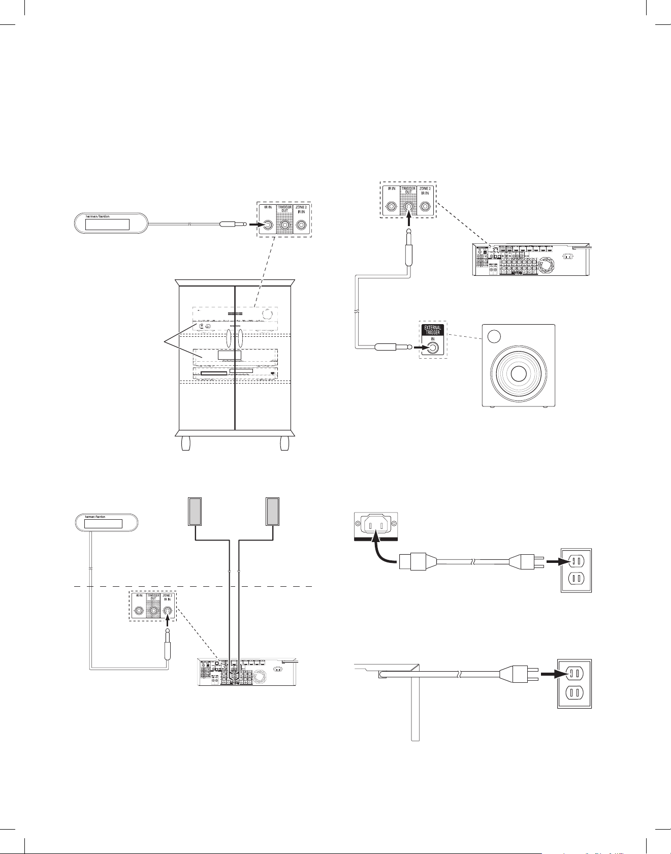
Connect IR Equipment
The AVR is equipped with a Remote IR Input connector that lets you remotely control the
AVR in a variety of situations:
• When you place the AVR inside a cabinet or facing away from the listener, connect
an external IR receiver, such as the optional Harman Kardon HE 1000, to the AVR’s
IR In jack.
External IR
Receiver
AVR and Source Devices
Installed Inside of Cabinet
Connect the Trigger Output
If your system has equipment that can be controlled by a DC trigger signal, connect it to
the AVR’s Trigger Out connector with a mono 1/8-inch (3.5mm) mini-plug interconnect
cable. The AVR will supply a 12V DC (100mA) trigger signal at this connection whenever
it is powered on.
AVR
Mono 1/8-inch (3.5mm)
Mini-Plug Interconnect
(not supplied)
Device with
Trigger In Connector
• If you install a multizone system (AVR 1710S/AVR 171S only), connect an IR control
device to the Zone 2 IR In connector for remote-room control of the multizone
system, source devices and volume in the remote zone.
External IR Receiver
If a source device is shared with the main listening area, any control commands issued
to that source will also affect the main room.
Zone 2 Speakers
Connect to AC Power
AVR 171S/AVR 161S:
Connect the supplied AC power cord to the AVR’s AC Input connector and then to a
working, non-switched AC power outlet.
AVR
AC Input
Connector
AC Power
Outlet
Power Cord (supplied)
AVR 1710S/AVR 1610S:
Connect the AVR’s power cord to a working, non-switched AC power outlet.
AC Power
AVR
Power Cord
Outlet
20
TR00306_AVR_OM_161S and 171S_EMEA_B.indb 20 26/05/15 2:29 pm
Page 21
AVR
ENGLISH
Set Up the Remote Control
Set Up the Remote Control
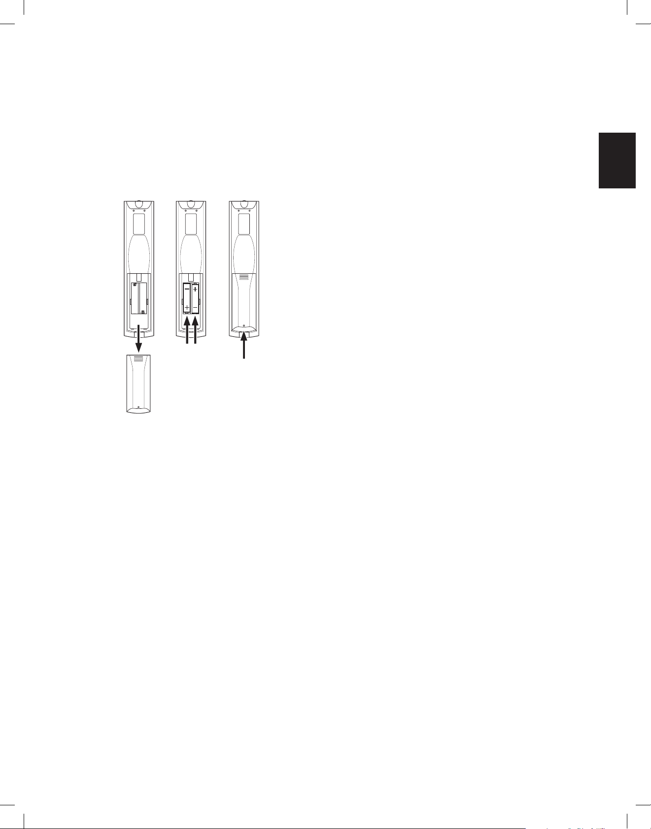
Install the Batteries in the Remote Control
Remove the remote control’s battery cover, insert the two supplied AAA batteries as
shown in the illustration, and replace the battery cover.
1. Remove
Cover
2. Insert
Batteries
3. Replace
Cover
2. Look up the code numbers for the device in Tables A10 – A20 in the Appendix. Write all
the applicable code numbers in a convenient place.
3. Press the Source Selector button for the device and hold it as it glows red, goes dark
and glows red again. Then release it. The remote is now in the Programming mode.
NOTE:
The remote will remain in the Programming mode for 20 seconds. If you do not
complete Step 4 within 20 seconds, the remote will exit the Programming mode, and you
will need to repeat Step 3.
4. Aim the remote at the source device and use the remote’s Number buttons to enter a
code number from Step 1, above.
a) If the device turns off, press the Source Selector button again to save the code. The
Source Selector button will flash, and the remote will exit the Programming mode.
b) If the device does not turn off, enter another code number.
c) If you run out of code numbers for a device, you can search through all of the codes
in the remote’s library for dervices of its type by pressing the remote’s Up button
repeatedly until the device turns off. When it does, press the Source Selector button
to save the code.
5. Check that other functions control the device correctly. Sometimes manufacturers use
the same Power code for several models, while other function codes vary. Repeat this
process until you’ve programmed a satisfactory code set that operates most of the
device’s functions.
6. If you searched through the remote’s code library to find the code, you can find out
which code number you have programmed by pressing and holding the Source Selector
button to re-enter the Programming Mode. Then press the remote’s OK Button, and the
Source Selector button will flash in the code sequence. One flash represents “1,” two
flashes for “2,” and so forth. A series of quick flashes represents “0.” Record the code
number programmed for each device in Table A7 in the Appendix.
Repeat Steps 3 – 6 for each source device you want to control with the AVR remote.
Program the Remote to Control Your Source Devices and TV
You can program your AVR remote to control many brands and models of audio/video
source devices and TVs. The remote is also ready to operate your iPod or iPhone when it
is connected to the AVR’s front-panel USB port.
Each of the remote’s Source Selector buttons has been preprogrammed to control certain
types of source devices:
Cable/Sat: Controls cable TV and satellite TV tuner boxes
Disc: Controls Blu-ray Disc and DVD players
Radio:
Controls the AVR’s built-in FM/AM tuner
TV:
Controls TVs and video displays
USB:
Browses compatible media on an Apple iOS device that is connected to, or a USB
device that is inserted in the AVR’s USB port Note: Does not require programming.
DVR:
Controls TiVo® recorders
Game:
Controls video-game consoles
Media Server:
Network:
home network and on vTuner (Internet Radio). Note: Does not require programming.
AUX:
Although the Source Selector buttons are preprogrammed for the device types listed
above, you can reassign a Source Selector button to a different device type. See
Reassigning a Source Selector Button for a Different Device Type, on page 21.
Once you have programmed the remote, you can switch the remote’s control mode to
access the functions for a particular device by pressing the remote’s Source Selector
button for that device.
Follow these steps to program the Source Selector buttons for your source devices:
1. Turn on the source device you want to program the remote to control.
Controls media servers
Browses compatible media on DLNA-compatible devices connected to your
Controls HDTV tuner boxes, CD players, VCRs and PVDs.
Reassigning a Source Selector Button for a Different Device Type
You can reassign a Source Button to control a different device type (for example, you can
program the Media Server button to control a DVD player).
1. Turn on the source device you want the remote to control.
2. Look up the code numbers for the device in Tables A12 – A22 in the Appendix. Write all
the applicable code numbers in a convenient place.
3. Press the Source Selector button you want to override and hold it for three seconds
as it glows red, goes dark and glows red again. Then release it. The remote is now in
the Programming mode.
4. Press the Source Selector button that corresponds to the source device’s type (i.e.,
for a DVD player, press the Blu-ray button). The Source Selector button you pressed in
Step 3 will flash once.
5. Aim the remote at the source device and use the remote’s Number buttons to enter a
code number from Step 2, above.
a) If the device turns off, press the Source Selector button from Step 3 again to
save the code. The Source Selector button will flash, and the remote will exit the
Programming mode.
b) If the device does not turn off, enter another code number.
c) If you run out of code numbers for a device, you can search through all of the codes
in the remote’s library for devices of its type by pressing the remote’s Up button
repeatedly until the device turns off. When it does, press the Source Selector button
from Step 3 to save the code.
Most of the button labels on the AVR remote describe each button’s function when the
remote is used to control the AVR. However, the button may perform a different function
when used to control another device. Refer to the Remote Control Function List, Table
A13 in the Appendix.
21
TR00306_AVR_OM_161S and 171S_EMEA_B.indb 21 26/05/15 2:29 pm
Page 22
AVR
Set Up the AVR
Set Up the AVR
In this section, you will configure the AVR to match your actual system’s makeup. Although
it’s possible to configure the AVR using only the remote and the messages on the AVR’s
front-panel display, it is easier if you use the on-screen menu system.
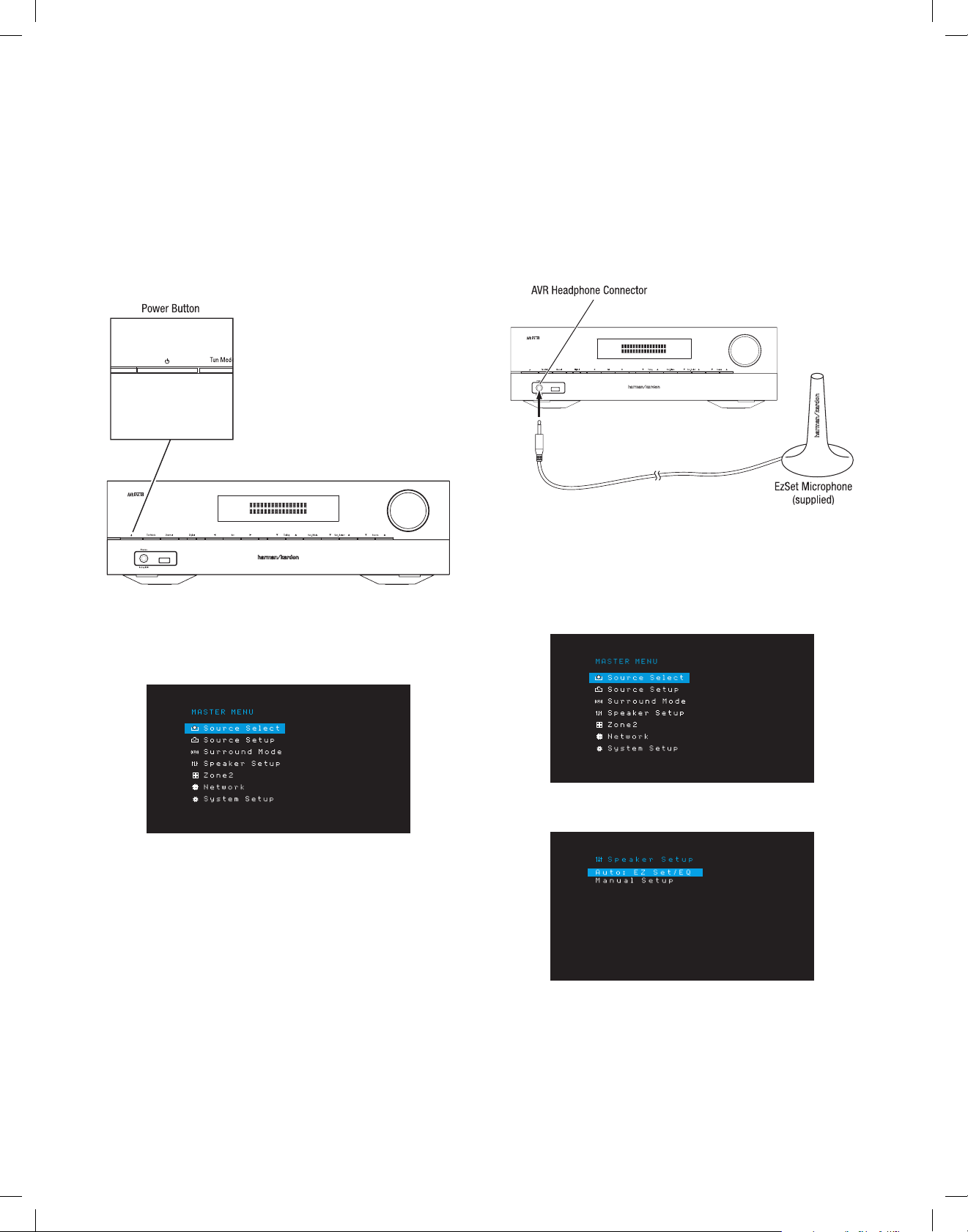
Turn On the AVR
Press the front-panel Power button.
Using the On-Screen Menu System
To access the menu system, press the OSD/Menu button on the remote. The OSD/Menu
Menu will appear, and if a video source is playing, the menu will automatically re-size so
the picture will be visible behind the menu.
Before beginning the following setup steps, all loudspeakers, a video display and all
source devices should be connected. You should be able to turn on the AVR and view the
main menu when you press the AVR button. If necessary, reread the Making Connections
and Set Up the Remote sections before continuing.
Configure the AVR for Your Speakers
1. Plug the supplied EzSet/EQ microphone into the AVR’s Headphone connector.
2. Place the microphone at ear height in your listening position.
3. Set the volume control on your subwoofer to approximately the halfway point.
4. Turn on your TV and select the TV input where you connected the AVR in Connect Your
TV or Video Display, on page 15.
5. Press the remote control’s AVR button. The AVR’s on-screen display (OSD) Main Menu
screen will appear on the TV.
6. Use the remote’s Up/Down/Left/Right and OK buttons to select “Speaker Setup.”
NOTE:
The actual on-screen menus may differ slightly from the illustrations in this
manual.
The Main Menu system consists of six submenus: Source Select, Source Setup, Surround
Mode, Speaker Setup, Network and System Setup. (The AVR 1710S/AVR 171S also have
a Zone 2 submenu.) Use the Up/Down/Left/Right buttons on the remote or the front panel
to navigate the menu system, and press the OK button to select a menu or setting line,
or to enter a new setting.
The current menu, setting line or new setting will appear in the front-panel Message
Display, as well as on screen.
To return to the previous menu or exit the menu system, press the Back/Exit button. Be
certain all settings are correct, as any changes you have made will be retained.
Most users should follow the instructions in this Set Up the AVR section to configure a
basic home theater system. You may return to these menus at any time to make additional
adjustments, such as those described in the Advanced Functions section, on page 29.
22
TR00306_AVR_OM_161S and 171S_EMEA_B.indb 22 26/05/15 2:29 pm
Page 23
AVR
ENGLISH
Set Up the AVR
7. Select “Auto: EzSet/EQ”.
8. If you have a subwoofer connected, select “Yes with Sub.” Otherwise, select “Yes
without Sub.”
9. For AVR 1610S/AVR 161S, or for AVR 1710S/AVR 171S’s in 5.0- or 5.1-channel
systems, select “5.0” or “5.1” in the Speaker Configuration screen. For AVR 1710S/
AVR 171S’s in 7.0- or 7.1-channel systems, select “7.0” or “7.1.”
10. The test will begin. Make sure that the room is quiet while the test noise is playing
through the speakers.
11. When the test finishes, select “Done” to exit.
NOTES:
• If there are fewer than five main speakers in your system, do not use the EzSet/
EQ process. Instead, proceed as described in Manual Speaker Setup, on page 30.
• If you are using an AVR 1710S/AVR 171S in 6.0- or 6.1-channel configuration with a
single surround back speaker, do not use the EzSet/EQ process. Instead, proceed as
described in Manual Speaker Setup, on page 30.
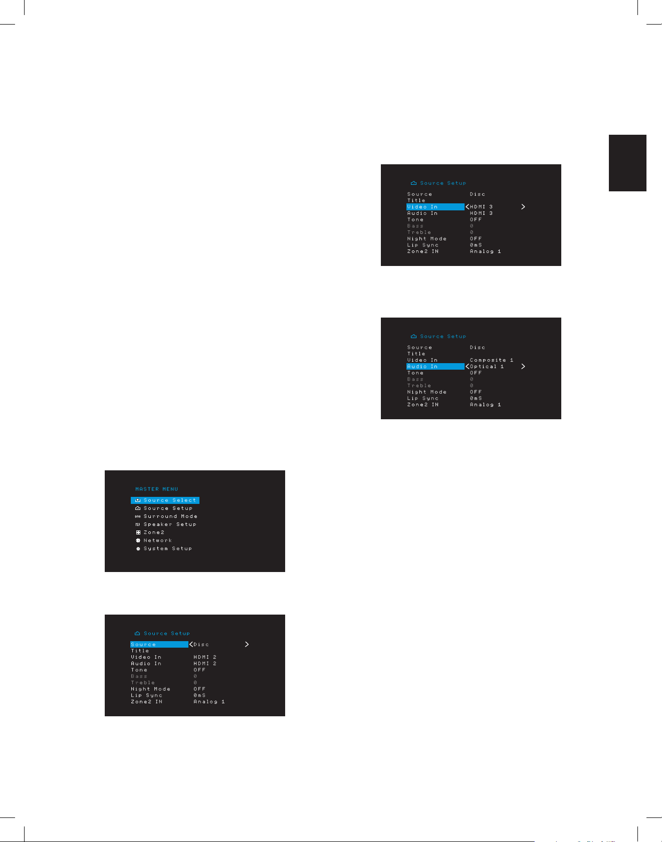
Set Up Your Sources
The Source Setup menu lets you assign the correct physical audio and video connections
to each source and lets you set many audio and video playback features for each source.
IMPORTANT: The “Video In” and “Audio In” settings are not optional and must
be adjusted before you use your AVR to enable playback of each source. You can
adjust the other settings later. See System Settings, on page 34, for complete information
about adjusting all of the Settings menu options.
1. Review the input connections you listed on the Source Buttons and Assigned
Connectors table, on page 16. Note what changes (if any) you want to make from the
default connector assignments that appear on the list.
2. Turn on your TV and select the TV input where you connected the AVR in Connect Your
TV or Video Display, on page 15.
3. Press the remote control’s OSD/Menu button. The AVR’s OSD setup menu will appear
on the TV. (Note: If you have used a composite video connection to your TV, the OSD
menus will not appear on your TV. Follow the steps below using the AVR’s front-panel
display.)
4. Use the remote’s arrow and OK buttons to select “Source Setup,” and use the left/right
arrow buttons to select a source button with connectors that you want to re-assign.
5. Select “Video In” and select the video input connector you want to assign to the source
button. Press the OK button. NOTE: If you select an HDMI connector as the video input
connector, the audio input connector will automatically change to the same HDMI
connector.
6. If you have not selected an HDMI connector for Video In, select “Audio In” and select
the audio input connector you want to assign to the source button. Press the OK button.
You cannot use a different video input connector with an HDMI audio input connector.
7. Press the remote’s Back/Exit button and repeat steps 3 – 6 for the remaining source
buttons with connectors you want to re-assign.
Title: This selection lets you change the display name for the source, which is useful if
your source’s device type is different from the source’s preprogrammed name. Use the
Up/Down buttons to scroll forward or backward through the alphanumeric characters
until the desired character appears, then use the Left/Right buttons to move the cursor to
the next or previous position. Move the cursor again to leave a blank space. (Your name
can have a maximum of 10 characters.) When you have finished, press the OK Button.
The new name will appear on the AVR’s front panel and throughout the on-screen menu
system.
Tone: This setting determines whether the treble and bass controls are active for the
source. When it’s set to Off, the tone controls are out of the circuit, with no changes to the
sound. When it’s set to On, the bass and treble controls are in the circuit.
Treble/Bass: These settings boost or cut the treble or bass frequencies by up to 10dB,
in 2dB increments. Use the Left/Right buttons to change the setting. The default setting
is 0dB.
Night Mode: This setting activates Night mode for the source, which works with specially
encoded Dolby Digital discs or broadcasts. Night mode compresses the audio so that
louder passages are reduced in volume to avoid disturbing others, while dialogue
remains intelligible. The following settings are available:
• Off: No compression is applied. Loud passages in the program remain as they were
recorded.
• Mid: Loud passages in the program are reduced moderately in volume. Dolby True
HD stream is compressed automatically as set by the incoming stream.
• Max: Loud passages in the program are reduced more in volume.
23
TR00306_AVR_OM_161S and 171S_EMEA_B.indb 23 26/05/15 2:29 pm
Page 24
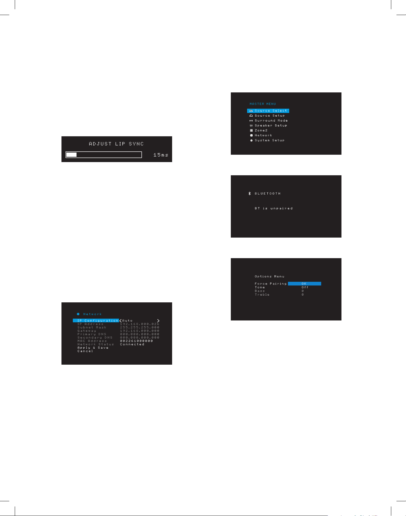
AVR
Set Up the AVR
Lip Sync: This setting lets you resynchronize the audio and video signals from the source
to eliminate a “lip sync” problem. Lip-sync issues can occur when the video portion of a
signal undergoes additional processing in either the source device or the video display.
Use the Left/Right buttons to delay the audio by up to 180ms. (The active source’s video
will be visible behind the OSD menu, allowing you to synchronize the audio with the
picture.)
You can also make lip sync adjustments without activating the AVR’s OSD menus.
Pressing the remote’s Delay button will display the Lip Sync menu bar on the TV,
superimposed at the bottom of the video. Use the Left/Right buttons to delay the audio
until it is synchronized with the picture.
Zone 2 In (AVR 1710S/AVR 171S only): This setting determines the audio source for
Zone 2 of a multizone system. Select the analog audio input the source is connected to.
Digital audio is not available to the multizone system.
To configure the next source, press the Back/Exit button, then return to the Setup Source
line of the Main Menu. When you have finished configuring all sources, press the Back/
Exit button to clear the menus from view.
Set Up the Network
To play MP3 or WMA media located on DLNA-compatible devices connected to the
network, use the AVR’s internal Internet radio tuner or listen to sources via AirPlay (AVR
1710S/AVR 171S only), the AVR must be connected to your home network and you must
join them with the network.
If your network uses an automatic IP address, you should not have to perform any
network setup procedures. Once you connect the AVR to your home network, the network
should automatically assign the AVR an IP address, and the AVR should automatically join
your network.
If your AVR does not automatically join your network (in which case the AVR will display a
“Not Connected” message when you press the Network source button):
1. Press the OSD/Menu button, select System Setup, then select Network.
2. The Network menu will appear.
Pair the AVR with Your Bluetooth Device
1. Press the OSD/Menu button and select “Source Select.”
2. Scroll to “Bluetooth” and select it. The OSD will display that Bluetooth is unpaired.
3. Press the remote’s Option /Info button. The Bluetooth Options Menu will appear.
3. Select IP Configuration, then press the Right button button twice to cycle the setting
from “Auto” to “Manual” and back to “Auto.”
4. Select Apply & Save. The AVR will attempt to connect to the network.
5. If the AVR again fails to connect to the network, you may need to enter your network’s
settings manually. You may need to obtain your network’s settings from your ISP or
network administrator.
NOTE: We recommend that you directly connect the AVR to a home-network router so
that it can directly access the Internet for Internet radio, or access devices on the network
for playback of content stored on the devices (see Listening to Media via Your Home
Network, on page 28, for more information).
NOTE: If you have trouble connecting to the network at any time, cycle the AVR into
the Sleep mode, and then turn it back on.
24
4. Select “Force Pairing > OK” and press the OK button. The AVR will enter the pairing
mode.
5. Open your Bluetooth device’s pairing menu. The AVR will appear on your device’s
pairing menu as “HK AVR.”
• If your device requires a passcode, use 0000.
6. Pair your device with the AVR. Once paired, press the OSD/Menu button to exit the
menu.
To stream audio from the paired Bluetooth device:
1. Press the OSD/Menu button.
2. Select the Source Select menu.
3. Select Bluetooth from the source list.
TR00306_AVR_OM_161S and 171S_EMEA_B.indb 24 26/05/15 2:29 pm
Page 25
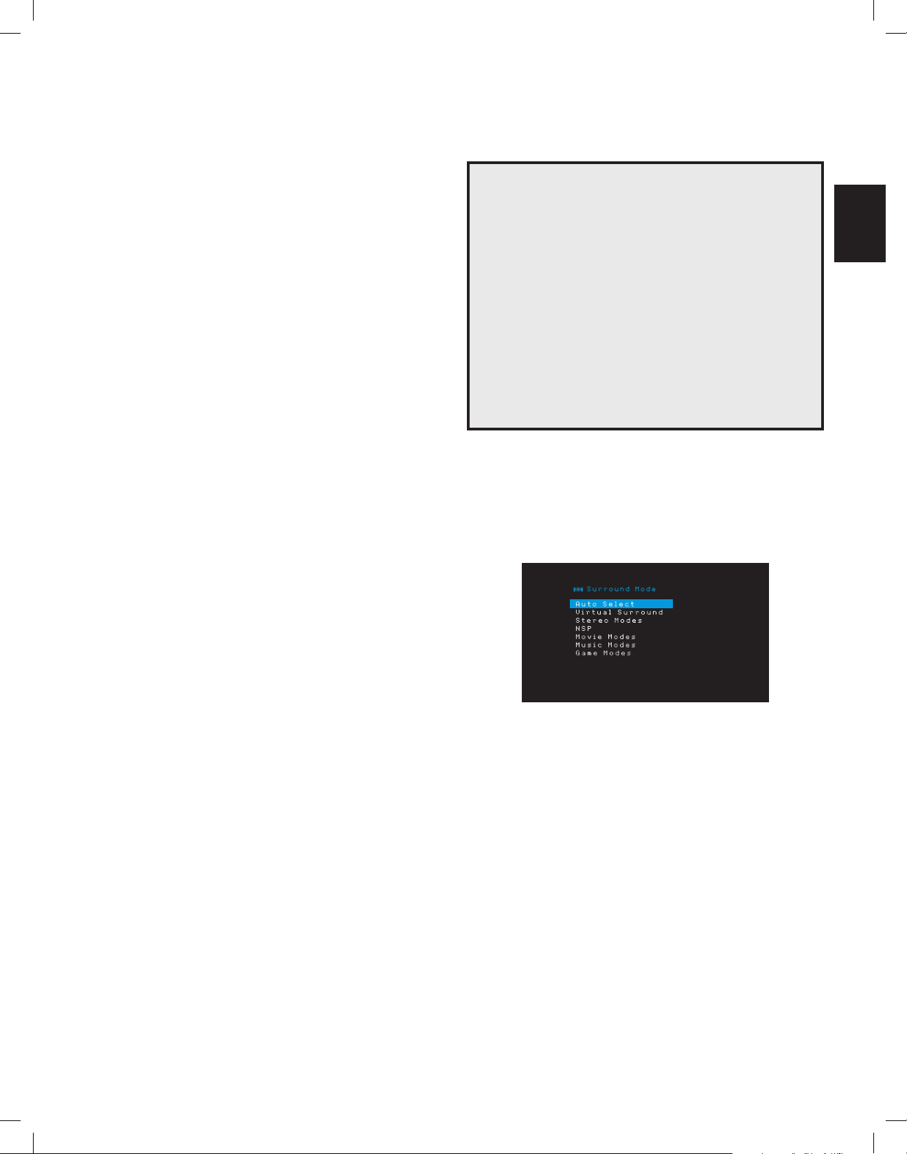
AVR
ENGLISH
Operating Your AVR
Operating Your AVR
Now that you have installed your components and completed a basic configuration, you
are ready to begin enjoying your home theater system.
HARMAN Remote App
For easy control of your AVR with your hand-held device, download the free Harman
Kardon Remote app from iTunes App Store for compatible Apple products, or from Google
Play for compatible Android powered smartphones.
The Harman Kardon Remote App controls virtually all the functions of AVR 1710S, AVR
171S, AVR 1610S and AVR 161S AVRs that are connected to the same network as the
device that has the app installed. With this easy-to-use app you can turn the AVR on or
off, select a source, control the volume and virtually any other function. You can also
access and navigate all of the AVR’s on-screen setup menus.
Controlling the Volume
Adjust the volume either by turning the front-panel Volume knob (clockwise to increase
volume or counterclockwise to decrease volume) or by pressing the Volume Up/Down
buttons on the remote. The volume is displayed as a negative number of decibels (dB)
below the 0dB reference point (–80dB – +10dB).
0dB is the maximum recommended volume for your AVR. Although it’s possible to turn
the volume to a higher level, doing so may damage your hearing and your speakers. For
certain more dynamic audio materials, even 0dB may be too high, allowing for damage
to equipment. Use caution with regard to volume levels.
To change the volume level display from the default decibel scale to a 0-to-90 scale,
adjust the Volume Units setting in the System Settings menu, as described in System
Settings, on page 34.
Muting the Sound
To mute all speakers and the headphones, press the Mute button on the remote. Any
recording in progress will not be affected. The MUTE message will appear in the display
as a reminder. To restore the sound, press the Mute button again, or adjust the volume.
Video Troubleshooting Tips
If there is no picture:
• Check the source selection and video input assignment.
• Check all connections for a loose or incorrect connection.
• Check the video input selection on the TV/display device.
Additional Tips for Troubleshooting HDMI Connections
• Turn off all devices (including the TV, the AVR and any source components).
• Unplug the HDMI cables, starting with the cable between the AVR and the TV,
and continuing with the cables between the AVR and each source device.
• Carefully reconnect the cables from the source devices to the AVR. Connect the
cable from the AVR to the TV last.
• Turn on the devices in this order: TV, AVR, source devices.
NOTE: Depending upon the particular components involved, the complexity of
the required communication between HDMI components may cause delays of
up to a minute in the completion of some actions, such as input switching or
switching between SD and HD channels.
Selecting a Surround Mode
Selecting a surround mode can be as simple or sophisticated as your individual system
and tastes. Feel free to experiment, and you may find a few favorites for
or program types. You can find more detailed information on surround modes in
Audio Processing and Surround Sound, on page 29.
To select a surround mode, press the OSD/Menu button and select Surround Mode. The
Surround Mode menu will appear.
certain sources
Listening Through Headphones
Plug the 1/4-inch stereo plug on a pair of headphones into the front-panel Phones
jack for private listening. The default HARMAN Headphone mode uses virtual surround
processing to emulate the sound of a 5.1-channel speaker system. Press the Surround
Modes button on the front panel or the remote to switch to the Headphone Bypass mode,
which delivers a conventional two-channel signal to the headphones. No other surround
modes are available for the headphones.
NOTE: You will be unable to listen through headphones if the iPod source is selected.
Selecting a Source
There are three different ways to select a source:
• Press the front-panel Source buttons to scroll through the sources.
• Using the on-screen menus, press the OSD/Menu button, highlight “Source Select”
and press the OK button. Scroll to the desired source and press the OK button.
• You can directly select any source by pressing its Source Selector button on the
remote.
The AVR selects the audio and video inputs assigned to the source, and any other settings
you made during setup.
The source name, the audio and video inputs assigned to the source, and the surround
mode will appear on the front panel. The source name and active surround mode will also
briefly appear on the TV screen.
Auto Select: For digital programs, such as a movie recorded with a Dolby Digital or DTS
soundtrack, the AVR will automatically use the soundtrack’s native surround format. For
two-channel analog and PCM programs, the AVR uses the HARMAN NSP mode.
Virtual Surround: When only two main speakers are present in the system, you can use
Virtual Surround to create an enhanced soundfield that virtualizes the missing speakers.
Stereo: When you want two-channel playback, select the number of speakers you want
to use for playback:
• “2 CH Stereo” uses two speakers.
• “5 CH Stereo” plays the left-channel signal through the front left and surround
left speakers, the right-channel signal through the front right and surround right
speakers, and a summed mono signal through the center speaker.
• “7 CH Stereo” (AVR 1710S/AVR 171S only) follows the same scheme as 5 CH Stereo
but adds the surround back left and surround back right speakers. This mode is
available only when the surround back speakers are present and have not been
reassigned to multizone or front height operation. See Audio Processing and
Surround Sound, on page 29, for more information.
25
TR00306_AVR_OM_161S and 171S_EMEA_B.indb 25 26/05/15 2:29 pm
Page 26
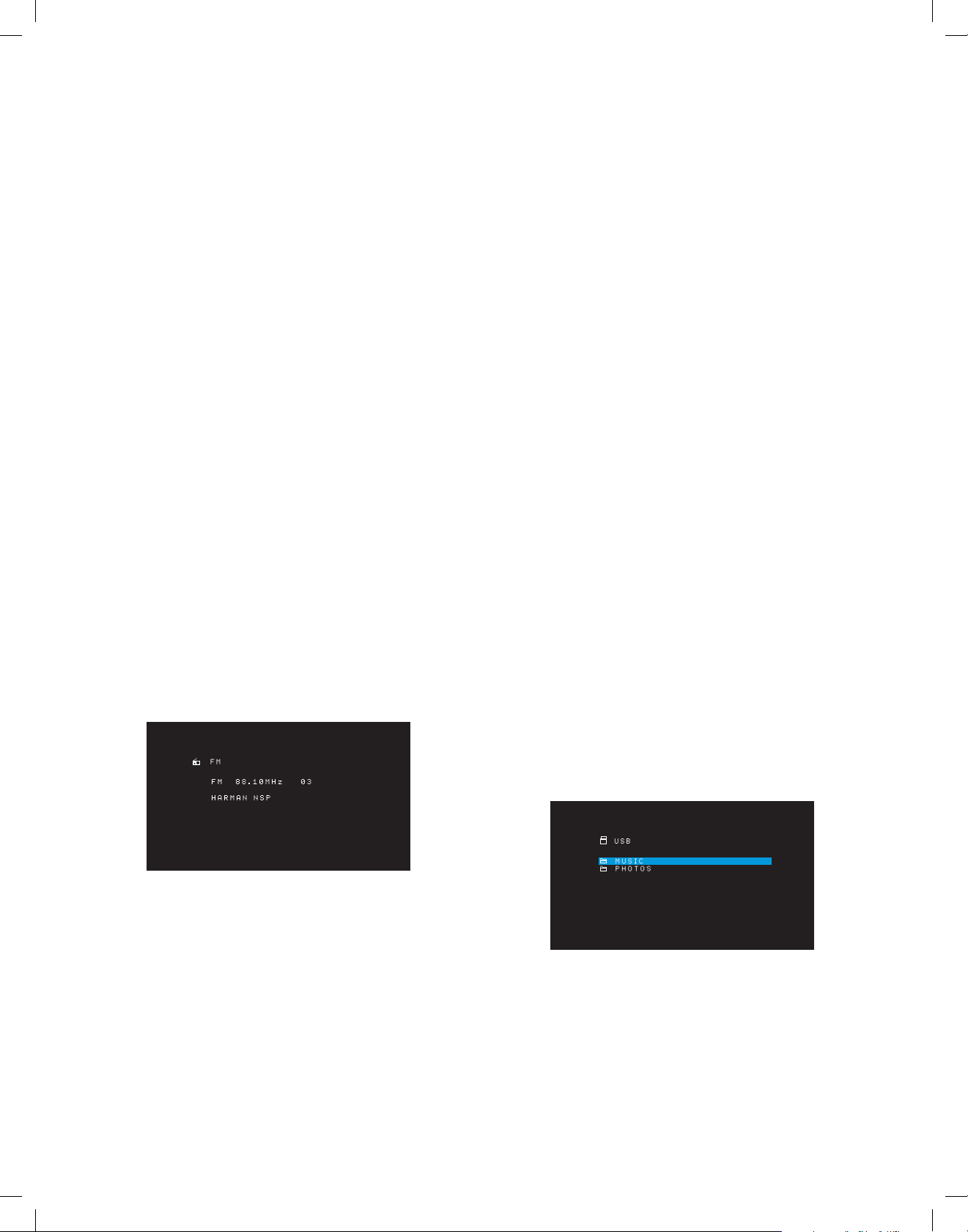
AVR
Operating Your AVR
HARMAN NSP: A HARMAN proprietary technology, NSP uses sophisticated digital
processing to deliver a true natural sounding three-dimensional listening experience
from conventional 2-channel stereo sources like CDs and stereo broadcasts. While
preserving the recording’s original timbre and spatial balance, HARMAN NSP creates a
simulated listening space that automatically adjusts to suit the type of program you are
listening to.
The following adjustments are available:
• Stage Width: This adjustment allows you to widen or narrow the width of the apparent
listening space in front of you. For example, a higher setting would be appropriate for
a recording of an orchestra playing in a concert hall, while a lower setting would be
more appropriate for a recording of a singer playing an acoustic guitar.
• Stage Depth: This adjustment lets you control the total size of the apparent listening
space. A higher setting would approximate the acoustic qualities of larger listening
spaces, such as concert halls and arenas, while a lower setting would approximate
the acoustic qualities of smaller listening spaces like small clubs or coffee houses.
Movie: Select from the following when you want a surround mode for movie playback:
DTS Neo:6 Cinema or Dolby Pro Logic II (IIx or IIz when seven main speakers are present)
in the AVR 1710S/AVR 171S.
Music: Select from the following when you want a surround mode for music playback:
DTS Neo:6 Music or Dolby Pro Logic II (IIx or IIz when seven main speakers are present
in the AVR 1710S/AVR 171S). The Dolby Pro Logic II/IIx/IIz Music mode allows access to
a submenu with some additional settings. See Audio Processing and Surround Sound, on
page 29, for more information.
Game: Dolby Pro Logic II (IIx/IIz when seven main speakers are present) Game is available
for video game playback..
After you have made your selection, press the Back/Exit button.
You can also change surround mode categories by repeatedly pressing the Surround
Mode button on either the remote or the front panel.
• You can change surround modes within surround mode categories by pressing the
Surround Mode Select buttons on the front panel.
See Audio Processing and Surround Sound, on page 29, for more information on surround
modes.
Listening to FM and AM Radio
Select the Radio source. A screen similar to the one in the illustration below will appear.
Preset Stations
You can store a total of 30 stations (AM and FM combined) as presets. When you want to
save the currently tuned station as a preset, press the remote’s Memory button. Use the
Number buttons to enter the desired preset number.
To tune to a preset station:
• Press the Left/Right buttons.
• Press the remote’s Preset Scan button. The AVR will tune to each preset station
in order for five seconds. When the desired preset is tuned, press the Preset Scan
button again.
• Enter the preset number using the Number buttons. For presets 10 through 30, press
0 before the preset number. For example, to enter preset 21, press 0-2-1.
Auto Store is an alternate method for storing presets automatically. When you select Auto
Store, your AVR will scan for any frequencies with good signal and save them as presets
automatically. To use Auto Store:
• In either FM or AM source, press the Info/Option button on the AVR’s remote
control.
• Press OK to select “Auto Store.”
• Highlight “Yes” and press “OK.”
Your AVR may take several minutes to complete the Auto Store process. Note that
performing Auto Store will erase all currently saved preset station.
Listening to Media on a USB Device
Your AVR is compatible with MP3 and WMA media.
MP3 compatibility: Mono or stereo, contstant bit rates (CBR) from 8kbps to 320kbps,
variable bit rates (VBR) from lowest to highest quality, with sample rates from 8kHz –
48kHz.
WMA compatibility: Ver. 9.2 basic, stereo CBR with 32kHz – 48kHz sampling rate and
40kbps – 192kbps bit rate, mono CBR with 8kHz – 16kHz sampling rate and 5kbps –
16kbps bit rate, VBR Pass Encoding and Quality Encoding 10 – 98, 44kHz and 48kHz
sampling rate.
No other types of media are supported.
Playing files on a USB device
1. Insert the USB drive into the AVR’s front-panel USB port.
IMPORTANT: Do not connect a personal computer or peripheral to the USB port. USB
hubs and multi-card readers are not supported.
2. Press the USB source selector button on the remote until the front-panel display’s
“USB” as the source. The USB screen will appear.
Use the Up/Down buttons or the Remote’s Channel buttons to tune a station as displayed
on the front panel and on-screen display.
The AVR defaults to automatic tuning, meaning each press of the Up/Down buttons scans
up or down the frequency band until a station with acceptable signal strength is found.
To switch to manual tuning, in which each press of the Up/Down buttons steps through
a single tuning frequency increment, press the Tuning Mode button on the front panel or
press and hold the OK button on the remote control for more than 3 seconds. Each press
of the button toggles between automatic and manual tuning modes.
Once you have tuned an FM station, toggling the Mode setting also switches the radio
between stereo and monaural reception. (Mono reception may improve reception of
weaker stations.) Note that some surround modes are not available with monaural
reception.
26
TR00306_AVR_OM_161S and 171S_EMEA_B.indb 26 26/05/15 2:29 pm
3. Select a folder and press the OK button. The AVR will list all compatible audio files.
Page 27
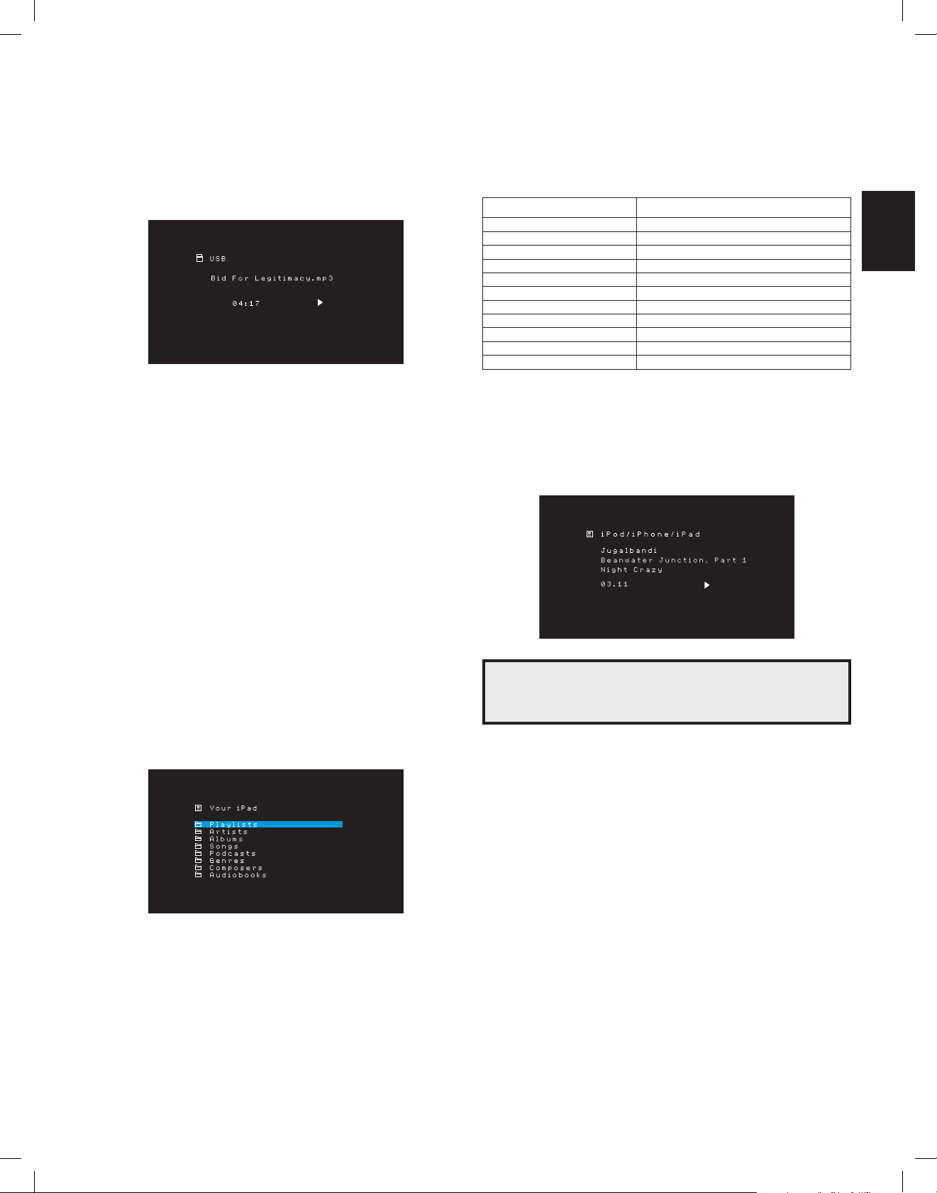
AVR
ENGLISH
Operating Your AVR
4. Select a file to begin playback. The USB play screen will appear. Any ID3 information
will be displayed, along with the track’s elapsed/current time and icons indicating the
current playback status.
NOTES:
• To skip to the next track, press the Right button; to skip to the beginning of the
current track, press the Left button once; to skip to the beginning of the previous
track, press the Left button twice (or the Left button once if the track’s elapsed time
is less than 5 seconds.)
• You can use the Transport Control buttons to control playback (skipping to the
previous or next track, searching at high speed forward or backward within a track,
playing a file, pausing playback or stopping playback).
• To repeat a file or folder, press the Option/Info Button and select the Repeat option.
Each press of the Left or Right buttons will change the setting from Off (no repeat) to
repeat One (file) to repeat All (files at the current directory level of the drive). Repeat
All will always be activated when Shuffle Music playback is turned on.
• To play the audio tracks in random order, press the Options/Info button and
select Shuffle. Each press of the Shuffle turns the setting on or off. The AVR will
automatically repeat the tracks until playback is stopped manually.
• To collapse a folder or return to the previous menu level, press the Back/Exit button.
The table below summarizes the controls available during normal playback via the USB
port.
iPod or iPhone Function Remote Control Button
Play Play
Pause Pause
Menu OSD/Menu
Back/Exit Back/Exit or Left Arrow
Select OK or Right Arrow
Scroll Reverse Up Arrow
Scroll Forward Down Arrow
Forward Search Forward Search
Reverse Search Reverse Search
Next Track Skip Forward or Right Arrow
Previous Track Skip Backward or Left Arrow
While scrolling, hold the button to scroll faster.
While a selection is playing, the song title, and play mode icon will appear on the front-
panel display.
If the AVR is connected to your TV, an iPod screen will appear and display the
play mode icon, song title, artist and album. If random or repeat play has been
programmed, an icon will appear.
Listening to an iPod/iPhone/iPad Device
When an iPod, iPhone or iPad device is connected to the AVR’s front-panel USB port,
you may play audio files through your high-quality audio system, operate the iPod,
iPad or iPhone using the AVR remote or the AVR’s front-panel controls, view navigation
messages on the AVR’s front panel or a connected video display and charge the iPod,
iPad or iPhone. For the latest compatibility information, please see our Web site: www.
harmankardon.com.
Press the USB source selector button on the remote until the front-panel displays “iPod”
as the source. The iPod screen will appear.
CAUTION: We strongly recommend that you use the screen saver built into
your video display to avoid possible damage from “burn-in” that may occur
with plasma and CRT displays when a still image, such as a menu screen,
remains on the display for an extended period of time.
Press the Option/Info button to view the iPod options menu:
Repeat: Select this setting to repeat a track or all tracks in the current album or playlist.
Each press of the OK button switches the setting: repeat Off, repeat One or repeat All.
Shuffle: Select this setting to play all the available songs in random order. Each press
of the OK button switches the setting: shuffle by Song, shuffle by Album, or Off to end
shuffle playback.
NOTE: The iTunes application allows you to exempt some tracks from Shuffle mode. The
AVR cannot override this setting.
Listening to Media via AirPlay (AVR 1710S/AVR 171S only)
If you have joined an AVR 1710S/AVR 171S to your home network you can stream audio
to it via AirPlay from compatible Apple devices with iOS 4.2 or newer and computers
that have iTunes 10.1 or newer that are joined on the same network. See Connect to
Your Home Network, on page 18, for information about connecting to your network, and
Set Up the Network, on page 24 for information about joining your network.
27
TR00306_AVR_OM_161S and 171S_EMEA_B.indb 27 26/05/15 2:29 pm
Page 28
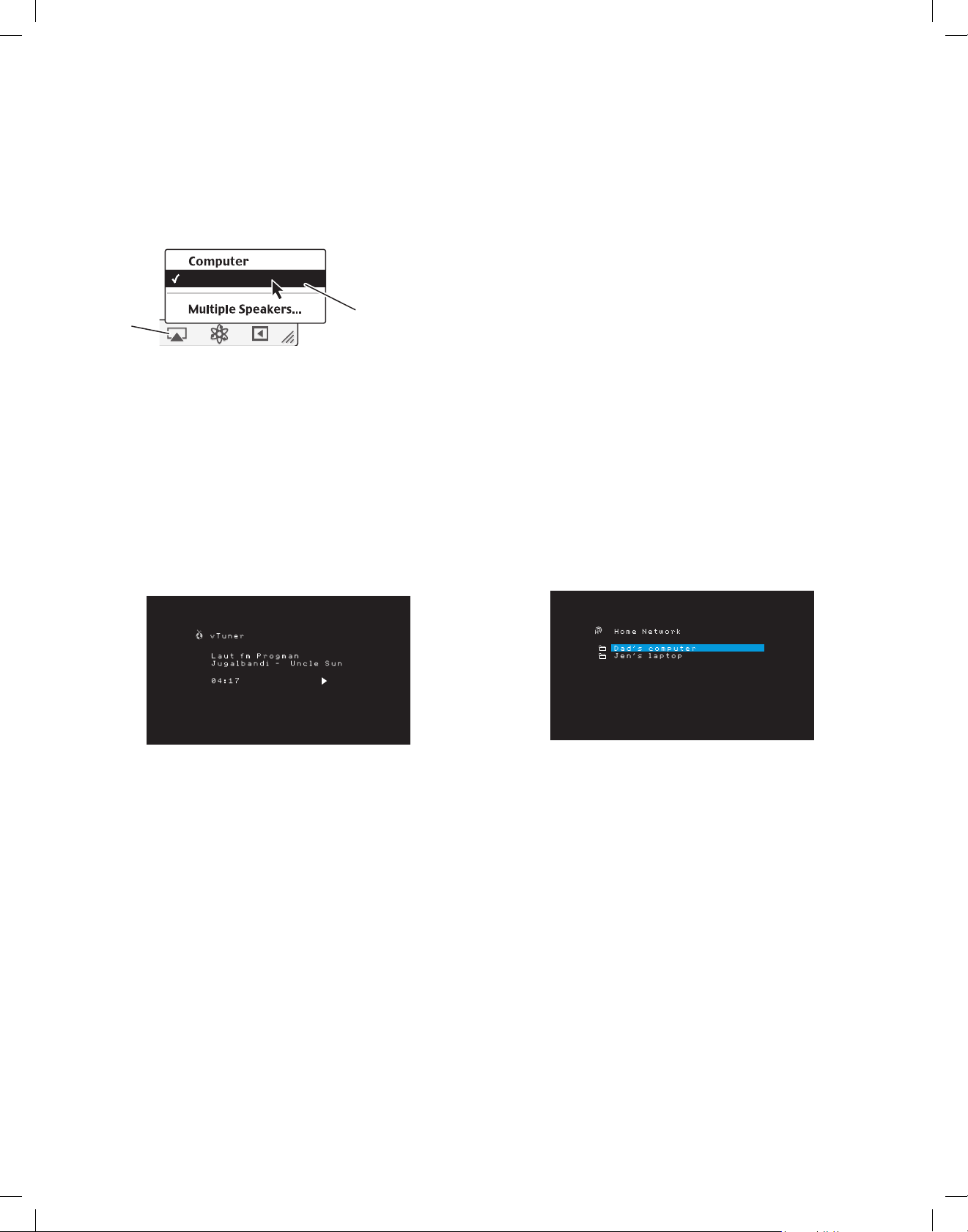
AVR
HK AVR
Operating Your AVR
To initiate AirPlay streaming to the AVR:
• To initiate AirPlay streaming from a computer with iTunes, launch iTunes, click on
the AirPlay button that appears at the bottom of the computer’s iTunes window, and
select “HK AVR” in the pop-up list that appears.
AirPlay
Button
• To initiate AirPlay streaming from an iPod, iPhone or iPad device, tap the AirPlay button
on the device’s screen and select “HK AVR171S_1710S” in the speakerselection list
that appears.
The AirPlay audio stream will break in (the OSD will display an “AirPlay activated”
message) and interrupt the source that is currently playing through the AVR. If the AVR is
in the Sleep mode, it will turn on and begin playing the AirPlay audio stream. The music
playback screen will appear on the OSD.
Use the remote’s Transport Control buttons to control playback.
Select
“HK AVR171S_1710S”
From Pop-Up List
Listening to vTuner (Internet Radio)
Your AVR’s Network connection brings you a world of MP3- and WMA-format streams via
the Internet. After you have successfully connected to your home network as described in
Connect to Your Home Network, on page 18, and set up the network as described in Set
Up the Network, on page 24, press the Network Source Selector button on the remote.
Each press toggles between the Network and vTuner screens.
Listening to Media via Your Home Network
Your AVR can access MP3 and WMA audio media that is stored on other DLNA-compatible
devices that are connected to the same network as your AVR.
MP3 compatibility: Mono or stereo, contstant bit rates (CBR) from 8kbps to 320kbps,
variable bit rates (VBR) from lowest to highest quality, with sample rates from 8kHz –
48kHz.
WMA compatibility: Ver. 9.2 basic, stereo CBR with 32kHz – 48kHz sampling rate and
40kbps – 192kbps bit rate, mono CBR with 8kHz – 16kHz sampling rate and 5kbps –
16kbps bit rate, VBR Pass Encoding and Quality Encoding 10 – 98, 44kHz and 48kHz
sampling rate.
Before you can access files located on other devices via the network, each device
must first give permission to share files with the AVR:
To share media on PCs:
1. Open Windows Media Player.
2. Open the Library menu and select Media Sharing. The Media Sharing window will
appear.
3. Check the “Share My Media” box. An icon for the AVR will appear in the window.
4. Select the AVR icon, select “Allow,” then select “OK.”
The computer’s WMA and MP3 media should now be available to the AVR.
To share media on other types of computers, operating systems or media software:
Check the instructions for the computer, operating system or media player.
To listen to shared media, press the Network Source Selector button. (If vTuner appears
as the source, press the button a second time to switch from the Internet Radio source to
the Network source.) The Home Network screen will appear.
With the vTuner screen (above) displayed, the AVR will automatically connect to the
Internet via the www.radioharmankardon.com portal. To select a stream use the Up/
Down buttons to search by category.
NOTE: The categories displayed vary by region.
To create a Favourites list, log onto www.radioharmankardon.com from your computer.
Enter your either you AVR’s MAC address as its ID # (the MAC address is on the Network
Settings screen in the System Settings menu - AVR 171S/AVR 1710S only) or your AVR’s
vTuner ID # (the vTuner ID # is found on the Help page on the vTuner main menu - AVR
161S/AVR 1610S only) and create an account. Favourites that you select on the Web site
will be available on the AVR.
Navigation is similar to other menus. Scroll to the desired item and press the OK button to
select it. To return to the previous menu level (or to clear the top-level menu from view),
press the Back/Exit button or the Left button.
The AVR is not able to connect to streams that require site registration or other interaction
prior to playing the stream. If the AVR cannot connect to the stream, a “Network Error”
message will appear briefly, and the Internet Radio screen will remain essentially blank.
28
The screen will list by name all devices on the network that allow sharing. Use the Up/
Down and OK buttons to browse the content stored in the device’s media player library.
Scroll to the desired item and press the OK button to select it. To return to the previous
menu level (or to clear the menu from view from the top level), press the Back/Exit
button.
NOTE: Although video content may appear in the menu, the AVR does not support video
playback from the network connection.
TR00306_AVR_OM_161S and 171S_EMEA_B.indb 28 26/05/15 2:29 pm
Page 29
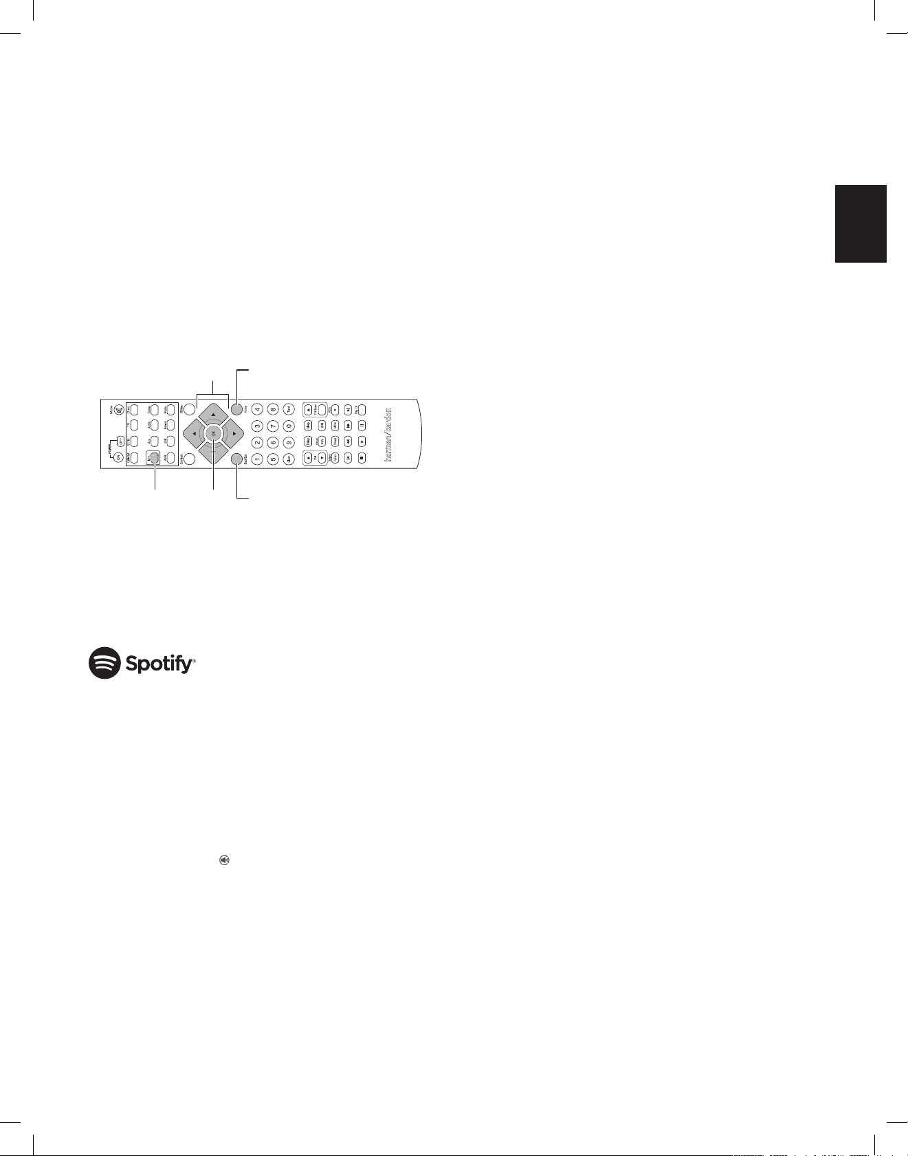
AVR
ENGLISH
Operating Your AVR and
Advanced Functions
Playing Media from a Roku Streaming Stick
When you connect a Roku Streaming Stick to the AVR’s MHL/HDMI input and join it
with your home Wi-Fi network, you can use the AVR’s remote to search for and control
streaming media. NOTE: Your home network must be Wi-Fi for you to be able to use the
Roku Streaming Stick with your AVR.
1. After connecting the Roku Streaming Stick to the AVR’s MHL/HDMI input, select the
AVR’s MHL source. The Roku Streaming Stick’s video output should be displayed on
your TV.
2. Follow the Roku instructions for joining the Roku Streaming Stick with your Wi-Fi
network, using the Roku remote.
3. Once the Roku Streaming Stick is joined with your Wi-Fi network, the AVR remote
buttons shown below will perform the same functions as their counterparts on the
Roku remote:
MHL Source
Button
Menu
Navigation
Menu Item
Selection
Home Menu
Previous
Menu
Listening to Media via Spotify Connect
Your Harman Kardon AVR and Spotify control device need to be on the same wi-fi network
to work.
From the Spotify App on your mobile device tap on the Now Playing bar to reveal extra
controls, and select the Speaker icon. From the Connect screen, just choose your AVR
models from the list as a destination device and it’ll start playing. Adjust the volume
directly from the app using the volume bar from the Connect screen.
Using This Device With Spotify Connect
Spotify lets you listen to millions of songs – the artists you love, the latest hits and
discoveries just for you.
If you are a Spotify user, you can control this device using your Spotify app.
Step 1 Connect your device to the same wifi network as your phone, tablet or PC
running the Spotify app.
Step 2 Open the Spotify app, and play any song.
Step 3 Tap the song image in the bottom left of the screen.
Step 4 Tap the Connect icon
Step 5 Pick your speaker from the list.
For information on how to set up and use Spotify Connect please visit www.spotify.
com/connect
Licenses
The Spotify Software is subject to third party licenses found here : www.spotify.com/
connect/third--party- -licenses.
Advanced Functions
Much of the adjusting and configuration your AVR requires is handled automatically, with
little intervention required on your part. You can also customize your AVR to suit your
system and your tastes. In this section we will describe some of the more advanced
adjustments available to you.
Audio Processing and Surround Sound
Audio signals can be encoded in a variety of formats that can affect not only the quality
of the sound but the number of speaker channels and the surround mode. You may also
manually select a different surround mode, when available.
Analog Audio Signals
Analog audio signals usually consist of two channels – left and right. Your AVR is able
to process two-channel audio signals to produce multichannel surround sound, even
when no surround sound has been encoded in the recording. Among the available
modes are the Dolby Pro Logic II/IIx/IIz, Virtual Speaker, DTS Neo:6, HARMAN NSP,
5 CH and 7 CH Stereo modes. To select one of these modes, press the Surround
Modes button.
Digital Audio Signals
Digital audio signals offer greater flexibility and capacity than analog signals, and
allow the encoding of discrete channel information directly into the signal. The result is
improved sound quality and startling directionality, since each channel’s information is
transmitted discretely. High-resolution recordings sound extraordinarily distortion-free,
especially in the high frequencies.
Surround Modes
Surround-mode selection depends upon the format of the incoming audio signal as well
as your personal taste. Although there is never a time when all of the AVR’s surround
modes are available, there is usually a wide variety of modes available for a given input.
Table A12 in the Appendix, on page 47, offers a brief description of each mode and
indicates the types of incoming signals or digital bitstreams the mode may be used with.
Additional information about the Dolby and DTS modes is available on the companies’
Web sites: www.dolby.com and www.dtsonline.com.
When in doubt, check the jacket of your disc for more information on which surround
modes are available. Usually, nonessential sections of the disc, such as trailers, extra
materials or the disc menu, are available only in Dolby Digital 2.0 (two-channel) or
PCM two-channel mode. If the main title is playing and the display shows one of these
surround modes, look for an audio or language setup section in the disc’s menu. Also,
make sure your disc player’s audio output is set to the original bitstream rather than twochannel PCM. Stop play and check the player’s output setting.
Multichannel digital recordings are produced in five-channel, six-channel or sevenchannel formats, with or without a “.1” channel. The channels included in a typical
5.1-channel recording are front left, front right, center, surround left, surround right and
LFE (low-frequency effects). The LFE channel is denoted as “.1” to represent the fact that
it is limited to the low frequencies. 6.1-channel recordings add a single surround back
channel, and 7.1-channel recordings add surround back left and surround back right
channels to the 5.1-channel configuration. New formats are available in 7.1-channel
configurations. Your AVR is able to play the new audio formats, delivering a more exciting
home theater experience.
AVR 1710S/AVR 171S only: To use the 6.1- and 7.1-channel surround modes, the
surround back channels must be enabled. See Manual Speaker Setup, on page 30 for
more information.
Digital formats include Dolby Digital 2.0 (two channels only), Dolby Digital 5.1, Dolby
Digital EX (6.1), Dolby Digital Plus (7.1), Dolby TrueHD (7.1), DTS-HD High-Resolution
Audio (7.1), DTS-HD Master Audio (7.1), DTS 5.1, DTS-ES (6.1 Matrix and Discrete),
DTS 96/24 (5.1), two-channel PCM modes in 32kHz, 44.1kHz, 48kHz, 88.1kHz, 96kHz,
176.4kHz or 192kHz, and 5.1 or 7.1 multichannel PCM.
When the AVR receives a digital signal, it detects the encoding method and the number
of channels, which is displayed briefly as three numbers, separated by slashes (e.g.,
“3/2/.1”).
29
TR00306_AVR_OM_161S and 171S_EMEA_B.indb 29 26/05/15 2:29 pm
Page 30
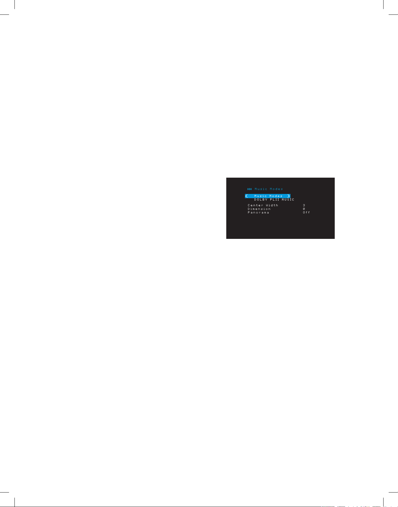
AVR
Advanced Functions
The first number indicates the number of front channels in the signal: “1” represents
a monophonic recording (usually an older program that has been digitally remastered
or, more rarely, a modern program for which the director has chosen mono as a special
effect). “2” indicates the presence of the left and right channels but no center channel.
“3” indicates that all three front channels (left, right and center) are present.
The second number indicates whether any surround channels are present: “0” indicates
that no surround information is present. “1” indicates that a matrixed surround signal is
present. “2” indicates discrete left and right surround channels. “3” is used with DTS-ES
bitstreams to represent the presence of the discrete surround back channel, in addition
to the side surround left and right channels. “4” is used with 7.1-channel digital formats
to indicate the presence of two discrete side surround channels and two discrete back
surround channels.
The third number is used for the LFE channel: “0” indicates no LFE channel. “.1” indicates
that an LFE channel is present.
The 6.1-channel signals – Dolby Digital EX and DTS-ES Matrix and Discrete – each
include a flag that signals the receiver to decode the surround back channel, indicated
as 3/2/.1 EX-ON for Dolby Digital EX materials, and 3/3/.1 ES-ON for DTS-ES materials.
Dolby Digital 2.0 signals may include a Dolby Surround flag indicating DS-ON or DS-OFF,
depending on whether the two-channel bitstream contains only stereo information or a
downmix of a multichannel program that can be decoded by the AVR’s Dolby Pro Logic
decoder. By default, these signals are played in Dolby Pro Logic IIx Movie mode.
When a PCM signal is received, the PCM message and the sampling rate (32kHz,
44.1kHz, 48kHz, 88.2kHz, 96kHz, 176.4kHz or 192kHz) will appear.
When only two channels – left and right – are present, the analog surround modes may be
used to decode the signal into multiple channels. If you would prefer a different surround
format than the native signal’s digital encoding, press the Surround Modes button to
display the Surround Modes menu (see Selecting a Surround Mode, on page 25).
The Auto Select option sets the surround mode to the native signal’s digital encoding, e.g.,
Dolby Digital, DTS, Dolby TrueHD or DTS-HD Master Audio. For two-channel materials, the
AVR defaults to the HARMAN NSP mode. If you prefer a different surround mode, select
the surround-mode category: Virtual Surround, Stereo, Movie, Music or Video Game.
Press the OK button to change the mode.
Each surround-mode category is set to a default surround mode:
• Virtual Surround: Virtual speaker.
• Stereo: 7-CH Stereo or 5-CH Stereo (depending on how many main speakers are
present in the system).
• NSP: HARMAN NSP.
• Movie: Dolby Pro Logic II Movie.
• Music: Dolby Pro Logic II Movie.
• Video Game: Dolby Pro Logic II Movie.
You may select a different mode for each category. Below is a complete list of available
surround modes. (The actual surround modes available will depend on the number of
speakers in your system.)
• Virtual Surround: Virtual speaker.
• Stereo: 2-CH Stereo, 5-CH Stereo or 7-CH Stereo (AVR 1710S/AVR 171S only).
• NSP: HARMAN NSP.
• Movie: DTS Neo:6 Cinema, Dolby Pro Logic II Movie, Dolby Pro Logic IIx Movie (AVR
1710S/AVR 171S only), Dolby Pro Logic IIz (AVR 1710S/AVR 171S only).
• Music: DTS Neo:6 Music, Dolby Pro Logic II Music, Dolby Pro Logic IIx Music (AVR
1710S/AVR 171S only), Dolby Pro Logic IIz (AVR 1710S/AVR 171S only).
• Video Game: Dolby Pro Logic II Game, Dolby Pro Logic IIx Game (AVR 1710S/AVR
171S only), Dolby Pro Logic IIz (AVR 1710S/AVR 171S only).
Once you have programmed the surround mode for each type of audio, select the line
from the Surround Modes menu to override the AVR’s automatic surround-mode selection.
The AVR will use the same surround mode the next time the source is selected.
AVR 1710S/AVR 171S only: Dolby Pro Logic IIx is available only if you have set up the
AVR’s Assigned Amp to Surround Back; Dolby Pro Logic IIz is available only if you have
set up the AVR’s Assigned Amp to Front Height. See Manual Speaker Setup, on page 30,
for more information.
PLIIz Height Gain (AVR 1710S/AVR 171S only): When you have set the Assigned Amp
to Front Height (see Manual Speaker Setup, on page 30), the PLIIz Height Gain setting will
become available. The front height channels can greatly improve the spatial experience
of a surround-sound system. Some listeners may want the depth and dimension that
height channels provide, but from a seemingly transparent experience. Other listeners
may prefer to accentuate the front height channels by using a higher volume setting.
The PLIIz Height Gain control gives you the ability to change the volume of the front height
channels to suit different programs. The control has three settings: Low (normal volume),
Mid (moderate volume increase) and High (maximum volume increase). Note that you
can also fine-tune the front height channel volume levels. See Setting Channel Output
Levels Manually, on page 32, for details.
Dolby PLII/Dolby PLIIx Music:
the Dolby Pro Logic II or IIx Music Mode in the Surround Modes menu:
Center Width: This setting affects how vocals sound through the three front speakers.
A lower number focuses the vocal information tightly on the center channel. Higher
numbers (up to 7) broaden the vocal soundstage. Use the Left/Right buttons to adjust.
Dimension: This setting affects the depth of the surround presentation, allowing you to
“move” the sound toward the front or rear of the room. The setting of “0” is a neutral
default. Setting “F-3” moves the sound toward the front of the room, while setting “R-3”
moves the sound toward the rear. Use the Left/Right buttons to adjust it.
Panorama: With the Panorama mode turned on, some of the sound from the front
speakers is moved to the surround speakers, creating an enveloping “wraparound”
effect. Each press of the OK button toggles the setting On or Off.
Please refer to Table A10 in the Appendix for more information on which surround modes
are available with different bitstreams.
Some additional settings are available when you select
Manual Speaker Setup
Your AVR is flexible and may be configured to work with most speakers and to compensate
for the acoustic characteristics of your room.
The EzSet/EQ process automatically detects the capabilities of each connected speaker
and optimizes the AVR’s performance with your speakers. If you are unable to run EzSet/
EQ calibration, or if you wish to set up your AVR for your speakers manually, use the
Speaker Setup on-screen menus.
Before beginning, place your loudspeakers as explained in the Place Your Speakers
section, on page 11, and connect them to the AVR. Consult the owner’s guide for the
speakers or the manufacturer’s Web site for their frequency-range specification. Although
you may set the AVR’s individual channel levels “by ear,” an SPL (sound-pressure level)
meter purchased at a local electronics store will provide greater accuracy.
Record your configuration settings in Tables A3 through A12 in the Appendix for easy
re-entry after a system reset or the unit has been unplugged for more than four weeks.
30
TR00306_AVR_OM_161S and 171S_EMEA_B.indb 30 26/05/15 2:29 pm
Page 31

AVR
ENGLISH
Advanced Functions
Step One – Determine Your Speakers’ Crossover Frequencies
Without using the EzSet/EQ process, the AVR can’t detect how many speakers
you’ve connected to it; nor can it determine their capabilities. Consult the technical
specifications for all of your speakers and locate the frequency response, usually given
as a range, e.g., 100Hz – 20kHz (±3dB). Write down the lowest frequency that each of
your speakers (except the subwoofer) is capable of playing (100Hz in the above example)
as the crossover in Table A3 in the Appendix. NOTE: This is not the same as the crossover
frequency listed in the speaker’s specifications.
The AVR’s bass management determines which speakers will be used to play back the
low-frequency (bass) portion of the source program. Sending the lowest notes to small
satellite speakers will result in bad sound and may even damage the speakers. The
highest notes may not be heard at all through the subwoofer.
With proper bass management, the AVR divides the source signal at a crossover frequency.
All information above that crossover frequency is played through your system’s speakers,
and all information below the crossover frequency is played through the subwoofer. This
way, each loudspeaker in your system will perform at its best, delivering a more powerful
and enjoyable sound experience.
Step Two – Measure the Speaker Distances
Ideally, all of your speakers would be placed in a circle, with the listening position at the
center. However, you may have had to place some speakers a little farther away from
the listening position than others. Because of this, sounds that are supposed to arrive
simultaneously from different speakers may blur, due to different arrival times.
Your AVR provides a Distance adjustment that compensates for these real-world speaker
placement differences.
Measure the distance from each speaker to the listening position, and write it down
in Table A4 in the Appendix. Even if all of your speakers are the same distance from
the listening position, enter your speaker distances as described in Set the Speaker
Distances, on page 32.
Step Three – Manual Speaker Setup Menu
Now you are ready to program the AVR. Sit in your usual listening position, and make the
room as quiet as possible.
With the AVR and video display turned on, press the OSD/Menu button to display the
menu system. Select the Speaker Setup menu, and then select Manual Setup.
NOTE: To save the current settings, press the Back/Exit button.
For best results, adjust the submenus in this order: Speakers, Crossover, Distance and
Output Adjust.
Speakers
This selection lets you program the correct setting for each speaker group. The settings
in this menu affect the remainder of the speaker setup process and the availability of
various surround modes at any time.
Select ON when the speakers are present in the system; select OFF for positions where
no speakers are installed. The Front Left & Right setting is always ON and may not be
disabled.
Any changes will be reflected in the total Number Of Speakers displayed at the top of
the screen.
AVR 1710S/AVR 171S only: The Assigned AMP setting includes four options:
• Surround Back: Select the Surr. Back option if your main system is a 7.1-channel
system and you are using surround back left and surround back right speakers.
• Zone 2: Select the Zone 2 option if your main system is a 5.1-channel system and
you want to use the Assigned Amp speaker outputs to power speakers in Zone 2. See
Install a Multizone System, on page 19, for more information.
• Front Height: Select the Front Height option if your main system is a 7.1-channel
system and you are using Front Height speakers with Dolby Pro Logic IIz.
• Off: Select Off if you have not connected speakers to the Assigned Amp speaker
outputs.
NOTE: When you set Assigned AMP to “Zone 2,” the speakers connected to the Assigned
Amp outputs will not be configured during the EzSet/EQ process. Configure the speakers
manually, as explained below.
When you have finished, press the Back/Exit button.
Crossover
After you return to the Speaker Setup menu, navigate to the Crossover line and press the
OK button to display the Crossover menu.
If you have already run the EzSet/EQ process as explained in Configure the AVR for Your
Speakers, on page 22, the AVR saved the results. To fine-tune the EzSet/EQ results, or
to configure the AVR from scratch, select Manual Setup. The Manual Setup screen will
appear.
The AVR will display only those speaker groups you set to On in the Number of Speakers
menu.
Refer to Table A3 to see the crossover frequencies that you wrote down for your
speakers.
31
TR00306_AVR_OM_161S and 171S_EMEA_B.indb 31 26/05/15 2:29 pm
Page 32

AVR
Troubleshooting
Advanced Functions
For each speaker group, select one of these eight crossover frequencies: Large, 40Hz,
50Hz, 60Hz, 70Hz, 80Hz, 90Hz, 100Hz, 110Hz, 120Hz, 140Hz, 150Hz, 160Hz, 180Hz
or 200Hz. If the speaker’s crossover frequency is below 40Hz, select the first option,
“Large.” This setting doesn’t refer to the speaker’s physical size but to its frequency
response, which is also called “full range.”
NOTE: If you have Room EQ set to On, the crossover frequencies have been automatically
set by the AVR and cannot be adjusted.
Write down the settings in Table A6 in the Appendix.
When you have finished entering the settings, press the Back/Exit button to return to the
Manual Setup menu.
Select the “Speakers” menu again and note the Subwoofer setting: This setting depends
upon the Crossover setting you selected for the front left and right speakers.
• If you set the front speakers to a numeric crossover frequency, the subwoofer
setting will always be SUB. All low-frequency information will always be sent to the
subwoofer. If you don’t have a subwoofer, either upgrade to full-range front left and
right speakers or add a subwoofer at the earliest opportunity.
• If you set the front left/right speakers to LARGE, select one of the three following
settings for the subwoofer:
L/R+LFE: This setting sends all low-frequency information to the subwoofer,
including a) information that would normally be played through the front left and
right speakers and b) the special low-frequency effects (LFE) channel information.
OFF: Select this setting when no subwoofer is in use. All low-frequency information
will be sent to the front left and right speakers.
LFE: This setting plays low-frequency information contained in the left and right
program channels through the front left and right speakers, and directs only the
LFE-channel information to the subwoofer.
Distance
As described above in Step Two, when you measured the distances from each of your
speakers to the listening position, your AVR provides an adjustment that compensates
for the different distances so that the sound from each speaker will reach the listening
position at the proper time. This process will improve the clarity and detail of the sound.
On the Manual Setup menu, move the cursor to the Distance line and press the OK button
to display the Adjust Speaker Distance menu.
Enter the distance from each speaker to the listening position that you measured in Step
Two and recorded in Table A4 in the Appendix (see page 39). Select a speaker, then use
the Left/Right buttons to change the measurement. You can enter distances between 0
and 30 feet (9.1m). The default distance for all speakers is 10 feet (3m).
The default unit of measurement is feet. To change the unit to meters, select the Unit of
Measure line and press the Left or Right button to change the setting.
NOTE: If you set the Assigned AMP channels to Zone 2, you will not be able to adjust
their delay settings.
Step Four – Setting Channel Output Levels Manually
For a conventional stereo receiver, a simple balance control adjusts the stereo imaging
by varying the relative loudness of the left and right channels. In a home theater system
with up to seven main channels plus up to two subwoofers, achieving proper imaging
becomes both more critical and more complex. The goal is to ensure that each channel
is heard at the listening position with equal loudness (when signals of equal loudness
are played through them).
Your AVR’s EzSet/EQ calibration can handle this critical task for you simply and
automatically. However, the Output Adjust menu allows you to calibrate the levels
manually, either using the system’s built-in test tone or while playing source material.
From the Manual Setup menu select Output Adjust to display the speaker volume
adjustment menu.
All of the system’s speakers will appear with their current level settings. You can adjust
each speaker’s level between –10dB and +10dB in 1dB increments.
While making adjustments, you can measure the channel levels in one of these ways:
• Preferably, use a handheld SPL meter set to the C-weighting, slow scale. Adjust each
speaker so that the meter reads 75dB when the AVR’s built-in test noise is playing.
• By ear. Adjust the levels so that the test tone sounds equally loud to you when it plays
through each speaker.
To set your levels using the AVR’s internal test tone, select the menu’s Test Tone line and
use the Left/Right buttons to turn the test tone on. Then select the Test Tone SEQ line to
select between Auto and Manual:
Auto: The test tone will automatically circulate to all speakers, as indicated by the
highlight bar. Use the Left/Right buttons to adjust the level for any speaker when the test
tone is paused there. Use the Up/Down buttons to move the highlight bar to another line,
and the test tone will follow the bar. To stop the test tone, use the Up/Down buttons to
move the cursor out of the screen’s speaker listings area.
Manual: The test tone will stay on the selected speaker until you use the Up/Down
buttons to move it to another speaker. Use the Left/Right buttons to adjust the level for
the speaker through which the test tone is playing.
If you are using an external source to set your output levels, set Test Tone to Off, use the
Up/Down buttons to navigate to each speaker, and use the Left/Right buttons to adjust
the speaker’s level while the source plays.
NOTE: If you are using a handheld SPL meter with external source material, such as a
test disc or an audio selection, play it and adjust the AVR’s master volume control until
the meter measures 75dB. Then adjust the individual speaker levels.
Output Reset: To reset all levels to their factory defaults of 0dB, scroll down to this line
and press the OK button.
When you have finished adjusting the speaker levels, record the settings in Table A3 in
the Appendix. Then press the Back/Exit Button.
32
TR00306_AVR_OM_161S and 171S_EMEA_B.indb 32 26/05/15 2:29 pm
Page 33

AVR
ENGLISH
Advanced Functions
Notes on Setting Speaker Volumes in Home Theater Systems:
While setting your system’s individual speaker volume levels is ultimately up to your
personal taste, here are some ideas you may find helpful:
• For films and video-music programs, your overall goal should be to create an
enveloping, realistic sound field that draws you into the film or music program
without drawing your attention away from the action on the screen.
• For multichannel music recordings, some music producers will create a sound field
that places the musicians all around you; others will create a sound field that places
the musicians in front of you, with more subtle ambience in the surround speakers
(as you would experience in a concert hall).
• In most 5.1-channel and 7.1-channel film soundtracks, the surround speakers are
not intended to be as loud or as active as the front speakers. Adjusting the surround
speakers so they are always as loud as the front speakers could make dialogue
difficult to understand and will make some sound effects sound unrealistically loud.
Notes on Setting Subwoofer Volume:
• Sometimes the ideal subwoofer volume setting for music is too loud for films, while
the ideal setting for films is too quiet for music. When setting the subwoofer volume,
listen to both music and films with strong bass content and find a “middle ground”
volume level that works for both.
• If your subwoofer always seems too loud or too quiet, you may want to place it in
a different location. Placing the subwoofer in a corner will always tend to increase
its bass output, while placing it away from any walls or corners will always tend to
reduce its bass output.
AVR 1710S/AVR 171S only: Listening in Zone 2
With the multizone system in use, you may enjoy an exciting 5.1-channel home theater
presentation in the main listening area, while others listen to an entirely different source in
another room. See Install a Multizone System, on page 19, for installation information.
You set up and activate the AVR’s multizone system from the on-screen Zone 2 menu.
Press the OSD/Menu button, and navigate to the Zone 2 line. Press the OK button to
display the Zone 2 menu.
Notes about listening in Zone 2:
• Although you can listen to iPod or USB as a source in Zone 2, you cannot begin
iPod or USB playback from within Zone 2. You must initially select iPod or USB as a
source in Zone 1 and begin playback of a track or playlist from there. Then you can
select iPod as the Zone 2 source and control playback from within Zone 2 even if you
switch Zone 1 to a different source.
• Only one of the AVR’s internal sources (iPod, USB, vTuner, Network, AirPlay, DLNA
DMR) can be active at a time across both zones. For example, if you are listening
to vTuner as the source in Zone 1 and switch the source in Zone 2 to USB, it will
switch the source in Zone 1 to USB(and vice versa). To listen to different sources in
Zone 1 and Zone 2 at the same time, at least one source must be one of the AVR’s
configurable external sources (Cable/Sat, Disc, STB or TV) that is connected to one
of the AVR’s analog audio inputs, or one of the AVR’s terrestrial radio sources (FM
or AM).
Volume: Highlight this line, and use the Left/Right buttons to control the volume in Zone
2.
Assigned AMP: This line lets you assign the Assigned AMP channels to “Zone 2” for
multizone operation (see Number of Speakers, on page 31). When this line is set to Zone
2, you may configure the main listening room for only up to 5.1 channels.
To use the remote to control the sound in Zone 2, press the remote’s Zone 2 button. The
volume, mute and source select buttons will control the sound in Zone 2 and the Zone 2
button will illuminate whenever you press a button to indicate that the remote is in the
Zone 2 control mode. Press the Zone 2 button again to return the remote to the main
listening area control mode.
Status: This line lets you turn Zone 2 on or off.
Source: This line lets you select the source input for Zone 2. You may select a different
source from the one currently operating in the main listening area. However, if the same
source has been selected for both the main listening area and Zone 2, listeners in both
areas will hear the same content.
Only analog audio sources are available to Zone 2. To hear digital devices such as a CD
player in Zone 2, follow these steps:
1. In addition to making a digital audio connection, connect the source device’s analog
audio outputs to the AVR. Make a note in Table A5 on page 39 to record which set of
analog inputs you used.
2. Use the AVR’s front-panel Audio Input button to select the analog audio input. (Leave
the Audio setting for the source device in the Source Setup menu set to the digital
input.)
33
TR00306_AVR_OM_161S and 171S_EMEA_B.indb 33 26/05/15 2:29 pm
Page 34

AVR
Appendix
ENGLISH
AVR
Troubleshooting
Symptom Cause Solution
Unit does not function • No AC power • Ensure that the power cord is plugged into a live AC
power outlet
• Check if the AC outlet is switch-controlled
Front-panel display lights, but there’s no sound or picture • Intermittent input connection
• Mute is on
• Volume control is turned down
• Secure all input and speaker connections
• Press Mute button
• Turn up Volume control
No sound from any speaker •
is in protection mode due to possible short
circuit
•
is in protection mode due to internal
problems
• Check all speaker wires at speaker and AVR
connections for crossed wires
• Contact your local Harman Kardon service center
No sound from center or surround speakers • Incorrect surround mode
• Program material is monophonic
• Incorrect speaker
• Program material is stereo
• Select a surround mode other than stereo
• Mono programs contain no surround information
• Check the speaker in the setup menu
• The surround decoder may not create center- or
surround-channel information from nonencoded
programs
Unit does not respond to remote control commands • Weak batteries in remote
• Remote sensor is obscured
• Change batteries in remote
• Ensure that the AVR’s front-panel remote sensor is in
the line of sight of the remote
Intermittent buzzing in tuner • Local interference • Move the AVR or antenna away from computers,
fluorescent lights, motors or other electrical appliances
(AVR 1710S/AVR 171S only): Surround-back speaker
settings cannot be accessed, and the test tone does not
play through the surround back speakers
• Multi-zone operation has been selected/Assigned AMP
channels have been assigned to Zone 2
• Use the Speaker Setup menu to reassign the Assigned
AMP to the surround back left and right channels
Unable to activate remote control Programming mode • Source Selector button is not held for at least 3
seconds
• Be sure to hold the Source Selector button for at least
3 seconds
Remote buttons light, but AVR does not respond • Remote is in Zone 2 mode • Press Zone 2 button (button will not illuminate when
remote is in Zone 1 control mode).
Unable to establish network connection • AVR network programming requires rebooting • Cycle the AVR into the Off mode, and then turn it on
again
Additional information on troubleshooting possible problems with your AVR and installation-related issues may be found in the list of “Frequently Asked Questions,” which is located
in the Product Support section of our Web site: www.harmankardon.com
Troubleshooting
System Settings
System Settings
The AVR’s System Settings menu lets you customize in what way many of the AVR’s
features operate. Press the OSD/Menu button and navigate to the System line. Press the
OK button to display the System Settings menu.
Sleep Timer
The sleep timer sets the AVR to play for up to 90 minutes and then turn off
automatically.
Press the Sleep button on the remote, and the time until turn-off will be displayed.
Each additional press of the Sleep button increases the play time by 10 minutes, with a
maximum of 90 minutes. The SLEEP OFF setting disables the sleep timer.
When the sleep timer has been set, the front-panel display will automatically dim to half
brightness.
If you press the Sleep button after the timer has been set, the remaining play time will be
displayed. Press the Sleep button again to change the play time.
The front-panel display will count down during the final 10 seconds before going to Sleep
mode. Pressing any button during this countdown will cancel the process and disable
the Sleep timer.
Processor Reset
Panel Timeout: This setting allows you to set the AVR’s front-panel display to automatically
turn off after remaining on for a predetermined time (3 – 10 seconds) each time you use
a control. Set this to “Off” to have the display remain on continually.
Auto Power Off: This setting allows you to set the AVR to automatically switch to the
Off mode after being in the Sleep mode for a predetermined time (1 – 8 hours). See
Power Indicator/Power Button, on page 4, for more information. It also allows the AVR
to automatically switch to the Sleep mode after being on for the predetermined amount
of time. Note that it will not transition to Sleep mode this way if the active source has
one of the Digital Audio Connectors selected as the Audio Input. See Source Setup, on
page 23, for more information.
Menu Timeout: This setting allows you to set the amount of time (20 – 50 seconds) a
menu screen will remain on after the last adjustment. Set this to “Off” to have the menus
remain on continually until you press the OSD/Menu button.
Status Message: When the AVR is turned on, the volume is adjusted, the source is
changed or a change in the input signal is detected, a status message will be displayed
on the TV screen. Select how long the message remains visible, from 2 to 10 seconds,
with a default of 3 seconds. Select “Off” if you do not wish to see the status messages on
the TV screen (they will still appear on the AVR’s front-panel display).
Volume Default and Default Volume Setting: These two settings are used together to
program the volume level when you turn on the AVR. Set Volume Default to On, and then
set the Default Volume Setting to the desired turn-on volume. When Volume Default is set
to Off, the AVR will turn on at the last-used volume setting from the previous listening
session.
HDMI Audio to TV: This setting determines whether HDMI audio signals are passed
through the HDMI Monitor Out connector to the video display. In normal operation, leave
this setting at Off, as audio will be played through the AVR. To use the TV by itself, without
the home theater system, turn this setting to On.
HDMI Link: This setting allows the communication of control information among the
HDMI devices in your system. Turn this setting to On to allow control communication
between the HDMI devices; turn the setting to Off to forbid control communication.
Software Update: If a software upgrade is released for your AVR, installation instructions
will be available in the Product Support section of the Web site or from Harman Kardon
customer service. At that time, you may use this submenu to install the upgrade
software.
IMPORTANT: During a software upgrade, do not power off the AVR or use any of its
controls. Doing so could permanently damage the AVR.
If the AVR behaves erratically after a power surge, unplug the AC power cord for at least
3 minutes. Plug the cord back in and turn the AVR on. If this procedure doesn’t help, reset
the AVR’s processor as described below.
NOTE: A processor reset erases all user configurations, including speaker and level
settings and tuner presets. After a reset, reenter all of these settings from your entries in
the Appendix worksheets.
To reset the AVR’s processor:
1. Press the front-panel Power Button for more than three seconds to turn the AVR off (the
Power Indicator will turn amber).
2. Press and hold the front-panel Surround Mode Category button for at least 5 seconds
until the RESET message appears on the front-panel display.
NOTE: After performing a processor reset, wait at least 1 minute before pressing any
Source Selector buttons.
If the AVR does not function correctly after a processor reset, contact an authorized
Harman Kardon service center for assistance. Authorized service centers may be located
by visiting our Web site at www.harmankardon.com.
34
TR00306_AVR_OM_161S and 171S_EMEA_B.indb 34 26/05/15 2:29 pm
Page 35

AVR
ENGLISH
ENGLISH
AVR
Troubleshooting
Troubleshooting
Symptom Cause Solution
Troubleshooting
Unit does not function • No AC power • Ensure that the power cord is plugged into a live AC
Front-panel display lights, but there’s no sound or picture • Intermittent input connection
No sound from any speaker •
No sound from center or surround speakers • Incorrect surround mode
Unit does not respond to remote control commands • Weak batteries in remote
Intermittent buzzing in tuner • Local interference • Move the AVR or antenna away from computers,
• Mute is on
• Volume control is turned down
is in protection mode due to possible short
circuit
•
• Program material is monophonic
• Incorrect speaker
• Program material is stereo
• Remote sensor is obscured
is in protection mode due to internal
problems
power outlet
• Check if the AC outlet is switch-controlled
• Secure all input and speaker connections
• Press Mute button
• Turn up Volume control
• Check all speaker wires at speaker and AVR
connections for crossed wires
• Contact your local Harman Kardon service center
• Select a surround mode other than stereo
• Mono programs contain no surround information
• Check the speaker in the setup menu
• The surround decoder may not create center- or
surround-channel information from nonencoded
programs
• Change batteries in remote
• Ensure that the AVR’s front-panel remote sensor is in
the line of sight of the remote
fluorescent lights, motors or other electrical appliances
(AVR 1710S/AVR 171S only): Surround-back speaker
settings cannot be accessed, and the test tone does not
play through the surround back speakers
Unable to activate remote control Programming mode • Source Selector button is not held for at least 3
Remote buttons light, but AVR does not respond • Remote is in Zone 2 mode • Press Zone 2 button (button will not illuminate when
Unable to establish network connection • AVR network programming requires rebooting • Cycle the AVR into the Off mode, and then turn it on
Additional information on troubleshooting possible problems with your AVR and installation-related issues may be found in the list of “Frequently Asked Questions,” which is located
in the Product Support section of our Web site: www.harmankardon.com
• Multi-zone operation has been selected/Assigned AMP
channels have been assigned to Zone 2
seconds
• Use the Speaker Setup menu to reassign the Assigned
AMP to the surround back left and right channels
• Be sure to hold the Source Selector button for at least
3 seconds
remote is in Zone 1 control mode).
again
35
TR00306_AVR_OM_161S and 171S_EMEA_B.indb 35 26/05/15 2:29 pm
Page 36

AVR
AVR
Specifications
ENGLISH
AVR
Appendix
Appendix – Default settings, worksheets, remote product codes
Table A1 – Recommended Source Component Connections
Device Type AVR Source
Digital Audio
Connection
Analog Audio Connection
Video
Connections
Roku Streaming Stick or other
portable device; HDMI-capable
device
MHL (AVR 1710S/AVR 171S/
AVR 1610S/AVR 161S)
HDMI 1/MHL Analog 1 or 2 HDMI 1/MHL
DVD Audio/Video, SACD,
Blu-ray Disc, HD-DVD player
Disc HDMI 2 Analog 1 or 2 HDMI 2
Cable TV, satellite TV, HDTV
or other device that delivers
television programs
Cable/Sat HDMI 3 Analog 1 or 2 HDMI 3
DVR or set-top box STB HDMI 4 Analog 1 or 2 HDMI 4
Video-game console Game HDMI 5 Analog 1 or 2 HDMI 5
Any audio or video device,
e.g., CD player, camcorder,
cassette deck
Aux Coaxial or Optical Analog 1 or 2
Composite Video 1 or 2 (not used
for audio-only devices)
Any audio-only playback device
(e.g. CD player, cassette deck)
Audio Coaxial or Optical Analog 1 or 2 None
iPod, iPhone, iPad or USB
memory stick
USB/iPod USB N/A N/A
Appendix
Specifications
Specifications
Audio Section
Stereo power:
Multichannel power:
Input sensitivity/impedance: 250mV/27k ohms
Signal-to-noise ratio (IHF-A): 100dB
Surround system adjacent channel
separation:
Frequency response (@ 1W): 10Hz – 130kHz (+0dB/–3dB)
High instantaneous current
capability (HCC):
Transient intermodulation
distortion (TIM):
AVR 1710S/AVR 171S: 100W per channel,
two channels driven @ 6/8 ohms, 1kHz,
<0.9% THD
AVR 1610S/AVR 161S: 85W per channel, two
channels driven @ 6/8 ohms, 1kHz, <0.9%
THD
AVR 1710S/AVR 171S: 100W per channel,
two channels driven @ 6/8 ohms, 1kHz,
<0.9% THD
AVR 1610S/AVR 161S: 85W per channel, two
channels driven @ 6/8 ohms, 1kHz, <0.9%
THD
Dolby Pro Logic/DPLII: 40dB
Dolby Digital: 55dB
DTS: 55dB
±40 amps (AVR 1710S/AVR 171S);
±29 amps (AVR 1610S/AVR 161S)
Unmeasurable
AM Tuner Section
Frequency range: 520 – 1710kHz (AVR 1710S/AVR 1610S)
Signal-to-noise ratio: 38dB
Usable sensitivity (loop):
Distortion (1kHz, 50% mod): 1.0%
Selectivity (±10kHz): 30dB
522 – 1620kHz (AVR 170S/AVR 160S)
500µV
Bluetooth Section
Frequency range: 2402MHz - 2480MHz
Transmitter power: 0-4dBm
Modulation:
Functions: Streaming audio play, supports Bluetooth
GFSK, π/4-DQPSK, 8-DPSK
3.0, A2DP v1.2, AVRCP v1.4
Video Section
Television format: NTSC (AVR 1710S/AVR 1610S);
Input level/impedance: 1Vp-p/75 ohms
Output level/impedance: 1Vp-p/75 ohms
Video frequency response (composite
video):
HDMI: HDMI 1.4 with 4k x 2k bypass
PAL (AVR 171S/AVR 161S)
10Hz – 8MHz (–3dB)
Slew rate:
FM Tuner Section
Frequency range: 87.5 – 108.0MHz
Usable sensitivity IHF: 1.3µV/13.2dBf
Signal-to-noise ratio (mono/stereo): 70dB/68dB
Distortion (mono/stereo): 0.2%/0.3%
Stereo separation: 40dB @ 1kHz
Selectivity (±400kHz): 70dB
Image rejection: 80dB
IF rejection: 80dB
36
General Specifications
Power requirement: 120V AC/60Hz (AVR 1710S/AVR 1610S);
Power consumption:
Dimensions (W x H x D):
Weight
Depth measurement includes knobs, buttons and terminal connections.
Height measurement includes feet and chassis.
220V – 240V AC/50Hz – 60Hz (AVR 171S/
AVR 161S)
<0.5W (standby);
510W maximum (AVR 1710S/AVR 171S);
450W maximum (AVR 1610S/AVR 161S)
17-5/16" x 4-3/4" x 11-3/16"
(440mm x 121mm x 300mm)
(AVR 1710S/AVR 171S): 11 lb (5.1kg)
(AVR 1610S/AVR 161S): 10 lb (4.6kg)
TR00306_AVR_OM_161S and 171S_EMEA_B.indb 36 26/05/15 2:29 pm
Page 37

AVR
ENGLISH
ENGLISH
AVR
Appendix
Appendix
Appendix – Default settings, worksheets, remote product codes
Table A1 – Recommended Source Component Connections
Appendix
Device Type AVR Source
Roku Streaming Stick or other
portable device; HDMI-capable
device
DVD Audio/Video, SACD,
Blu-ray Disc, HD-DVD player
Cable TV, satellite TV, HDTV
or other device that delivers
television programs
DVR or set-top box STB HDMI 4 Analog 1 or 2 HDMI 4
Video-game console Game HDMI 5 Analog 1 or 2 HDMI 5
Any audio or video device,
e.g., CD player, camcorder,
cassette deck
Any audio-only playback device
(e.g. CD player, cassette deck)
iPod, iPhone, iPad or USB
memory stick
MHL (AVR 1710S/AVR 171S/
AVR 1610S/AVR 161S)
Disc HDMI 2 Analog 1 or 2 HDMI 2
Cable/Sat HDMI 3 Analog 1 or 2 HDMI 3
Aux Coaxial or Optical Analog 1 or 2
Audio Coaxial or Optical Analog 1 or 2 None
USB/iPod USB N/A N/A
Digital Audio
Connection
HDMI 1/MHL Analog 1 or 2 HDMI 1/MHL
Analog Audio Connection
Video
Connections
Composite Video 1 or 2 (not used
for audio-only devices)
37
TR00306_AVR_OM_161S and 171S_EMEA_B.indb 37 26/05/15 2:29 pm
Page 38

AVR
AVR
Appendix
ENGLISH
AVR
Appendix
Table A4 – Source Settings
Cable/
Sat
Disc MHL Radio TV iPod/ USB
Network /
vTuner
Game AUX STB Audio Bluetooth
Connected Device USB N/A
Surround Mode
Video Input N/A N/A N/AN/A N/A
Audio Input Radio HDMI ARCUSB Network Bluetooth
Night Mode N/AN/A N/A N/A
Adjust Lip Sync N/AN/A N/A N/A
Change Name N/AN/A N/A N/A N/A
Zone 2 Input N/AN/A N/AN/A
Bass
Treble
Table A5 – HARMAN NSP Settings
Default Settings Your Settings
Stage Width 45
Stage Depth 30
Table A6 – Dolby Pro Logic II Music Settings
Default Settings Your Settings
Center Width 3
Dimension 0
Panorama Off
Table A2 – Speaker/Channel Setting Defaults
Appendix
Default Settings
Front Left/Right SpeakersON
Center Speaker ON
Surround Left/Right SpeakersON
Surround Back Left/Right Speakers
(AVR 1710S/AVR 171S only)
Subwoofer ON
Front Left/Right Speakers Crossover Frequency 100Hz
Center Speaker Crossover Frequency 100Hz
Surround Left/Right Speakers Crossover Frequency 100Hz
Surround Back Left/Right or Left/Right Front Height Speakers
Crossover Frequency (AVR 1710S/AVR 171S only)
Subwoofer Mode (if Front Speakers are set to Large) L/R + LFE
Front Left Level 0dB
Center Level 0dB
Front Right Level 0dB
Surround Right Level 0dB
Surround Back Right/Front Height Right Level
(AVR 1710S/AVR 171S only)
Surround Back Left/Front Height Left Level
(AVR 1710S/AVR 171S only)
Surround Left Level 0dB
OFF
100Hz
0dB
0dB
Your Settings
Position 1
Your Settings
Position 2
Subwoofer Level 0dB
Table A3 – Delay Setting Defaults
Speaker Position
Front Left 10 feet (3 meters)
Center 10 feet (3 meters)
Front Right 10 feet (3 meters)
Surround Right 10 feet (3 meters)
Surround Left 10 feet (3 meters)
Surround Back Right/Front Height Right 10 feet (3 meters)
Surround Back Left/Front Height Left 10 feet (3 meters)
Subwoofer 10 feet (3 meters)
38
TR00306_AVR_OM_161S and 171S_EMEA_B.indb 38 26/05/15 2:29 pm
Distance From Speaker
to Listening Position
Your Delay Settings
Position 1
Your Delay Settings
Position 2
Page 39

AVR
ENGLISH
ENGLISH
AVR
Appendix
AN
Table A4 – Source Settings
Cable/
Sat
Connected Device USB N/A
Surround Mode
Video Input N/A N/A N/AN/A N/A
Audio Input Radio HDMI ARCUSB Network Bluetooth
Night Mode N/AN/A N/A N/A
Adjust Lip Sync N/AN/A N/A N/A
Change Name N/AN/A N/A N/A N/A
Disc MHL Radio TV iPod/ USB
Network /
vTuner
Game AUX STB Audio Bluetooth
Appendix
Zone 2 Input N/AN/A N/
Bass
Treble
Table A5 – HARMAN NSP Settings
Default Settings Your Settings
Stage Width 45
Stage Depth 30
Table A6 – Dolby Pro Logic II Music Settings
Default Settings Your Settings
Center Width 3
Dimension 0
Panorama Off
/A
39
TR00306_AVR_OM_161S and 171S_EMEA_B.indb 39 26/05/15 2:29 pm
Page 40

AVR
AVR
Appendix
ENGLISH
AVR
Appendix
Surround Mode Description Incoming Bitstream or Signal
Dolby Digital Provides up to five separate main audio channels and a dedicated low-frequency
effects (LFE) channel.
• Dolby Digital 1/0/.0 or .1, 2/0/.0 or .1, 3/0/.0 or .1,
2/1/.0 or .1, 2/2/.0 or .1, 3/2/.0 or .1
• Dolby Digital EX (played as 5.1)
• Dolby Digital Plus decoded and delivered via coaxial or optical
connection
Dolby Digital EX An expansion of Dolby Digital 5.1 that adds a surround back channel that may be
played through one or two surround back speakers. May be manually selected when a
non-EX Dolby Digital stream is detected.
• Dolby Digital EX
• Dolby Digital 2/2/.0 or .1, 3/2/.0 or .1
Dolby Digital Plus An enhanced version of Dolby Digital encoded more efficiently, Dolby Digital Plus has
the capacity for additional discrete channels and for streaming audio from the Internet,
all with enhanced audio quality. Source material may be delivered via an HDMI
connection or decoded to Dolby Digital or PCM and transmitted via coaxial or optical
digital audio.
• Dolby Digital Plus via HDMI connection (source device decodes to
Dolby Digital when a coaxial or optical connection is used)
Dolby TrueHD Dolby TrueHD is an expansion of MLP Lossless
™
audio, the same format used on
DVD-Audio discs. Dolby TrueHD adds the features found in Dolby Digital, such as night
mode settings, while delivering fully lossless audio that is a true reproduction
of studio master recordings.
• Blu-ray Disc or HD-DVD encoded with Dolby TrueHD, delivered via
HDMI
Dolby Digital Stereo Delivers a two-channel downmix of Dolby Digital materials. • Dolby Digital 1/0/.0 or .1, 2/0/.0 or .1, 3/0/.0 or .1,
2/1/.0 or .1, 2/2/.0 or .1, 3/2/.0 or .1
• Dolby Digital EX
Dolby Pro Logic II Mode
Group
Analog decoder that derives five full-range, discrete main audio channels from matrix
surround-encoded or two-channel analog sources. Four variants are available.
See below
Dolby Pro Logic II Movie Variant of Dolby Pro Logic II that is optimized for movie and television programs. • Dolby Digital 2.0 or 2.1
• Analog (two-channel)
• Tuner
• PCM (32kHz, 44.1kHz, 48kHz, 96kHz)
Dolby Pro Logic II Music Variant of Dolby Pro Logic II that is optimized for music selections. Allows adjustment
of sound-field presentation in three dimensions:
• Center Width (adjusts width of vocal soundstage)
• Dimension (adjusts depth of soundstage)
• Panorama (adjusts wraparound surround effect)
• Dolby Digital 2.0 or 2.1
• Analog (two-channel)
• Tuner
• PCM (32kHz, 44.1kHz, 48kHz, 96kHz)
Dolby Pro Logic Variant of Dolby Pro Logic II that emphasizes use of the surround channels and
subwoofer for total immersion in the video gaming experience.
• Dolby Digital 2.0 or 2.1
• Analog (two-channel)
• Tuner
• PCM (32kHz, 44.1kHz, 48kHz, 96kHz)
Dolby Pro Logic II Game Original version of Dolby Pro Logic that steered a mono signal containing information
below 7kHz to the surround channels.
• Dolby Digital 2.0 or 2.1
• Analog (two-channel)
• Tuner
• PCM (32kHz, 44.1kHz, 48kHz, 96kHz)
Dolby Pro Logic IIx Mode
Group
(AVR 1710S/
AVR 171S only)
(AVR 1710S/
AVR 171S only)
An expansion of Dolby Pro Logic II that adds a surround back channel which may
be played through
one or two surround back speakers. The Dolby Pro Logic IIx modes
may be selected not only with Dolby Digital bitstreams, but thanks to the AVR’s post-
processor, they may also be used with some DTS bitstreams to add a surround back
channel to 5.1 modes.
See below
Table A10 – Surround Modes
Table A7 – Remote Control Codes
Source Input Device Type (if changed) Product Brand and Code Number
Cable/Sat
Disc
TV
Game
AUX
Table A8 – System Settings
Feature Default Your Settings
Panel Timeout Off
Auto Power Off 8 hours
Menu Timeout 20 seconds
Status Message 5 seconds
Volume Default Off
Default Volume Setting –25dB
HDMI Audio to TV Off
HDMI Link Off
Table A9 – Zone 2 Settings
Source Input Default Your Settings
Appendix
Status Off
Source
Volume –25dB
Assigned AMP Surround Back
FM
40
TR00306_AVR_OM_161S and 171S_EMEA_B.indb 40 26/05/15 2:29 pm
Page 41

AVR
ENGLISH
ENGLISH
AVR
Appendix
Table A10 – Surround Modes
Appendix
Surround Mode Description Incoming Bitstream or Signal
Dolby Digital Provides up to five separate main audio channels and a dedicated low-frequency
Dolby Digital EX An expansion of Dolby Digital 5.1 that adds a surround back channel that may be
(AVR 1710S/
AVR 171S only)
Dolby Digital Plus An enhanced version of Dolby Digital encoded more efficiently, Dolby Digital Plus has
Dolby TrueHD Dolby TrueHD is an expansion of MLP Lossless
Dolby Digital Stereo Delivers a two-channel downmix of Dolby Digital materials. • Dolby Digital 1/0/.0 or .1, 2/0/.0 or .1, 3/0/.0 or .1,
Dolby Pro Logic II Mode
Group
effects (LFE) channel.
played through one or two surround back speakers. May be manually selected when a
non-EX Dolby Digital stream is detected.
the capacity for additional discrete channels and for streaming audio from the Internet,
all with enhanced audio quality. Source material may be delivered via an HDMI
connection or decoded to Dolby Digital or PCM and transmitted via coaxial or optical
digital audio.
™
DVD-Audio discs. Dolby TrueHD adds the features found in Dolby Digital, such as night
mode settings, while delivering fully lossless audio that is a true reproduction
of studio master recordings.
Analog decoder that derives five full-range, discrete main audio channels from matrix
surround-encoded or two-channel analog sources. Four variants are available.
audio, the same format used on
• Dolby Digital 1/0/.0 or .1, 2/0/.0 or .1, 3/0/.0 or .1,
2/1/.0 or .1, 2/2/.0 or .1, 3/2/.0 or .1
• Dolby Digital EX (played as 5.1)
• Dolby Digital Plus decoded and delivered via coaxial or optical
connection
• Dolby Digital EX
• Dolby Digital 2/2/.0 or .1, 3/2/.0 or .1
• Dolby Digital Plus via HDMI connection (source device decodes to
Dolby Digital when a coaxial or optical connection is used)
• Blu-ray Disc or HD-DVD encoded with Dolby TrueHD, delivered via
HDMI
2/1/.0 or .1, 2/2/.0 or .1, 3/2/.0 or .1
• Dolby Digital EX
See below
Dolby Pro Logic II Movie Variant of Dolby Pro Logic II that is optimized for movie and television programs. • Dolby Digital 2.0 or 2.1
• Analog (two-channel)
• Tuner
• PCM (32kHz, 44.1kHz, 48kHz, 96kHz)
Dolby Pro Logic II Music Variant of Dolby Pro Logic II that is optimized for music selections. Allows adjustment
Dolby Pro Logic Variant of Dolby Pro Logic II that emphasizes use of the surround channels and
Dolby Pro Logic II Game Original version of Dolby Pro Logic that steered a mono signal containing information
Dolby Pro Logic IIx Mode
Group
(AVR 1710S/
AVR 171S only)
of sound-field presentation in three dimensions:
• Center Width (adjusts width of vocal soundstage)
• Dimension (adjusts depth of soundstage)
• Panorama (adjusts wraparound surround effect)
subwoofer for total immersion in the video gaming experience.
below 7kHz to the surround channels.
An expansion of Dolby Pro Logic II that adds a surround back channel which may
be played through one or two surround
may be selected not only with Dolby Digital bitstreams, but thanks to the AVR’s postprocessor, they may also be used with some DTS bitstreams to add a surround back
channel to 5.1 modes.
back speakers. The Dolby Pro Logic IIx modes
• Dolby Digital 2.0 or 2.1
• Analog (two-channel)
• Tuner
• PCM (32kHz, 44.1kHz, 48kHz, 96kHz)
• Dolby Digital 2.0 or 2.1
• Analog (two-channel)
• Tuner
• PCM (32kHz, 44.1kHz, 48kHz, 96kHz)
• Dolby Digital 2.0 or 2.1
• Analog (two-channel)
• Tuner
• PCM (32kHz, 44.1kHz, 48kHz, 96kHz)
See below
41
TR00306_AVR_OM_161S and 171S_EMEA_B.indb 41 26/05/15 2:29 pm
Page 42

AVR
AVR
Appendix
ENGLISH
AVR
Appendix
Surround Mode Description Incoming Bitstream or Signal
DTS Neo:6
Mode Group
DTS Neo:6 analog processing is available with DTS and DTS 96/24 signals and
two-channel analog or PCM signals to create a 3-, 5- or 6-channel presentation.
See below
DTS Neo:6
Cinema
Depending on the number of speakers in your system, select 3-, 5- or 6-channel
modes, enhanced for movie or video presentations.
• DTS 2/2/.0 or .1, 3/2/.0 or .1
• DTS 96/24
• Analog (two-channel)
• PCM (32kHz, 44.1kHz or 48kHz)
DTS Neo:6
Music
Available only in 5- and 6-channel modes, creates a surround presentation
suitable for music recordings.
• DTS 2/2/.0 or .1, 3/2/.0 or .1
• DTS 96/24
• Analog (two-channel)
• PCM (32kHz, 44.1kHz or 48kHz)
HARMAN NSP A HARMAN proprietary technology, NSP uses sophisticated digital processing to deliver
a true natural sounding three-dimensional listening experience from conventional
2-channel stereo sources like CDs and stereo broadcasts. While preserving the
recording’s original timbre and spatial balance, HARMAN NSP creates a simulated
listening space that automatically adjusts to suit the type of program you are
listening to. Adjustments are available for the size of the simulated space and for
how aggressively NSP automatically adjusts the simulated space to compliment the
program material.
• Analog (two-channel)
• Tuner
• PCM (32kHz, 44.1kHz, 48kHz, 96kHz)
5-Channel Stereo Useful for parties, the left- and right-channel information is played through both
the front and surround speakers on each side, while the center speaker plays a
summed mono mix.
• Analog (two-channel)
• Tuner
• PCM (32kHz, 44.1kHz, 48kHz, 96kHz)
7-Channel Stereo
(AVR 1710S/
AVR 171S only)
Expands the 5-Channel Stereo presentation to include the surround back channels.• Analog (two-channel)
• Tuner
• PCM (32kHz, 44.1kHz, 48kHz, 96kHz)
2-Channel Stereo Turns off all surround processing and plays a pure two-channel signal or a downmix
of a multichannel signal. The signal is digitized and bass management settings are
applied, making it appropriate when a subwoofer is used.
• Analog (two-channel; DSP downmix available for multichannel)
• Tuner
• PCM (32kHz, 44.1kHz, 48kHz, 96kHz)
Table A10 – Surround Modes – continued
Table A10 – Surround Modes – continued
Appendix
Surround Mode Description Incoming Bitstream or Signal
Dolby Pro Logic IIx Music
(AVR 1710S/
AVR 171S only)
Dolby Pro Logic IIx Music
(AVR 1710S/
AVR 171S only)
Dolby Pro Logic IIx Game
(AVR 1710S/
AVR 171S only)
Dolby Pro Logic IIz
(AVR 1710S/
AVR 171S only)
Virtual speaker Simulates 5.1 channels when only two speakers are present or a more enveloping
DTS Digital Using a different encoding/decoding method than Dolby Digital,
DTS-HD DTS-HD is a new high-definition audio format that complements the high-definition
DTS-HD Master Audio DTS-HD Master Audio technology delivers bit-for-bit reproductions of the studio master
DTS-ES Matrix DTS Extended Surround adds a single surround back channel to DTS 5.1 digital
This mode is similar to Dolby Pro Logic II Movie, with an added surround back channel. • Dolby Digital 2/0/.0 or .1, 2/2/.0 or .1, 3/2/.0 or .1, EX
• Analog (two-channel)
• Tuner
• PCM (32kHz, 44.1kHz, 48kHz, 96kHz)
This mode is similar to Dolby Pro Logic II Music, including the availability of center
width, dimension and panorama adjustments. Dolby Pro Logic IIx Music adds a
surround back channel.
This mode is similar to Dolby Pro Logic II Game, with the added benefit of a surround
back channel.
An expansion of Dolby Pro Logic II that adds left and right front height channels that
are played through two front height speakers mounted above and outside of the front
left and right speakers.
sound field is desired.
DTS Digital also provides up to five discrete main channels, plus an
LFE channel.
video found on Blu-ray Disc and HD-DVD discs. It is transmitted using a DTS core
with high-resolution extensions. Even when only DTS 5.1 surround sound is desired
(or available, if the multizone system is in use), the higher capacity of high-resolution
discs serves up DTS at twice the bit rate used on DVD-Video discs.
recording in up to 7.1 channels for an incredibly accurate performance.
surround sound. The Matrix version includes the surround back channel information
“matrixed” into the left and right (side) surround channels for compatibility with
5.1-channel systems.
• Dolby Digital 2/0/.0 or .1, 2/2/.0 or .1, 3/2/.0 or .1, EX
• Analog (two-channel)
• Tuner
• PCM (32kHz, 44.1kHz, 48kHz, 96kHz)
• Dolby Digital 2/0/.0 or .1
• Analog (two-channel)
• Tuner
• PCM (32kHz, 44.1kHz or 48kHz)
• Dolby Digital 2/0/.0 or .1, 2/2/.0 or .1, 3/2/.0 or .1, EX
• Analog (two-channel)
• Tuner
• PCM (32kHz, 44.1kHz, 48kHz, 96kHz)
• Dolby Digital
• Analog (two-channel)
• Tuner
• PCM (32kHz, 44.1kHz or 48kHz)
• DTS 1/0/.0 or .1, 2/0/.0 or .1, 3/0/.0 or .1, 3/1/.0 or .1, 2/2/.0 or .1,
3/2/.0 or .1
• DTS-ES Matrix (played as 5.1)
• DTS-ES Discrete (played as 5.1)
• Blu-ray Disc or HD-DVD discs encoded with DTS-HD modes, delivered
via HDMI connection
• Blu-ray Disc or HD-DVD discs encoded with DTS-HD Master Audio
technology, delivered via HDMI connection
• DTS-ES Matrix
DTS-ES Discrete DTS-ES Discrete is another Extended Surround mode that adds a surround back
DTS Stereo Delivers
42
TR00306_AVR_OM_161S and 171S_EMEA_B.indb 42 26/05/15 2:29 pm
channel, but this information is encoded discretely on the disc and is not derived from
information contained in the surround channels.
a two-channel downmix of DTS Digital materials or presents a matrix-encoded
surround presentation.
• DTS-ES Discrete
• DTS 1/0/.0 or .1, 2/0/.0 or .1, 3/0/.0 or .1, 3/1/.0 or .1, 2/2/.0 or .1,
3/2/.0 or .1
• DTS 96/24
• DTS-ES Matrix
• DTS-ES Discrete
Page 43

AVR
ENGLISH
ENGLISH
AVR
Appendix
Table A10 – Surround Modes – continued
Surround Mode Description Incoming Bitstream or Signal
DTS Neo:6
Mode Group
DTS Neo:6
Cinema
DTS Neo:6 analog processing is available with DTS and DTS 96/24 signals and
two-channel analog or PCM signals to create a 3-, 5- or 6-channel presentation.
Depending on the number of speakers in your system, select 3-, 5- or 6-channel
modes, enhanced for movie or video presentations.
See below
• DTS 2/2/.0 or .1, 3/2/.0 or .1
• DTS 96/24
• Analog (two-channel)
• PCM (32kHz, 44.1kHz or 48kHz)
Appendix
DTS Neo:6
Music
HARMAN NSP A HARMAN proprietary technology, NSP uses sophisticated digital processing to deliver
5-Channel Stereo Useful for parties, the left- and right-channel information is played through both
7-Channel Stereo
(AVR 1710S/
AVR 171S only)
2-Channel Stereo Turns off all surround processing and plays a pure two-channel signal or a downmix
Available only in 5- and 6-channel modes, creates a surround presentation
suitable for music recordings.
a true natural sounding three-dimensional listening experience from conventional
2-channel stereo sources like CDs and stereo broadcasts. While preserving the
recording’s original timbre and spatial balance, HARMAN NSP creates a simulated
listening space that automatically adjusts to suit the type of program you are
listening to. Adjustments are available for the size of the simulated space and for
how aggressively NSP automatically adjusts the simulated space to compliment the
program material.
the front and surround speakers on each side, while the center speaker plays a
summed mono mix.
Expands the 5-Channel Stereo presentation to include the surround back channels.• Analog (two-channel)
of a multichannel signal. The signal is digitized and bass management settings are
applied, making it appropriate when a subwoofer is used.
• DTS 2/2/.0 or .1, 3/2/.0 or .1
• DTS 96/24
• Analog (two-channel)
• PCM (32kHz, 44.1kHz or 48kHz)
• Analog (two-channel)
• Tuner
• PCM (32kHz, 44.1kHz, 48kHz, 96kHz)
• Analog (two-channel)
• Tuner
• PCM (32kHz, 44.1kHz, 48kHz, 96kHz)
• Tuner
• PCM (32kHz, 44.1kHz, 48kHz, 96kHz)
• Analog (two-channel; DSP downmix available for multichannel)
• Tuner
• PCM (32kHz, 44.1kHz, 48kHz, 96kHz)
43
TR00306_AVR_OM_161S and 171S_EMEA_B.indb 43 26/05/15 2:29 pm
Page 44

AVR
44
AVR
Appendix
Refer to the numbered buttons when using the Function List in Table A11.
ENGLISH
AVR
Appendix
Table A11 – Remote Control Function List
Radio
NETWORK/vTUNER
Media Server
DMC1000
No.
Button Name AVR
FM AM
Blu-ray/DVD TV USB/iPod
01
AVR Power On AVR Power On AVR Power On AVR Power On AVR Power On AVR Power On AVR Power On AVR Power On AVR Power On
02
AVR Power Off AVR Power Off AVR Power Off AVR Power Off AVR Power Off AVR Power OffAVR Power OffAVR Power OffAVR Power Off
03* Zone 2 Zone 2 Toggle Zone 2 Toggle Zone 2 Toggle Zone 2 Toggle Zone 2 Toggle Zone 2 Toggle Zone 2 Toggle Zone 2 Toggle
04 Mute AVR Mute AVR Mute AVR Mute AVR Mute AVR Mute AVR Mute AVR Mute AVR Mute
05 Cable/Sat Input Sel Input Sel Input Sel Input Sel Input Sel Input Sel Input Sel Input Sel
06 STB Input Sel Input Sel Input Sel Input Sel Input Sel Input Sel Input Sel Input Sel
07 TV Input Sel Input Sel Input Sel Input Sel Input Sel Input Sel Input Sel Input Sel
08 Disc Input Sel Input Sel Input Sel Input Sel Input Sel Input Sel Input Sel Input Sel
09 MHL Input Sel Input Sel Input Sel Input Sel Input Sel Input Sel Input Sel Input Sel
10 Aux Input Sel Input Sel Input Sel Input Sel Input Sel Input Sel Input Sel Input Sel
11
Audio
Input Sel Input Sel Input Sel Input Sel Input Sel Input Sel Input Sel Input Sel
12 Game Input Sel Input Sel Input Sel Input Sel Input Sel Input Sel Input Sel Input Sel
13 AVR Input Sel Input Sel Input Sel Input Sel Input Sel Input Sel Input Sel Input Sel
14 USB Input Sel Input Sel Input Sel Input Sel Input Sel Input Sel Input Sel Input Sel
15 Network Input Sel Input Sel Input Sel Input Sel Input Sel Input Sel Input Sel Input Sel
16 Radio Input Sel Input Sel Input Sel Input Sel Input Sel Input Sel Input Sel Input Sel
17 Surround Modes Surround Modes Surround Modes Surround Modes Surround Modes Surround Modes Surround Modes Surround Modes Surround Modes
18 OSD/Menu Menu Start Menu Menu Menu Menu Menu
19 Up Up Up Up Up Up Up Up
20 Left Left Left Left Left Left Left Left
21 OK OK Select Enter Setup Select Enter Setup
22 Right Right Right Right Right Right RightRight
23 Down Down Down Down Down Down
Down
Down
24 Back/Exit Bypass Clear Exit/Cancel Exit Exit Cancel Exit
25 Home MHL Home
26 111111111
27 222222222
28 333333333
29 444444444
30 555555555
31 666666666
32 777777777
33 888888888
34 Clear Clear Clear Exit ClearClear
35 999999999
36 000000000
37 Test
38 Volume +Volume +Volume +Volume +Volume +Volume +Volume +Volume +Volume +
39 Delay
40 Sleep Sleep Sleep Sleep Sleep Sleep Sleep Sleep Sleep
41 Channel/Tuner Up Channel Up Scan Up Channel Up Page Up Channel Up (+10) Channel Up Page Up
42 Volume -Volume –Volume –Volume –Volume –Volume –Volume –Volume –Volume –
43 Info/Option Options Options Options Options Options
44 Dim
45
Channel/Tuner
Down
Channel Down Scan Down Channel Down Page Down Channel Down Disc Skip Channel Down Page Down
46 Preset Scan
47 Direct
48 MemoryFAV Repeat/Live TV
49 RDS
50 Previous Slow Down Back Previous Thumb Down Skip Down Scan Down Previous
51 Rew
Previous Rew
Rew
Rew
R. Search Rew
Rew
52 FF
FF
Next FF
FF
FF
F. Search FF
FF
53 Next Slow Up Replay Next Thumb Up Skip Up Scan Up Next
54 Top Menu
55 Stop Stop Stop Stop Stop Stop Stop Stop
56 Play /Pause Play /Pause Play /Pause Play /Pause Play /Pause Play /Pause Play /Pause Play /Pause
57 Prev. CH Prev. Ch
* AVR 1710S/AVR 171S only.
Appendix
TR00306_AVR_OM_161S and 171S_EMEA_B.indb 44 26/05/15 2:29 pm
44
Page 45

AVR
ENGLISH
ENGLISH
AVR
Appendix
Table A11 – Remote Control Function List
tR
rC
Appendix
Radio
No.
Button Name AVR
AVR Power On AVR Power On AVR Power On AVR Power On AVR Power On AVR Power On AVR Power On AVR Power On AVR Power On
01
02
AVR Power Off AVR Power Off AVR Power Off AVR Power Off AVR Power Off AVR Power OffAVR Power OffAVR Power OffAVR Power Off
03* Zone 2 Zone 2 Toggle Zone 2 Toggle Zone 2 Toggle Zone 2 Toggle Zone 2 Toggle Zone 2 Toggle Zone 2 Toggle Zone 2 Toggle
04 Mute AVR Mute AVR Mute AVR Mute AVR Mute AVR Mute AVR Mute AVR Mute AVR Mute
05 Cable/Sat Input Sel Input Sel Input Sel Input Sel Input Sel Input Sel Input Sel Input Sel
06 STB Input Sel Input Sel Input Sel Input Sel Input Sel Input Sel Input Sel Input Sel
07 TV Input Sel Input Sel Input Sel Input Sel Input Sel Input Sel Input Sel Input Sel
08 Disc Input Sel Input Sel Input Sel Input Sel Input Sel Input Sel Input Sel Input Sel
09 MHL Input Sel Input Sel Input Sel Input Sel Input Sel Input Sel Input Sel Input Sel
10 Aux Input Sel Input Sel Input Sel Input Sel Input Sel Input Sel Input Sel Input Sel
11
12 Game Input Sel Input Sel Input Sel Input Sel Input Sel Input Sel Input Sel Input Sel
13 AVR Input Sel Input Sel Input Sel Input Sel Input Sel Input Sel Input Sel Input Sel
14 USB Input Sel Input Sel Input Sel Input Sel Input Sel Input Sel Input Sel Input Sel
15 Network Input Sel Input Sel Input Sel Input Sel Input Sel Input Sel Input Sel Input Sel
16 Radio Input Sel Input Sel Input Sel Input Sel Input Sel Input Sel Input Sel Input Sel
17 Surround Modes Surround Modes Surround Modes Surround Modes Surround Modes Surround Modes Surround Modes Surround Modes Surround Modes
18 OSD/Menu Menu Start Menu Menu Menu Menu Menu
19 Up Up Up Up Up Up Up Up
20 Left Left Left Left Left Left Left Left
21 OK OK Select Enter Setup Select Enter Setup
22 Right Right Right Right Right Right Righ
23 Down Down Down Down Down Down
24 Back/Exit Bypass Clear Exit/Cancel Exit Exit Cancel Exit
25 Home MHL Home
26 111111111
27 222222222
28 333333333
29 444444444
30 555555555
31 666666666
32 777777777
33 888888888
34 Clear Clear Clear Exit Clea
35 999999999
36 000000000
37 Test
38 Volume +Volume +Volume +Volume +Volume +Volume +Volume +Volume +Volume +
39 Delay
40 Sleep Sleep Sleep Sleep Sleep Sleep Sleep Sleep Sleep
41 Channel/Tuner Up Channel Up Scan Up Channel Up Page Up Channel Up (+10) Channel Up Page Up
42 Volume -Volume –Volume –Volume –Volume –Volume –Volume –Volume –Volume –
43 Info/Option Options Options Options Options Options
44 Dim
45
46 Preset Scan
47 Direct
48 MemoryFAV Repeat/Live TV
49 RDS
50 Previous Slow Down Back Previous Thumb Down Skip Down Scan Down Previous
51 Rew
52 FF
53 Next Slow Up Replay Next Thumb Up Skip Up Scan Up Next
54 Top Menu
55 Stop Stop Stop Stop Stop Stop Stop Stop
56 Play /Pause Play /Pause Play /Pause Play /Pause Play /Pause Play /Pause Play /Pause Play /Pause
57 Prev. CH Prev. Ch
* AVR 1710S/AVR 171S only.
Audio
Channel/Tuner
Down
Input Sel Input Sel Input Sel Input Sel Input Sel Input Sel Input Sel Input Sel
Channel Down Scan Down Channel Down Page Down Channel Down Disc Skip Channel Down Page Down
FF
FM AM
Previous Rew
Next FF
NETWORK/vTUNER
Rew
FF
Blu-ray/DVD TV USB/iPod
Rew
FF
Media Server
DMC1000
R. Search Rew
F. Search FF
Down
Down
Rew
FF
ight
lear
45
TR00306_AVR_OM_161S and 171S_EMEA_B.indb 45 26/05/15 2:29 pm
Page 46

AVR
Appendix
AVR
Appendix
ENGLISH
AVR
Appendix
Table A12 – Remote Control Product Codes: TV
TV Manufacturer/Brand Setup Code Number
ADMIRAL 192
ANAM 045 106 109 112 122
AOC 037 122 123 128
AUDIOVOX 012
BLAUPUNKT 084
BROKSONIC 205 206
CITIZEN 045 123 128 132
CONTEC 045
CRAIG 045 157 158 159
CROWN 045 132
CURTIS MATHES 123 128 132
DAEWOO 045 087 102 105 106 108 111 114 116 119 127 128 132
DAYTRON 128 132
DYNATECH 063
DYNEX 014
ELECTROHOME 115 132
EMERSON 045 123 128 132 139 157 158 159 162 205
FUJITSU 041 042
FUNAI 045
FUTURETECH 045
GE 029 087 121 123 128 133 145 159 163
GRUNDIG 193
HALL MARK 128
HARMAN KARDON 201
HITACHI 123 128 132 144 147
HYTEK 016
INKEL 120
JC PENNEY 115 123 128 132 145
JENSEN 019
JVC 079 087 134
KEC 045
KLH 006
KTV 045 123 132 162
LG/GOLDSTAR 002 013 101 110 122 128 132
LLOYTRON 172 173
LODGENET 069
LXI 077 145 148
MAGNAVOX 030 040 123 128 132 145 148
MARANTZ 115 123 148
MEMOREX 069 128
METZ 084
MGA 115 123 128
MITSUBISHI 077 115 123 128 160 167 168
MTC 175 176
NATIONAL 148 177 179 180 181 182
NEC 010 115 121 123 125
OLEVIA 007
Refer to Tables A12 through A22 when programming the codes for your components into the remote.
TV Manufacturer/Brand Setup Code Number
OPTONICA 077
ORION 207 208 209 210 211
PANASONIC 087 148 169
PHILCO 045 115 123 128 132 148
PHILIPS 033 034 035 036 123 128 132 145 148
PIONEER 024 123 128
POLAROID 003 004 005 006 043
PORTLAND 128 132
PROSCAN 133
PROTON 008 059 122 128 132 165
QUASAR 032 087
RADIO SHACK 045 128 132 180 196 197
RCA 021 115 123 128 133 145 161 163
REALISTIC 045 167 196
RUNCO 044 046 152 153
SAMPO 059 123 128
SAMSUNG 020 022 124 128 132 145
SANYO 026 054
SCOTT 045 128 132
SEARS 128 132 145
SHARP 077 128 132
SIEMENS 084
SIGNATURE 069
SONY 028 031 117 130 136 194 212
SOUNDESIGN 045 128
SYLVANIA 025 123 128 145 148
SYMPHONIC 184
TANDY 077
TATUNG 063
TECHNICS 181
TECHWOOD 128
TEKNIKA 045 069 115 123 128 132
TELERENT 069
TERA 156
THOMSON 190 191
TIVO 051 052 and See Table A22
TMK 128
TOSHIBA 063 129 202
TOTEVISION 132
VIDEO CONCEPTS 160
VIDTECH 128
VIEWSONIC 011 038 039 047
VIZIO 001
002
WARDS 069 128 132 148
WESTINGHOUSE 017 018 023
YAMAHA 123 128
YORK 128
ZENITH 069 090
Table A11 – Remote Control Function List – continued
DVR AUX
No.
Button Name Cable/SAT Game
AVR Power On AVR Power On AVR Power On AVR Power On AVR Power On AVR Power On AVR Power On AVR Power On
01
02
03* Zone 2 Zone 2 Toggle Zone 2 Toggle Zone 2 Toggle Zone 2 Toggle Zone 2 Toggle Zone 2 Toggle Zone 2 Toggle
* AVR 1710S/AVR 171S only.
46
TR00306_AVR_OM_161S and 171S_EMEA_B.indb 46 26/05/15 2:29 pm
AVR Power OffAVR Power Off AVR Power OffAVR Power OffAVR Power OffAVR Power OffAVR Power OffAVR Power Off
04 Mute AVR Mute AVR Mute AVR Mute AVR Mute AVR Mute AVR Mute AVR Mute
05 Cable/Sat Input Sel Input Sel Input Sel Input Sel Input Sel Input Sel Input Sel
06 STB Input Sel Input Sel Input Sel Input Sel Input Sel Input Sel Input Sel
07 TV Input Sel Input Sel Input Sel Input Sel Input Sel Input Sel Input Sel
08 Disc Input Sel Input Sel Input Sel Input Sel Input Sel Input Sel Input Sel
09 MHL Input Sel Input Sel Input Sel Input Sel Input Sel Input Sel Input Sel
10 Aux Input Sel Input Sel Input Sel Input Sel Input Sel Input Sel Input Sel
11
12 Game Input Sel Input Sel Input Sel Input Sel Input Sel Input Sel Input Sel
13 AVR Input Sel Input Sel Input Sel Input Sel Input Sel Input Sel Input Sel
14 USB Input Sel Input Sel Input Sel Input Sel Input Sel Input Sel Input Sel
15 Network Input Sel Input Sel Input Sel Input Sel Input Sel Input Sel Input Sel
16 Radio Input Sel Input Sel Input Sel Input Sel Input Sel Input Sel Input Sel
17 Surround Modes Surround Modes Surround Modes Surround Modes Surround Modes Surround Modes Surround Modes Surround Modes
18 OSD/Menu Menu Start Menu Menu Menu Menu
19 Up Up Up Up Up Up Up
20 Left Left Left Left Left Left Left
21 OK OK SelectEnter Setup Select Enter
22 Right Right Right Right Right Right Right
23 Down Down Down Down Down Down
24 Back/Exit Bypass Clear Exit/Cancel Exit Exit Cancel
25 Home
26 11111111
27 22222222
28 33333333
29 44444444
30 55555555
31 66666666
32 77777777
33 88888888
34 Clear Clear Clear Exit Clear
35 99999999
36 00000000
37 Test
38 Volume +Volume +Volume +Volume +Volume +Volume +Volume +Volume +
39 Delay
40 Sleep Sleep Sleep Sleep Sleep Sleep Sleep Sleep
41 Channel/Tuner Up Channel Up Scan Up Channel Up Page Up Channel Up (+10) Channel Up
42 Volume -Volume –Volume –Volume –Volume –Volume –Volume –Volume –
43 Info/Option
44
45 Channel/Tuner Down Channel Down Scan Down Channel Down Page Down Channel Down Disc Skip Channel Down
46 Preset Scan
47 Direct
48 MemoryFAV Repeat/Live TV
49 RDS
50 Previous Slow Down Back Previous Thumb Down Skip Down Scan Down
51 Rew
52 FF
53 Next Slow Up Replay Next Thumb Up Skip Up Scan Up
54 Top Menu
55 Stop Stop Stop Stop Stop Stop Stop
56 Play
57 Prev. CH Prev. Ch
Audio
Dim
/Pause Play /Pause Play /Pause Play /Pause Play /Pause Play /Pause Play /Pause
Input Sel Input Sel Input Sel Input Sel Input Sel Input Sel Input Sel
Previous Rew
Next FF
FF
HDTV PVD TIVO CD VCR
Rew
FF
Rew
FF
R. Search Rew
F. Search FF
Down
Page 47

AVR
ENGLISH
ENGLISH
AVR
Appendix
Refer to Tables A12 through A22 when programming the codes for your components into the remote.
Table A12 – Remote Control Product Codes: TV
TV Manufacturer/Brand Setup Code Number
ADMIRAL 192
ANAM 045 106 109 112 122
AOC 037 122 123 128
AUDIOVOX 012
BLAUPUNKT 084
BROKSONIC 205 206
CITIZEN 045 123 128 132
CONTEC 045
CRAIG 045 157 158 159
CROWN 045 132
CURTIS MATHES 123 128 132
DAEWOO 045 087 102 105 106 108 111 114 116 119 127 128 132
DAYTRON 128 132
DYNATECH 063
DYNEX 014
ELECTROHOME 115 132
EMERSON 045 123 128 132 139 157 158 159 162 205
FUJITSU 041 042
FUNAI 045
FUTURETECH 045
GE 029 087 121 123 128 133 145 159 163
GRUNDIG 193
HALL MARK 128
HARMAN KARDON 201
HITACHI 123 128 132 144 147
HYTEK 016
INKEL 120
JC PENNEY 115 123 128 132 145
JENSEN 019
JVC 079 087 134
KEC 045
KLH 006
KTV 045 123 132 162
LG/GOLDSTAR 002 013 101 110 122 128 132
LLOYTRON 172 173
LODGENET 069
LXI 077 145 148
MAGNAVOX 030 040 123 128 132 145 148
MARANTZ 115 123 148
MEMOREX 069 128
METZ 084
MGA 115 123 128
MITSUBISHI 077 115 123 128 160 167 168
MTC 175 176
NATIONAL 148 177 179 180 181 182
NEC 010 115 121 123 125
OLEVIA 007
TV Manufacturer/Brand Setup Code Number
OPTONICA 077
ORION 207 208 209 210 211
PANASONIC 087 148 169
PHILCO 045 115 123 128 132 148
PHILIPS 033 034 035 036 123 128 132 145 148
PIONEER 024 123 128
POLAROID 003 004 005 006 043
PORTLAND 128 132
PROSCAN 133
PROTON 008 059 122 128 132 165
QUASAR 032 087
RADIO SHACK 045 128 132 180 196 197
RCA 021 115 123 128 133 145 161 163
REALISTIC 045 167 196
RUNCO 044 046 152 153
SAMPO 059 123 128
SAMSUNG 020 022 124 128 132 145
SANYO 026 054
SCOTT 045 128 132
SEARS 128 132 145
SHARP 077 128 132
SIEMENS 084
SIGNATURE 069
SONY 028 031 117 130 136 194 212
SOUNDESIGN 045 128
SYLVANIA 025 123 128 145 148
SYMPHONIC 184
TANDY 077
TATUNG 063
TECHNICS 181
TECHWOOD 128
TEKNIKA 045 069 115 123 128 132
TELERENT 069
TERA 156
THOMSON 190 191
TIVO 051 052 and See Table A22
TMK 128
TOSHIBA 063 129 202
TOTEVISION 132
VIDEO CONCEPTS 160
VIDTECH 128
VIEWSONIC 011 038 039 047
VIZIO 001 002
WARDS 069 128 132 148
WESTINGHOUSE 017 018 023
YAMAHA 123 128
YORK 128
ZENITH 069 090
Appendix
47
TR00306_AVR_OM_161S and 171S_EMEA_B.indb 47 26/05/15 2:29 pm
Page 48

AVR
AVR
Appendix
ENGLISH
AVR
Appendix
Table A15 – Remote Control Product Codes: AUX-CD
CD Manufacturer/Brand Setup Code Number
ADCOM 063 069
AIWA 072 111 118 156 170
AKAI 050 177 184
AUDIO TECHNICA 053
AUDIOACCESS 125
AUDIOFILE 211
BSR 044
CALIFORNIA AUDIO 109
CAPETRONIC 070
CARRERA 087
CARVER 136 140 141 143 144 145 185 186
CASIO 117 166
CLARINETTE 166
DENON 187 188 213
EMERSON 052 093 108
FISHER 055 095
FUNAI 126
GE 164
HAITAI 099 214
HARMAN KARDON 001 002 025 054 190
HITACHI 093
INKEL 216
JC PENNEY 098 147
JENSEN 153
JVC 176 195 196
KENWOOD 030 062 078 079 148 151 176 178 181
LG/GOLDSTAR 016 087
LOTTE 108
LUXMAN 077 102
LXI 164
MAGNAVOX 039 113
MARANTZ 058 084 191 192 193
MCINTOSH 194
MCS 080 098
MITSUMI 152
MODULAIRE 166
NAD 013 074 197 198
NAKAMICHI 199 200 201
NEC 069
NIKKO 053 055
ONKYO 037 038 045 046 171 175 202 203
OPTIMUS 065 089 091 092 099 104 212
PANASONIC 075 109 119 158 183 204
PHILIPS 039 138 149 209
PIONEER 071 094 100 112 123 131 161 162 215
PROTON 210
RADIO SHACK 126 166 213
CD Manufacturer/Brand Setup Code Number
RCA 024 081 093 150
REALISTIC 058 093 095 104 105 108 164 166
SANSUI 047 081 134 157 172
SANYO 033 082 095
SCOTT 108
SHARP 058 105 114 151 159 167 180 181
SHERWOOD 003 041 058 105 133
SONY 103 115 116 118 132 139 163 205 206 207 208 212 217
SOUNDSTREAM 124
SYMPHONIC 059 110
TAEKWANG 177
TEAC 011 058 085 086 106 107 110 121 137 146 154
THETA DIGITAL 039
TOSHIBA 013 074 097 151 155 173
VECTOR RESEARCH 087
VICTOR 120 130
WARDS 095
YAMAHA 019 031 053 061 135 169
YORK 166
Table A16 – Remote Control Product Codes: DVD
DVD Manufacturer/Brand Setup Code Number
APEX DIGITAL 061
DENON 019 020 051
GE 003 004
HARMAN KARDON 001 002 032
JVC 006
LG/GOLDSTAR 005 010 055 064 066
MAGNAVOX 056
MARANTZ 059
MITSUBISHI 023
NAD 062
ONKYO 009 048
PANASONIC 008 024 030 044
PHILIPS 016 056
PIONEER 018 027 041 065
PROCEED 060
PROSCAN 003 004
RCA 003 004
SAMSUNG 017 053 054
SHARP 028
SONY 011 012 015 043 045
THOMSON 003 004
TOSHIBA 009 058 067
YAMAHA 030 063
ZENITH 005 055 064
Appendix
Table A13 – Remote Control Product Codes: AUX-HDTV
TV Manufacturer/Brand Setup Code Number
APEX 614 616
DISH NETWORK 612
LG 604
MAGNAVOX 607 608 609 610 611
MOTOROLA 605
RCA 601 612
SAMSUNG 603
TATUNG 618
TIVO See Table A22
ZENITH 602 606 619
Table A14 – Remote Control Product Codes: AUX-VCR
VCR Manufacturer/Brand Setup Code Number
AIWA 340
AKAI 348 408 409 426
AUDIO DYNAMICS 318 348
BROKSONIC 410 447
CANON 435 440
CAPEHART 394
CITIZEN 434
CRAIG 345 416
DAEWOO 317 394 404
DAYTRON 394
DBX 318 348
DYNATECH 340
EMERSON 313 340 342 410 412
FISHER 317
FUNAI 340
GE 376 395 424
HARMAN KARDON 302 303 318 349
HITACHI 340 348
JC PENNEY 318 345
JENSEN 348
JVC 318 348 411 432
KENWOOD 320 348
LG/GOLDSTAR 318 407
LLOYD 340
LXI 320 340
MAGNAVOX 340
MARANTZ 318
MEMOREX 317 320 340 352 353 354 376 442
MGA 349
MITSUBISHI 349 431
MULTITECH 340
48
TR00306_AVR_OM_161S and 171S_EMEA_B.indb 48 26/05/15 2:29 pm
VCR Manufacturer/Brand Setup Code Number
NAD 439
NATIONAL 440
NEC 318 348
NORDMENDE 348
OPTIMUS 459
ORION 447
PANASONIC 425 450 467 472
PHILCO 340
PHILIPS 340 375
PORTLAND 394
PULSAR 376
QUASAR 301 425
RADIO SHACK 355 434 440 442 458 459
RCA 395 424 425 457 472
REALISTIC 317 320 340 345 459
SAMSUNG 345 351 395 405 409
SANSUI 348 416 447
SANYO 317 320
SCOTT 410 412
SEARS 317 320
SHARP 429 456
SONY 380 429
SOUNDESIGN 340
SYLVANIA 340
SYMPHONIC 340
TANDY 317 340
TEAC 340 348
TEKNIKA 340
THOMAS 340
TIVO See Table A22
TMK 313
TOSHIBA 412 455
TOTEVISION 345
UNITECH 345
VECTOR RESEARCH 318
VIDEO CONCEPTS 318 340
VIDEOSONIC 345
WARDS 340 345 412
YAMAHA 318 340 348
ZENITH 340 350 376 383
Page 49

AVR
ENGLISH
ENGLISH
AVR
Appendix
Appendix
Table A15 – Remote Control Product Codes: AUX-CD
CD Manufacturer/Brand Setup Code Number
ADCOM 063 069
AIWA 072 111 118 156 170
AKAI 050 177 184
AUDIO TECHNICA 053
AUDIOACCESS 125
AUDIOFILE 211
BSR 044
CALIFORNIA AUDIO 109
CAPETRONIC 070
CARRERA 087
CARVER 136 140 141 143 144 145 185 186
CASIO 117 166
CLARINETTE 166
DENON 187 188 213
EMERSON 052 093 108
FISHER 055 095
FUNAI 126
GE 164
HAITAI 099 214
HARMAN KARDON 001 002 025 054 190
HITACHI 093
INKEL 216
JC PENNEY 098 147
JENSEN 153
JVC 176 195 196
KENWOOD 030 062 078 079 148 151 176 178 181
LG/GOLDSTAR 016 087
LOTTE 108
LUXMAN 077 102
LXI 164
MAGNAVOX 039 113
MARANTZ 058 084 191 192 193
MCINTOSH 194
MCS 080 098
MITSUMI 152
MODULAIRE 166
NAD 013 074 197 198
NAKAMICHI 199 200 201
NEC 069
NIKKO 053 055
ONKYO 037 038 045 046 171 175 202 203
OPTIMUS 065 089 091 092 099 104 212
PANASONIC 075 109 119 158 183 204
PHILIPS 039 138 149 209
PIONEER 071 094 100 112 123 131 161 162 215
PROTON 210
RADIO SHACK 126 166 213
CD Manufacturer/Brand Setup Code Number
RCA 024 081 093 150
REALISTIC 058 093 095 104 105 108 164 166
SANSUI 047 081 134 157 172
SANYO 033 082 095
SCOTT 108
SHARP 058 105 114 151 159 167 180 181
SHERWOOD 003 041 058 105 133
SONY 103 115 116 118 132 139 163 205 206 207 208 212 217
SOUNDSTREAM 124
SYMPHONIC 059 110
TAEKWANG 177
TEAC 011 058 085 086 106 107 110 121 137 146 154
THETA DIGITAL 039
TOSHIBA 013 074 097 151 155 173
VECTOR RESEARCH 087
VICTOR 120 130
WARDS 095
YAMAHA 019 031 053 061 135 169
YORK 166
Table A16 – Remote Control Product Codes: DVD
DVD Manufacturer/Brand Setup Code Number
APEX DIGITAL 061
DENON 019 020 051
GE 003 004
HARMAN KARDON 001 002 032
JVC 006
LG/GOLDSTAR 005 010 055 064 066
MAGNAVOX 056
MARANTZ 059
MITSUBISHI 023
NAD 062
ONKYO 009 048
PANASONIC 008 024 030 044
PHILIPS 016 056
PIONEER 018 027 041 065
PROCEED 060
PROSCAN 003 004
RCA 003 004
SAMSUNG 017 053 054
SHARP 028
SONY 011 012 015 043 045
THOMSON 003 004
TOSHIBA 009 058 067
YAMAHA 030 063
ZENITH 005 055 064
49
TR00306_AVR_OM_161S and 171S_EMEA_B.indb 49 26/05/15 2:29 pm
Page 50

AVR
AVR
Appendix
ENGLISH
AVR
Appendix
Table A22 – Remote Control Product Codes: AUX- TiVo
Manufacturer/Brand Setup Code Number
COMCAST TIVO 808
COX TIVO 808
DIRECTV TIVO 806
HUMAX TIVO 803
Nero LiquidTV TIVO 805
PIONEER TIVO 801
TIVO HD XL DVR 807
TIVO HD DVR 804
TIVO SERIES2
™
DT DVR 802
TOSHIBA TIVO 803
Cable Manufacturer/Brand Setup Code Number
STARCOM 002 011 163
STARGATE 120
TANDY 024
TELECAPATION 028
TEXSCAN 036
TFC 122
TIVO 029 030 and See Table A22
TOCOM 170 205
UNITED CABLE 011
UNIVERSAL 033 034 039 042 113
VIDEOWAY 124 211
VIEWSTAR 019 025 053 086 089 190
ZENITH 065 125 211 219
Table A20 – Remote Control Product Codes: Media Server
Manufacturer/Brand Setup Code Number
APPLE 008 009
BEYOND 003
ESCIENT (FIREBALL) 004 005 006 007
HARMAN KARDON 001 002
LOGITECH 012
MICROSOFT 003
NAIM 011
REQUEST 010
SONOS 013
Table A21 – Remote Control Product Codes: AUX-Cable/SAT
Recorder (PVR)
Manufacturer/Brand Setup Code Number
DAEWOO 701 704
ECHOSTAR 714 715 716
EXPRESSVU 714
HUGHES 717 727
HYUNDAI 718
PANASONIC 710 723
PHILIPS 711 717 724 727
PROSCAN 719
RCA 719 727
REPLAYTV 708 710 712 725 726
SONICBLUE 710 712
SONY 707 713 720 721 722 723 724
Table A19 – Remote Control Product Codes: Cable – continued
Appendix
Table A17 – Remote Control Product Codes: SAT
SAT Manufacturer/Brand Setup Code Number
BIRDVIEW 425
CHANNEL MASTER 320 321 325 361
CHAPARRAL 315 316 451
CITOH 360
DIRECTV 309 310 314
DISH NETWORK 364
DRAKE 313 317 318 413 481
DX ANTENNA 331 352 379 483
ECHOSTAR 364 395 397 452 453 463 477 478 484 485
ELECTRO HOME 392
FUJITSU 324 329 334
GENERAL INSTRUMENT 303 311 323 365 403 454 468 474
HITACHI 304 455
HOUSTON TRACKER 463
HUGHES 305 306 437 489
JANIEL 366
JERROLD 454 468 484
LEGEND 453
MACOM 317 365 369 370 371
MAGNAVOX 461 473
MEMOREX 453
MITSUBISHI 307
MOTOROLA 312 319
NEXTWAVE 423
NORSAT 373
OPTIMUS 466
PACE 328 487
PANASONIC 353 366 457 469
PANSAT 420
PERSONAL CABLE 418
PHILIPS 375
PICO 407
PRESIDENT 381 404
RCA 301 358 439 458 465 490
REALISTIC 349 480
SAMSUNG 322 326 442
SATELLITE SERVICE CO 335 388
SCIENTIFIC ATLANTA 339 356
SONY 362 405
STAR CHOICE DBS 459
STARCAST 347
SUPER GUIDE 327 423
TELECOM 330 333 390 391 393 409
TOSHIBA 302 426 460 461 462 470
UNIDEN
ZENITH 359 384 385 387 394 419 488
50
323 332 348 349 350 351 354 355 381 383 389 403 466
479 480
Table A18 – Remote Control Product Codes: Game
GAME Manufacturer/Brand Setup Code Number
Microsoft (XBOX, XBOX 360) 001 003
NYKO (PS3) 005
SONY (PS2, PS3) 002 004
Table A19 – Remote Control Product Codes: Cable
Cable Manufacturer/Brand Setup Code Number
ABC 001 011
ALLEGRO 111
AMERICAST 212
ARCHER 112
BELCOR 113
CABLE STAR 033 113
CITIZEN 111
COMCAST 007
DIGI LINK 114
EAGLE 186
EASTERN 066 070
EMERSON 112
GENERAL INSTRUMENT 001 011 017 096 097 210
GC ELECTRONICS 113
GEMINI 032 060
HAMLIN 056 099 100 101 117 175 208
HITACHI 001 188
JASCO 111
JERROLD 001 002 011 017 073 096 097 162 188 210
LINSAY 118
MACOM 191
MAGNAVOX 017 019 068
MOVIETIME 035 039
NSC 035 190
OAK 197 220
PACE 179
PANASONIC 053 176 177 189 214
PANTHER 114
PHILIPS 013 019 020 085 090
PIONEER 001 041 119 171 209 215 216
RADIO SHACK 111 112 213
RCA 053 214
RECOTON 116
REGAL 056 099 100 101 208
REMBRANT 032
SAMSUNG 003 072 186
SCIENTIFIC ATLANTA 183 203 221 222
SEAM 121
SIGNATURE 001 188
SPRUCER 053 081 177 189
TR00306_AVR_OM_161S and 171S_EMEA_B.indb 50 26/05/15 2:29 pm
Page 51

AVR
ENGLISH
ENGLISH
AVR
Appendix
Appendix
Table A19 – Remote Control Product Codes: Cable – continued
Cable Manufacturer/Brand Setup Code Number
STARCOM 002 011 163
STARGATE 120
TANDY 024
TELECAPATION 028
TEXSCAN 036
TFC 122
TIVO 029 030 and See Table A22
TOCOM 170 205
UNITED CABLE 011
UNIVERSAL 033 034 039 042 113
VIDEOWAY 124 211
VIEWSTAR 019 025 053 086 089 190
ZENITH 065 125 211 219
Table A20 – Remote Control Product Codes: Media Server
Manufacturer/Brand Setup Code Number
APPLE 008 009
BEYOND 003
ESCIENT (FIREBALL) 004 005 006 007
HARMAN KARDON 001 002
LOGITECH 012
MICROSOFT 003
NAIM 011
REQUEST 010
SONOS 013
Table A22 – Remote Control Product Codes: AUX- TiVo
Manufacturer/Brand Setup Code Number
COMCAST TIVO 808
COX TIVO 808
DIRECTV TIVO 806
HUMAX TIVO 803
Nero LiquidTV TIVO 805
PIONEER TIVO 801
TIVO HD XL DVR 807
TIVO HD DVR 804
™
TIVO SERIES2
TOSHIBA TIVO 803
Торговая марка: harman/kardon
Назначение товара: АУДИО-ВИДЕО РЕСИВЕР
Изготовитель: ХАРМАН ИНТЕРНЕШНЛ ИНДАСТРИЗ ИНКОРПОРЕЙТЕД, США,
06901 КОННЕКТИКУТ, г.СТЭМФОРД, АТЛАНТИК СТРИТ 400, ОФИС 1500
Страна происхождения: Китай
Импортер в Россию: OOO “ХАРМАН РУС СиАйЭс“, РОССИЯ, 123317, МОСКВА,
ПРЕСНЕНСКАЯ НАБ, Д.10
Гарантийный период: 1 год
Информация о сервисных центрах: www.harman.com/ru
тел. +7-800-700-0467
Срок службы: 5 лет
Срок хранения: не ограничен
Условия хранения: Cтандартные при нормальных значениях климатических
факторов внешней среды
Номер документа соответствия:
Год производства: Год изготовления Вашего устройства можно определить
по серийному номеру изделия. Серийный номер состоит из 4-х групп:
2 буквы, 4 цифры, 2 буквы, 7 цифр (XX 0000 XY 0000000), где вторая буква
из 2-ой буквенной группы (слева направо) обозначает год производства.
Соответствие буквенного кода году представлено в таблице.
DT DVR 802
Table A21 – Remote Control Product Codes: AUX-Cable/SAT
Recorder (PVR)
Manufacturer/Brand Setup Code Number
DAEWOO 701 704
ECHOSTAR 714 715 716
EXPRESSVU 714
HUGHES 717 727
HYUNDAI 718
PANASONIC 710 723
PHILIPS 711 717 724 727
PROSCAN 719
RCA 719 727
REPLAYTV 708 710 712 725 726
SONICBLUE 710 712
SONY 707 713 720 721 722 723 724
A 2010 N 2023
B 2011 O 2024
C 2012 P 2025
D 2013 Q 2026
E 2014 R 2027
F 2015 S 2028
G 2016 T 2029
H 2017 U 2030
I 2018 V 2031
J 2019 X 2032
K 2020 Y 2033
L 2021 Z 2034
M 2022 повторно начать с А
51
TR00306_AVR_OM_161S and 171S_EMEA_B.indb 51 26/05/15 2:29 pm
Page 52

HARMAN International Industries, Incorporated
8500 Balboa Boulevard, Northridge, CA 91329 USA
© 2015 HARMAN International Industries, Incorporated. All rights reserved. Harman Kardon is a trademark of HARMAN International Industries,
Incorporated, registered in the United States and/or other countries. EzSet/EQ is a trademark of HARMAN International Industries, Incorporated. The
®
word mark and logos are registered trademarks owned by Bluetooth SIG, Inc., and any use of such marks by HARMAN International Industries,
Bluetooth
Incorporated, is under license. Other trademarks and trade names are those of their respective owners. Apple, AirPlay, iPhone, iPod and iTunes are
trademarks of Apple Inc., registered in the U.S. and other countries. Blu-ray Disc is a trademark of the Blu-ray Disc Association. CEA is a registered
trademark of the Consumer Electronics Association. Manufactured under license from Dolby Laboratories. Dolby, Pro Logic, and the double-D symbol
are trademarks of Dolby Laboratories. MLP Lossless is a trademark of Dolby Laboratories. Manufactured under license under U.S. Patent #’s 5,956,674;
5,974,380; 6,226,616; 6,487,535; 7,212,827; 7,333,929; 7,392,195; 7,272,567 & other U.S. and worldwide patents issued and pending. DTS-HD, the
Symbol, & DTS-HD and the Symbol together are registered trademarks, and DTS-HD Master Audio is a trademark, of DTS, Inc. Product includes software.
© DTS, Inc. All Rights Reserved. HDMI, the HDMI logo and High-Definition Multimedia Interface are registered trademarks of HDMI Licensing LLC in the
United States and other countries. Intel is a registered trademark of Intel Corporation. iOS is a registered trademark of Cisco Systems, Inc., and/or its
affiliates in the United States and certain other countries. Roku is a registered trademark of Roku, Inc. Roku Streaming Stick is a trademark of Roku, Inc.
All rights reserved. TiVo is a registered trademark of TiVo Inc. Series2 is a trademark of TiVo, Inc. Windows Media is a registered trademark of Microsoft
Corporation in the United States and/or other countries.
Features, specifications and appearance are subject to change without notice.
Spotify Connect feature may not be used in countries where Spotify service is not available.
TR00306_B
TR00306_AVR_OM_161S and 171S_EMEA_B.indb 52 26/05/15 2:29 pm
www.harmankardon.com
Page 53

AVR 1710S, AVR 171S, AVR 171S/230C
AVR 1610S, AVR 161S, AVR 161S/230C
Récepteur audio/vidéo
®
Moded'emploi
FRANÇAIS
TR00306_AVR_OM_161S and 171S_EMEA_B.indb 53 26/05/15 2:30 pm
Page 54

AVR
Table des matières
INTRODUCTION 3
ACCESSOIRES FOURNIS 3
CONSIGNES DE SÉCURITÉ IMPORTANTES 3
POSITIONNEMENT DE L’AVR 3
COMMANDES DU PANNEAU AVANT 4
CONNECTEURS DU PANNEAU ARRIÈRE 6
FONCTIONS DE LA TÉLÉCOMMANDE 8
INTRODUCTION AUX SYSTÈMES CINÉMA MAISON 10
SYSTÈME CINÉMA MAISON STANDARD 10
SON MULTICANAL 10
MODES AMBIOPHONIQUES 10
POSITIONNEMENT DE VOS ENCEINTES 11
POSITIONNEMENT DES ENCEINTES GAUCHE,
CENTRALE ET DROITE 11
POSITIONNEMENT DES ENCEINTES AMBIOPHONIQUES
DANS UN SYSTÈME À 5.1 CANAUX 11
AVR 1710S/AVR 171S UNIQUEMENT : POSITIONNEMENT
DES ENCEINTES AMBIOPHONIQUES DANS UN
SYSTÈME À 7.1 CANAUX 11
AVR 1710S/AVR 171S UNIQUEMENT : POSITIONNEMENT
DES ENCEINTES AVANT EN HAUTEUR DANS UN
SYSTÈME 7.1 CANAUX 11
POSITIONNEMENT DU CAISSON DE GRAVES 11
TYPES DE CONNEXIONS DES SYSTÈMES CINÉMA MAISON 12
CONNEXIONS DES ENCEINTES 12
CONNEXIONS DU CAISSON DE GRAVES 12
CONNEXIONS DES PÉRIPHÉRIQUES SOURCES 12
CONNEXIONS VIDÉO 13
CONNEXIONS RADIO 13
CONNECTEUR RÉSEAU 14
PORT USB 14
RACCORDEMENTS 14
RACCORDEMENT DE VOS ENCEINTES 14
RACCORDEMENT DE VOTRE CAISSON DE GRAVES 15
RACCORDEMENT DE VOTRE TÉLÉVISEUR OU DE VOTRE
DISPOSITIF D’AFFICHAGE VIDÉO 15
RACCORDEMENT DE VOS PÉRIPHÉRIQUES SOURCES
AUDIO ET VIDÉO 16
PÉRIPHÉRIQUES USB ET IOS 18
RACCORDEMENT À VOTRE RÉSEAU DOMESTIQUE 18
RACCORDEMENT DES ANTENNES RADIO 18
INSTALLEZ UN SYSTÈME MULTIZONE 19
RACCORDEMENT D’UN ÉQUIPEMENT À INFRAROUGE 20
RACCORDEMENT À LA SORTIE DE DÉCLENCHEMENT 20
RACCORDEMENT À L’ALIMENTATION CA 20
54
CONFIGURATION DE LA TÉLÉCOMMANDE 21
INSERTION DES PILES DANS LA TÉLÉCOMMANDE 21
PROGRAMMATION DE LA TÉLÉCOMMANDE EN VUE DE
COMMANDER VOS PÉRIPHÉRIQUES SOURCES ET
VOTRE TÉLÉVISEUR 21
CONFIGURATION DE L’AVR 22
MISE SOUS TENSION DE L’AVR 22
UTILISATION DU SYSTÈME DE MENUS À L’ÉCRAN 22
CONFIGURATION DE L’AVR POUR VOS ENCEINTES 22
CONFIGUREZ VOS SOURCES 23
CONFIGURATION DU RÉSEAU 24
UTILISATION DE VOTRE AVR 25
APPLICATION HARMAN REMOTE 25
CONTRÔLE DU VOLUME 25
COUPURE DU SON 25
UTILISATION DU CASQUE D’ÉCOUTE 25
SÉLECTION D’UNE SOURCE 25
SÉLECTION D’UN MODE AMBIOPHONIQUE 25
ÉCOUTE DE LA RADIO FM ET DE LA RADIO AM 26
LECTURE DE FICHIERS ENREGISTRÉS SUR UN
PÉRIPHÉRIQUE USB 26
UTILISATION D’UN IPOD/IPHONE/IPAD 27
ÉCOUTER LA VTUNER (RADIO PAR INTERNET) 28
LECTURE DE FICHIERS VIA VOTRE RÉSEAU DOMESTIQUE 28
LECTURE D'UN MÉDIA À PARTIR D'UN ROKU
STREAMING STICK 29
ÉCOUTE DE MÉDIAS VIA SPOTIFY CONNECT 29
USING THIS DEVICE WITH SPOTIFY CONNECT 29
FONCTIONS AVANCÉES 29
TRAITEMENT AUDIO ET SON AMBIOPHONIQUE 29
CONFIGURATION MANUELLE DES ENCEINTES 30
ÉCOUTER DANS LA ZONE 2 33
PARAMÈTRES DU SYSTÈME 34
MINUTERIE DE VEILLE 34
RÉINITIALISATION DU PROCESSEUR 34
DÉPANNAGE 35
CARACTÉRISTIQUES TECHNIQUES 36
ANNEXE 37
TR00306_AVR_OM_161S and 171S_EMEA_B.indb 54 26/05/15 2:30 pm
Page 55

AVR
FRANÇAIS
Introduction, accessoires fournis,
consignes de sécurité importantes et positionnement de l’AVR
Introduction
Nous vous remercions d’avoir porté votre choix sur ce produit Harman Kardon !
Pendant plus de cinquante ans, Harman Kardon n’a cessé de partager sa passion
pour la musique et le divertissement en développant des technologies de pointe pour
offrir des performances optimales. Sidney Harman et Bernard Kardon ont inventé le
récepteur, un composant unique conçu pour simplifier le divertissement à domicile tout
en maintenant un niveau de performances élevé. Au fil des ans, les produits Harman
Kardon sont devenus plus faciles à utiliser et ont été dotés de nouvelles fonctionnalités
et d’un meilleur son.
Les récepteurs audio/vidéo numériques (AVR) à 5.1 canaux AVR 1710S/AVR 171S à
canaux 7.2 et AVR 1610S/AVR 161S à 7.1 canaux perpétuent cette tradition en offrant
certaines des fonctions de traitement audio et vidéo les plus avancées, ainsi qu’un grand
nombre d’options d’écoute et de visionnage.
Pour tirer le meilleur parti de votre nouvel AVR, lisez attentivement ce manuel et
consultez-le autant de fois que nécessaire en vue de vous familiariser avec ses fonctions
et son fonctionnement.
Si vous avez des questions sur ce produit, sur son installation ou sur son fonctionnement,
contactez votre revendeur Harman Kardon ou votre installateur, ou consultez notre site
Web à l’adresse www.harmankardon.com.
Accessoires fournis
Les accessoires suivants sont fournis avec votre AVR. Si l’un de ces accessoires est
manquant, contactez votre revendeur Harman Kardon ou le service clientèle d’Harman
Kardon via le site www.harmankardon.com.
• Télécommande système
• Microphone EzSet/EQ™
• Antenne cadre AM
• Antenne filaire FM
• Deux piles AAA
• Cordon d'alimentation CA (AVR 171S/AVR 161S uniquement)
CONSIGNES DE SÉCURITÉ IMPORTANTES
Vérifiez la tension d’alimentation avant toute utilisation
L'AVR 1710S et l'AVR 1610S ont été conçus pour être utilisés avec un courant alternatif
(CA) de 120 volts. L'AVR 171S et l'AVR 161S ont été conçus pour être utilisés avec
un courant CA de 220 - 240 volts. Tout branchement sur une tension d’alimentation
différente de celle prévue pour votre récepteur peut représenter un danger pour la
sécurité, provoquer un incendie ou endommager l’appareil. Si vous avez des doutes sur
la tension exigée pour votre modèle ou sur la tension d’alimentation appliquée dans votre
région, contactez votre revendeur avant de brancher l’appareil sur une prise secteur.
N’utilisez pas de rallonges électriques
Pour des raisons de sécurité, utilisez uniquement le câble d’alimentation fourni avec
votre appareil. Nous déconseillons l’utilisation de rallonges électriques avec cet appareil.
Comme pour tous les appareils électriques, ne placez pas les câbles d’alimentation
sous un tapis et évitez de placer des objets lourds dessus. Faites appel à un centre
de réparations agréé pour faire remplacer immédiatement tout câble d’alimentation
endommagé par un câble conforme aux spécifications du fabricant.
Manipulez avec soin le cordon d’alimentation
Lorsque vous débranchez le câble d’alimentation de la prise secteur, veillez à toujours
tirer sur la fiche, jamais sur le cordon. Si vous prévoyez de ne pas utiliser votre AVR
pendant une période prolongée, débranchez le câble d’alimentation de la prise c.a.
N’ouvrez pas le boîtier
Ce produit ne contient aucune pièce réparable par l’utilisateur. L’ouverture du boîtier peut
entraîner une secousse électrique, et toute modification du produit annulera la garantie.
Si, par inadvertance, vous versez de l’eau dans l’appareil ou faites tomber des objets
métalliques dedans, notamment des trombones, des agrafes ou des fils, débranchez
immédiatement le câble d’alimentation de la prise secteur et contactez un centre de
réparations agréé.
Mise à la terre d’un système de câblodistribution ou de l’antenne (AVR 1710S/
AVR 1610S)
Si vous connectez une antenne extérieure ou un système de câblodistribution à cet
appareil, assurez-vous qu’ils ont été mis à la terre de façon à assurer une protection
contre les surtensions et les charges électrostatiques. La Section 810 du National
Electrical Code (NEC), ANSI/NFPA nº 70-1984, fournit des informations sur la mise à
la terre réglementaire du mât et sur la structure de support, sur le fil d’entrée qui relie
l’appareil au module de décharge de l’antenne, sur l’emplacement de ce module, sur
la taille et la connexion des électrodes de mise à la terre et sur les caractéristiques de
l’électrode de mise à la terre.
REMARQUE À L’INTENTION DE L’INSTALLATEUR DU SYSTÈME DE CÂBLODISTRIBUTION :
ce rappel vise à attirer l’attention de l’installateur du système de câblodistribution sur
l’article 820-40 du NEC, qui fournit des directives sur une mise à la terre appropriée et qui,
en particulier, précise que le fil de mise à la terre doit être branché au système de mise à
la terre de l’édifice aussi près que possible de l’entrée du système de câblodistribution.
Positionnement de l’AVR
• Placez votre AVR sur une surface solide et plane. Assurez-vous que la surface et
l’ensemble du matériel de montage peuvent supporter le poids de l’AVR.
• Ménagez un espace suffisant pour la ventilation au-dessus et au-dessous de l’AVR.
Les dégagements recommandés sont de 30cm au-dessus de l’unité, 30cm derrière
et 30cm de chaque côté.
• Si vous installez votre AVR dans un placard ou un meuble fermé, prévoyez une
entrée d’air de refroidissement. Dans certains cas, il peut être nécessaire d’installer
un ventilateur.
• N’obstruez pas les orifices de ventilation situés sur le dessus de l’AVR et ne placez
pas d’objets directement dessus.
• Ne placez pas votre AVR directement sur une surface tapissée ou couverte d’un
tapis.
• Ne placez pas votre AVR dans un endroit humide, où la température atteint des
valeurs extrêmement basses ou élevées, à proximité d’un radiateur ou d’un registre
de chaleur, ou à la lumière directe du soleil.
55
TR00306_AVR_OM_161S and 171S_EMEA_B.indb 55 26/05/15 2:30 pm
Page 56

AVR
Commandes du panneau avant
Touche Tuning Mode
(Mode de syntonisation)
(AVR 1710S/AVR 1610S)/
RDS Button (touche RDS)
(AVR 171S/AVR 161S)
Touche de réglage
du volume des
chaînes
Commandes du panneau avant
Bouton de
validation
Voyant
d'alimentation
Prise pour casque
microphone EzSet/EQ
Touche de
mise sous/
hors tension
d’écoute/entrée
Port USB
Touche
Effets audio
Capteur à
infrarouge
Boutons
gauche/droit
Affichage du
panneau avant
Boutons haut/
bas/boutons de
syntonisation
Boutons de sélection
ambiophonique
Boutons de sélection
de la catégorie du
mode ambiophonique
Molette de réglage
du volume
du mode
Boutons de sélection
de la source
56
TR00306_AVR_OM_161S and 171S_EMEA_B.indb 56 26/05/15 2:30 pm
Page 57

AVR
FRANÇAIS
Commandes du panneau avant
Commandes du panneau avant (suite)
Bouton/voyant d’alimentation : l’AVR dispose de trois modes d’alimentation différents :
• Éteint (le voyant d’alimentation s’allume en orange) : le mode veille minimise la
consommation d’énergie lorsque vous n’utilisez pas l’AVR. Lorsque l’AVR est
en mode veille, il ne se met pas automatiquement sous tension et ne démarre
pas automatiquement la lecture en réponse à un signal AirPlay provenant d’un
périphérique en réseau (AVR 1710S/AVR 171S uniquement). Lorsque l’AVR est en
mode veille, appuyez sur le bouton d’alimentation pour le mettre sous tension. Pour
faire passer l’AVR en mode veille lorsqu’il est sous tension, appuyez sur le bouton
d’alimentation pendant au moins trois secondes. L'affichage du panneau avant va
indiquer « Votre périphérique est éteint » pendant deux secondes avant de s'éteindre.
REMARQUE : vous pouvez utiliser le menu System Setup (Configuration du menu)
pour configurer l'AVR de manière qu'il s'arrête automatiquement lorsqu'il a été en
mode Veille pendant un certain temps. Référez-vous à la section Paramètres du
système, à la page 34.
• Sleep (Veille) (le voyant d'alimentation s'allume en orange et l'affichage du
panneau avant indique « Device sleep » (Périphérique en veille)) : le mode Veille
met hors tension certains circuits de l'AVR, mais permet au système de s'allumer
automatiquement et de lire des fichiers audio en réponse à un AirPlay ou à un
flux DLNA DMR provenant d'un périphérique connecté sur le réseau (AVR 1710S/
AVR 171S uniquement). Lorsque l’AVR est en mode veille, appuyez sur le bouton
d’alimentation pour le mettre sous tension. Pour faire passer l’AVR en mode veille
lorsqu’il est sous tension, appuyez sur le bouton d’alimentation pendant moins de
trois secondes. L'affichage du panneau avant va indiquer « Périphérique en veille »
pendant que l'AVR est en mode Veille.
REMARQUE : l'AVR va automatiquement basculer en mode Veille après 30 minutes
s'il n'y a aucun signal audio ou aucune entrée de commande par l'utilisateur, à moins
l'USB, l'iPod, le réseau local, le vTuner, l'AirPlay ou le DLNA DMR soit actif. Dans ces
cas, l'AVR va automatiquement basculer en mode Veille après le nombre d'heure
défini dans le paramètre système Auto Power Off (Mise hors tension automatique).
Référez-vous à la section Paramètres du système, à la page 34.
• Sous tension (le voyant d’alimentation s’allume en blanc) : lorsque l’AVR est sous
tension, il est totalement opérationnel.
Prise pour casque d’écoute/entrée microphone EzSet/EQ : vous pouvez raccorder
à cette prise un casque stéréo muni d’une fiche de 1/4". Cette prise permet en outre
de raccorder le microphone fourni pour effectuer l’étalonnage EzSet/EQ, selon les
instructions de la section Configuration de l’AVR pour vos enceintes, à la page 22.
Touche Tuning Mode (Mode de syntonisation) (AVR 1710S/AVR 1610S uniquement) :
cette touche permet de commuter le mode de syntonisation manuelle (un pas en
fréquence à la fois) et le mode de syntonisation FM automatique (recherche de
fréquences avec un signal suffisamment puissant). Ce bouton permet par ailleurs de
commuter les modes stéréo et mono lorsqu'une station FM est syntonisée.
Touche RDS (AVR 171S/AVR 161S uniquement) : lorsque vous écoutez une station
radio FM qui diffuse des informations de radiodiffusion de données de service, appuyez
sur ce bouton pour activer les fonctions RDS.
Port USB : le port USB permet de lire les fichiers audio d’un périphérique Apple
également les fichiers audio MP3 et WMA d’un périphérique USB connecté sur le port.
Insérez à fond le périphérique ou le connecteur dans le port USB. Vous pouvez à tout
moment connecter ou déconnecter le connecteur ou le périphérique ; aucune procédure
d’installation ou d’éjection n’est à effectuer.
Vous pouvez par ailleurs utiliser le port USB pour mettre à niveau le microprogramme.
Dès qu’une nouvelle mise à jour du système d’exploitation de l’AVR est disponible, vous
pouvez la télécharger via ce port. Vous recevrez des instructions détaillées le moment
venu.
IMPORTANT : ne raccordez pas d’ordinateur ou d’autres contrôleurs/hôtes USB à
ce port, car vous risquez d’endommager l’AVR et les autres périphériques.
Touche de réglage du volume des chaînes : appuyez sur cette touche pour activer le
réglage du niveau d’une chaîne individuelle. Après avoir appuyé sur ce bouton, utilisez
les boutons haut/bas/boutons de syntonisation pour sélectionner le canal à régler, puis
les boutons gauche/droit pour régler le niveau du canal.
Touche d'entrée audio : appuyez sur ce bouton pour modifier l’entrée audio de la
®
, mais
source en cours. Utilisez les boutons gauche/droit pour parcourir les connexions d’entrée
disponibles, puis appuyez sur le bouton de validation pour affecter à la source la
connexion actuellement affichée à l’écran.
Capteur à infrarouge : ce capteur reçoit les commandes à infrarouge de la
télécommande. Assurez-vous que le capteur n'est pas obstrué.
Bouton de validation : appuyez sur ce bouton pour sélectionner l’option de menu mise
en surbrillance.
Boutons gauche/droit : utilisez ces boutons pour parcourir les menus de l’AVR.
Affichage du panneau avant : divers messages apparaissent sur cet affichage en
fonction des commandes exécutées et des changements dans le signal reçu. En mode de
fonctionnement normal, le nom de la source actuelle s’affiche sur la ligne supérieure et
le mode ambiophonique s’affiche sur la ligne inférieure. Lorsque vous utilisez le système
de menus à l’écran, les réglages du menu en cours s’affichent.
Boutons haut/bas/boutons de syntonisation : utilisez ces boutons pour parcourir les
menus de l’AVR. lorsque la source active est la radio, utilisez ces boutons pour syntoniser
des stations en fonction du mode de syntonisation sélectionné (voir ci-dessus).
Boutons de sélection de la catégorie du mode ambiophonique : appuyez sur ce
bouton pour sélectionner une catégorie de mode audio ambiophonique. Appuyez
successivement sur ce bouton pour modifier la catégorie du mode ambiophonique,
comme suit : Auto Select (Sélection auto), Virtual (Virtuel), Stereo (Stéréo), Movie (Film),
Music (Musique) et Video Game (Jeu vidéo). Pour modifier le mode audio ambiophonique
au sein de la catégorie, utilisez les boutons de sélection du mode ambiophonique. Pour
plus informations sur les modes ambiophoniques, reportez-vous à la rubrique Traitement
audio et son ambiophonique, à la page 29.
Boutons de sélection du mode ambiophonique après avoir sélectionné la catégorie
du mode ambiophonique de votre choix, appuyez sur ces boutons pour sélectionner
un mode spécifique au sein de la catégorie, notamment pour passer du mode Dolby
Pro Logic® II Movie au mode DTS® NEO:6 Cinema mode. La disponibilité d’un mode
ambiophonique dépend de la nature du signal d’entrée de la source, c'est-à-dire
numérique ou analogique et du nombre de canaux codés au sein du signal.
Boutons de sélection de la source : appuyez sur ces boutons pour sélectionner la
source active.
Molette de réglage du volume : utilisez cette molette pou augmenter ou baisser le
volume.
®
57
TR00306_AVR_OM_161S and 171S_EMEA_B.indb 57 26/05/15 2:30 pm
Page 58

AVR
Connecteurs du panneau arrière
AVR 1710S/AVR 171S
Connecteurs du panneau arrière
Connecteurs
audio numériques
Connecteurs
d’antenne radio
Connexions
audio
analogiques
AVR 1610S/AVR 161S
Connecteur
réseau
Connecteurs de
pré-sortie des
caissons de graves
Connecteurs
de sortie HDMI
Connecteur d'entrée
HDMI/MHL
Connecteurs
d’enceintes
Connecteurs
vidéo analogiques
Connecteurs
d’entrée HDMI
Connecteurs de
déclenchement
et à infrarouge
Évents de
ventilation
Cordon d'alimentation
(AVR 1710S)
Connecteur d'entrée
CA (AVR 171S)
Connecteurs audio
numériques
Connecteurs
d’antenne radio
Connexions audio
analogiques
Connecteur
réseau
Connecteur de
pré-sortie du caisson
de graves
Connecteurs de
déclenchement
et à infrarouge
Connecteurs
de sortie HDMI
Connecteur d'entrée
HDMI/MHL
Connecteurs
d'enceintes
Connecteurs
d’entrée HDMI
Connecteurs
vidéo analogiques
Connecteur
d'entrée CA
(AVR 161S)
Cordon
d'alimentation
(AVR 1610S)
58
TR00306_AVR_OM_161S and 171S_EMEA_B.indb 58 26/05/15 2:30 pm
Page 59

AVR
FRANÇAIS
Connecteurs du panneau arrière
Connecteurs du panneau arrière (suite)
Connecteurs audio numériques : si vos périphériques sources ne disposent pas de
sorties HDMI, mais sont munis de sorties numériques, raccordez-les aux connecteurs
audio numérique de votre AVR. REMARQUE : ne réalisez qu’un seul type de connexion
numérique (HDMI, optique ou coaxiale) à partir de chaque périphérique source. Reportezvous à la rubrique Raccordement de vos périphériques sources audio et vidéo, à la page
16 pour plus d'informations.
Connecteurs d’antenne radio : raccordez les antennes AM et FM fournies aux bornes
correspondantes pour capter la radio.
Connexions audio analogiques : les connecteurs audio analogiques suivants sont
fournis :
• Connecteurs d’entrée audio analogique : utilisez les connecteurs de sortie/
d’entrée audio analogique de l’AVR pour raccorder des périphériques sources
ne disposant pas de connecteurs HDMI ou audio numérique. Reportez-vous à la
rubrique Raccordement de vos périphériques sources audio et vidéo, à la page 16
pour plus d'informations.
• Connecteurs de sortie de la Zone 2 (AVR 1710S/AVR 171S uniquement) :
connectez ces prises sur un amplificateur externe pour alimenter les enceintes dans
la zone à distance d'un système multizone.
Connecteur réseau : si votre réseau local est câblé, utilisez un câble Ethernet de
catégorie 5 ou de catégorie ou 5E (non fourni) pour raccorder le connecteur réseau
de l’AVR à votre réseau local et profiter de la radio par Internet et des contenus des
périphériques compatibles au DLNA qui sont connectés sur le réseau. Référez-vous à la
section Raccordement à votre réseau domestique, à la page 18 pour plus d'informations.
Connecteur de pré-sortie du caisson de graves : utilisez ce connecteur pour raccorder
un caisson de graves amplifié muni d’une entrée de niveau de ligne. Référez-vous à la
section Raccordement de votre caisson de graves, à la page 15 pour plus d'informations.
REMARQUE : l'AVR 1710S et l'AVR 171S sont équipés de deux connecteurs de caisson
de graves.
Connecteurs de sortie HDMI : si votre téléviseur est équipé d’un connecteur HDMI et si
vous connectez des périphériques sources HDMI, utilisez un câble HDMI (non fourni) pour
raccorder votre téléviseur au connecteur de sortie moniteur HDMI de l’AVR. REMARQUE :
l'AVR 1710S et l'AVR 171S sont équipés de deux connecteurs de sortie HDMI.
Remarques concernant l’utilisation du connecteur de sortie HDMI :
• Lorsque vous raccordez un dispositif d’affichage équipé d’un DVI au connecteur
de sortie moniteur HDMI, utilisez un adaptateur HDMI vers DVI et procédez à une
connexion audio indépendante.
• Vérifiez que le dispositif d’affichage compatible HDMI est conforme à la norme
HDCP (Protection des contenus numériques à large bande). S’il ne l’est pas,
ne le raccordez pas via HDMI ; utilisez plutôt un connecteur vidéo analogique
composite et établissez à une connexion audio indépendante.
• AVR 1710S/AVR 171S uniquement : si vous avez connecté un téléviseur 3D
compatible sur la sortie HDMI 1 et un téléviseur 2D compatible sur la sortie
HDMI 2, l'AVR ne permettra une lecture 3D lorsque les deux téléviseurs sont en
marche. Pour regarder le contenu 3D et les deux téléviseurs, allumez d'abord
le téléviseur 3D, ensuite allumez l'AVR, finalement mettez le périphérique 3D
source en marche. Ne remettez PAS le téléviseur 2 en marche.
Connexions vidéo analogiques : les connecteurs vidéo analogiques suivants sont
fournis :
• Connecteurs de sortie vidéo composite : utilisez des connecteurs vidéo composite
pour les appareils sources vidéo ne disposant pas de connecteurs HDMI. Vous
devrez également établir une connexion audio entre le périphérique source et l’AVR.
Reportez-vous à la rubrique Raccordement de vos périphériques sources audio et
vidéo, à la page 16 pour plus d'informations.
• Connecteur de sortie moniteur vidéo composite : si votre téléviseur ne dispose
pas d’un connecteur HDMI, ou s’il en est équipé, mais que vous connectez certains
de vos périphériques sources uniquement avec des connecteurs vidéo composite,
utilisez un câble vidéo composite (non fourni) pour raccorder le connecteur de sortie
moniteur composite de l’AVR au connecteur vidéo composite de votre téléviseur.
Connecteurs d’entrée HDMI
vidéo et audio entre les périphériques. Si vos périphériques sources disposent de
connecteurs HDMI, utilisez-les pour obtenir une qualité audio et vidéo optimale. Étant
donné que le câble HDMI transporte à la fois les signaux numériques vidéo et audio, les
périphériques raccordés via HDMI ne nécessitent aucune autre connexion. Reportezvous à la rubrique Raccordement de vos périphériques sources audio et vidéo, à la page
16 pour plus d'informations.
Connecteurs de déclenchement et à infrarouge : les connecteurs de déclenchement
et à infrarouge suivants sont fournis :
• Connecteurs d'entrée à infrarouge : si le capteur infrarouge du panneau avant est
inutilisable (notamment si le récepteur est installé dans un meuble fermé), raccordez
un récepteur infrarouge en option au connecteur d’entrée de capteur infrarouge.
• Connecteur de déclenchement 12V : ce connecteur fournit une alimentation
12VCC dès la mise sous tension de l’AVR. Il peut être utilisé pour mettre hors/sous
tension d'autres périphériques comme un caisson de graves alimenté.
• Connecteur d'entrée à infrarouge de la Zone 2 (AVR 1710S/AVR 171S
uniquement) : connectez un récepteur IR à distance localisé dans la zone 2 d'un
système multizone sur cette prise pour contrôler l'AVR à partir de la zone à distance.
Évents du ventilateur (AVR 1710S/AVR 171S uniquement) : ces évents sont utilisés
par le ventilateur de l'AVR pour refroidir le système. Prévoyez un espace de trois pouces
au moins (75 mm) à partir de la surface la plus proche pour éviter la surchauffe de
l'appareil. Il est normal que le ventilateur soit désactivé à des niveaux de volume normal.
Un capteur de température automatique active le ventilateur seulement le cas échéant.
REMARQUE IMPORTANTE : ne bloquez jamais les évents de ventilation. Cela
pourrait provoquer la surchauffe de l'AVR à des niveaux dangereux.
Connecteur d'entrée CA (AVR 171S/AVR 161S uniquement) : après avoir effectué
tous les autres raccordements, branchez l’une des extrémités du cordon d’alimentation
CA fourni à ce connecteur, et l’autre extrémité à une prise secteur non commutée.
Cordon d'alimentation (AVR 1710S/AVR 1610S uniquement) : après avoir effectué
et vérifié tous les autres raccordements, branchez le cordon d’alimentation à une prise
secteur non commutée.
®
: une connexion HDMI transmet les signaux numériques
Connecteur d'entrée HDMI/MHL : si vous avez un Roku Streaming Stick ou un autre
périphérique compatible avec le MHL, raccordez-le seulement à ce connecteur d'entrée
HDMI/MHL. Si vous ne disposez pas d'un périphérique MHL, vous pouvez utiliser ce
connecteur pour un périphérique compatible avec le MHL.
Connecteurs d’enceintes : utilisez un fil d’enceinte à deux conducteurs pour raccorder
chaque jeu de bornes à l’enceinte correspondante. Pour obtenir plus d'informations,
reportez-vous à la rubrique Raccordement de vos enceintes, à la page 14.
REMARQUE : les connecteurs (AVR 1710S/AVR 171S only) des enceintes d'Amp
affectées sont utilisés pour les canaux ambiophoniques arrière et en hauteur avant
dans un cinéma maison 7.1 canaux, ou vous pouvez les réaffecter à une pièce à
distance pour un fonctionnement multizone ou à des canaux avant en hauteur pour
le mode Dolby® Pro Logic IIz. Pour plus d'informations, reportez-vous à la rubrique
Positionnement de vos enceintes, à la page 11.
59
TR00306_AVR_OM_161S and 171S_EMEA_B.indb 59 26/05/15 2:30 pm
Page 60

AVR
Fonctions de la télécommande
Fonctions de la télécommande
Transmetteur IR
Touche de mise
hors tension
Touche de mise
sous tension
Touche AVR
Touche Surround Modes
(Modes ambiophoniques)
Touche OK
Touche Back/Exit
(Retour/Quitter)
Touche Zone 2
(AVR 1710S/AVR 171S uniquement)
Touche Mute (coupure du son)
Touches de sélection de la source
Touche OSD/Menu
Touches gauche/
droite/haut/bas
Touche Home (Accueil)
Touches numériques
Touche Clear (Effacer)
Touche Delay (Retard)
Touches de réglage du volume
Touche Info/Option
Touche scan préprogrammé
Touche Direct
(touche de programmation)
Touches de commande
de lecture
60
Touche Test Tone
(Tonalité de test)
Touche Sleep (Veille)
Touches CH/Tuner
Touche du gradateur
Touche RDS
Touche Memory
(Mémorisation)
Touche canal précédent
TR00306_AVR_OM_161S and 171S_EMEA_B.indb 60 26/05/15 2:30 pm
Page 61

AVR
FRANÇAIS
Fonctions de la télécommande
Fonctions de la télécommande (suite)
La télécommande de l’AVR permet non seulement de commander l’AVR, mais également
jusqu’à cinq autres appareils, en plus d’un téléviseur et d’un iPod/iPhone inséré dans le
port USB du panneau avant de l’AVR. Pendant l’installation, vous pouvez programmer dans
la télécommande les codes correspondant à chaque périphérique source (pour obtenir
plus d'informations, reportez-vous à la rubrique Programmation de la télécommande en
vue de commander vos périphériques sources et votre téléviseur, à la page 21). Pour
commander un composant, appuyez sur la touche de sélection de la source afin de
changer le mode de commande de la télécommande.
La fonction d’une touche dépend de l’appareil que vous souhaitez contrôler. Reportezvous au Tableau A13 de l’Annexe pour obtenir une liste des fonctions correspondant
à chaque type de composant. La plupart des touches de la télécommande disposent
de fonctions dédiées, bien que les codes transmis varient selon l’appareil que vous
contrôlez. Étant donné la grande variété de fonctions pour chaque périphérique source,
nous décrivons uniquement quelques-unes des fonctions les plus fréquemment utilisées
sur la télécommande : touches numériques, commandes de lecture, commande des
chaînes de télévision, accès aux menus et mise sous/hors tension. Touches dédiés à
l'AVR - les options Mise sous/hors tension de l'AVR, effets audio, Mise en sourdine du
volume et Paramètres de la minuterie -sont disponibles à tout moment, même si la
télécommande contrôle un autre appareil.
Touches de mise sous/hors tension : appuyez sur ces touches pour mettre l'AVR sous
tension, en veille ou hors tension. Reportez-vous à la rubrique Touche/voyant de mise
sous tension, à la page 4 pour plus d'informations.
Transmetteur IR : lorsque vous appuyez sur les touches de la télécommande, cet
émetteur envoie des codes infrarouges.
Touche de la zone 2 (AVR 1710S/AVR 171S uniquement) : utilisez cet interrupteur pour
sélectionner si les commandes de l'AVR vont affecter la principale zone d'écoute (Zone 1)
ou une zone à distance d'un système multizone (Zone 2). Lorsque la télécommande est
en mode de contrôle de la Zone 2, la touche de la Zone 2 va s'allumer chaque fois que
vous appuyez sur un bouton.
Touche Mute (coupure du son) : appuyez sur cette touche pour couper le son provenant
des connecteurs de sortie d’enceinte ou de la prise casque de l’AVR. Pour rétablir le son,
appuyez à nouveau sur cette touche ou réglez le volume.
Touches de sélection de la source : appuyez sur l'un de ces boutons pour sélectionner
le périphérique source, ex. : Disc (Disque), Cable/Sat (Câble/sat), Radio, etc. Cette action
va également allumer l'AVR et activer le mode de commande à distance pour contrôler le
périphérique source sélectionné.
• Appuyez une fois sur la touche de sélection de la source Radio pour sélectionner la
bande dernièrement syntonisée (AM ou FM). Appuyez à nouveau sur cette touche
pour changer de bande.
• Appuyez une fois sur la touche de sélection de la source USB pour basculer sur
la source dernièrement utilisée (USB ou iPod). Appuyez successivement sur cette
touche pour passer d’une source à l’autre.
• Appuyez une fois sur la touche de sélection de la source Network (Réseau)
pour basculer sur la source dernièrement utilisée (Réseau ou vTuner). Appuyez
successivement sur cette touche pour passer d’une source à l’autre.
Touche AVR : appuyez sur cette touche pour mettre la télécommande en mode de
contrôle AVR.
Touche Surround Modes (Modes ambiophoniques) : appuyez sur cette touche
pour accéder au sous-menu Surround Modes (Modes ambiophoniques). Sélectionnez
une catégorie du mode ambiophonique. Auto Select (Sélection auto), Virtual Surround
(Ambiophonie virtuelle), Stereo (Stéréo), HARMAN NSP, Movie (Film), Music (Musique) ou
Game (Jeu). Lorsque vous sélectionnez la catégorie, elle est mise en évidence et le mode
ambiophonique change.
Pour changer le mode ambiophonique pour la catégorie sélectionnée, explorez le menu
Mode ambiophonique dans le menu de l'affichage de l'AVR, sélectionnez la catégorie
souhaitée et utilisez les touches Gauche/Droite pour sélectionner l'un des modes
ambiophoniques disponibles. Pour obtenir plus d'informations, reportez-vous à la
rubrique Fonctions avancées, à la page 29.
Touche OSD/Menu : lorsque la télécommance contrôle l'AVR, appuyez sur cette touche pour
afficher le menu (OSD) sur l'écran de l'AVR. Cette touche est utilisée à l'intérieur des menus
du syntoniseur et d'un iPod connecté sur le port USB du panneau avant de l'AVR ;
également utilisée pour afficher le menu principal sur certains périphériques sources.
elle est
Touches directionnelles (gauche/droite/haut/bas) : ces touches sont utilisées pour
explorer le système de menus et commander le syntoniseur.
Touche OK : utilisez cette touche pour sélectionner les options du système de menus.
Touche Back/Exit (Retour/Quitter) : appuyez sur cette touche pour retourner au menu
précédent ou pour quitter le système des menus.
Touche Home (Accueil) : appuyez sur cette touche pour afficher le menu Home (Accueil)
pour un Roku Streaming Stick
Touches numériques : utilisez ces touches pour entrer des numéros, notamment ceux
des fréquences de stations radio ou de stations mémorisées.
Touche Clear (Effacer) : appuyez sur cette touche pour effacer la fréquence de station
radio que vous avez entrée.
Touche Test Tone (tonalité de test) : appuyez sur cette touche pour activer le bruit
de test qui va être transmis à travers chaque enceinte, vous permettant d'ajuster les
différents niveaux d'enceintes. Utilisez les touches Haut/Bas pour transmettre le bruit
vers une enceinte différente et les touches Gauche/Droite pour changer le volume de
l'enceinte par laquelle passe le bruit.
Touche de réglage du retard : cette touche permet de définir deux types de paramètres
de retard différents (utilisez les touches haut/bas pour afficher ces paramètres) :
• Lip Sync (synchronisation labiale) : ce paramètre permet de resynchroniser les signaux
audio et vidéo d’une source en vue d’éliminer tout problème de «synchronisation
labiale ». Des problèmes de synchronisation labiale peuvent survenir lorsque la
portion vidéo d’un signal subit un traitement supplémentaire sur le périphérique
source ou le dispositif d’affichage vidéo. Utilisez les touches gauche/droite pour
retarder le son jusqu’à 180ms.
• Distance : ces paramètres permettent de définir le retard de chaque enceinte en vue
de compenser la distance qui sépare chacune d’elles de la position d’écoute. Utilisez
les touches haut/bas pour parcourir chaque enceinte du système, et les touches
gauche/droite pour définir la distance qui sépare chaque enceinte de la position
d’écoute. Pour obtenir plus d'informations, reportez-vous à la rubrique Configuration
manuelle des enceintes, à la page 30.
Touche Sleep (Veille) : appuyez sur cette touche pour activer la minuterie de veille,
qui permet de mettre l’AVR hors tension après un laps de temps programmé. Chaque
fois que vous appuyez sur cette touche, le temps augmente de 10 minutes, jusqu'à 90
minutes - se terminant avec le message « Sleep Off » (« Minuterie désactivée »).
Volumes Up/Down buttons (Touches de réglage du volume +/-) : appuyez sur ces
touches pour augmenter ou baisser le volume.
Touches Channel/Tuner (Canal/tuner) : lorsque la radio a été sélectionnée, appuyez
sur ces touches pour sélectionner une station radio prédéfinie. Lorsque vous commandez
un décodeur satelitte ou HDTV ou un téléviseur, appuyez sur ces touches pour changer
les chaînes.
Touche Info/option : appuyez sur cette touche pour afficher les paramètres d'options
disponibles pour la source actuelle.
Touche du gradateur : appuyez sur cette touche pour réduire partiellement ou
complètement l’intensité de l’affichage de message du panneau avant de l’AVR.
Touche Preset Scan (Scan préprogrammé) : lorsque Radio est sélectionnée comme
source, appuyez sur cette touche pour écouter successivement chacune des stations
radio mémorisées pendant 5 secondes. Appuyez de nouveau sur cette touche pour rester
sur la station actuelle.
Touche RDS (AVR 171S/AVR 161S uniquement) : lorsque vous écoutez une station
radio FM qui diffuse des informations de radiodiffusion de données de service, appuyez
sur ce bouton pour activer les fonctions RDS.
Touche Direct (touche de programmation) : appuyez sur cette touche pour capter
directement une station radio à l'aide des touches numériques pour entrer sa
fréquence.
Touche Memory (mémorisation) : appuyez sur cette touche pour enregistrer la station
actuelle comme station mémorisée.
Touches de commande de lecture : ces touches sont utilisées pour commander les
périphériques sources.
Touche Previous Channel (Canal précédent) : lorsque TV est sélectionné comme source,
appuyez sur cette touche pour passer à la dernière chaîne syntonisée précédemment.
™
qui est raccordé sur le connecteur MHL/HDMI de l'AVR.
61
TR00306_AVR_OM_161S and 171S_EMEA_B.indb 61 26/05/15 2:30 pm
Page 62

AVR
Introduction aux systèmes cinéma maison
Introduction aux systèmes cinéma maison
Cette rubrique d’introduction vous permet de vous familiariser avec certains concepts
de base propres aux récepteurs audio ambiophoniques multicanaux afin de faciliter la
configuration et l’utilisation de l’AVR.
Système cinéma maison standard
Un cinéma maison est normalement constitué d’un récepteur audio/vidéo qui contrôle
le système et amplifie les enceintes, d’un lecteur de disques, d’un composant source
pour les émissions de télévision (décodeur, antenne parabolique, récepteur numérique
haute définition ou antenne raccordés au téléviseur), d’un téléviseur ou d’un dispositif
d’affichage vidéo, et de plusieurs enceintes.
Son multicanal
Le principal avantage d’un système cinéma maison est sa capacité à produire un
«son ambiophonique ». Le son ambiophonique utilise plusieurs enceintes et canaux
d’amplification pour donner à la présentation audio/vidéo une sensation de réalisme.
Votre AVR prend en charge le raccordement de cinq enceintes principales et d’un caisson
de graves. Chaque enceinte principale est amplifiée par son propre canal d’amplification
au sein de l’AVR. Un système doté de plus de deux enceintes est appelé un système
multicanal. Il existe différents types d’enceintes principales dans un système cinéma
maison :
Avant gauche et droite : les enceintes avant gauche et droite sont utilisées dans
un système à 2 canaux. Ces enceintes sont secondaires dans de nombreux modes
ambiophoniques ; l’action principale, notamment les dialogues, est reproduite par
l’enceinte centrale.
Centrale : lorsque vous regardez des films et des émissions télévisées, l’enceinte
centrale reproduit la plupart des dialogues et d’autres informations de la bande-son en
les intégrant à l’image. Lorsque vous écoutez une émission musicale, l’enceinte centrale
crée une acoustique avant cohérente pour que le son soit le plus réaliste possible.
Ambiophoniques gauche et droite : les enceintes ambiophoniques gauche et droite
produisent des sons d’ambiance qui créent un environnement sonore profond et réaliste.
Elles permettent également de recréer des effets sonores directionnels, notamment des
survols aériens.
La plupart des utilisateurs souhaitent que les enceintes ambiophoniques soient aussi
puissantes que les enceintes avant. Bien que vous étalonniez toutes les enceintes de
votre système pour qu’elles restituent la même puissance à la position d’écoute, la
plupart des artistes utilisent les enceintes ambiophoniques uniquement pour reproduire
les effets d’ambiance ; ils créent donc leurs programmes dans cette optique.
Caisson de graves : un caisson de graves est conçu pour reproduire uniquement les
plus basses fréquences (graves profonds). Il soutient les petites enceintes principales de
portée limitée généralement utilisées pour d’autres canaux. De nombreux programmes
numériques, tels que les films enregistrés en mode Dolby Digital, disposent d’un canal
LFE (effets de basses fréquences) orienté vers le caisson de graves. Le canal LFE
capte et restitue l’énergie du roulement d’un train ou du grondement d’un avion, ou la
puissance d’une explosion, afin d’ajouter du réalisme et de l’émotion à votre système
cinéma maison. Certaines personnes utilisent deux caissons de graves pour plus de
puissance et une distribution plus uniforme du son.
Ambiophonique arrière gauche et droite (AVR 1710S/AVR 171S uniquement)
: les enceintes des canaux ambiophoniques arrière sont utilisées avec des modes
ambiophoniques comme Dolby Digital EX, Dolby Digital Plus, Dolby TrueHD, DTS-ES
(Discrete and Matrix), DTS-HD™ High Resolution Audio, DTS-HD Master Audio™ et des
modes Logic 7® 7.1 qui sont destins aux systèmes à canaux 7.1.
Avant en hauteur gauche et droite (AVR 1710S/AVR 171S uniquement) : votre AVR
inclut le décodage Dolby Pro Logic IIz qui utilise les canaux d'Amp affecté de l'AVR
comme canaux avant en hauteur. L'ajout des canaux avant en hauteur - une paire
d'enceintes supplémentaires positionnées au-dessus des enceintes avant gauche
et droite - produit une expérience audio ambiophonique avec une profondeur et une
dimension supplémentaires en créant un son réel qui vient jusqu'à vous à partir des
hauteurs variées.
REMARQUE : vous pouvez configurer votre système de façon à utiliser soit les enceintes
ambiophoniques arrière ou les enceintes en hauteur avant ; les deux ne peuvent pas être
utilisées à la fois.
Les enceintes ambiophoniques des canaux ambiophoniques arrière et avant en hauteur
sont optionnelles. Si votre système ne dispose pas d'enceintes ambiophoniques
arrière gauche et droite, vous pouvez configurer votre AVR avec un système audio
ambiophonique à canaux 5.1 dans la zone d'écoute principale, et vous pouvez réaffecter
les amplificateurs ambiophoniques du canal arrière pour alimenter les enceintes
localisées dans une pièce dans un système multizone
Modes ambiophoniques
Il existe différentes théories sur la meilleure façon de restituer le son ambiophonique et de
distribuer les informations de canal individuel aux enceintes du système ambiophonique.
Plusieurs algorithmes ont été développés dans le but de recréer la façon dont nous
entendons les sons dans le monde réel ; de nombreuses options s’offrent donc à nous.
Plusieurs entreprises ont développé différentes technologies de son ambiophonique,
toutes prises en charge par votre AVR :
• Dolby Laboratories : Dolby TrueHD, Dolby Digital Plus, Dolby Digital, Dolby Digital
EX, Dolby Pro Logic
• DTS : DTS-HD High Resolution Audio, DTS-HD Master Audio, DTS, DTS-ES (Discrete
and Matrix), DTS Neo:6
• HARMAN International : HARMAN NSP, casque HARMAN.
• Modes stéréo : les modes génériques qui s'étendent que la stéréo à deux canaux
conventionnelle y compris la stéréo à 5 CAN et la stéréo à 7 CAN (AVR 1710S/AVR
171S uniquement).
Le Tableau A10 de l’Annexe, à la page 41, contient des informations détaillées sur les
différentes options de son ambiophonique disponibles sur votre AVR. Les modes de son
ambiophonique numérique, tels que Dolby Digital et les systèmes DTS, sont disponibles
uniquement sur certains programmes spécialement codés, notamment sur ceux
disponibles via HDTV, DVD, Disque Blu-ray, câble numérique ou télévision par satellite.
D’autres modes ambiophoniques peuvent être utilisés avec des signaux numériques et
analogiques pour créer une présentation ambiophonique différente ou pour créer une
autre configuration. La sélection du mode ambiophonique dépend du nombre d’enceintes
de votre système, des programmes que vous visionnez ou écoutez, et de vos préférences
personnelles.
®
®
II, Dolby Pro Logic® IIx and IIz (AVR 170/AVR 171S uniquement).
®
, DTS 96/24™.
62
TR00306_AVR_OM_161S and 171S_EMEA_B.indb 62 26/05/15 2:30 pm
Page 63

AVR
FRANÇAIS
Positionnement de vos enceintes
Positionnement de vos enceintes
Déterminez l’emplacement des enceintes de votre système en fonction des instructions de
leur fabricant et de la disposition de votre espace d’écoute. Pour les systèmes à canaux
5.1 et 7.1 (AVR 1710S/AVR 171S uniquement), reportez-vous aux illustrations ci-dessous.
Pour créer l’environnement sonore ambiophonique le plus réaliste possible, vous devez
disposer vos enceintes en cercle en plaçant la position d’écoute au centre. Placez chaque
enceinte face à la position d’écoute. Reportez-vous aux diagrammes ci-dessous comme
référence.
Amb. G
Positionnement des enceintes pour les systèmes à canaux 5.1
FHL* FHR*
* Les enceintes FHL et FHR doivent être positionnées au
moins à 0,9 m (3 pi) au-dessus des enceintes FL et FR.
Positionnement des enceintes pour les systèmes canaux 7.1 (AVR 1710S/AVR 171S
(Au milieu : avec des enceintes ambiophoniques arrière, En bas : avec des enceintes
AG
AG
SBL
AG
Téléviseur
Téléviseur
Téléviseur
uniquement)
avant en hauteur)
C
C
C
CG
AD
Amb. D
CG
AD
Amb. DAmb. G
SBR
CG
AD
Amb. DAmb. G
REMARQUE : dans un système à canaux 7.1, vous devez utiliser soit les enceintes
ambiophoniques arrière ou les enceintes avant en hauteur - vous ne pouvez pas utiliser
les deux au même moment.
Positionnement des enceintes gauche, centrale et droite
Placez l’enceinte centrale soit sur ou sous le téléviseur ou le dispositif d’affichage vidéo,
soit au-dessus ou en dessous en cas d’une installation au mur. Placez les enceintes
avant gauche et droite en formant un cercle d’environ 30 degrés à partir de l’enceinte
centrale, et orientez-les vers la position d’écoute.
Placez les enceintes avant gauche, avant droite et centrale à la même hauteur, de
préférence à hauteur des oreilles de l’auditeur. Placez l’enceinte centrale à 0,6m (2pi)
maximum au-dessus des enceintes gauche et droite. Si vous utilisez uniquement deux
enceintes avec votre AVR, placez-les à l’emplacement des enceintes avant gauche et
avant droite.
Positionnement des enceintes ambiophoniques dans un système
à 5.1 canaux
Vous devez placer les enceintes ambiophoniques gauche et droite à environ 110degrés
de l’enceinte centrale, légèrement en retrait, et les orienter vers l’auditeur. Vous pouvez
également les placer derrière l’auditeur ; dans ce cas, chaque enceinte ambiophonique
doit être face à l’enceinte avant du côté opposé. Vous devez placer les enceintes
ambiophoniques de 0,6m à 1,8m (2 à 6pi) plus haut que les oreilles de l’auditeur.
AVR 1710S/AVR 171S uniquement : positionnement des enceintes
ambiophoniques dans un système à 7.1 canaux
Dans un système à 7.1 canaux, placez les enceintes ambiophoniques latérales à 90 degrés
de l'enceinte centrale, directement de chaque côté de la position d'écoute. Placez les
enceintes ambiophoniques arrière gauche et droite à 150 degrés de l'enceinte centrale,
directement en face de l'enceinte avant opposée. Vous devez placer les enceintes
ambiophoniques de 0,6m à 1,8m (2 à 6pi) plus haut que les oreilles de l’auditeur.
AVR 1710S/AVR 171S uniquement : positionnement des enceintes
avant en hauteur dans un système 7.1 canaux
Votre AVR inclut le décodage Dolby Pro Logic IIz qui utilise les canaux d'Amp affecté
de l'AVR comme canaux avant en hauteur. L'ajout des canaux avant en hauteur - une
paire d'enceintes supplémentaires positionnées au-dessus des enceintes avant gauche
et droite - produit une expérience audio ambiophonique avec une profondeur et une
dimension supplémentaires en créant un son réel qui vient jusqu'à vous à partir des
hauteurs variées.
Il est recommandé de placer les enceintes avant en hauteur au moins à 0,9 m (3pi) plus
haut que les enceintes avant gauche et avant droite, et directement au-dessus ou séparées
des enceintes avant gauche et droite. Plus les enceintes avant en hauteur sont placées plus
haut et de façon plus décalée, plus vous devez les orienter vers la position d'écoute.
REMARQUE : utilisez le même modèle ou la même marque d’enceintes pour toutes
les positions afin que votre AVR restitue un son optimal.
Positionnement du caisson de graves
La forme et le volume d’une pièce peuvent avoir un impact considérable sur les
performances d’un caisson de graves ; par conséquent, essayez plusieurs positions et
configurations afin de trouver celle qui produit les meilleurs résultats. Les consignes
suivantes vous aideront à placer correctement votre caisson de graves :
• Placer le caisson de graves à proximité d’un mur permet généralement de produire
plus de graves dans la pièce.
• Placer le caisson de graves dans un angle permet généralement de maximiser les
effets des graves dans la pièce.
• Dans de nombreuses pièces, placer le caisson de graves au même niveau que les
enceintes gauche et droite peut permettre une meilleure intégration entre le son du
caisson de graves et celui des enceintes.
• Dans d’autres pièces, placer le caisson de graves derrière la position d’écoute
produit de meilleurs résultats.
Un moyen efficace de déterminer le meilleur emplacement du caisson de graves est de
le placer temporairement à la position d’écoute et d’écouter de la musique dotée de sons
graves. Il convient alors de se déplacer dans la pièce (en plaçant ses oreilles à l’endroit
où serait installé le caisson de graves) et d’écouter jusqu’à trouver l’emplacement idéal.
Il suffit ensuite de placer le caisson de graves à cette position.
63
TR00306_AVR_OM_161S and 171S_EMEA_B.indb 63 26/05/15 2:30 pm
Page 64

AVR
Types de connexions des systèmes cinéma maison
Types de connexions des systèmes cinéma maison
Il existe différents types de connexions audio et vidéo pour connecter l’AVR à vos
enceintes, votre téléviseur ou votre dispositif d’affichage vidéo et vos périphériques
sources. La Consumer Electronics Association a établi la norme de codage couleur CEA®
.
Connexion audio analogique Couleur
Avant gauche/droite Blanc/rouge
Centrale Vert
Ambiophonique gauche/droite Bleu/gris
Ambiophonique arrière/avant hauteur à gauche/droite Marron/fauve
Caisson de graves Violet
Connexion audio numérique Couleur
Coaxial (entrée ou sortie) Orange
Entrée optique Noir
Connexion vidéo analogique Couleur
Vidéo composite Jaune
Connexions des enceintes
Les câbles d’enceinte transportent un signal amplifié des bornes d’enceinte de l’AVR
vers chaque enceinte. Chaque câble contient deux conducteurs électriques, ou fils,
normalement différenciés par des couleurs ou des stries.
Cette différenciation vous permet de respecter les polarités afin d’optimiser les
performances basse fréquence de votre système. Chaque enceinte est raccordée aux
bornes de sortie d’enceinte de l’AVR au moyen de deux fils, un positif (+) et un négatif
(–). Connectez toujours la borne positive de l’enceinte, généralement de couleur rouge,
à la borne positive du récepteur, dont la couleur est indiquée dans le Tableau de couleurs
des connexions ci-dessus. Les bornes négatives des enceintes et de l’AVR sont de
couleur noire.
Votre AVR est doté de bornes de raccordement prenant en charge des câbles nus ou des
fiches bananes. Procédez comme suit pour installer les câbles nus :
1. Dévissez l’embout 3. Resserrez l’embout2. Insérez le fil nu
Procédez comme suit pour insérer les fiches bananes dans l’orifice au centre de
l’embout :
A. Resserrez l'embout
Reliez toujours la borne colorée (+) de l’AVR à la borne (+) de l’enceinte (généralement
rouge), et la borne noire (–) de l’AVR à la borne (–) de l’enceinte (généralement noire).
IMPORTANT : assurez-vous que les fils nus (+) et (-) ne se touchent pas et n’entrent
pas en contact avec l’autre borne. Tout fil en contact risque de produire un courtcircuit qui peut endommager votre récepteur ou votre amplificateur.
B. Insérez la fiche banane dans l’orifice de l’embout
Connexions du caisson de graves
Le caisson de graves est une enceinte destinée à reproduire uniquement les basses
fréquences et, en tant que telle, elle nécessite plus de puissance. Pour obtenir les
meilleurs résultats, la plupart des fabricants proposent des caissons de graves amplifiés
dotés de leurs propres amplificateurs. Utilisez un câble audio RCA simple pour établir
une connexion de niveau de ligne (non amplifiée) du connecteur du caisson de graves
de l'AVR à la prise d'entrée correspondante du caisson de graves. (L'AVR 1710S et l'AVR
171S sont équipés de deux connecteurs de sortie de caisson de grave).
Bien que la sortie du caisson de graves de l’AVR, de couleur violette, ressemble à une
prise audio analogique pleine gamme, elle comporte un filtre de façon à ce que seules
les basses fréquences passent à travers. Ne connectez pas cette sortie sur un autre
équipement en dehors du caisson de graves.
Connexions des périphériques sources
Les signaux audio et vidéo proviennent des périphériques sources (composantes qui
émettent un signal de lecture), tels que lecteur Blu-ray Disc ou lecteur DVD, lecteur CD,
DVR(magnétoscope numérique) ou autre enregistreur, magnétophone, console de jeux,
récepteur numérique par câble ou satellite, iPod ou iPhone (raccordé au port USB de
l'AVR) ou un lecteur MP3. Le tuner FM/AM de l’AVR est également considéré comme
source, même si aucun connecteur externe n’est nécessaire, hormis les antennes FM
et AM. Des connecteurs individuels sont nécessaires pour les parties audio et vidéo du
signal de l’appareil source, sauf pour les connecteurs HDMI numérique. Les types de
connecteurs que vous utilisez dépendent des capacités de l’appareil source et de votre
téléviseur ou affichage vidéo.
Connexions audio numériques - HDMI
Il existe deux types de connexions audio : numérique et analogique. Les signaux audio
numériques sont nécessaires pour écouter les sources codées avec des modes
ambiophoniques numériques, tels que Dolby Digital et DTS, ou pour le son numérique
PCM non compressé. Votre AVR dispose de trois types de connecteurs audio numérique
: HDMI, coaxial et optique. N’utilisez pas plus d’un type de connecteur audio numérique
pour chaque appareil source. Il est néanmoins possible d’effectuer des connexions
analogiques et numériques sur la même source.
Votre AVR est équipé de connecteurs d'entrée et de sortie HDMI, tous situés sur le
panneau arrière. La technologie HDMI permet de transmettre les informations audio/
vidéo numériques haute définition à l’aide d’un seul câble et de restituer une image et
un son de grande qualité. Si votre téléviseur ou votre dispositif d’affichage vidéo dispose
d’un connecteur d’entrée HDMI, reliez chaque appareil source à l’AVR à l’aide d’une
seule connexion HDMI. Généralement, une connexion audio numérique séparée n'est
pas nécessaire.
Le connecteur de sortie moniteur HDMI de l’AVR contient un canal de retour audio (ARC)
qui transporte un signal audio numérique de votre téléviseur ou lecteur vidéo vers l’AVR.
Cela vous permet d’écouter le son des appareils HDMI raccordés directement à votre
téléviseur (p. ex., connexion Internet) sans effectuer d’autres connexions entre l’appareil
et l’AVR. Le signal de l’ARC est actif lorsque vous sélectionnez la source TV. Reportezvous à la rubrique Configuration du système, à la page 34 pour plus d'informations.
(L'AVR 1710S et l'AVR 171S sont équipés de deux connecteurs de sortie HDMI). Seule la
sortie HDMI 1 comporte l'ARC.)
La forme du connecteur HDMI permet un branchement facile (voir illustration ci-dessous)
et la longueur du câble HDMI est d’environ 3mètres (10pi). Si votre dispositif d’affichage
vidéo dispose d’une entrée DVI et est conforme à la norme HDCP, utilisez un adaptateur
HDMI vers DVI (non fourni) et procédez à une connexion audio indépendante.
64
TR00306_AVR_OM_161S and 171S_EMEA_B.indb 64 26/05/15 2:30 pm
Page 65

AVR
FRANÇAIS
Types de connexions des systèmes cinéma maison
Connexions audio numériques – Coaxiale
Les prises audio numériques coaxiales sont généralement de couleur orange. Bien
qu’elles ressemblent à des prises analogiques standard de type RCA, vous ne devez pas
relier les sorties audio numériques coaxiales aux entrées analogiques, ou vice versa.
Connexions audio numériques – Optique
Les connecteurs audio numériques optiques sont normalement dotés d’un volet pour
éviter la pénétration de poussière. Le volet s’ouvre lorsque le câble est inséré. Les
connecteurs d’entrée optiques disposent d’un volet noir.
Connexions audio analogiques
Les connexions analogiques à deux canaux nécessitent un câble audio stéréo disposant
d’un connecteur pour le canal gauche (blanc) et d’un connecteur pour le canal droit
(rouge). Ces deux connecteurs sont fixés l’un à l’autre.
Connexions vidéo
De nombreux périphériques sources reproduisent des signaux audio et vidéo (p. ex.,
lecteur de disque Blu-ray, lecteur DVD, décodeur, récepteur numérique haute définition,
boîtier satellite, magnétoscope, magnétoscope numérique, etc.). Outre la connexion
audio décrite ci-dessus, effectuez une connexion vidéo pour chacun de ces périphériques
sources. N’effectuez qu’un seul type de connexion vidéo pour chaque appareil.
Connexions vidéo numériques
Si vous avez déjà raccordé un appareil source à l’un des connecteurs d’entrée HDMI de
l’AVR, vous avez automatiquement effectué une connexion vidéo pour cet appareil, car le
câble HDMI transporte les signaux audio numériques et les signaux vidéo numériques.
Connexions vidéo analogiques – Vidéo composite
La vidéo composite est la connexion vidéo analogique la plus courante. Les composantes
de chrominance (couleur) et de luminance (intensité) du signal vidéo sont transmises
à l’aide d’un seul câble. La prise est de couleur jaune et ressemble à une prise audio
analogique. Ne raccordez pas une prise vidéo composite à une prise audio numérique
analogique ou coaxiale, ou vice versa.
Connexions radio
Votre AVR utilise des bornes indépendantes pour les antennes FM et AM fournies.
L’antenne FM a recours à un connecteur F de 75ohms.
Pour les appareils périphériques sources dotés de sorties audio numériques et
analogiques, effectuez les deux connexions. Si vous allez configurer un système
multizone (AVR 1710S/AVR 171S uniquement), rappelez-vous que la zone 2 est une zone
audio uniquement (l'AVR n'est pas doté d'une sortie vidéo de zone 2). Par conséquent,
faites des connexions analogiques pour tout appareil audio source (comme une armoire
de CD-ROM) que vous pourrez vous procurer pour écouter dans la Zone 2 à tout moment.
Le connecteur de l’antenne AM fait appel à des bornes munies de pinces à ressort. Après
avoir assemblé l’antenne comme indiqué ci-dessous, appuyez sur les leviers pour ouvrir
les connecteurs, insérez les fils nus dans les orifices, puis relâchez les leviers pour fixer
les fils. Les fils d’antenne ne sont pas polarisés. Vous pouvez par conséquent insérer le
fil de votre choix dans le connecteur de votre choix.
65
TR00306_AVR_OM_161S and 171S_EMEA_B.indb 65 26/05/15 2:30 pm
Page 66

AVR
Types de connexions des systèmes cinéma maison
et Raccordements
Connecteur réseau
Le connecteur de réseau AVR vous permet d'écouter la radio sur Internet ou de
recevoir le contenu d'autres équipements compatibles au DLNA ou au AirPay
qui sont connectés sur le même réseau. Utilisez un câble de catégorie 5 ou
catégorie 5E Ethernet pour raccorder le connecteur RJ-45 de l'AVR à votre réseau local.
Port USB
L’AVR prend en charge la lecture des fichiers audio enregistrés sur un périphérique
Apple iOS® raccordé au port USB, et permet de commander le périphérique iOS via la
télécommande de l’AVR. L’AVR prend également en charge la lecture des fichiers audio
MP3 et WMA enregistrés dans un périphérique USB raccordé au port USB. Insérez à fond
le périphérique ou le connecteur dans le port USB. Vous pouvez à tout moment connecter
ou déconnecter le connecteur ou le périphérique ; aucune procédure d’installation ou
d’éjection n’est à effectuer.
Vous pouvez par ailleurs utiliser le port USB pour mettre à niveau le microprogramme.
Dès qu’une nouvelle mise à jour du système d’exploitation de l’AVR est disponible, vous
pouvez la télécharger via ce port. Vous recevrez des instructions détaillées le moment
venu.
Raccordements
MISE EN GARDE : avant de procéder au raccordement du récepteur audio/
vidéo, vérifiez que le cordon d’alimentation CA de l’AVR est débranché de la
sortie CA. Vous risquez d’endommager les enceintes si vous procédez aux
raccordements lorsque le récepteur est branché.
Raccordement de vos enceintes
Après avoir placé vos enceintes dans la pièce selon les instructions de la rubrique
Positionnement de vos enceintes, à la page 11, raccordez chaque enceinte à la borne
de couleur correspondante de l'AVR, selon les consignes de la rubrique Connexions des
enceintes, à la page 12. Connectez les enceintes de la manière indiquée sur l’illustration.
AVR 1710S/AVR 171S uniquement :
raccordez les enceintes ambiophoniques
arrière G/D OU- avant en hauteur G/D ici
IMPORTANT : ne raccordez pas un ordinateur ou un autre hôte/contrôleur USB au
port USB de l’AVR, car cela risque d’endommager l’AVR et l’autre appareil.
FHL
(AVR 1710S/
AVR 171S
uniquement)
REMARQUE : si vous avez installé des enceintes en hauteur avant, raccordez-les selon
l’illustration pour les enceintes SBL et SBR.
AG
Amb. G
SBL
(AVR 1710S/
AVR 171S
uniquement)
C
FHR
(AVR 1710S/
AVR 171S
AD
uniquement)
Amb. D
SBR
(AVR 1710S/
AVR 171S
uniquement)
66
TR00306_AVR_OM_161S and 171S_EMEA_B.indb 66 26/05/15 2:30 pm
Page 67

AVR
FRANÇAIS
Raccordements
Raccordement de votre caisson de graves
Utilisez un câble audio RCA simple pour raccorder le connecteur du caisson de graves
de l'AVR sur le caisson de graves selon les instructions de la rubrique Connexions du
caisson de graves, à la page 12. REMARQUE : l'AVR 1710S et l'AVR 171S sont équipés de
connecteurs pour deux caissons de graves. Référez-vous à Configuration manuelle des
enceintes : nombre d'enceintes, à la page 31, pour avoir des informations sur l'activation
des deux sorties du caisson de graves. Reportez-vous au guide d’utilisation de votre
caisson de graves pour obtenir des informations spécifiques quant à ses modalités de
branchement.
AVR 1710S/
AVR 171S
Utilisez l'un des
connecteurs
AVR 1610S/
AVR 161S
Caisson de graves
sous tension
Câble audio
RCA simple
(non fourni)
Raccordement de votre téléviseur ou de votre dispositif d’affichage
vidéo
Si votre téléviseur est équipé d'un connecteur HDMI et si vous disposez de
périphériques sources HDMI : utilisez un câble HDM (non fourni) pour le raccorder sur
le connecteur de sortie moniteur HDMI de l'AVR. L'AVR 1710S et l'AVR 171S sont équipés
de connecteurs HDMI pour deux téléviseurs (seule la sortie HDMI 1 est équipée d'un ARC
et vous permet de visualiser les menus de l'AVR à l'écran). Ceci permet d'obtenir une
qualité d’image optimale.
AVR 1710S/AVR 171S AVR 1610S/AVR 161S
Utilisez la sortie
HDMI 1 pour
l'affichage
primaire
Si votre téléviseur n'est pas équipé d'un connecteur HDMI ou s'il est doté d'un
connecteur HDMI et vous connectez certains périphériques sources seulement
avec des connecteurs de la vidéo composite : utilisez un câble vidéo composite
(non fourni) pour raccorder le connecteur de sortie moniteur composite de l'AVR sur le
connecteur vidéo composite de votre téléviseur.
Connecteur de sortie
moniteur composite de l’AVR
Câble HDMI
(non fourni)
Téléviseur
Téléviseur
Câble vidéo composite
(non fourni)
REMARQUE : si vous utilisez seulement une connexion vidéo composite pour votre
téléviseur, vous ne pouvez pas visualiser les menus de l'AVR à l'écran.
67
TR00306_AVR_OM_161S and 171S_EMEA_B.indb 67 26/05/15 2:30 pm
Page 68

AVR
Raccordements
Raccordement de vos périphériques sources audio et vidéo
Les périphériques sources sont des composantes qui produisent un signal de lecture,
exemple : un disque Blu-ray™ ou un lecteur DVD ; un câble, un satellite ou un tuner de
téléviseur HD, etc. Votre AVR est équipé de plusieurs types de connecteurs d’entrée pour
vos périphériques sources vidéo et audio : HDMI, vidéo composite, audio numérique
optique, audio numérique coaxial et audio analogique. Les connecteurs ne sont pas
étiquetées pour les différents types de périphériques sources ; ils comportent des
étiquettes numériques, par conséquent, vous pouvez connecter vos appareils selon la
configuration individuelle de votre système.
Les divers boutons de sélection de la source de votre AVR sont affectés par défaut à
différents connecteurs d’entrée (récapitulés dans la colonne « Connecteur(s) d’entrée
par défaut » du tableau ci-dessous). Pour faciliter la programmation, il est conseillé de
raccorder chaque périphérique source au connecteur auquel est affecté par défaut le
bouton source correspondant (par exemple, raccordez lecteur de disque Blu-ray au
connecteur HDMI 2).
Touches de sélection et connecteurs affectés
Touche de sélection de la
source
MHL HDMI1
Disc (Disque) HDMI2
Câble satellite HDMI3
STB (Décodeur) HDMI4
Game (Jeu) HDMI5
Connecteur(s) par défaut Connecteur(s) affecté(s) Périphérique connecté
Cependant, vous pouvez raccorder vos périphériques sources comme vous le souhaitez
et réaffecter les connecteurs d’entrée à l’une des touches de sélection de source
répertoriées dans le tableau, selon l’endroit où vous avez effectivement connecté chacun
de vos périphériques sources.
À mesure que vous raccordez vos différents périphériques sources, remplissez les
colonnes « Composante connectée » du tableau. Cela vous permettra d’affecter plus
facilement les connecteurs aux différentes touches de sélection de source une fois
que vous aurez terminé vos raccordements (vous allez procéder aux éventuelles
modifications des affectations des touches de sélection de la source et remplir la colonne
« Connecteur(s) affecté(s) » plus tard lors du processus de configuration).
Remarque : vous ne pouvez pas affecter de connecteurs aux touches de sélection de la
source du Network (Réseau), de la Radio et de la source USB.
Audio Aucun/analogique 2
Aux Composite 1/analogique 1
Connecteur de sortie du
moniteur
Sortie HDMI 1
Sortie HDMI 2
(AVR 1710S/AVR 171S uniquement)
Sortie moniteur vidéo composite
___________ ___________
___________ ___________
___________ ___________
___________ ___________
Périphérique connecté
68
TR00306_AVR_OM_161S and 171S_EMEA_B.indb 68 26/05/15 2:30 pm
Page 69

AVR
FRANÇAIS
Raccordements
Roku Streaming Stick™ :
Si vous avez un périphérique Roku Streaming Stick, insérez le dans le connecteur
d'entrée HDMI/MHL de l'AVR. REMARQUE : n'insérez pas le périphérique Roku Streaming
Stick dans un autre connecteur d'entrée HDMI.
Connecteur d'entrée AVR HDMI/MHL
®
Roku
Streaming Stick
Connectez vos périphériques HDMI
Si l'un de vos périphériques sources disposent de connecteurs HDMI, utilisez-les pour
obtenir une qualité audio et vidéo optimale. Étant donné que le câble HDMI transporte
à la fois les signaux vidéo et audio, il n’est pas nécessaire de réaliser des connexions
supplémentaires pour les périphériques raccordés par câble HDMI.
Connecteurs HDMI de l'AVR
Connectez vos périphériques vidéo composite
Utilisez des connecteurs vidéo composite pour les appareils sources vidéo ne disposant
pas de connecteurs HDMI. Vous devrez également établir une connexion audio entre le
périphérique source et l’AVR.
Connecteurs d'entrée
composite de l'AVR
Câble vidéo composite (non fourni)
Pour la sortie vidéo
composite
Périphérique source équipé d’une sortie composite
Connectez vos périphériques audio numériques et optiques
Si vos périphériques sources ne disposent pas de sortie HDMI, mais disposent de
sorties numérique optiques, raccordez ces dernières aux connecteurs audio numériques
optiques de votre AVR. REMARQUE : ne réalisez qu’un seul type de connexion numérique
(HDMI, optique ou coaxiale) à partir de chaque périphérique source.
Connecteurs audio
numériques de l’AVR
Câble HDMI
(non fourni)
Pour la
sortie HDMI
Périphérique source équipé d’une sortie HDMI
REMARQUE : si des périphériques HDMI (comme une connexion Internet) sont déjà
connectés directement sur votre téléviseur, vous pouvez envoyer leur son vers l'AVR
via le canal de retour audio du connecteur de sortie HDMI, et ils ne nécessitent pas
de connexions supplémentaires sur l'AVR. AVR 1710S/AVR 171S uniquement : seule la
connexion de sortie HDMI 1 dispose d'un canal de retour audio.
Câble audio numérique
optique (non fourni)
Pour la sortie audio
numérique optique
Périphérique source équipé d’une sortie optique
69
TR00306_AVR_OM_161S and 171S_EMEA_B.indb 69 26/05/15 2:30 pm
Page 70

AVR
Raccordements
Connectez vos périphériques audio numériques coaxiaux
Si votre périphérique source ne dispose pas de sortie HDMI, mais dispose d'une sortie
numérique coaxiale, raccordez cette dernière aux connecteur audio numérique coaxial
de votre AVR. REMARQUE : ne réalisez qu’un seul type de connexion numérique (HDMI,
optique ou coaxiale) à partir de chaque périphérique source.
Connecteurs audio
numériques de l’AVR
Câble audio numérique
coaxial (non fourni)
Périphérique source équipé d’une sortie coaxiale
Connectez vos périphériques audio analogiques
utilisez les connecteurs audio analogiques de l’AVR pour des périphériques sources
ne disposant pas de connecteurs HDMI ou audio numérique. REMARQUE : si vous
installez un système multizone, faites des connexions audio analogiques pour n'importe
quel périphérique source que vous voulez écouter dans la Zone 2. Seules les sources
analogiques sont disponibles dans la Zone 2.
Connecteurs audio
analogiques de l'AVR
1710S/AVR 171S
Connecteurs audio
analogiques de l'AVR
1610S/AVR 161S
Pour la prise
de sortie audio
coaxiale numérique
Périphériques USB et iOS
Utilisez le port USB du panneau avant de l'AVR pour connecter un iPod, un iPhone ou un
iPad à l'aide d'un câble Apple (non fourni) ou pour connecter directement une memory
stick USB. Vous pouvez lire des fichiers audio à partir du périphérique ou memory stick
et utiliser la télécommande de l'AVR pour contrôler la lecture.
USB Memory Stick
Port USB
panneau avant
de l'AVR
Câble Apple
(non fourni)
Raccordement à votre réseau domestique
Utilisez un câble de catégorie 5 ou de catégorie 5E (non fourni) pour raccorder le
connecteur réseau de l’AVR à votre réseau local et profiter de la radio par Internet et des
contenus des périphériques compatibles au DLNA qui sont connectés sur le réseau.
Connecteur
réseau
de l'AVR
Câble de catégorie 5/5E
(non fourni)
Modem
réseau
Pour le réseau
domestique et
Internet
Câble audio stéréo
(non fourni)
Périphérique source équipé d’une sortie audio analogique
À la sortie audio
analogique
stéréo
Raccordement des antennes radio
• Raccordez l’antenne FM fournie au connecteur d’antenne FM 75Ω de l’AVR. Pour
une réception optimale, déployez autant que possible l’antenne FM.
• Repliez la base de l’antenne AM fournie, comme l'indique l'illustration, et raccordez
les fils d’antenne aux connecteurs Gnd et AM de l’AVR (vous pouvez connecter l'un
des câbles à l'un des connecteurs). Faites pivoter l’antenne selon le besoin afin de
réduire le bruit de fond au minimum.
Connecteurs
d'antenne
AVR 1710S/
AVR171S
Connecteurs
d'antenne
AVR 1610S/
AVR161S
Antenne FM (fournie)
Antenne AM
(fournie)
Plier la base
70
TR00306_AVR_OM_161S and 171S_EMEA_B.indb 70 26/05/15 2:30 pm
Page 71

AVR
FRANÇAIS
Installez un système Multizone
Raccordements
AVR 1710S/AVR 171S uniquement : installez un système Multizone
REMARQUE DE SÉCURITÉ IMPORTANTE : l'installation d'un système multizone
nécessite typiquement le passage des câbles à l'intérieur des murs. Conformezvous toujours aux codes de sécurité appropriés lors de l'installation du câblage
dissimulé, surtout tous les codes de construction applicables. Le non respect
de cette consigne constitue un risque de sécurité. Si vous doutez de vos
compétences en matière de câblage électrique, prenez un électricien breveté
ou un installateur personnel pour installer le système multizone.
REMARQUE : seules les sources audio analogiques suivantes sont disponibles pour la
zone 2 : la radio interne, un périphérique iPod/iPhone ou une mémoire USB insérée dans
le port USB de l'AVR et jusqu'à deux périphériques sources connectés sur les connecteurs
d'entrée audio analogique 1 et 2 du panneau arrière.
Votre AVR présente deux méthodes de distribution audio vers d'autres endroits de votre
maison. Chacune nécessite des connexions différentes :
A. Connectez les enceintes de la Zone 2 directement aux connecteurs de sortie
affectés de l'enceinte Amp. Attribuer les canaux Amp affectés pour alimenter les
enceintes de la zone 2 (référez-vous à la rubrique Configuration manuelle des enceintes,
à la page 30). Cette méthode vous permet d'alimenter une seule paire d'enceintes pour
la Zone 2.
Par ailleurs, cette méthode est avantageuse en ce sens qu'elle est moins complexe et
moins, mais votre système de cinéma maison sera limitée aux canaux 5.1 - l'AVR va
automatiquement mixer la lecture des programmes enregistrés dans les canaux 6.1 ou
7.1 pour les canaux 5.1.
Enceintes
de la Zone 2
B. Raccordez un amplificateur externe sur les connecteurs de sortie de la Zone 2
de l'AVR. Cette méthode est avantageuse en ce sens qu'elle retient un cinéma maison
de canal 7.1 dans la pièce principale simultanément avec un fonctionnement multizone,
bien qu'elle nécessite un amplificateur supplémentaire pour la Zone 2.
Il est recommandé de placer l'amplificateur de la Zone 2 au même endroit que l'AVR
pour que vous puissiez utiliser un câble audio stéréo court avec un câble d'enceinte
long pour la pièce à distance. Un câble audio stéréo long pourrait accroître le risque de
dégradation du signal. En fonction de votre amplificateur de Zone 2, vous pouvez envoyer
le signal audio vers une seule ou plusieurs paires d'enceintes disposées à des endroits
différents.
Enceintes
de la Zone 2
Zone 2
Pièce principale
Câble d'enceinte
(non fourni)
Câble d'enceinte
(non fourni)
Câble audio stéréo
(non fourni)
Câble d'enceinte
(non fourni)
Connecteurs
affectés
enceintes
ambiophoniques
AVR
AG
Système d'enceintes
du cinéma maison
de canaux 5.1
C
Pièce principale
Câble d'enceinte
(non fourni)
AD
LFE
Zone 2
Amplificateur de Zone
2 (non fourni)
AVR
Amb. G
AG
du cinéma maison de
C
Système d'enceintes
canaux 7.1
SBL SBR
AD
Amb. D
LFE
Amb. G
TR00306_AVR_OM_161S and 171S_EMEA_B.indb 71 26/05/15 2:30 pm
Amb. D
71
Page 72

AVR
AC Power
Raccordements
Raccordement d’un équipement à infrarouge
L'AVR est équipé d'un connecteur à distance d'entrée à infrarouge qui vous permet de
contrôler l'AVR à distance dans différentes situations.
• Lorsque vous placez l'AVR à l'intérieur d'un coffret ou loin de l'auditeur, connectez
un récepteur à infrarouge externe, comme le Harman Kardon HE 1000 en option sur
la prise d'entrée à infrarouge de l'AVR.
Récepteur à
infrarouge externe
AVR et périphériques sources
installés à l’intérieur d’un
meuble fermé
Prise d'entrée à
infrarouge de l'AVR
Raccordement à la sortie de déclenchement
Si votre système dispose d’un équipement pouvant être contrôlé par un signal de
déclenchement c.c., raccordez ce dernier au connecteur de sortie de déclenchement de
l’AVR à l’aide d’un câble de liaison mono à mini-fiche 3,5mm (1/8po). Dès sa mise sous
tension, l’AVR émet un signal de déclenchement 12Vc.c. (100mA).
AVR
Câble de liaison mono
à mini-fiche 3,5mm
(1/8 po) (non fourni)
Périphérique équipé d’un connecteur
d’entrée de déclenchement
Raccordement à l’alimentation CA
• Si vous installez un système multizone (AVR 1710S/AVR 171S uniquement),
connectez un périphérique de contrôle à infrarouge sur le connecteur d'entrée à
infrarouge de la Zone 2 pour la commande à distance du système multizone, des
périphériques sources et du volume dans la zone à distance.
Récepteur à
infrarouge externe
Si un périphérique source est partagé avec la principale zone d'écoute, toutes les
commandes transmises à cette vont également affecter la pièce principale.
Enceintes de la
Zone 2
Zone 2
Pièce principale
AVR
AVR 171S/AVR 161S :
Raccordez le cordon d’alimentation CA fourni au connecteur d’entrée CA de l’AVR, puis à
une prise électrique CA en état de fonctionnement et non commuté.
Connecteur
d’entrée
c.a. de l’AVR
Prise de
courant c.a.
Câble d’alimentation (fourni)
AVR 1710S/AVR 1610S :
Connectez le cordon d'alimentation de l'AVR sur une prise électrique CA en état de
fonctionnement et non commuté.
AVR
Cordon d’alimentation
Power Cord
de l’AVR
Prise de
courant c.a.
Outlet
72
TR00306_AVR_OM_161S and 171S_EMEA_B.indb 72 26/05/15 2:30 pm
Page 73

AVR
FRANÇAIS
Configuration de la télécommande
Configuration de la télécommande
Insertion des piles dans la télécommande
Retirez le couvercle du compartiment à piles de la télécommande, insérez les trois piles
AAA fournies selon les indications de l'illustration, puis remettez le couvercle en place.
1. Retirer le
couvercle
Programmation de la télécommande en vue de commander vos
périphériques sources et votre téléviseur
Vous pouvez programmer la télécommande de votre AVR pour qu'elle puisse contrôler
plusieurs marques et modèles des périphériques sources audio/vidéo et des téléviseurs.
Vous pouvez par ailleurs utiliser la télécommande pour contrôler votre iPod ou votre
iPhone lorsque celui-ci est raccordé au port USB situé sur le panneau avant de l’AVR.
Chacune des touches de sélection de à la source à distance a été programmée pour
contrôler certains types de périphériques sources :
Cable/Sat (Câble/Satellite) : contrôle le téléviseur par câble et les syntoniseurs de TV
satellite
Disc (Disque) : contrôle le disque Blu-ray et les lecteurs DVD
Radio :
TV (téléviseur) :
USB :
DVR :
Game (Jeu) :
Media Server (Serveur multimédia) :
Network (Réseau) :
AUX :
Bien que les touches de sélection de la source soient programmées pour les types de
périphériques répertoriés ci-dessus, vous pouvez réaffecter une touche de sélection de
la source à type de périphérique différent. Référez-vous à la rubrique Réaffectation d'une
touche de sélection de la source pour un type de périphérique différent, à la page 21.
Une fois la télécommande programmée, vous pouvez sélectionner le mode de commande
à distance en vue d’accéder aux fonctions d’un appareil source spécifique en appuyant
sur la touche de sélection de la source correspondante.
Suivez les étapes ci-dessous pour programmer les touches de sélection de la source
pour vos périphériques sources :
1. Mettez sous tension le périphérique source que vous souhaitez contrôler via la
contrôle le tuner FM/AM intégré de l'AVR
contrôle les téléviseurs et les affichages vidéo
explore les médias compatibles sur un périphérique iOS d'Apple qui est
connecté sur le port USB de l'AVR ou un périphérique USB connecté sur ce même port.
Remarque : ne nécessite pas de programmation.
contrôle les enregistreurs TiVo®
contrôle les consoles de jeux vidéo
explore les média compatibles sur les périphériques compatibles
au DLNA sur votre réseau local et sur le vTuner (Radio sur Internet). Remarque : ne
nécessite pas de programmation.
contrôle les boîtiers du tuner HDTV, les lecteurs CD, les VCR et les PVD.
télécommande.
2. Insérer
les piles
3. Remettre le
couvercle en place
contrôle les serveurs multimédia
2. Recherchez les codes correspondant à ce périphérique dans les tableaux A12 – A22 de
l’Annexe. Consignez tous les codes applicables dans un support approprié.
3. Appuyez sur la touche de sélection de la source pour le périphérique et maintenez-la
enfoncée ; elle passe au rouge, s'assombrit et passe une seconde fois au rouge. Puis
relâchez le bouton. La télécommande est maintenant en mode de programmation.
REMARQUE :
secondes. Si vous ne terminez pas l'étape 4 en 20 secondes, la télécommande va quitter
le mode de programmation et il vous faudra reprendre l'étape 3.
4. Dirigez la télécommande vers le périphérique source et utilisez les touches numériques
de la télécommande pour entrer l’un des codes de l’étape 1 ci-dessus.
a) Si le périphérique se met hors tension, appuyez de nouveau sur la touche de
sélection de la source pour mémoriser son code. La touche de sélection de source
clignote et la télécommande quitte le mode de programmation.
b) Si le périphérique ne se met pas hors tension, entrez un autre code.
c) Si vous êtes à court de codes pour un périphérique, recherchez les périphériques
de même type dans la bibliothèque de codes de la télécommande en appuyant
plusieurs fois sur la touche Haut de la télécommande jusqu'à ce que le périphérique
soit hors tension. Une fois le périphérique hors tension, appuyez sur la touche de
sélection de source pour mémoriser le code.
5. Vérifiez que les autres fonctions contrôlent correctement le périphérique. Les fabricants
utilisent parfois le même code de mise sous/hors tension pour plusieurs modèles
alors que d’autres codes de fonction peuvent varier. Répétez cette procédure jusqu’à
programmer un ensemble de codes permettant de contrôler la plupart des fonctions
du périphérique.
6. Si vous avez recherché un code dans la bibliothèque de codes de la télécommande,
vous pouvez retrouver le code que vous avez programmé en maintenant enfoncée la
touche de sélection de source afin de repasser en mode de programmation. Appuyez
ensuite sur la touche OK de la télécommande ; la touche de sélection de la source
clignote en indiquant la séquence du code. Un clignotement signifie « 1 », deux
clignotements signifient « 2 », et ainsi de suite. Une série de clignotements rapides
signifie «0». Notez le code programmé pour chaque périphérique dans le Tableau
A7 de l’Annexe.
Répétez les étapes 3 à 6 pour chaque périphérique source que vous souhaitez contrôler
à l’aide de la télécommande de l’AVR.
Réaffectation d'une touche de sélection de la source pour un type de
périphérique différent
Vous pouvez réaffecter la touche de sélection de la source pour contrôler un type de
périphérique différent (par exemple, vous pouvez programmer la touche du Media Server
(Serveur Multimédia) pour contrôler un lecteur DVD).
1. Mettez sous tension le périphérique source que vous souhaitez contrôler via la
télécommande.
2. Recherchez les codes correspondant à ce périphérique dans les tableaux A12 – A22 de
l’Annexe. Consignez tous les codes applicables dans un support approprié.
3. Appuyez sur la touche de sélection de la source que vous voulez remplacer et
maintenez-la enfoncée ; elle passe au rouge, s'assombrit et passe une seconde fois
au rouge. Puis relâchez le bouton. La télécommande est maintenant en mode de
programmation.
4. Appuyez sur la touche de sélection de la source qui correspond au type du périphérique
source (exemple : pour un lecteur DVD, appuyez sur la touche Blu-ray). La touche de
sélection de la source sur laquelle vous avez appuyé à l'étape 3.
5. Dirigez la télécommande vers le périphérique source et utilisez les touches numériques
de la télécommande pour entrer l’un des codes de l’étape 2 ci-dessus.
a) Si le périphérique se met hors tension, appuyez de nouveau sur la touche de
sélection de la source de l'étape 3 pour mémoriser son code. La touche de sélection
de source clignote et la télécommande quitte le mode de programmation.
b) Si le périphérique ne se met pas hors tension, entrez un autre code.
c) Si vous êtes à court de codes pour un périphérique, vous pouvez rechercher tous
les codes dans la bibliothèque de codes de la télécommande en appuyant plusieurs
fois sur la touche Haut de la télécommande jusqu'à ce que le périphérique soit hors
tension. Une fois le périphérique hors tension, appuyez sur la touche de sélection de
source de l'étape 3 pour mémoriser le code.
La plupart des étiquettes des touches sur la télécommande de l'AVR décrivent les
fonctions de ces touches lorsque la télécommande est utilisée pour contrôler l'AVR.
Ces mêmes touches peuvent néanmoins exécuter une fonction différente lorsque vous
utilisez la télécommande pour contrôler un autre périphérique. Référez-vous à la liste des
fonctions de la télécommandes, au Tableau A13 de l'Annexe.
la télécommande va rester en mode de programmation pendant 20
73
TR00306_AVR_OM_161S and 171S_EMEA_B.indb 73 26/05/15 2:30 pm
Page 74

AVR
Configuration de l’AVR
Configuration de l’AVR
Dans cette section, vous allez configurer l'AVR de façon qu'il corresponde à la configuration
actuelle du système. Bien qu’il soit possible de configurer l’AVR uniquement à l’aide de
la télécommande et des messages de l’affichage du panneau avant de l'AVR, il est plus
facile d’utiliser le système de menus à l’écran.
Mise sous tension de l’AVR
Appuyez sur le bouton de mise sous/hors tension du panneau avant.
Touche de mise sous/
hors tension
Utilisation du système de menus à l’écran
Pour accéder au système de menus, appuyez sur la touche OSD/Menu de la
télécommande. Le menu OSD/Menu va s'afficher, et si une source vidéo est en cours de
lecture, le menu sera automatiquement redimensionné de telle manière que l'image sera
visible derrière ce menu.
Pour configurer un système cinéma maison standard, suivez les instructions de la
rubrique Configuration de l’AVR. Vous pouvez à tout moment revenir à ces menus pour
effectuer d’autres réglages, notamment ceux décrits à la rubrique Fonctions avancées,
à la page 29.
Avant de commencer les étapes de configuration suivantes, toutes les enceintes, un
affichage vidéo et tous les périphériques sources doivent être connectés. Vous devez
pouvoir mettre sous tension l’AVR et afficher le menu menu principal lorsque vous
appuyez sur la touche AVR. Le cas échéant, relisez les rubriques Raccordements et
Configuration de la télécommande avant de continuer.
Configuration de l’AVR pour vos enceintes
1. Branchez le microphone EzSet/EQ fourni dans le connecteur pour casque de l’AVR.
Connecteur pour casque de l’AVR
Microphone
EzSet/EQ (fourni)
2. Placez le microphone à hauteur d’oreille à votre position d’écoute.
3. Réglez le volume de votre caisson de graves sur un niveau moyen.
4. Allumez votre téléviseur et sélectionnez l’entrée TV où vous avez connecté l’AVR, selon
les instructions de la rubrique Raccordement de votre téléviseur ou de votre dispositif
d’affichage vidéo, à la page 15.
5. Appuyez sur la touche AVR de la télécommande. L'écran Menu principal de l'affichage
à l'écran (OSD) va s'afficher sur le téléviseur.
REMARQUE :
illustrations de ce manuel.
Le système du menu principal est composé de six sous-menus : Source Select
(Sélection de la source), Source Setup (Configuration de la source), Surround Mode
(Mode ambiophonique), Speaker Setup (Configuration des enceintes) Manual Setup
(Configuration manuelle), Network (Réseau) et System Setup (Configuration du système)
(l'AVR 1710S/AVR 171S comporte également un sous-menu de la Zone 2). Utilisez
les touches directionnelles Haut/En Bas/Gauche/Droite de la télécommande ou sur le
panneau avant pour parcourir le système de menus, puis appuyez sur la touche OK pour
sélectionner un menu ou une valeur de réglage, ou valider une nouvelle configuration.
Le menu, la valeur de réglage ou le nouveau réglage en cours apparaît sur l’affichage du
panneau avant et sur l’écran.
Pour retourner au menu précédent ou pour quitter le système de menus, appuyez sur le
touche Back/Exit (Retour/Quitter). Assurez-vous que tous les réglages sont corrects, car
toutes les modifications que vous avez faites seront enregistrées.
74
TR00306_AVR_OM_161S and 171S_EMEA_B.indb 74 26/05/15 2:30 pm
les menus réels à l'écran pourraient légèrement être différents des
6. Utilisez les touches directionnelles Haut/Bas/Gauche/Droite et les touches OK pour
sélectionner « Speaker Setup. » (« Configuration des enceintes ».)
Page 75

AVR
FRANÇAIS
Configuration de l’AVR
7. Sélectionnez « Auto : EzSet/EQ » (Auto : Config.Eg/EG)
8. Si vous avez connecté un caisson de graves, sélectionnez « Yes with Sub » (Oui avec
caisson de graves) Dans le cas contraire, sélectionnez « Yes without Sub » (Oui sans
caisson de graves).
9. Pour les systèmes à canaux 5.0 ou 5.1 de l'AVR 1610S/AVR 161S ou pour l'AVR 1710S/
AVR 171S, sélectionnez « 5.0 » ou « 5.1 » dans l'écran Configuration des enceintes.
Pour les systèmes à canaux 7.0 ou 7.1 AVR 1710S/AVR 171S, sélectionnez « 7.0 » ou
« 7.1 ».
10. Le test commence. Assurez-vous que la pièce est silencieuse pendant le test des
enceintes.
11. Lorsque le test se termine, sélectionnez « Done » (Terminer) pour sortir.
REMARQUES :
• si votre système comprend moins de cinq enceintes principales, ignorez la procédure
d’étalonnage EzSet/EQ. Suivez les instructions de la rubrique Configuration manuelle
des enceintes, à la page 30.
• Si vous utilisez un AVR 1710S/AVR 171S dans une configuration à canaux 6.0 ou 6.1
avec une simple ambiophonique arrière, n'utilisez pas le processus EzSet/EQ. Suivez
les instructions de la rubrique Configuration manuelle des enceintes, à la page 30.
Configurez vos sources
Le menu Source Setup (Configuration de la source) vous permet d'affecter les connexions
physiques audio et vidéo correctes à chaque source et de configurer de nombreuses
fonctionnalités de lecture vidéo pour chaque source.
« Video In » (Entrée vidéo) et « Audio In » (Entrée audio) sont optionnels et
doivent être ajustés avant d'utiliser votre AVR pour activer la lecture de
chaque source.
rubrique Paramètres système, à la page 34, pour avoir des informations complètes sur la
configuration de toutes les options du menu Réglages.
1. Passez en revue les connexions d’entrée que vous avez répertoriées dans le tableau
des Boutons de sélection de la source et des Connecteurs affectés, à la page 16. Notez
les modifications que vous voulez effectuer (s'il en existe) par rapport aux affectations
par défaut des connecteurs qui s'affichent sur la liste.
2. Allumez votre téléviseur et sélectionnez l’entrée TV où vous avez connecté l’AVR, selon
les instructions de la rubrique Raccordement de votre téléviseur ou de votre dispositif
d’affichage vidéo, à la page 15.
3. Appuyez sur la touche OSD/Menu de la télécommande. Le menu de configuration OSD
de l'AVR s'affiche sur le téléviseur. (Remarque : si vous avez utilisé une connexion
vidéo composite vers votre téléviseur, les menus OSD ne s’afficheront pas sur celui-ci.
Suivez les étapes ci-dessous sur l’affichage du panneau avant de l’AVR.)
4. Utilisez la touche OK et les touches flèches de la télécommande pour sélectionner
« Source Setup » (Configuration de la source) et utilisez les touches flèches gauche/
droite pour sélectionner une touche de sélection de la source avec les connecteurs
que vus souhaitez réaffecter.
Vous pouvez ajuster les autres réglages plus tard. Référez-vous à la
IMPORTANT : les paramètres
5. Sélectionnez « Video In » (« Entrée vidéo ») et sélectionnez le connecteur d'entrée vidéo
que vous voulez affecter au bouton de sélection de la source. Appuyez sur la touche
OK. REMARQUE : si vous sélectionnez un connecteur HDMI comme connecteur d'entrée
vidéo, la connexion audio passe automatiquement sur le même connecteur HDMI.
6. Si vous n'avez pas sélectionné un connecteur HDMI pour Video In (entrée vidéo),
sélectionnez « Audio In » (Entrée audio) et sélectionnez le connecteur d'entrée audio
que vous souhaitez affecter à la touche de sélection de la source. Appuyez sur la
touche OK. Vous ne pouvez pas utiliser un connecteur d'entrée vidéo différent avec un
connecteur d'entrée audio HDMI.
7. Appuyez sur la touche Back/Exit (Retour/Quitter) de la télécommande et répétez les
étapes 3 - 6 pour le reste des touches de sélection de la source avec les connecteurs
que vous souhaitez réaffecter.
Title (Titre) : cette sélection vous permet de changer le nom de l'affichage pour la
source, ce qui est important si le type de votre périphérique source est différent du nom
de la source préprogrammée. Utilisez les touches Up/Down (Haut/Bas) pour explorer
les caractères alphanumériques jusqu'à ce que le caractère souhaité s'affiche, ensuite,
utilisez les touches Left/Right (Gauche/Droite) pour déplacer le curseur vers la position
suivante ou précédente. Déplacez encore le curseur pour créer un espace. (votre nom
peut avoir un maximum de 10 caractères). Lorsque vous avez terminé, appuyez sur
la touche OK. Le nouveau nom va s'afficher sur le panneau avant de l'AVR et dans le
système des menus à l'écran.
Tone (Tonalité) : ce paramètre indique si les commandes de graves et d’aigus sont actives
pour la source. Lorsque vous réglez ce paramètre sur Off (Désactivé), les commandes
de tonalité sont en dehors du circuit et le son ne subit aucune modification. Lorsqu'il est
défini sur On (Activé), les commandes de graves et d'aigus sont dans le circuit.
Treble/Bass (Aigus/Graves) : ces paramètres augmentent ou réduisent les fréquences
des aigus ou des graves jusqu'à 10dB, par des incréments de 2dB. Utilisez les touches
gauche/droite pour changer ce paramètre. La configuration par défaut est 0dB.
Night Mode (Mode nocturne) : ce paramètre permet d’activer le mode Nocturne pour
la source et fonctionne avec des disques ou des émissions spécialement codés au
format Dolby Digital. Ce mode permet de compresser le son afin de réduire le volume
des passages les plus forts et ne pas gêner les autres tout en restituant clairement les
dialogues. Les paramètres suivants sont disponibles :
• OFF (Désactivé) : aucune compression n’est appliquée. Les passages les plus forts
sont reproduits tels qu’ils ont été enregistrés.
• Mid (Moyen) : le volume des passages les plus forts est modérément réduit. Un flux
Dolby True HD est compressé automatiquement en fonction de ses caractéristiques.
• Max (Maximum) : le volume des passages les plus forts est réduit au maximum.
75
TR00306_AVR_OM_161S and 171S_EMEA_B.indb 75 26/05/15 2:30 pm
Page 76

AVR
Configuration de l’AVR
Lip Sync (synchronisation labiale) : ce paramètre permet de resynchroniser les
signaux audio et vidéo d’une source en vue d’éliminer tout problème de «synchronisation
labiale». Des problèmes de synchronisation labiale peuvent survenir lorsque la portion
vidéo d’un signal subit un traitement supplémentaire sur le périphérique source ou
le dispositif d’affichage vidéo. Utilisez les touches gauche/droite pour retarder le son
jusqu’à 180ms. (la vidéo de la source active sera visible derrière le menu OSD, vous
permettant de synchroniser le son avec l'image).
Vous pouvez également faire des réglages de la synchronisation labiale sans activer les
menus OSD de l'AVR. Appuyez sur la touche Delay (Retard) de la télécommande pour
afficher la barre de menu Lip Sync (Synchronisation labiale) sur le téléviseur superposé
en bas de la vidéo. Utilisez les touches Gauche/Droite pour retarder le son jusqu'à ce qu'il
sout synchronisé avec l'image.
Zone 2 (AVR 1710S/AVR 171S uniquement) Ce paramètre détermine la source audio
pour la Zone 2 d'un système multizone. Sélectionnez l'entrée audio analogique à laquelle
la source est connectée. L'audio numérique n'est pas disponibles pour le système
multizone.
Pour configurer la source suivante, appuyez sur le touche Back/Exit (Retour/Quitter),
ensuite, retournez à la ligne Configuration de la source du menu principal. Lorsque vous
avez terminé la configuration de toutes les sources, appuyez sur le touche Back/Exit
(Retour/Quitter) pour supprimer tous les menus.
Configuration du réseau
Pour lire un média MP3 ou WMA disponible sur les périphériques compatibles au DLNA
connectés sur le réseau, utilisez le syntoniseur interne de la radio sur Internet ou écoutez
les sources via AirPlay (AVR 1710S/AVR 171S uniquement), l'AVR doit être connecté sur
votre réseau local et vous devez les relier au réseau
Si votre réseau utilise une adresse IP automatique, il n’est normalement pas nécessaire
de suivre les procédures de configuration du réseau. Une fois l’AVR connecté à votre
réseau local, le réseau lui affecte automatiquement une adresse IP. L’AVR se connecte
alors automatiquement au réseau.
Si l’AVR ne se connecte pas automatiquement à votre réseau (auquel cas le message
«Not Connected» (Non connecté) s’affiche sur l’AVR lorsque vous appuyez sur la touche
de la source Réseau) :
1. Appuyez sur la touche OSD/Menu, sélectionnez System Setup (Configuration du
système), ensuite sélectionnez Network (Réseau).
2. Le menu Network (Réseau) s’affiche.
REMARQUE : si vous avez des difficultés à vous connecter au réseau, faites passer
l’AVR en mode veille, puis remettez-le sous tension.
Établissez la liaison entre l'AVR et votre périphérique Bluetooth.
1. Appuyez sur la touche OSD/Menu et sélectionnez « Source Select. » (« Sélectionner
la source »).
2. Défilez jusqu'à « Bluetooth » et sélectionnez-le. L'OSD va indiquer qu'il n'y a pas de
liaison avec le Bluetooth.
3. Appuyez sur la touche Option/Info de la télécommande. Le Menu Options Bluetooth
s'affiche.
4. Sélectionnez « Force Pairing > OK » (« Liaison forcée > OK » et appuyez sur la touche
OK. L’AVR passe en mode liaison.
5. Ouvrez le menu de liaison de votre périphérique par Bluetooth. L'AVR va s'afficher sur
3. Sélectionnez IP Configuration (Configuration IP), puis appuyez deux fois sur la touche
Droite pour changer le paramètre de «Auto» (Automatique) et «Manual» (Manuel) et
revenir au paramètre «Auto».
4. Sélectionnez Apply & Save (Appliquer et enregistrer). L'AVR va essayer de se connecter
sur le réseau.
5. Si l’AVR ne parvient pas à se connecter au réseau, essayez d’enregistrer les paramètres
du réseau manuellement. Il vous faudra éventuellement obtenir vos paramètres réseau
de votre administrateur réseau ou ISP.
REMARQUE : nous vous recommandons de connecter l’AVR directement à un routeur du
réseau local de façon à ce qu’il puisse accéder à Internet, notamment en vue d’écouter
la radio par Internet ou d’accéder aux périphériques disponibles sur le réseau pour lire le
contenu sauvegardé sur ce périphérique (référez-vous à la rubrique Écouter le média via
votre réseau local), à la page 28, pour plus d'informations.
76
TR00306_AVR_OM_161S and 171S_EMEA_B.indb 76 26/05/15 2:30 pm
le menu de liaison de votre périphérique comme « HK AVR ».
• Si votre périphérique nécessite un mot de passe, utilisez 0000.
6. Établissez une liaison entre votre périphérique et l'AVR. Une fois la liaison établie,
appuyez sur la touche OSD/Menu.
Pour lire les fichiers audio en continu à partir du périphérique Bluetooth connecté :
1. Appuyez sur la touche OSD/Menu.
2. Sélectionner le menu Source Select (Sélection de la source).
3. Sélectionnez Bluetooth à partir de la liste des sources.
Page 77

AVR
FRANÇAIS
Utilisation de votre AVR
Utilisation de votre AVR
Après avoir installé vos composants et procédé à la configuration de base de votre
récepteur, vous êtes prêt à utiliser votre système cinéma maison.
Application HARMAN Remote
Pour une commande facile de votre AVR avec votre périphérique manuel, téléchargez
gratuitement l'application Harman Kardon AVR à partir de la boutique d'Applications
iTunes pour des produits compatibles à Apple, ou à partir de Google Play pour des
smartphones et des tablettes Android compatibles.
L'Application Harman Kardon Remote commande quasiment toutes les fonctions des
récepteurs AVR 1710S, AVR 171S, AVR 1610S et AVR 161S qui sont connectés sur le
même réseau que le périphérique sur lequel est installé l'application. Grâce à cette
application conviviale, vous pouvez allumer et éteindre l'AVR, sélectionner une source,
contrôler le volume et quasiment toutes les autres fonctions. Vous pouvez également
accéder et explorer tous les menus de configuration à l'écran de l'AVR.
Contrôle du volume
Vous pouvez régler le volume soit en tournant la molette de volume du panneau avant
(dans le sens des aiguilles d’une montre pour augmenter le volume et dans le sens
inverse des aiguilles d’une montre pour le réduire), soit en appuyant sur la touche VOL+
ou VOL- de la télécommande. Le volume s’affiche sous forme de valeur négative de
décibels (dB) en-dessous du point de référence 0dB (-80dB – +10dB).
0dB est le niveau de volume maximum recommandé pour votre AVR. Bien qu’il soit
possible d’augmenter le volume, un niveau supérieur risque d’endommager les enceintes
et de provoquer des troubles de l’audition. Pour certaines sources audio plus dynamiques,
un niveau de 0dB peut même s’avérer trop élevé et endommager l’équipement. Réglez
les niveaux de volume avec précaution.
Pour changer l'affichage du niveau du volume de l'échelle de décibels par défaut à une
échelle allant de 0 à 90, ajustez la configuration des unités du volume dans le menu
Paramètres du système, selon les instructions de la section Paramètres système, à la
page 39.
Coupure du son
Pour couper le son de toutes les enceintes et du casque, appuyez sur la touche Mute
(coupure du son) de la télécommande. Cette action n’a aucun effet sur les enregistrements
en cours. Le message MUTE (Mise en sourdine) apparaît sur l’affichage à titre de rappel.
Pour rétablir le son, appuyez à nouveau sur la touche Mute (coupure du son) ou réglez
le volume.
Conseils de dépannage vidéo
Absence d’image :
• Vérifiez la sélection de la source et l'affectation des entrées vidéo.
• Vérifiez que tous les raccordements sont corrects.
• Vérifiez la sélection de l’entrée vidéo sur le téléviseur ou le dispositif
d’affichage.
Conseils supplémentaires pour le dépannage des connexions HDMI
• Mettez hors tension tous les périphériques (y compris le téléviseur, l’AVR et tous
les composants sources).
• Débranchez les câbles HDMI, en commençant par le câble qui relie l’AVR et
le téléviseur, puis en continuant avec les câbles qui relient l’AVR et chaque
appareil source.
• Rebranchez soigneusement les câbles des appareils sources à l’AVR. Raccordez
en dernier le câble qui relie l’AVR au téléviseur.
• Mettez sous tension les périphériques dans cet ordre : téléviseur, AVR, appareils
sources.
REMARQUE : selon les composants qui constituent votre système, la complexité
des communications requises entre les composants HDMI peut entraîner des
retards d’une minute dans la réalisation de certaines actions, notamment le
changement de source ou le passage des canaux SD aux canaux HD.
Sélection d’un mode ambiophonique
La sélection d’un mode ambiophonique peut être aussi simple que sophistiquée ; tout
dépend de votre système et de vos préférences. N’hésitez pas à faire des essais pour
trouver vos modes ambiophoniques préférés en fonction des sources et des types
d’émission. Pour obtenir de plus amples informations sur les modes ambiophoniques,
reportez-vous à la section Traitement audio et son ambiophonique, à la page 29.
Pour sélectionner un mode ambiophonique, appuyez sur la touche OSD/Menu et
sélectionnez le Surround Mode (Mode ambiophonique). Le menu Surround Mode (Mode
ambiophonique) s’affiche :
Utilisation du casque d’écoute
Branchez un casque d’écoute muni d’une prise stéréo 1/4po à la prise Phones (Casques)
du panneau avant. Le mode par défaut HARMAN Headphone (Casque Headphone) utilise
un traitement ambiophonique virtuel pour émuler le son du système d'enceintes à canaux
5.1. Appuyez sur la touche Surround Modes (Modes ambiophoniques) sur le panneau
avant ou sur la télécommande pour passer en mode Headphone Bypass (Dérivation du
casque) qui transmet un signal conventionnel à deux canaux au casque. Aucun autre
mode ambiophonique n’est disponible pour les casques d’écoute.
REMARQUE : le son ne sera pas retransmis à travers les casques si la source iPod est
sélectionnée.
Sélection d’une source
Il existe trois façons de sélectionner une source :
• Appuyez sur les touches de sélection de la source sur le panneau avant pour explorer
les sources.
• À l'aide des menus à l'écran, appuyez sur le bouton OSD/Menu, mettez « Source
Select » en surbrillance (« Sélection de la source ») et appuyez sur la touche OK.
Faites défiler la liste pour accéder à la source de votre choix, puis appuyez sur la
touche OK.
• Sélectionnez directement une source en appuyant sur la touche de sélection de la
source de la télécommande.
L’AVR sélectionne les entrées audio et vidéo affectées à la source, ainsi que tout autre
réglage effectué lors de la configuration.
Le nom de la source, les entrées vidéo et audio affectées à la source, ainsi que le mode
ambiophonique vont s'afficher sur le panneau avant. Le nom de la source et le mode
ambiophonique actif vont aussi s'afficher brièvement sur l'écran du téléviseur.
Auto Select (Sélection auto) : pour des programmes numériques, notamment un
film dont la bande-son a été enregistrée au format Dolby Digital ou DTS, l’AVR fait
automatiquement appel au format ambiophonique natif de la bande-son. Pour les
programmes analogiques à deux canaux et les programmes PCM, l'AVR utilise le mode
HARMAN NSP.
Virtual Surround (Ambiophonique virtuel) : si votre système comprend uniquement
deux enceintes principales, vous pouvez utiliser le mode Virtual Surround (Ambiophonique
virtuel) pour créer un champ sonore plus étendu capable de virtualiser les enceintes
manquantes.
Stereo (Stéréo) : si vous souhaitez obtenir un son à 2 canaux, sélectionnez le nombre
d’enceintes que vous souhaitez utiliser pour la lecture :
• Le mode «2 CH Stereo» (Stéréo à 2 canaux) utilise deux enceintes.
• Le mode «5 CH Stereo» (Stéréo à 5 canaux) reproduit le signal du canal gauche via
les enceintes avant gauche et ambiophonique gauche, le signal du canal droit via
les enceintes avant droite et ambiophonique droite, et le signal mono additionné via
l’enceinte centrale.
• « 7 CH Stereo » « Stéréo à 7 canaux » (AVR 1710S/AVR 171S uniquement) suit le
même schéma que 5 CH Stereo (Stéréo à 5 canaux), mais ajoute les enceintes
ambiophoniques arrière gauche et arrière droite. Ce mode est disponible uniquement
lorsque les enceintes ambiophoniques arrière sont disponibles et n'ont pas été
réaffectées à la multizone ou au mode avant en hauteur. Reportez-vous à la rubrique
Traitement audio et son ambiophonique, à la page 29 pour plus d'informations.
77
TR00306_AVR_OM_161S and 171S_EMEA_B.indb 77 26/05/15 2:30 pm
Page 78

AVR
Utilisation de votre AVR
HARMAN NSP : technologie exclusive de HARMAN, NSP utilise un traitement numérique
sophistiqué pour offrir un son tridimensionnel véritablement naturel à partir des sources
stéréo conventionnelles à 2 canaux comme les CD et les émissions stéréo. Tout en
préservant le timbre original de l'enregistrement et une balance spatiale HARMAN NSP
crée un environnement d'écoute simulé, qui s'adapte automatiquement au type de
programme que vous écoutez.
Les réglages suivants sont disponibles :
• Stage Width (Largeur de la scène) : ce réglage vous permet d'étendre ou de
restreindre la largeur de l'espace d'écoute apparent devant vous. Par exemple, un
réglage élevé serait plus approprié pour l'enregistrement d'un orchestre qui joue
dans une salle de concert, alors qu'un réglage faible serait plus approprié pour
l'enregistrement d'un chanteur jouant une guitare acoustique.
• Stage Depth (Profondeur de la scène) : ce réglage vous permet de contrôler la taille
totale de l'espace d'écoute apparent. Un réglage élevé pourrait offrir les qualités
acoustiques correspondant à peu près à celles des espaces d'écoute plus grandes,
comme des salles de concert et des arènes, tandis qu'un réglage plus faible pourrait
offrir des qualités acoustiques à peu près similaires à celles des espaces d'écoute
relativement réduits comme des petites boîtes de nuit et des cafés.
Movie (Film) : si vous souhaitez un mode ambiophonique adapté à la lecture vidéo,
sélectionnez l’un des modes suivants : DTS Neo:6 Cinema ou Dolby Pro Logic II (IIx ou IIz
lorsque sept enceintes principales sont disponibles) dans l'AVR 1710S/AVR 171S.
Music (Musique) : si vous souhaitez un mode ambiophonique adapté à la lecture audio,
sélectionnez l’un des modes suivants : DTS Neo:6 Music ou Dolby Pro Logic II (IIx ou IIz
lorsque sept enceintes principales sont disponibles dans l'AVR 1710S/AVR 171S). Le
mode Dolby Pro Logic II/IIx/IIz Music permet d'accéder à un sous-menu avec certains
paramètres supplémentaires. Reportez-vous à la rubrique Traitement audio et son
ambiophonique, à la page 29 pour plus d'informations.
Game (Jeu) : Dolby Pro Logic II (IIx/IIz lorsque sept enceintes principales sont disponibles),
l'option Game (Jeu) est disponible pour la lecture des jeux vidéo.
Après la sélection, appuyez sur la touche Back/Exit (Retour/Quitter).
Vous pouvez également changer les catégories du mode ambiophonique en appuyant
plusieurs fois sur la touche Surround Mode (Mode ambiophonique) soit sur la
télécommande, ou sur le panneau avant.
• Vous pouvez changer les modes ambiophoniques à seon des catégories des modes
ambiophoniques en appuyant sur les touches Surround Mode Select (Sélectionner le
mode ambiophonique) sur la panneau avant.
Reportez-vous à la section Traitement audio et son ambiophonique, à la page 29 pour
plus d'informations.
Écoute de la radio FM et de la radio AM
Sélectionnez la source Radio. Un écran semblable à celui d l'illustration ci-dessous
s'affiche.
Mémorisation de stations
Vous pouvez enregistrer un total de 30 stations (AM et FM combinées) comme stations
mémorisées. Lorsque vous voulez enregistrer la station actuellement syntonisée comme
station mémorisée, appuyez sur la touche Memory (Mémoire) de la télécommande.
Utilisez les touches numériques pour entrer le numéro de mémorisation de votre choix.
Pour syntoniser une station mémorisée :
• Appuyez sur les touches Gauche/Droite.
• Appuyez sur la touche Preset Scan (Scan préprogrammé) de la télécommande.
L'AVR va syntoniser successivement chaque station préprogrammée pendant cinq
secondes. Lorsque la station mémorisée souhaitée est syntonisée, appuyez de
nouveau sur la touche Preset Scan (Scan préprogrammé)
• Entrez le chiffre prédéfini à l'aide des touches numériques. Pour les stations
mémorisées allant de 10 à 30, appuyez sur 0 avant le chiffre prédéfini. Par exemple,
pour entrer la station 21, appuyez sur 0-2-1.
Auto Store est une autre méthode d'enregistrement automatique des stations
préprogrammées. Lorsque vous sélectionnez Auto Store (Enregistrement automatique),
votre AVR va rechercher les fréquences présentant un signal excellent et les enregistrer
automatiquement comme stations préprogrammées. Pour utiliser Auto Store
(Enregistrement automatique) :
• Dans la source FM ou AM, appuyez sur la touche Info/Option sur la télécommande
de l'AVR.
• Appuyez sur OK pour sélectionner « Auto Store » (Enregistrement automatique).
• Mettez « Yes » (Oui) surbrillance et appuyez sur « OK ».
Votre AVR pourra prendre plusieurs minutes pour terminer le processus d'enregistrement
automatique. Notez que l'Enregistrement automatique va effacer toutes les stations
préprogrammées actuellement enregistrées.
Lecture de fichiers enregistrés sur un périphérique USB
Votre AVR est compatible avec les médias MP3 et WMA.
Compatibilité MP3 : mono ou stéréo, vitesses de transmission constantes (CBR)
comprises entre 8kb/s et 320kb/s, vitesses de transmission variables (VBR) quelle que
soit la qualité du fichier, taux d’échantillonnage compris entre 8kHz et 48kHz.
Compatibilité WMA : ver. 9.2, CBR stéréo avec un taux d’échantillonnage compris
entre 32kHz et 48kHz et vitesse de transmission comprise entre 40kb/s et 192kb/s,
CBR mono avec un taux d’échantillonnage compris entre 8kHz et 16kHz et vitesse de
transmission comprise entre 5kb/s et 16 kb/s, encodage VBR et encodage de qualité
10 – 98, taux d’échantillonnage compris entre 44kHz et 48kHz.
Aucun autre type de média n'est pris en charge.
Lecture de fichiers sur un périphérique USB
1. Insérez le lecteur USB dans le port USB du panneau avant de l’AVR.
IMPORTANT : ne raccordez pas un ordinateur personnel ou un autre périphérique au
port USB. Les concentrateurs USB et les lecteurs de cartes multiples ne sont pas pris
en charge.
2. Appuyez sur la touche de sélection de la source USB sur la télécommande jusqu'à ce
que l'affichage du panneau affiche « USB » comme source. L’écran USB s’affiche.
Utilisez les touches Haut/Bas ou les boutons de sélection des canaux de la télécommande
pour régler une station comme l'affichent le panneau avant et l'écran.
Par défaut, la syntonisation se fait automatiquement ; chaque fois que vous appuyez
sur les touches de syntonisation haut et bas, l’AVR lance une recherche jusqu’à ce qu’il
trouve une station dotée d’un signal suffisamment puissant. Pour basculer au mode de
syntonisation manuelle dans lequel chaque activation des touches Haut/Bas passe à une
seule fréquence de réglage, appuyez sur la touche Tuning Mode (Mode de syntonisation)
sur le panneau avant ou maintenez la touche OK enfoncée sur la télécommande pendant
plus de 3 secondes. Chaque fois que vous appuyez sur cette touche, le système bascule
entre le mode de syntonisation manuelle et le mode de syntonisation automatique.
Après avoir syntonisé une station FM, le changement du mode de syntonisation permet
également de sélectionner le mode de réception de la radio stéréo ou mono. Le mode
mono peut améliorer la réception des stations à signal faible. Rappelons que certains
modes ambiophoniques ne sont pas disponibles avec la réception mono.
78
TR00306_AVR_OM_161S and 171S_EMEA_B.indb 78 26/05/15 2:30 pm
3. Sélectionnez un dossier et appuyez sur la touche OK. L'AVR va répertorier tous les
fichiers audio compatibles.
Page 79

AVR
FRANÇAIS
Utilisation de votre AVR
4. Sélectionnez un fichier pour démarrer la lecture. L’écran de lecture USB s’affiche.
Toutes les informations ID3 seront affichées, avec le temps écoulé/actuel de la piste
ainsi que les icônes indiquant l'état de lecture actuel.
REMARQUES :
• pour passer à la piste suivante, appuyez sur la touche Right (Droite) ; pour revenir au
début de la piste en cours de lecture, appuyez sur la touche Left (Gauche) une fois ;
pour aller au début de la piste précédente, appuyez sur la touche Left (Gauche) deux
fois (ou sur la touche Gauche une fois si le temps écoulé de la piste est inférieur à
5 secondes).
• Vous pouvez utiliser les touches de commande de la lecture pour contrôler la lecture
(passer à la piste suivante ou précédente, avance ou retour rapide dans une piste,
lecture d'un fichier, suspension ou arrêt de la lecture).
• Pour répéter un fichier ou un dossier, appuyez sur la touche Option/Info et
sélectionnez l'option Repeat (Répéter). Chaque fois que vous appuyez sur les
touches Left (Gauche) ou Right (Droite) OK, le réglage va changer de Off (répétition
désactivée) à Repeat One (file) (Répéter un (fichier)) ou Repeat All (files) (Répéter
tout) (fichiers du niveau actuel du répertoire du lecteur). L'option Repeat All (Répéter
tout) sera toujours activée lorsque la lecture aléatoire est activée.
• Pour lire les fichiers audio dans un ordre aléatoire, appuyez sur la touche Options/
Info et sélectionnez Shuffle (Lecture aléatoire). Appuyez successivement sur
la touche Shuffle (Lecture aléatoire) pour activer ou désactiver ce réglage.
L'AVR va automatiquement répéter les pistes jusqu'à ce la lecture soit arrêtée
manuellement.
• Pour réduire un dossier et retourner au niveau de menu précédent, appuyez sur la
touche Back/Exit (Retour/Quitter).
Le tableau ci-dessous récapitule les commandes disponibles pendant la lecture normale
via le port USB.
Fonction iPod ou iPhone Touche de la télécommande
Lecture Lecture
Pause Pause
Menu OSD/Menu
Retour/Quitter Retour/Quitter ou Flèche gauche
Sélection OK ou Flèche droite
Défiler vers l'arrière Flèche vers le Haut
Défiler vers l'avant Flèche En bas
Avance rapide Avance rapide
Retour rapide Retour rapide
Piste suivante Suivant ou Flèche droite
Piste précédente Précédent ou flèche gauche
Pendant que vous explorez, maintenez la touche enfoncée pour aller plus rapidement.
Pendant qu'une sélection est en cours de lecture, le titre de la chanson et l'icône du
mode de lecture s'affichent sur l'écran de message du panneau avant.
Si l'AVR est connecté à votre téléviseur, un écran d'iPod va apparaître et afficher l'icône
du mode de lecture, le titre de la chanson, l'artiste et l'album. Si la lecture aléatoire ou le
mode répétition a été programmé(e), une icône va s'afficher.
Utilisation d’un iPod/iPhone/iPad
Lorsque vous raccordez un iPod, iPhone ou iPad au port USB sur le panneau avant de
l’AVR, vous pouvez lire les fichiers audio qu’il contient via votre système audio/vidéo
haute qualité, charger l’iPod, l’iPhone ou l’iPad à l'aide de la télécommande de l’AVR, et
visualiser les messages de navigation sur l’affichage du panneau avant de l’AVR ou d’un
dispositif d’affichage vidéo raccordé. Pour les dernières informations sur la compatibilité,
veuillez visiter notre site web : www.harmankardon.com.
Appuyez sur la touche de sélection de la source USB sur la télécommande jusqu'à ce que
l'affichage du panneau avant affiche « iPod » comme source. L’écran d'iPod s’affiche.
MISE EN GARDE : il est fortement recommandé d'utiliser l'économiseur
d'écran intégré dans votre dispositif d'affichage vidéo pour éviter une
détérioration éventuelle consécutive à la « rémanence » qui pourrait
se produire avec des écrans plasmas et de nombreux affichages CRT
lorsqu'une image figée, comme un écran de menu, reste sur l'affichage
pendant longtemps.
Appuyez sur la touche Option/Info pour afficher le menu des options de l'iPod :
Repeat (Répétition) : sélectionnez ce paramètre pour répéter une piste ou toutes les
pistes de l'album ou de la liste de lecture actuels. Chaque fois que vous appuyez sur
la touche OK, le paramètre change de repeat Off (Répétition désactivée), repeat One
(Répéter un titre) ou repeat All (Répéter tout).
Shuffle (Lecture aléatoire) : sélectionnez ce paramètre pour lire toutes les chansons
disponibles dans un ordre aléatoire. Chaque fois que vous appuyez sur la touche OK,
le paramètre passe à lecture aléatoire par Chanson, lecture aléatoire par Album, ou
Désactivé pour terminer la lecture aléatoire.
REMARQUE : l'application iTunes vous permet de dispenser certaines pistes du mode de
lecture aléatoire. L'AVR ne peut pas changer cette configuration.
Écoute des médias par AirPlay (AVR 1710S/AVR 171S uniquement)
Si vous avez intégré un AVR 1710S/AVR 171S sur votre réseau local, vous l'utiliser pour
la diffusion via AirPlay à partir des périphériques compatibles à Apple avec iOS 4.2 ou
plus et des ordinateurs dotés de iTunes 10.1 ou plus qui sont connectés sur le même
réseau. Référez-vous à la section Connexion à votre réseau local, à la page 18, pour des
informations sur la connexion à votre réseau, et à la section Configuration du réseau, à la
page 24 pour plus d'information sur la connexion à votre réseau.
79
TR00306_AVR_OM_161S and 171S_EMEA_B.indb 79 26/05/15 2:30 pm
Page 80

AVR
Utilisation de votre AVR
Pour démarrer la diffusion via AirPlay sur l’AVR :
• Pour démarrer la diffusion AirPlay à partir d’un ordinateur, lancez iTunes, cliquez sur
le bouton AirPlay situé au bas de la fenêtre iTunes de l'ordinateur, puis sélectionnez
« HK AVR » dans la liste déroulante qui s’affiche.
HK AVR
Bouton
AirPlay
• Pour démarrer la diffusion AirPlay à partir d’un iPod, iPhone ou iPad, touchez le
bouton AirPlay sur l'écran du périphérique et sélectionnez «HK AVR171S_1710S»
dans la liste de sélection des enceintes qui s’affiche.
Le flux audio AirPlay démarre (l'OSD va afficher un message « AirPlay activated »
(« AirPlay activé ») et interrompt la source en cours de lecture sur l’AVR. Si l'AVR est en
mode Veille, il va s'allumer et démarrer la lecture du flux audio AirPlay. L’écran de lecture
la musique s’affiche sur l'OSD.
Utilisez les touches de commande de lecture de la télécommande pour contrôler la
lecture.
Sélectionner
«HK AVR170S_1710S»
dans la liste déroulante
Écouter la vTuner (radio par Internet)
La connexion réseau de votre AVR vous permet d’accéder à de nombreux flux audio
au format MP3 et WMA via Internet. Après que vous ayez réussi à vous connecter sur
votre réseau local selon les instructions de la section Connexion à votre réseau local, à
la page 18, et à configurer le réseau selon les consignes de la section Configuration du
réseau, à la page 24, appuyez sur la touche de sélection de la source du réseau sur la
télécommande. Chaque fois que vous appuyez sur la touche, le système bascule entre
les écrans Réseau et vTuner.
Lecture de fichiers via votre réseau domestique
Votre AVR est compatible au DLNA et peut accéder aux médias MP3 et WMA qui sont
enregistrés sur d'autres périphériques compatibles au DLNA connectés sur le même
réseau que votre AVR.
DLNA est un protocole de partage de fichiers qui crée un lien entre l'AVR et d'autres
périphériques contenant des fichiers audio sur le même réseau. Le protocole DLNA est
pris en charge par les PC qui disposent du lecteur Windows Media, du Centre multimédia
Windows ou de l'option de partage des fichiers via le serveur Intel Media. Les ordinateurs
Apple peuvent également partager des fichiers via DLNA à l'aide du logiciel HARMAN
Music Manager, que vous pouvez télécharger gratuitement sur www.harmankardon.com.
(un logiciel tiers qui permet de partager des fichiers DNLA est également disponible)
Compatibilité MP3 : mono ou stéréo, vitesses de transmission constantes (CBR)
comprises entre 8kb/s et 320kb/s, vitesses de transmission variables (VBR) quelle que
soit la qualité du fichier, taux d’échantillonnage compris entre 8kHz et 48kHz.
Compatibilité WMA : ver. 9.2, CBR stéréo avec un taux d’échantillonnage compris
entre 32kHz et 48kHz et vitesse de transmission comprise entre 40kb/s et 192kb/s,
CBR mono avec un taux d’échantillonnage compris entre 8kHz et 16kHz et vitesse de
transmission comprise entre 5kb/s et 16 kb/s, encodage VBR et encodage de qualité
10 – 98, taux d’échantillonnage compris entre 44kHz et 48kHz.
avant d’accéder aux fichiers situés sur d’autres périphériques via le réseau, il est
essentiel d’activer le partage de fichiers avec l’AVR sur chaque périphérique.
Pour partager les fichiers multimédias enregistrés sur un ordinateur :
1. Ouvrez le Lecteur Windows Media.
2. Ouvrez le menu Bibliothèque et sélectionnez Media Sharing (Partage des fichiers
multimédias). La fenêtre Media Sharing (Partage des fichiers multimédias) s’affiche.
3. Cochez la case « Share My Media » (Partager mes fichiers multimédias). Une icône
représentant l’AVR apparaît dans la fenêtre.
4. Sélectionnez l’icône de l’AVR, sélectionnez « Allow » (Autoriser), puis cliquez sur OK.
L’AVR doit désormais pouvoir accéder aux fichiers WMA et MP3 de l’ordinateur.
Pour partager des fichiers multimédia sur d'autres types d'ordinateurs, systèmes
d'exploitation et logiciels multimédia : consultez les instructions prévues pour l'ordinateur,
le système d'exploitation ou le lecteur multimédia.
Pour écouter les médias partagés, appuyez sur la touche de sélection de la source du
réseau. (Si la source affichée est vTuner, appuyez une deuxième fois sur cette touche pour
passer de la source Internet Radio (Radio par Internet) à la source Network (Réseau)).
L’écran Home Network (Réseau local) s’affiche.
Une fois l’écran vTuner (ci-dessus) affiché, l’AVR se connecte automatiquement à
Internet via le portail www.radioharmankardon.com. Pour sélectionner un flux, utilisez
les touches haut/bas afin de faire la recherche par catégorie.
REMARQUE : les catégories affichées varier par région.
Pour créer une liste de favoris, connectez-vous que sur www.radioharmankardon.com à
partir de votre ordinateur. Entrez soit l'adresse MAC de votre AVR comme N° de son ID
(l'adresse MAC est sur l'écran Paramètres réseau dans le menu Paramètres système AVR 171S/AVR 1710S uniquement), ou le N° d'ID du vTuner de votre AVR (le N° d'ID du
vTuner figure sur la page d'AIDE sur menu principal du vTuner - AVR 161S/AVR 1610S
uniquement) et créez un compte. Les favoris que vous avez sélectionnés sur le site web
seront disponibles sur l'AVR.
L'exploration est similaire aux autres menus. Faites défiler la liste pour accéder
à l’élément de votre choix, puis appuyez sur la touche OK pour le sélectionner. Pour
retourner au niveau du menu précédent (ou pour masquer le menu du niveau supérieur),
appuyez sur la touche Back/Exit (Retour/Quitter) ou sur la touche Gauche.
L'AVR ne peut pas se connecter sur les flux qui nécessitent une inscription sur le site ou
une autre interaction avant la lecture du flux. Si l'AVR ne peut se connecter sur le flux, un
message « Network Error » (« Erreur réseau ») va s'afficher brièvement, et l'écran Radio
par Internet restera essentiellement vide.
80
TR00306_AVR_OM_161S and 171S_EMEA_B.indb 80 26/05/15 2:30 pm
Cet écran contient une liste de tous les périphériques sur le réseau autorisant le partage.
Utilisez les touches haut/bas pour parcourir le contenu enregistré dans la bibliothèque
du lecteur multimédia du périphérique. Faites défiler la liste pour accéder à l’élément de
votre choix, puis appuyez sur la touche OK pour le sélectionner. Pour retourner au niveau
du menu précédent (ou pour masquer le menu à partir du niveau supérieur), appuyez sur
la touche Back/Exit (Retour/Quitter).
REMARQUE : bien que du contenu vidéo puisse apparaître dans le menu, l’AVR ne prend
pas en charge la lecture vidéo provenant d’une connexion réseau.
Page 81

AVR
FRANÇAIS
Utilisation de votre AVR et
Fonctions avancées
Lecture d'un média à partir d'un Roku Streaming Stick
Lorsque vous connectez un Roku Streaming Stick à l'entrée MHL/HDMI de l'AVR, et si
vous l'intégrez dans votre réseau local Wi-Fi, vous pouvez utiliser la télécommande de
l'AVR pour rechercher et contrôler les médias en continu. REMARQUE : votre réseau local
doit être Wi-Fi pour que vous soyez capable d'utiliser Roku Streaming Stick avec votre
AVR.
1. Après avoir connecté le Roku Streaming Stick sur l'entrée MHL/HDMI de l'AVR,
sélectionnez la source MHL de l'AVR. La sortie vidéo du Roku Streaming Stick doit
s'afficher sur votre téléviseur.
2. Suivez les instructions du Roku pour connecter le Roku Streaming Stick sur votre
réseau Wi-Fi, à l'aide de la télécommande Roku.
3. Une fois que le Roku Streaming Stick est connecté sur votre réseau Wi-Fi, les touches
de la télécommande de l'AVR indiquées ci-dessous vont exécuter les mêmes fonctions
que les touches équivalentes de la télécommande Roku :
Touche de
sélection de
la source MHL
Navigation
dans le menu
Sélection des
éléments du
menu
Menu Accueil
Menu
précédent
Écoute de médias via Spotify Connect
Votre Harman Kardon AVR et dispositif de commande Spotify doivent être sur le même
réseau Wi-Fi pour fonctionner.
Dans l’application Spotify de votre appareil mobile, tapez sur la barre Lecture en cours
pour faire apparaître d’autres commandes puis sélectionnez l’icône Haut-parleur.
Dans l’écran Connecter, choisissez simplement vos modèles AVR dans la liste comme
appareil destination pour qu’il démarre la diffusion. Ajustez le volume directement dans
l’application avec la barre de volume de l’écran Connecter.
Using This Device With Spotify Connect
Spotify lets you listen to millions of songs – the artists you love, the latest hits and
discoveries just for you.
If you are a Spotify user, you can control this device using your Spotify app.
Step 1 Connect your device to the same wifi network as your phone, tablet or PC
running the Spotify app.
Step 2 Open the Spotify app, and play any song.
Step 3 Tap the song image in the bottom left of the screen.
Step 4 Tap the Connect icon
Step 5 Pick your speaker from the list.
For information on how to set up and use Spotify Connect please visit www.spotify.
com/connect
Licenses
The Spotify Software is subject to third party licenses found here : www.spotify.com/
connect/third--party- -licenses.
Fonctions avancées
La plupart des réglages de votre AVR sont effectués automatiquement ; votre intervention
est donc limitée. Vous pouvez toutefois personnaliser votre AVR selon votre système et
vos préférences. Cette rubrique porte sur la description des réglages les plus avancés
qui sont à votre disposition.
Traitement audio et son ambiophonique
Il est possible de coder les signaux audio en divers formats pouvant avoir une incidence
non seulement sur la qualité du son, mais aussi sur le nombre de canaux d’enceintes et
le mode ambiophonique. Vous pouvez par ailleurs sélectionner manuellement un autre
mode ambiophonique.
Signaux audio analogiques
Les signaux audio analogiques sont normalement constitués de deux canaux, gauche
et droit.
votre AVR est capable de traiter les signaux audio à 2 canaux en vue de
produire un son ambiophonique multicanal, même lorsque l’enregistrement ne
contient aucun son d’ambiance. Les modes disponibles sont Dolby Pro Logic II/IIx/IIz,
Enceinte virtuelle, DTS Neo:6, HARMAN NSP, modes stéréo à 5 CAN. et 7 CAN. Pour
sélectionner l'un de ces modes, appuyez sur la touche Modes ambiophoniques.
Signaux audio numériques
Les signaux audio numériques offrent une plus grande souplesse et une plus grande
capacité que les signaux analogiques, et permettent de coder des informations de
canaux discrets directement dans le signal. Le son est donc de bien meilleure qualité
et la directionnalité est optimisée, car les informations de chaque canal sont transmises
de façon discrète. Les enregistrements haute résolution sont exempts de distorsion, tout
particulièrement les hautes fréquences.
Modes ambiophoniques
La sélection du mode ambiophonique dépend du format du signal audio entrant, ainsi
que de vos préférences personnelles. Bien que tous les modes ambiophoniques de l’AVR
ne soient jamais disponibles simultanément, il existe généralement une grande variété
de modes disponibles pour une entrée donnée. Le Tableau A12 de l’Annexe, à la page
47, offre une brève description de chaque mode et indique les types de signaux ou de
trains de bits numériques entrants correspondant à chaque mode. Pour obtenir de plus
amples informations sur les modes Dolby et DTS, consultez les sites Web www.dolby.com
et www.dtsonline.com.
Si vous avez des doutes, consultez la pochette du disque pour obtenir de plus amples
informations sur les modes ambiophoniques disponibles. En règle générale, les sections
non essentielles d’un disque, c’est-à-dire les bandes-annonces, les contenus extras ou
le menu du disque, sont disponibles uniquement en mode Dolby Digital 2.0 (2 canaux)
ou PCM 2 canaux. Si le titre principal est en cours de lecture et que l’un de ces modes
ambiophoniques apparaît sur l’affichage, recherchez une section de réglage du son ou
de la langue dans le menu du disque. Veillez également à ce que la sortie audio de votre
lecteur de disques soit réglée sur le train de bits d’origine plutôt que sur PCM 2 canaux.
Arrêtez la lecture et vérifiez le réglage de sortie du lecteur.
Les enregistrements numériques multicanaux sont produits en formats cinq canaux,
six canaux ou sept canaux, avec ou sans « 1 » canal. Les canaux inclus dans un
enregistrement à 5.1 canaux standard sont les suivants : avant gauche, avant droit, central,
ambiophonique gauche, ambiophonique droit et LFE (effets de basses fréquences). Le
canal LFE est représenté par « .1 » pour indiquer qu’il est limité aux basses fréquences.
Les enregistrements 6.1 canaux ajoutent un canal arrière ambiophonique simple, et les
enregistrements 7.1 canaux ajoutent des canaux ambiophoniques arrière gauche et
arrière droite à la configuration des 5.1 canaux. De nouveaux formats sont disponibles
en configurations 7.1 canaux. Votre AVR peut lire les nouveaux formats audio, offrant
ainsi une expérience de cinéma maison plus excitante.
AVR 1710S/AVR 171S uniquement : pour utiliser les modes ambiophoniques 6.1 et
7.1 canaux, les canaux ambiophoniques arrière doivent être activés. Reportez-vous à la
rubrique Configuration manuelle des enceintes, à la page 30 pour plus d'informations.
Les formats numériques incluent Dolby Digital 2.0 (deux canaux uniquement), Dolby
Digital 5.1, Dolby Digital EX (6.1), Dolby Digital Plus (7.1), Dolby TrueHD (7.1), DTS-HD
High-Resolution Audio (7.1), DTS-HD Master Audio (7.1), DTS 5.1, DTS-ES (6.1 Matrix et
Discrete), DTS 96/24 (5.1), les modes PCM à deux canaux en 32kHz, 44.1kHz, 48kHz,
88.1kHz, 96kHz, 176.4kHz ou 192kHz, et le mode PCM multicanal 5.1 ou 7.1.
Lorsque l’AVR reçoit un train de bits numérique, il détecte la méthode de codage, ainsi
que le nombre de canaux, qui s’affiche brièvement sous forme de trois numéros séparés
par des barres obliques (p. ex., « 3/2/.1 »).
81
TR00306_AVR_OM_161S and 171S_EMEA_B.indb 81 26/05/15 2:30 pm
Page 82

AVR
Fonctions avancées
Le premier numéro indique le nombre de canaux avant dans le signal : «1» représente un
enregistrement monophonique (généralement un ancien programme remixé en numérique
ou, plus rarement, un programme moderne dont l’auteur a choisi le mode mono comme
effet spécial). « 2 » indique la présence de canaux gauche et droit, mais l’absence de canal
central. « 3 » indique la présence des trois canaux avant (gauche, droit et central).
Le deuxième numéro indique la présence ou l’absence de canaux ambiophoniques :
« 0 » indique qu’il n’existe aucune information ambiophonique. « 1 » indique la présence
d’un signal ambiophonique matricé. « 2 » indique la présence de canaux ambiophoniques
discrets gauche et droit. « 3 » est utilisé avec des trains de bits DTS-ES pour indiquer la
présence d'un canal arrière ambiophonique discret, en plus des canaux ambiophoniques
gauche et droit. « 4 » est utilisé avec des formats numériques 7.1 canaux pour indiquer la
présence de deux canaux ambiophoniques latéraux discrets et deux canaux ambiophoniques
discrets arrière.
Le troisième numéro est utilisé pour le canal LFE : « 0 » indique qu’il n’existe aucun canal
LFE. « 1 » indique la présence d’un canal LFE.
Les signaux des 6.1 canaux – Dolby Digital EX et DTS-ES Matrix et Discrete – chacun
comporte un fanion qui signale le décodage du canal ambiophonique arrière au récepteur,
indiqué comme 3/2/.1 EX-ON pour les fichiers Dolby Digital EX, et 3/3/.1 ES-ON pour les
fichiers DTS-ES.
Les signaux Dolby Digital 2.0 peuvent inclure un indicateur Dolby Surround spécifiant DSON ou DS-OFF, selon que le train de bits à 2 canaux contient uniquement des informations
stéréo ou le mixage réducteur d’un programme multicanal pouvant être décodé par le
décodeur Dolby Pro Logic de l’AVR. Par défaut, ces signaux sont reproduits en mode Dolby
Pro Logic IIx Movie.
Lors de la réception d’un signal PCM, l’indication «PCM» et le taux d’échantillonnage
(32kHz, 44,1kHz, 48kHz, 88.2kHz ou 96kHz) s’affichent.
Lorsqu’il n’existe que deux canaux (gauche et droit), il est possible d’utiliser les modes
ambiophoniques analogiques pour décoder le signal en plusieurs canaux. Si vous préférez
utiliser un format ambiophonique autre que le codage numérique du signal natif, appuyez
sur la touche de sélection du mode ambiophonique pour afficher le menu « Surround
Modes » (Modes ambiophoniques) (reportez-vous à la rubrique Sélection d'un mode
ambiophonique, à la page 25).
L’option Auto Select (Sélection automatique) définit le mode ambiophonique sur le codage
numérique du signal natif, p. ex., Dolby Digital, DTS, Dolby TrueHD ou DTS-HD Master Audio.
Pour les fichiers à 2 canaux, l’AVR utilise par défaut le mode HARMAN NSP. Si vous préférez
utiliser un autre mode ambiophonique, sélectionnez la catégorie du mode ambiophonique :
Virtual Surround (Ambiophonique virtuel), Stereo (Stéréo), Movie (Film), Music (Musique) ou
Video Game (Jeu vidéo). Appuyez sur la touche OK pour changer de mode.
Chaque catégorie de mode ambiophonique est définie sur un mode ambiophonique par
défaut :
• Virtual Surround (Ambiophonique virtuel) : enceinte virtuelle.
• Stereo (Stéréo) : stéréo 7 canaux ou stéréo 5 canaux (selon le nombre d'enceintes
principales disponibles dans le système).
• NSP : HARMAN NSP.
• Movie (Film) : Dolby Pro Logic II Movie.
• Music (Musique) : Dolby Pro Logic II Movie.
• Video Game (Jeu vidéo) : Dolby Pro Logic II Movie.
Vous pouvez sélectionner un mode différent pour chaque catégorie. Voici une liste complète
des modes ambiophoniques disponibles. (Les modes ambiophoniques disponibles sur votre
appareil dépendent du nombre d’enceintes dont dispose votre système.)
• Virtual Surround (Ambiophonique virtuel) : enceinte virtuelle.
• Stereo (Stéréo) : stéréo 2 canaux, stéréo 5 canaux ou stéréo 7 canaux (AVR 1710S/
AVR 171S uniquement).
• NSP : HARMAN NSP.
• Movie (Film) : DTS Neo:6 Cinema, Dolby Pro Logic II Movie, Dolby Pro Logic IIx Movie
(AVR 1710S/AVR 171S uniquement), Dolby Pro Logic IIz (AVR 1710S/AVR 171S
uniquement).
• Music (Musique) : DTS Neo:6 Music, Dolby Pro Logic II Music, Dolby Pro Logic IIx
Music (AVR 1710S/AVR 171S uniquement), Dolby Pro Logic IIz (AVR 1710S/AVR 171S
uniquement).
• Video Game (Jeu vidéo) : Dolby Pro Logic II Game, Dolby Pro Logic IIx Game (AVR
1710S/AVR 171S uniquement), Dolby Pro Logic IIz (AVR 1710S/AVR 171S uniquement).
Après avoir programmé le mode ambiophonique pour chaque type de format audio,
sélectionnez la ligne du menu Surround Modes (Modes ambiophoniques) afin de remplacer
le mode ambiophonique sélectionné par défaut par l’AVR. L’AVR utilisera ainsi le même
mode ambiophonique la prochaine fois que vous sélectionnerez cette source.
AVR 1710S/AVR 171S uniquement : Dolby Pro Logic IIx est disponible uniquement si
vous avez configuré l'Amp affecté de l'AVR sur ambiophonie arrière ; Dolby Pro Logic IIz est
disponible uniquement si vous avez configuré l'Amp affecté de l'AVR sur Avant en hauteur.
Reportez-vous à la section Configuration manuelle, à la page 30, pour plus d'informations.
PLIIz Height Gain (AVR 1710S/AVR 171S uniquement) : lorsque vous avez réglé l'Amp
affecté sur Front Height (Avant en hauteur), référez-vous à la rubrique Configuration
manuelle des enceintes, à la page 30), le paramètre PLIIz Height Gain (PLIIz gain en hauteur)
sera disponible. Les cannaux avant en hauteur peuvent considérablement améliorer
l'expérience spatiale d'un système audio ambiophonique. Certains auditeurs pourraient
rechercher la profondeur et la dimension que les canaux en hauteur fournissent, mais à
partir d'une experience apparemment transparente. D'autres auditeurs pourraient préférer
l'accentuation des canaux avant en hauteur en utilisant un réglage de volume plus élevé.
La commande PLIIz Height Gain (PLIIz gain en hauteur) vous permet de changer le volume
des canaux avant en hauteur pour l'adapter aux différents programmes. Cette commande
a trois paramètres : Low (Faible) (volume normal), Mid (Moyen) (augmentation modéré
du volume) et High (Élevé) (augmentation maximum du volume). Notez que vous pouvez
également procéder au réglage fin des niveaux de volume des canaux avant en hauteur.
Référez-vous à la section Configuration manuelle des niveaux de sortie des canaux, à la
page 32, pour plus d'informations.
Dolby PLII/Dolby PLIIx Music : d'autres paramètres sont disponibles lorsque vous
sélectionnez le Mode musique Dolby Pro Logic II ou IIx dans le menu Modes ambiophoniques :
Center Width (Largeur centrale) : ce réglage a un effet sur la reproduction des voix via
les trois enceintes avant. Une valeur faible focalise les informations vocales sur le canal
central. Des valeurs élevées (jusqu’à 7) élargissent l’acoustique vocale. Utilisez les touches
gauche/droite pour effectuer ce réglage.
Dimension (Dimension) : ce réglage a un effet sur la profondeur du champ ambiophonique,
et permet de «déplacer» le son vers l’avant ou vers l’arrière de la pièce. La valeur de «
0 » est une valeur neutre par défaut. La valeur « F-3 » déplace le son vers l’avant de la
pièce et la valeur «R-3» vers l’arrière. Utilisez les touches gauche/droite pour effectuer
ce réglage.
Panorama (Panoramique) : lorsque le mode «Panorama» (Panoramique) est activé, une
partie du son des enceintes avant passe aux enceintes ambiophoniques, ce qui crée un
effet enveloppant. Appuyez successivement sur la touche OK pour activer ou désactiver
ce réglage.
Reportez-vous au Tableau A10 de l’Annexe pour obtenir plus d'informations sur les modes
ambiophoniques disponibles pour les différents trains de bits.
Configuration manuelle des enceintes
Votre AVR offre une grande souplesse d’utilisation. Il prend en charge la plupart des
enceintes et vous pouvez personnaliser sa configuration en fonction des caractéristiques
de la pièce dans laquelle vous l’installez.
La fonction EzSet/EQ détecte automatiquement les caractéristiques de chaque enceinte
raccordée et optimise les performances de l’AVR en conséquence. Si vous ne parvenez
pas à procéder à l’étalonnage EzSet/EQ ou si vous souhaitez configurer manuellement
votre AVR, utilisez les menus à l’écran Manual Speaker Setup (Configuration manuelle des
enceintes).
Avant de commencer, placez vos enceintes en suivant les instructions de la rubrique
Positionnement de vos enceintes, à la page 11, puis raccordez-les à l’AVR. Consultez
le mode d’emploi des enceintes ou le site Web du fabricant pour connaître la plage de
fréquences de chaque enceinte. Bien que vous puissiez régler le niveau de chaque canal
de l'AVR « à l’oreille », l’utilisation SPL (calibreur de niveau de pression acoustique) acheté
dans un magasin électronique local permet une mesure beaucoup plus précise.
Notez vos paramètres de configuration dans les Tableaux A3 et A12 de l’Annexe pour
pouvoir les réenregistrer facilement, notamment lorsque vous réinitialisez le système ou
débranchez l’appareil pendant plus de quatre semaines.
82
TR00306_AVR_OM_161S and 171S_EMEA_B.indb 82 26/05/15 2:30 pm
Page 83

AVR
FRANÇAIS
Fonctions avancées
Étape 1 – Définition des fréquences de coupure de vos enceintes
Si vous n’exécutez pas la fonction EzSet/EQ, l’AVR ne sera pas en mesure de détecter le
nombre d’enceintes que vous avez raccordées, ni de déterminer leurs caractéristiques.
Dans les caractéristiques techniques de vos enceintes, recherchez la réponse en
fréquence, généralement exprimée sous forme de plage de valeurs, p. ex., 100Hz –
20kHz (±3dB). Notez la fréquence la plus basse prise en charge par chacune de vos
enceintes (en dehors du caisson de graves) (100Hz dans l’exemple ci-dessus) comme
fréquence de coupure dans le Tableau A3 de l’Annexe. REMARQUE : cette fréquence n’est
pas la même que la fréquence de coupure, également indiquée dans les caractéristiques
techniques de l'enceinte.
La gestion des graves de l’AVR détermine les enceintes devant être utilisées pour
reproduire les basses fréquences (c’est-à-dire les graves) du programme source.
Envoyer les notes les plus basses aux petites enceintes satellites risque de produire un
mauvais son, voire d’endommager vos enceintes. Par ailleurs, le caisson de graves ne
doit pas restituer les notes les plus hautes.
Une gestion correcte des graves permet à l’AVR de diviser le signal source à une
fréquence de coupure. Toutes les informations au-dessus de ce fréquence de coupure
sont transmises aux enceintes de votre système et toutes les informations en dessous
de cette fréquence de coupure sont transmises au caisson de graves. De cette manière,
chaque enceinte de votre système sera utilisée au mieux de ses capacités afin de
restituer un son plus puissant et plus réaliste.
Étape 2 – Mesure des distances des enceintes
Dans l’idéal, toutes les enceintes devraient être placées en cercle autour de la position
d’écoute. Il est néanmoins possible de placer certaines enceintes un peu plus en retrait
de la position d’écoute. Pour cette raison, les sons provenant des différentes enceintes,
qui sont normalement reçus simultanément, risquent d’être brouillés à cause des temps
d'arrivée différents.
Votre AVR dispose d’un réglage de distance qui compense les différences de
positionnement réelles des enceintes.
Mesurez la distance qui sépare chaque enceinte de la position d’écoute et notez-la dans
le Tableau A4 de l’Annexe. Même si toutes les enceintes sont équidistantes de la position
d’écoute, indiquez les distances des enceintes comme décrit à la section Définition de la
distance des enceintes, à la page 32.
Étape 3 – Menu Manual Speaker Setup (Configuration manuelle des enceintes)
Vous êtes maintenant prêt à programmer l’AVR. Asseyez-vous à votre position d’écoute
habituelle et observez le silence le plus complet.
Après avoir allumé l'AVR et le dispositif d'affichage vidéo, appuyez sur la touche OSD/Menu
pour afficher le système de menus. Sélectionnez le menu Speaker Setup (Configuration
des enceintes), ensuite, sélectionnez Manuel Setup (Configuration manuelle).
REMARQUE : pour enregistrer les paramètres actuels, appuyez sur la touche Back/Exit
(Retour/Quitter).
Pour obtenir de meilleurs résultats, procédez aux réglages des sous-menus dans cet
ordre : Speakers (Enceintes), Crossover (Filtre), Distance (Distance) et Output Adjust
(Régler la sortie).
Speakers (Enceintes)
Ce paramètre permet de programmer le réglage correct pour chaque groupe d’enceintes.
Les réglages de ce menu ont un effet sur le reste de la procédure de configuration des
enceintes et sur la disponibilité simultanée de divers modes ambiophoniques.
Sélectionnez On (Activé) lorsque votre système dispose d’enceintes ; sélectionnez Off
(Désactivé) pour les positions ne disposant pas d’enceintes. Le réglage Front Left & Right
(Avant gauche et droite) est toujours défini sur On (Activé) et il est impossible de le
désactiver.
Tous les changements seront réfletés dans le Nombre d'enceintes total affiché en haut
de l'écran.
AVR 1710S/AVR 171S uniquement : la configuration AMP affectée comporte quatre
options.
• Surround Back (Ambiophonie arrière) : sélectionnez le l'option. Surr. Back
(ambiophonie arrière) si votre système principal est un système à canaux 7.1 et si
vous utilisez des enceintes ambiophoniques arrière gauche et arrière droite.
• Zone 2 (Zone 2) : sélectionnez l'option Zone 2 si votre système principal est un
système à canaux 5.1 et si vous voulez utiliser les sorties d'Enceintes ambiophoniques
affectées pour alimenter les enceintes de la Zone 2. Référez-vous à la rubrique
Installation d'un système multizone, à la page 19, pour plus d'informations.
• Front Height (Avant en hauteur) : sélectionnez l'option Front Height (avant en
hauteur) si votre système principal est un système de canaux 7.1 et si vous utilisez
des enceintes avant en hauteur avec Dolby Pro Logic IIz.
• OFF (Désactivé) : sélectionnez Off (Désactivé) si vous n'avez pas connecté les
enceintes sur les sorties d'enceintes Amp affectées.
REMARQUE : lorsque vous avez configuré AMP affecté sur « Zone 2 », les enceintes
connectées aux sorties Amp affectées ne seront pas configurées pendant le processus
EzSet/EQ. Configurez manuellement les enceintes selon les explications ci-dessous.
Lorsque vous avez terminé, appuyez sur la touche Back/Exit (Retour/Quitter).
Crossover (Filtre)
Revenez au menu Speaker Setup (Configuration des enceintes), sélectionnez le paramètre
«Crossover» (Filtre), puis appuyez sur la touche OK pour afficher le menu «Crossover»
(Filtre).
Si vous avez déjà exécuté le processus EzSet/EQ comme l'explique la rubrique
Configuration de l'AVR pour vos enceintes, à la page 22, l'AVR enregistre les
résultats. Pour effectuer le réglage fin de EzSet/EQ ou pour configurer l'AVR à partir
du début, sélectionnez Manual Setup (Configuration manuelle). Le menu Manual Setup
(Configuration manuelle) s’affiche :
l’AVR vous permet de définir uniquement les paramètres des groupes d’enceintes réglées
sur On (Activé) dans le menu Number of Speakers (Nombre d’enceintes).
Référez-vous au Tableau A3 pour voir les fréquences des filtres que vous avez notées
pour vos enceintes.
83
TR00306_AVR_OM_161S and 171S_EMEA_B.indb 83 26/05/15 2:30 pm
Page 84

AVR
Fonctions avancées
Pour chaque groupe d’enceintes, sélectionnez l’une de ces huit fréquences de coupure :
grand, 40Hz, 50Hz, 60Hz, 70Hz, 80Hz, 90Hz, 100Hz, 110Hz, 120Hz, 140Hz, 150Hz, 160Hz,
180Hz or 200Hz. Si la fréquence de filtre de l’enceinte est inférieure à 40Hz, sélectionnez
la première option, « Large ». Ce réglage ne fait pas référence à la taille physique de
l’enceinte, mais à sa réponse en fréquence, également appelée « pleine gamme ».
REMARQUE : si Room EQ (Égaliseur d'ambiance) est configurée sur ON (activé), les
fréquences de coupure ont été automatiquement réglées par l'AVR et ne peuvent pas
être ajustées.
Notez ces réglages dans le Tableau A6 de l’Annexe.
Lorsque vous avez fini d'entrer ces paramètres, appuyez sur la touche Back/Exit (Retour/
Quitter) pour retourner au menu Manual Setup (Configuration manuelle).
Sélectionnez encore le menu « Speakers » (Enceintes) et notez la configuration du caisson
de graves. ce réglage dépend de la configuration du filtre que vous avez sélectionnée
pour les enceintes gauche et droite.
• Si vous avez réglé les enceintes avant sur une fréquence de coupure numérique,
le caisson de graves est toujours défini sur « SUB ». Les informations de basses
fréquences sont toujours transmises au caisson de graves. Si vous ne disposez pas
d’un caisson de graves, vous pouvez soit remplacer vos enceintes par des enceintes
avant gauche et droite pleine gamme, soit ajouter un caisson de graves dans les
plus brefs délais.
• Si vous avez réglé les enceintes gauche/droite sur LARGE (LARGE), sélectionnez l’un
des trois réglages suivants pour le caisson de graves :
L/R+LFE (Gauche/droite + LFE) : ce réglage envoie toutes les informations de
basses fréquences au caisson de graves, notamment a) les informations de basses
fréquences également transmises aux enceintes avant gauche et avant droite, et b)
les informations du canal d’effets de basses fréquences (LFE).
OFF (Désactivé) : sélectionnez ce réglage si vous n’utilisez pas de caisson de
graves. Les informations de basses fréquences sont envoyées aux enceintes avant
gauche et avant droite.
LFE : ce réglage transmet les informations de basses fréquences contenues dans
les canaux pleine gamme via les enceintes avant gauche et droite, et envoie les
informations du canal LFE uniquement au caisson de graves.
Distance
Comme l’indique l’étape 2 ci-dessus, lorsque vous mesurez la distance qui sépare chaque
enceinte de la position d’écoute, votre AVR met à votre disposition un réglage permettant
de compenser les différences de distance afin que le son provenant de chaque enceinte
atteigne la position d’écoute au moment voulu. Cette procédure améliore la clarté et la
richesse du son.
Dans le menu Manual Setup (Configuration manuelle), déplacez le curseur vers la
paramètre Distance et appuyez sur OK pour afficher le menu Adjust Speaker Distance
(Ajuster la distance des enceintes).
Entrez la distance qui sépare chaque enceinte de la position d’écoute mesurée à l’étape
2 et notée dans le Tableau A4 de l’Annexe (voir page 39). Sélectionnez une enceinte,
puis modifiez la mesure à l’aide des touches gauche/droite. Les valeurs de distance
disponibles sont comprises entre 0 et 30 pieds (9,1mètres). La distance par défaut pour
toutes les enceintes est de 3mètres (10pieds).
L’unité de mesure par défaut est le pied. Pour changer l'unité en mètre, sélectionnez
l'option Unit of Measure (Unité de mesure) et appuyez sur la touche Gauche ou Droite
pour modifier le paramètre.
REMARQUE : si vous avez réglé les canaux AMP affecté sur Zone 2, vous ne pourrez pas
ajuster leurs paramètres de retard.
Étape 4 – Réglage manuel des niveaux de sortie des canaux
Si vous possédez un récepteur stéréo conventionnel, un simple contrôle de la balance
permet de régler l’image stéréo en modifiant le volume sonore relatif des canaux gauche
et droit. Dans un système cinéma maison doté d'un maximum de sept canaux principaux
et de deux caissons de graves, il est fondamental — mais aussi plus difficile — d’obtenir
une image stéréo adéquate. L’objectif est d’assurer que chaque canal reproduit les sons
à un volume égal à la position d’écoute.
La fonction d’étalonnage EzSet/EQ de votre AVR exécute automatiquement et simplement
pour vous cette tâche compliquée. Le menu Output Adjust (Réglage de la sortie) vous
permet néanmoins d’étalonner les niveaux manuellement, soit en utilisant la tonalité de
test intégrée au système, soit en écoutant directement les fichiers sources.
À partir du menu Manual Setup (Configuration manuelle), sélectionnez Output Adjust
(Réglage de la sortie) pour afficher le menu de réglage du volume des enceintes.
Toutes les enceintes du système vont s'afficher, ainsi que leurs paramètres de niveau
respectifs. Vous pouvez régler le niveau de chaque enceinte sur une plage comprise
entre –10dB et +10dB, par incréments de 1dB.
Au cours des réglages, procédez de l’une des façons suivantes pour mesurer le niveau
des canaux :
• Utilisez de préférence un calibreur de niveau de pression acoustique portable réglé
sur une pondération C et une échelle lente. Réglez chaque enceinte de sorte que
le calibreur affiche une valeur de 75 dB lors de l’exécution de la tonalité de test
intégrée de l’AVR.
• À l’oreille. Réglez les niveaux afin que le niveau sonore de la tonalité de test vous
semble équivalent sur toutes les enceintes.
Pour régler les niveaux à l’aide de la tonalité de test interne de l’AVR, sélectionnez le
paramètre Test Tone (Tonalité de test) à l’aide des touches gauche/droite. Ensuite
sélectionnez le paramètre Test Tone SEQ (SÉQUENCE de tonalité de test) pour sélectionner
entre Auto (Automatique) et Manual (Manuel) :
Auto (Automatique) : la tonalité de test parcourt automatiquement toutes les enceintes,
comme l’indique la barre de sélection. Utilisez les touches gauche/droite pour régler le
niveau d’une enceinte lorsque la tonalité de test s’arrête dessus. Utilisez les touches
haut/bas pour déplacer le curseur vers une autre ligne ; la tonalité de test suit le curseur.
Pour arrêter la tonalité de test, utilisez les touches Haut/Bas pour déplacer le curseur hors
de la zone de la liste des enceintes affichée à l’écran.
Manual (Manuel) : la tonalité de test est émise sur l’enceinte actuellement sélectionnée
uniquement jusqu’à ce que vous utilisiez les touches haut/bas pour la déplacer vers une
autre enceinte. Utilisez les touches gauche/droite pour régler le niveau de l’enceinte sur
laquelle est émise la tonalité de test.
Si vous écoutez une source externe pendant le réglage de vos niveaux de sortie, réglez
Test Tone (Tonalité de test) sur Off (Désactivé), utilisez les touches haut/bas pour accéder
à chaque enceinte, puis réglez leur niveau à l’aide des touches gauche/droite pendant
la lecture de la source.
REMARQUE : si vous utilisez un calibreur de niveau de pression acoustique portable avec
un appareil source externe, notamment un disque de test ou une sélection audio, activezle et réglez la commande de volume principale de l’AVR jusqu’à ce que le calibreur
indique 75dB. Réglez alors les niveaux d’enceinte individuels.
Output Reset (Réinitialisation de la sortie) : pour réinitialiser tous les niveaux à leurs
valeurs par défaut de 0dB, faites défiler la liste jusqu'à cette ligne et appuyez sur la
touche OK.
Lorsque vous avez terminé de régler les niveaux des enceintes, notez les réglages dans
le Tableau A3 de l’Annexe. Ensuite, appuyez sur la touche Back/Exit (Retour/Quitter).
84
TR00306_AVR_OM_161S and 171S_EMEA_B.indb 84 26/05/15 2:30 pm
Page 85

AVR
FRANÇAIS
Écouter dans la Zone 2
Fonctions avancées
Remarques concernant le réglage du volume des enceintes des systèmes
cinéma maison :
Bien que le réglage du volume des enceintes de votre système relève de vos préférences
personnelles, voici quelques conseils qui peuvent vous être utiles :
• Pour les films et les programmes musicaux vidéo, vous devez tenter de créer un
champ sonore enveloppant et réaliste qui vous plonge dans le film ou l’émission
musicale sans dévier votre attention de l’action à l’écran.
• Pour les enregistrements musicaux multicanal, certains producteurs créent un
champ sonore qui place les musiciens autour de vous ; d’autres créent un champ
sonore qui place les musiciens face à vous, avec une ambiance plus subtile dans les
enceintes ambiophoniques (comme si vous étiez dans une salle de concert).
• Dans la plupart des bandes-son à 5.1 canaux, et 7.1 canaux, les enceintes
ambiophoniques ne sont pas aussi puissantes ou actives que les enceintes avant.
Régler les enceintes ambiophoniques de façon à ce qu’elles soient toujours aussi
puissantes que les enceintes avant risque de rendre difficile la compréhension des
dialogues et de reproduire certains effets sonores beaucoup trop fort.
Remarques concernant le volume du caisson de graves :
• Le volume du caisson de graves qui convient aux sources musicales est parfois
trop élevé pour les films, tandis que la configuration idéale pour les films est très
silencieuse pour la musique. Lorsque vous réglez le volume du caisson de graves,
écoutez des sources musicales et des films dotés de graves puissantes afin de
trouver un « équilibre » qui convient aux deux sources.
• Si votre caisson de graves est trop ou pas assez puissant, essayez de le changer
de place. Le fait de placer le caisson de graves dans un angle tend toujours à
augmenter la sortie des graves et son positionnement loin des murs ou des angles
tend à réduire cet effet.
AVR 1710S/AVR 171S uniquement : écouter dans la Zone 2.
Lorsque le système multizone est utilisé, vous pouvez bénéficier d'une présentation
excitante de cinéma maison 5.1 canaux dans la principale zone d'écoute, pendant que
les autres écoutent le même programme sur une source complètement différente dans
une autre pièce. Référez-vous à la section Installation d'un système multizone, à la page
19, pour plus d'informations sur l'installation.
Vous configurez et activez le système Multizone de votre AVR à partir du menu Zone 2 à
l'écran. Appuyez sur la touche OSD/Menu et accédez à la ligne de la Zone 2. Appuyez sur
la touche OK pour afficher le menu Zone 2.
Remarques sur l'écoute dans la Zone 2 :
• Bien que vous puissiez écouter l'iPod ou l'USB comme une source dans la Zone 2,
vous ne pouvez pas démarrer la lecture de l'iPod ou de l'USB à partir cette Zone
2. Vous d'abord sélectionner iPod ou USB comme une source dans la Zone 1 et
commencer la lecture d'une piste ou d'une liste de lecture à partir de là. Ensuite,
vous pouvez sélectionner iPod comme source de la Zone 2 et commander la lecture
à partir de la Zone 2 même si vous souhaitez basculer la Zone 1 vers une source
différente.
• Seule l'une des sources internes de l'AVR (iPod, USB, vTuner, Network, AirPlay, DLNA
DMR) peut être active à la fois dans les deux zones. Par exemple, si vous écoutez le
vTuner comme source dans la Zone 1 et vous faites basculer la source dans la Zone
2 pour l'USB, le système va changer la source de la Zone 1 en USB (et vice versa).
Pour écouter des sources différentes dans la Zone 1 et la Zone 2 au même moment,
au moins une source doit représenter l'une des sources externes configurables de
l'AVR (Cable/Sat (Câble/sat), Disc (disque), STB ou TV (TV)) qui est connectée sur
l'une des entrées audio analogiques, ou sur l'une des sources radio terrestre de
l'AVR (FM ou AM).
Volume (Volume) : mettez cette ligne en surbrillance et utilisez les touches Gauche/
Droite pour contrôler le volume de la Zone 2.
Assigned AMP (AMP affecté) : cette ligne vous permet d'affecter les canaux de l'AMP
affecté à la « Zone 2 » pour un fonctionnement multizone (référez-vous à la rubrique
Nombre d'enceintes, à la page 31). Lorsque cette ligne est définie sur la Zone 2,
vous pouvez configurer la pièce d'écoute principale pour un maximum de 5.1 canaux
uniquement.
Pour utiliser la télécommande afin de contrôler le son dans la Zone 2, appuyez sur la
touche Zone 2 de la télécommande. Les touches du volume, de coupure du son, et de
sélection de la source vont contrôler le son dans la zone 2 et la touche Zone 2 va s'allumer
chaque fois que vous appuyez sur une touche pour indiquer que la télécommande est en
mode de contrôle de la Zone 2. Appuyez de nouveau sur la touche Zone 2 pour ramener
la télécommande en mode de contrôle de la zone d'écoute principale.
Status (État) : cette ligne vous permet d'activer ou de désactiver la Zone 2.
Source : cette ligne vous permet de sélectionner l'entrée de la source pour la Zone 2.
Vous pouvez sélectionner une source différente de celle qui est en cours d'utilisation
dans la principale zone d'écoute. Toutefois, si la même source a été sélectionnée pour
la zone d'écoute principale et la Zone 2, les auditeurs qui sont dans les deux zones vont
entendre le même contenu.
Seules les sources audio analogiques sont disponibles pour la Zone 2. Pour écouter
les périphériques numériques comme un lecteur CD dans la Zone 2, suivez les étapes
suivantes :
1. En plus de la connexion audio numérique, connectez les sorties audio analogiques du
périphérique source sur l'AVR. Notez dans le Tableau A5 à la page 39 pour enregistrer
l'ensemble de sorties analogiques que vous avez utilisées.
2. Utilisez la touche Audio Input (Entrée audio) sur le panneau avant de l'AVR pour
sélectionner l'entrée audio analogique (laissez le paramètre Audio pour le périphérique
sources dans le menu Source Setup (Configuration de la source) défini sur l'entrée
numérique).
85
TR00306_AVR_OM_161S and 171S_EMEA_B.indb 85 26/05/15 2:30 pm
Page 86

AVR
Paramètres du système
Paramètres du système
Le menu System Settings (Paramètres du système) de l’AVR permet de personnaliser de
nombreuses fonctionnalités du système. Appuyez sur la touche OSD/Menu et explorez la
ligne System (Système). Appuyez sur la touche OK pour afficher le menu System Settings
(Paramètres du système).
Panel Timeout (Temporisation au niveau du panneau) : ce paramètre vous permet
de configurer l'affichage du panneau avant de l'AVR de telle façon qu'il s'éteigne
automatiquement après qu'il soit resté allumé pendant une période prédéfinie (3 - 10
secondes) chaque fois que vous utilisez une télécommande. Réglez ce option sur « Off »
(« Désactivé ») pour que l'affichage reste continuellement actif.
Auto Power Off (Mise hors tension automatique) : ce paramètre vous permet de
configurer l'AVR automatiquement de telle façon qu'il bascule en mode Offf (mise hors
tension) après qu'il ait été en mode Sleep (Veille) pendant une période prédéfinie (1 - 8
heures). Reportez-vous à la rubrique Touche/voyant de mise sous tension, à la page 4
pour plus d'informations. Il permet également à l'AVR de basculer automatiquement en
mode Sleep (Veille) après avoir été allumé pendant une période prédéfinie. Notez qu'il
ne va pas passer en mode veille de cette façon si l'un des Connecteurs numériques
audio est sélectionné comme Entrée audio de la source active. Pour plus informations,
reportez-vous à la rubrique Configuration de la source, à la page 23.
Menu Timeout (Menu Temporisation) : ce paramètre vous permet de définir le laps
de temps (20 - 50 secondes) pendant lequel un écran de menu restera allumé après le
dernier réglage. Définissez ce paramètre sur « Off » (« Désactivé ») pour que les menus
restent activés continuellement jusqu'à ce que vous appuyiez sur la touche OSD/Menu.
Status Message (Message sur l'état) : lorsque l'AVR est mis en marche, si le volume
est ajusté, si la source est modifiée ou si un changement au niveau du signal d'entrée
est enregistré, un message sur l'état va s'afficher sur l'écran du téléviseur. Sélectionnez
la durée d'affichage du message, entre 2 et 10 secondes, avec une valeur par défaut de
3 secondes. Sélectionnez « Off » (désactivé) si vous ne souhaitez pas voir ces messages
sur l'écran du téléviseur (ils vont encore apparaître sur l'affichage des messages du
panneau avant de l'AVR).
Volume Default (Niveau de volume par défaut) et Default Volume Set (Réglage du
volume par défaut) : ces deux réglages sont utilisés conjointement pour programmer
le niveau de volume que l’AVR sélectionnera automatiquement après chaque mise sous
tension. Définissez «Volume Default» (Niveau de volume par défaut) sur «On» (Activé),
puis réglez «Default Volume Setting» (Réglage du volume par défaut) sur le volume de
mise sous tension souhaité. Lorsque vous réglez «Volume Default» (Niveau de volume
par défaut) sur «Off» (Désactivé), le dernier niveau de volume sélectionné avant la mise
hors tension est utilisée.
HDMI Audio to TV (Audio HDMI vers téléviseur) : ce réglage indique si les signaux
audio HDMI sont transmis au dispositif d’affichage via le connecteur de sortie moniteur
HDMI. En mode de fonctionnement normal, laissez ce réglage sur «Off » (Désactivé)
pour diffuser le son via l’AVR. Pour utiliser le téléviseur sans le système cinéma maison,
définissez ce réglage sur «On» (Activé).
HDMI Link (Lien HDMI) : ce réglage permet la communication des informations de
contrôle entre les périphériques HDMI de votre système. Activez ce réglage pour
permettre la communication des informations de contrôle entre les périphériques HDMI.
Désactivez-le pour ne pas autoriser cette communication
Software Update (Mise à jour du logiciel) : dès la publication d’un logiciel de mise à
niveau de l’AVR, des instructions d’installation sont mises à disposition à la section Support
produits du site Web ou auprès du service clientèle de Harman Kardon. Le moment venu,
vous pourrez utiliser ce sous-menu pour installer la mise à niveau du logiciel.
IMPORTANT : pendant la mise à niveau du logiciel, ne mettez pas l’AVR hors
tension et n'utilisez aucune de ses commandes. Vous risqueriez de provoquer des
dommages irréversibles.
Minuterie de veille
Lorsque la minuterie de veille est activée, l’AVR peut fonctionner pendant 90minutes
maximum, puis il se met automatiquement hors tension.
Appuyez sur la touche Sleep (Veille) et entrez le temps au bout duquel Arrêter s'affiche.
Appuyez successivement sur cette touche pour augmenter la durée de lecture à 10
minutes, avec un maximum de 90 minutes. Sélectionnez le réglage «SLEEP OFF »
(Minuterie désactivée) pour désactiver la minuterie de veille.
Une fois la minuterie de veille réglée, la luminosité de l’affichage du panneau avant est
automatiquement réduite de moitié.
Si vous appuyez sur la touche Sleep (Veille) après avoir défini le délai, le temps restant
s’affiche. Appuyez à nouveau sur cette touche pour modifier le délai.
L'affichage du panneau avant va effectuer un compte à rebours pendant les 10 dernières
secondes avant de basculer en mode Veille. L'activation d'une touche quelconque
pendant ce compte à rebours va annuler le processus et désactiver la minuterie de mise
en veille.
Réinitialisation du processeur
Si l’AVR ne fonctionne pas correctement après une coupure de courant, débranchez le
cordon d’alimentation pendant au moins 3 minutes. Rebranchez le cordon et remettez
l’AVR sous tension. Si cette procédure est inefficace, réinitialisez le processeur de l’AVR
en procédant comme suit.
REMARQUE :
par l’utilisateur, notamment les réglages de résolution vidéo, les réglages des enceintes
ainsi que les préréglages du syntoniseur. Après une réinitialisation, recommencez tous
les réglages à partir des notes prises dans les fiches techniques de l’Annexe.
Pour réinitialiser le processeur de l’AVR :
1. Appuyez sur le bouton de mise sous/hors tension du panneau avant plus de trois
secondes pour mettre l'AVR hors tension (le voyant d'alimentation passe à l'orange.
2. Maintenez enfoncé le bouton de sélection de la Catégorie du mode ambiophonique
sur le panneau avant pendant au moins 5secondes avant jusqu’à ce que le message
«RESET» (Réinitialisation) apparaisse sur l’affichage du panneau avant.
REMARQUE :
minute avant d'appuyer sur les touches de sélection de la source.
Si l’AVR ne fonctionne toujours pas correctement après une réinitialisation du
processeur, contactez un centre de services agréé Harman Kardon pour obtenir de
l’aide. Pour localiser un centre de services agréé, consultez notre site Web à l’adresse
www.harmankardon.com.
la réinitialisation du processeur efface toutes les configurations effectuées
après avoir effectué la réinitialisation du processeur, patientez au moins 1
86
TR00306_AVR_OM_161S and 171S_EMEA_B.indb 86 26/05/15 2:30 pm
Page 87

AVR
FRANÇAIS
Dépannage
Problème Cause Solution
Dépannage
L'appareil ne fonctionne pas • pas d'alimentation CA • Vérifiez que le cordon d’alimentation est branché à
L’affichage du panneau avant s’illumine, mais il n’y a ni
son ni image
Les enceintes n'émettent aucun son • L’amplificateur est en mode de protection, sans doute
Les enceintes centrale et ambiophonique n’émettent
aucun son
L’appareil ne répond pas aux commandes de la
télécommande
Bruit de fond intermittent dans le tuner • Interférences locales • Éloignez l’AVR ou l’antenne des ordinateurs,
(AVR 1710S/AVR 171S uniquement) : les paramètres
des enceintes ambiophoniques arrière ne sont pas
accessibles, et la tonalité d'essai ne passe pas par les
enceintes ambiophoniques arrière.
Impossible d’activer le mode de programmation de la
télécommande
Les touches de la télécommande s'allument, mais l'AVR
ne répond pas
Impossible d'établir une connexion réseau • La programmation du réseau de l'AVR doit être
• Connexion d’entrée intermittente
• Le son est coupé
• Le volume est réglé sur un niveau faible
à cause d’un court-circuit
• L’amplificateur est en mode de protection à cause de
problèmes internes
• Mode ambiophonique incorrect
• La source du programme est en mode mono
• Configuration incorrecte des enceintes
• La source du programme est en mode stéréo
• Les piles de la télécommande sont usées
• Le capteur de télécommande est obstrué
• Le mode multizone a été sélectionné/les canaux AMP
affectés ont été assignés à la Zone 2
• Vous n’avez pas appuyé sur la touche de sélection de
source pendant au moins 3secondes
• La télécommande en mode Zone 2 • Appuyez sur la touche Zone 2 (la touche ne va pas
redémarrée
une prise secteur en état de fonctionnement
• Vérifiez si la prise CA est contrôlée par un interrupteur
• Vérifiez toutes les connexions des entrées et des
enceintes
• Appuyez sur la touche MUTE (Coupure du son)
• Augmentez le volume
• Vérifiez que tous les fils d’enceinte sont correctement
raccordés au niveau des enceintes et au niveau de
l’AVR
• Contactez votre centre de réparations local Harman
Kardon
• Sélectionnez un mode ambiophonique autre que
stéréo
• Les programmes mono ne contiennent aucune
information ambiophonique
• Vérifiez la configuration des enceintes dans le menu
de configuration
• Il est possible que le décodeur ne crée pas
d’informations de canal central ou ambiophonique à
partir de programmes stéréo non codés
• Remplacez les piles de la télécommande
• Vérifiez que le capteur de télécommande situé sur le
panneau de l’AVR est dans le champ de portée de la
télécommande
lampes fluorescentes, moteurs ou autres appareils
électriques
• Utilisez le menu Configuration des enceintes pour
réaffecter l'AMP affecté aux canaux ambiophoniques
arrière gauche et droit.
• Veillez à maintenir enfoncée la touche de sélection de
source pendant au moins 3secondes
s'activer lorsque la télécommande est en mode de
commande Zone 1).
• Arrêtez l'AVR, et remettez-le en marche
Vous trouverez d’autres informations sur la résolution de possibles problèmes liés à votre AVR et à l’installation dans la liste «Frequently Asked Questions» (Foire aux questions) de
la section Support produits de notre site Web : www.harmankardon.com
87
TR00306_AVR_OM_161S and 171S_EMEA_B.indb 87 26/05/15 2:30 pm
Page 88

AVR
Caractéristiques techniques
Caractéristiques techniques
Section audio
AVR 1710S/AVR 171S : 100W par canal,
deux canaux convertis en 6/8ohms, 1kHz
Puissance stéréo :
Puissance multicanal :
Sensibilité/impédance d’entrée : 250mV/27ohms
Rapport signal sur bruit (IHF-A) : 100dB
Séparation du canal adjacent au
système ambiophonique :
Réponse en fréquence (@ 1W) : 10Hz – 130kHz (+0dB/–3dB)
Haute capacité de courant
instantané (HCC) :
Distorsion d’intermodulation
transitoire (DIM) :
< 0,9% DHT
AVR 1610S/AVR 161S : 85W par canal,
deux canaux convertis en 6/8ohms, 1kHz
< 0,9% DHT
AVR 1710S/AVR 171S : 100W par canal,
deux canaux convertis en 6/8ohms, 1kHz
< 0,9% DHT
AVR 1610S/AVR 161S : 85W par canal,
deux canaux convertis en 6/8ohms, 1kHz
< 0,9% DHT
Dolby Pro Logic/DPLII : 40dB
Dolby Digital : 55dB
DTS : 55dB
±40 ampères (AVR 1710S/AVR 171S) ;
±29 ampères (AVR 1610S/AVR 161S)
Non mesurable
Section tuner AM
Plage de fréquences :
Rapport signal sur bruit : 38dB
Sensibilité utile (boucle) : 500µV
Distorsion (1kHz, 50% mod.) : 1,0%
Sélectivité (±10kHz) : 30dB
520 – 1710kHz (AVR 1710S/AVR 1610S)
522 – 1620kHz ((AVR 170/AVR 160)
Section Bluetooth
Plage de fréquences : 2402MHz - 2480MHz
Puissance du transmetteur : 0-4dBm
Modulation : GFSK, π/4-DQPSK, 8-DPSK
Fonctions :
Lecture audio en continu, prend en charge
le Bluetooth 3.0, A2DP v1.2, AVRCP v1.4
Section vidéo
Format TV :
Niveau/impédance d’entrée : 1Vp-p/75 ohms
Niveau/impédance de sortie : 1Vp-p/75 ohms
Réponse en fréquence vidéo (vidéo
composite) :
HDMI : HDMI 1.4 avec une dérivation 4k x 2k
NTSC (AVR 1710S/AVR 1610S) ;
PAL (AVR 171S/AVR 161S)
10Hz – 8MHz (–3dB)
Slew rate : 40V/μsec
Section tuner FM
Plage de fréquences : 87,5 – 108,0MHz
Sensibilité utile (IHF) : 1,3µV/13,2dBf
Rapport signal sur bruit (mono/
stéréo) :
Distorsion (mono/stéréo) : 0,2%/0,3%
Séparation stéréo : 40dB à 1kHz
Sélectivité (±400kHz) : 70dB
Réjection de la fréquence image : 80dB
Réjection de la fréquence
intermédiaire :
88
70dB/68dB
80dB
Caractéristiques techniques générales
Système électrique :
Consommation électrique :
Dimensions (L x H x P) :
Poids
La profondeur inclut les molettes, les touches et les connexions terminales.
La hauteur inclut les supports et le châssis.
120V AC/60Hz (AVR 1710S/AVR 1610S) ;
220V – 240V AC/50Hz – 60Hz (AVR 171S/
AVR 161S)
<0,5W (en veille) ;
510W maximum (AVR 1710S/AVR 171S) ;
450W maximum (AVR 1610S/AVR 161S)
17-5/16" x 4-3/4" x 11-3/16"
(440mm x 121mm x 300mm)
(AVR 1710S/AVR 171S) : 11 lb (5,1kg)
(AVR 1610S/AVR 161S) : 10 lb (4,6kg)
TR00306_AVR_OM_161S and 171S_EMEA_B.indb 88 26/05/15 2:30 pm
Page 89

AVR
FRANÇAIS
Annexe
Annexe – Réglages par défaut, fiches techniques, codes de la télécommande
Tableau A1 – Connexions recommandées des composants sources
Annexe
Type de périphérique Source AVR
Roku Streaming Stick ou
autre périphérique portable ;
périphérique compatible avec
le HDMI
DVD Audio/Vidéo, SACD,
disque Blu-ray, lecteur DVD HD
TV par câble, TV par satellite,
TV haute définition ou autre
périphérique qui émet des
programmes télévisés
DVR ou décodeur satellite STB (Décodeur) HDMI4 Analogique 1 ou 2 HDMI4
Console de jeux vidéo Game (Jeu) HDMI5 Analogique 1 ou 2 HDMI5
N'importe quel périphérique
audio ou vidéo, exemple, lecteur
CD, caméscope, platine à
cassette
Tout périphérique de lecture
uniquement audio (ex. : lecteur,
platine de cassette)
MHL (AVR 1710S/AVR 171S/
AVR 1610S/AVR 161S)
Disc (Disque) HDMI2 Analogique 1 ou 2 HDMI2
Cable/Sat (Câble/Satellite) HDMI3 Analogique 1 ou 2 HDMI3
Aux Coaxial ou optique Analogique 1 ou 2
Audio Coaxial ou optique Analogique 1 ou 2 Aucun
Connexion audio
numérique
HDMI 1/MHL Analogique 1 ou 2 HDMI 1/MHL
Connexion audio
analogique
Connexions vidéo
Vidéo composite 1 ou 2 (non
utilisé pour les périphériques
uniquement audio)
iPod, iPhone, iPad ou USB
memory stick
USB/iPod USB Non applicable Non applicable
89
TR00306_AVR_OM_161S and 171S_EMEA_B.indb 89 26/05/15 2:30 pm
Page 90

AVR
Tableau A2 – Réglages par défaut des enceintes/canaux
Annexe
Paramètres par défaut
Enceintes gauche/droite avant ACTIVÉE
Enceinte centrale ACTIVÉE
Enceintes ambiophoniques gauche/droite ACTIVÉE
Enceintes ambiophoniques arrière gauche/droite
(AVR 1710S/AVR 171S uniquement)
Caisson de graves ACTIVÉE
Fréquence du filtre des enceintes gauche/droite avant 100Hz
Fréquence du filtre de l’enceinte centrale 100Hz
Fréquence du filtre des enceintes ambiophoniques gauche/
droite
Fréquence du filtre des enceintes ambiophoniques arrière
gauche/droite ou des enceintes en hauteur avant gauche/
droite (AVR 1710S/AVR 171S uniquement)
Mode caisson de graves (si les enceintes avant ne sont pas
réglées sur Large)
Niveau gauche avant 0dB
Niveau central 0dB
Niveau avant à droite 0dB
OFF (Désactivé)
100Hz
100Hz
L/R+LFE (Gauche/droite + LFE)
Vos paramètres
position 1
Vos paramètres
position 2
Niveau ambiophonique à droite 0dB
Niveau ambiophonique arrière à droite/avant en hauteur à
gauche (AVR 1710S/AVR 171S only)
Niveau ambiophonique arrière à gauche/avant en hauteur à
gauche (AVR 1710S/AVR 171S only)
Niveau ambiophonique à gauche 0dB
Niveau du caisson de graves 0dB
0dB
0dB
Tableau A3 – paramètres de retard par défaut
Position des enceintes
Avant gauche 10 pieds (3 mètres)
Centrale 10 pieds (3 mètres)
Avant droite 10 pieds (3 mètres)
Ambiophonique droite 10 pieds (3 mètres)
Ambiophonique gauche 10 pieds (3 mètres)
Niveau ambiophonique arrière à droite/avant hauteur à droite 10 pieds (3 mètres)
Niveau ambiophonique arrière gauche/avant hauteur à
gauche
Caisson de graves 10 pieds (3 mètres)
Distances qui séparent vos
enceintes de la position d’écoute
10 pieds (3 mètres)
Vos paramètres de retard
position 1
Vos paramètres de retard
position 2
90
TR00306_AVR_OM_161S and 171S_EMEA_B.indb 90 26/05/15 2:30 pm
Page 91

AVR
FRANÇAIS
Tableau A4 – Réglages des sources
Cable/
Sat
(Câble/
Satellite)
Périphérique connecté USB
Mode ambiophonique
Entrée vidéo
Entrée audio Radio HDMI ARC USB
Mode nocturne
Adjust Lip Sync (Régler
la synchronisation
labiale) :
Change Name (Changer
le nom) :
Entrée Zone 2
Graves
Disc
(Disque)
MHL Radio Téléviseur iPod/ USB
Non
applicable
Non
applicable
Non
applicable
Non
applicable
Non
applicable
Non
applicable
Non
applicable
Non
applicable
Non
applicable
Non
applicable
Non
applicable
Non
applicable
Réseau/
vTuner
Non
applicable
Network
(Réseau)
Non
applicable
Non
applicable
Non
applicable
Non
applicable
Game
(Jeu)
AUX
STB
(Décodeur)
Annexe
Audio Bluetooth
Non
applicable
Non
applicable
Bluetooth
Non
applicable
Non
applicable
Non
applicable
Non
applicable
Aigus
Tableau A5 – Paramètres HARMAN NSP
Paramètres par défaut Vos paramètres
Largeur de la scène 45
Profondeur de la scène 30
Tableau A6 – paramètres Dolby Pro Logic II Music
Paramètres par défaut Vos paramètres
Center Width (Largeur
centrale)
Dimension (Dimension) 0
Panorama (Panoramique) OFF (Désactivé)
3
91
TR00306_AVR_OM_161S and 171S_EMEA_B.indb 91 26/05/15 2:30 pm
Page 92

AVR
Tableau A7 – Codes de télécommande
Entrée source Type de périphérique (s'il est modifié) Marque du produit et code
Cable/Sat (Câble/Satellite)
Disc (Disque)
Téléviseur
Game (Jeu)
AUX
Tableau A8 – Paramètres du système
Fonction Par défaut Vos paramètres
Temporisation au niveau du panneau OFF (Désactivé)
Mise hors tension automatique 8 heures
Menu Temporisation 20 secondes
Message sur l'état 5 secondes
Volume Default (Niveau de volume par défaut) OFF (Désactivé)
Réglage du volume par défaut –25dB
HDMI Audio to TV (Audio HDMI vers téléviseur) OFF (Désactivé)
HDMI Link (Lien HDMI) OFF (Désactivé)
Annexe
Tableau A9 – Paramètres de la Zone 2
Entrée source Par défaut Vos paramètres
État OFF (Désactivé)
Source FM
Volume –25dB
Assigned AMP (AMP
affecté)
Surround Back (Ambiophonie arrière)
92
TR00306_AVR_OM_161S and 171S_EMEA_B.indb 92 26/05/15 2:30 pm
Page 93

AVR
FRANÇAIS
Tableau A10 – Modes ambiophoniques
Mode ambiophonique Description Train de bits ou signal entrant
Annexe
Dolby Digital Fournit jusqu’à cinq canaux audio indépendants et un canal d’effets de
Dolby Digital EX Une expansion de Dolby Digital 5.1 qui ajoute un canal arrière
Dolby Digital Plus Version améliorée de Dolby Digital (mieux codée), Dolby Digital Plus peut
Dolby TrueHD Dolby TrueHD est une extension du son MLP Lossless
Dolby Digital Stereo Fournit un mixage réducteur à deux canaux des supports Dolby Digital. • Dolby Digital 1/0/.0 ou .1, 2/0/.0 ou .1, 3/0/.0 ou .1,
Dolby Pro Logic II
Mode Group
Dolby Pro Logic II
Movie
Dolby Pro Logic II
Music
Dolby Pro Logic Variante de Dolby Pro Logic II, qui amplifie l’utilisation des canaux
Dolby Pro Logic II
Game
basses fréquences (LFE).
ambiophonique qui pourrait être reproduit via une ou deux enceintes
ambiophoniques arrière. Peut être sélectionné manuellement lorsqu'un flux
non EX Dolby Digital est détecté.
prendre en charge d’autres canaux discrets et la diffusion audio depuis
Internet, et cela en restituant un son de meilleure qualité. Le matériel source
peut être transmis via une connexion HDMI, ou décodé au format Dolby
Digital ou PCM, puis transmis via le connecteur coaxial ou audio numérique
optique.
™
utilisé sur les disques DVD audio. Dolby TrueHD ajoute les fonctions
détectées dans Dolby Digital, telles que les réglages du mode nocturne,
tout en restituant un son sans perte audio qui reproduit fidèlement les
enregistrements des studios d’enregistrement.
Décodeur analogique qui dérive cinq canaux audio discrets principaux
pleine gamme des sources matricielles codées en ambiance ou des sources
analogiques à 2 canaux. Quatre variantes sont disponibles.
Variante de Dolby Pro Logic II, optimisée pour les films et les émissions
télévisées.
Variante de Dolby Pro Logic II, optimisée pour les sélections musicales.
Permet le réglage des présentations de champ sonore en trois dimensions :
• Center Width (Largeur centrale) (règle la largeur de l'acoustique vocal)
• Dimension (Dimension)(règle la profondeur de l’acoustique vocal)
• Panorama (Panoramique) ( règle l’effet ambiophonique enveloppant)
ambiophoniques et du caisson de graves pour une immersion totale dans un
jeu vidéo.
Version originale de Dolby Pro Logic qui transmettait un signal mono
contenant des informations inférieures à 7kHz aux canaux ambiophoniques.
le même format
• Dolby Digital 1/0/.0 ou .1, 2/0/.0 ou .1, 3/0/.0 ou .1,
2/1/.0 ou .1, 2/2/.0 ou .1, 3/2/.0 ou .1
• Dolby Digital EX (reproduit en tant que 5.1)
• Dolby Digital Plus décodé et transmis via une connexion
coaxiale ou optique
• Dolby Digital EX
• Dolby Digital 2/2/.0 ou .1, 3/2/.0 ou .1
• Dolby Digital Plus via connexion HDMI (l’appareil source
décode au format Dolby Digital lorsqu'une connexion coaxiale
ou optique est utilisée)
• Disque Blu-ray ou DVD HD codé avec Dolby TrueHD, transmis
via HDMI
2/1/.0 ou .1, 2/2/.0 ou .1, 3/2/.0 ou .1
• Dolby Digital EX
Voir ci-dessous
• Dolby Digital 2.0 ou 2.1
• Analogique (deux canaux)
• Tuner
• PCM (32kHz, 44.1kHz, 48kHz, 96kHz)
• Dolby Digital 2.0 ou 2.1
• Analogique (deux canaux)
• Tuner
• PCM (32kHz, 44.1kHz, 48kHz, 96kHz)
• Dolby Digital 2.0 ou 2.1
• Analogique (deux canaux)
• Tuner
• PCM (32kHz, 44.1kHz, 48kHz, 96kHz)
• Dolby Digital 2.0 ou 2.1
• Analogique (deux canaux)
• Tuner
• PCM (32kHz, 44.1kHz, 48kHz, 96kHz)
Dolby Pro Logic IIx
Mode Group
(AVR 1710S/AVR
171S uniquement)
TR00306_AVR_OM_161S and 171S_EMEA_B.indb 93 26/05/15 2:30 pm
Une expansion de Dolby Pro Logic II qui ajoute un canal arrière
ambiophonique qui pourrait être reproduit via une ou deux enceintes
ambiophoniques arrière. Les modes Dolby Pro Logic IIx pourraient être
sélectionnés non seulement avec des trains de bits Dolby Digital, mais,
grâce au post-processeur de l'AVR, ils peuvent également être utilisés avec
certains trains de bits DTS pour ajouter un canal ambiophonique arrière aux
modes 5.1.
Voir ci-dessous
93
Page 94

AVR
Tableau A10 – Modes ambiophoniques - suite
Mode ambiophonique Description Train de bits ou signal entrant
Annexe
Dolby Pro Logic IIx
Music
(AVR 1710S/AVR
171S uniquement)
Dolby Pro Logic IIx
Music
(AVR 1710S/AVR
171S uniquement)
Dolby Pro Logic IIx
Game
(AVR 1710S/AVR
171S uniquement)
Dolby Pro Logic IIz
(AVR 1710S/AVR
171S uniquement)
Enceinte virtuelle Simule un système à 5.1canaux lorsque votre système dispose uniquement
DTS Digital À l’aide d’une méthode de codage/décodage différente de Dolby Digital, DTS
DTS-HD DTS-HD est un format audio haute définition qui complémente la vidéo haute
DTS-HD Master Audio La technologie DTS-HD Master Audio permet de reproduire bit par bit les
DTS-ES Matrix L'ambiophonie DTS étendue ajoute un seul canal ambiophonique arrière
DTS-ES Discrete DTS-ES Discrete est un autre mode ambiophonique étendu qui ajoute
DTS Stereo Effectue un mixage réducteur à deux canaux des supports DTS Digital ou une
Ce mode est semblable à Dolby Pro Logic II Movie, avec un canal
ambiophonique arrière ajouté.
Ce mode est semblable à Dolby Pro Logic II Music, y compris la disponibilité
de la largeur centrale, de la dimension et des réglages panoramiques. Dolby
Pro Logic IIx Music ajoute un canal ambiophonique arrière.
Ce mode est semblable à Dolby Pro Logic II Game, avec l'avantage
supplémentaire que représente un canal ambiophonique arrière..
Une expansion de Dolby Pro Logic II qui ajoute les canaux en hauteur avant,
à gauche et à droite, lesquels sont reproduits via deux enceintes avant en
hauteur, montées au-dessous et à l'extérieur des enceintes avant gauche et
droite.
de deux enceintes et que vous souhaitez obtenir un champ sonore plus
enveloppant.
Digital fournit également jusqu’à cinq canaux principaux discrets, plus un
canal LFE.
définition détectée sur les disques Blu-ray et DVD HD. Il est transmis à l’aide
d’un cœur DTS doté d’extensions haute résolution. Même lorsque seul le son
ambiophonique DTS 5.1 est souhaité (ou disponible, si le système multizone
est utilisé), la plus grande capacité des disques haute résolution permet
de restituer le son DTS à une cadence deux fois plus élevée que celle des
disques DVD vidéo.
enregistrements des studios dans les canaux 7.1 pour des performances
d’une très grande précision.
au son ambiophonique numérique DTS 5.1. La version Matrix inclut les
informations « matricées » du canal ambiophonique arrière dans les canaux
ambiophoniques gauche et droit (côté) pour la compatibilité ds systèmes
avec les canaux 5.1.
un canal ambiophonique arrière, mais ces informations sont encodées
discrètement sur le disque et ne sont pas dérivées des informations
contenues dans les canaux ambiophoniques.
présentation ambiophonique encodée par matrice.
• Dolby Digital 2/0/.0 ou .1, 2/2/.0 ou .1, 3/2/.0 ou .1, EX
• Analogique (deux canaux)
• Tuner
• PCM (32kHz, 44.1kHz, 48kHz, 96kHz)
• Dolby Digital 2/0/.0 ou .1, 2/2/.0 ou .1, 3/2/.0 ou .1, EX
• Analogique (deux canaux)
• Tuner
• PCM (32kHz, 44.1kHz, 48kHz, 96kHz)
• Dolby Digital 2/0/.0 ou .1
• Analogique (deux canaux)
• Tuner
• PCM (32kHz, 44,1kHz ou 48kHz)
• Dolby Digital 2/0/.0 ou .1, 2/2/.0 ou .1, 3/2/.0 ou .1, EX
• Analogique (deux canaux)
• Tuner
• PCM (32kHz, 44.1kHz, 48kHz, 96kHz)
• Dolby Digital
• Analogique (deux canaux)
• Tuner
• PCM (32kHz, 44,1kHz ou 48kHz)
• DTS 1/0/.0 ou .1, 2/0/.0 ou .1, 3/0/.0 ou .1, 3/1/.0 ou .1,
2/2/.0 ou .1, 3/2/.0 ou .1
• DTS-ES Matrix (reproduit en tant que 5.1)
• DTS-ES Discrete (reproduit en tant que 5.1)
• Disques Blu-ray ou DVD HD codés avec les modes DTS-HD,
transmis via une connexion HDMI
• Disques Blu-ray ou DVD HD codés avec la technologie
DTS-HD Master Audio, transmis via une connexion HDMI
• DTS-ES Matrix
• DTS-ES Discrete
• DTS 1/0/.0 ou .1, 2/0/.0 ou .1, 3/0/.0 ou .1, 3/1/.0 ou .1,
2/2/.0 ou .1, 3/2/.0 ou .1
• DTS 96/24
• DTS-ES Matrix
• DTS-ES Discrete
94
TR00306_AVR_OM_161S and 171S_EMEA_B.indb 94 26/05/15 2:30 pm
Page 95

AVR
FRANÇAIS
Tableau A10 – Modes ambiophoniques - suite
Annexe
Mode
ambiophonique
DTS Neo:6 Mode
Groupe
DTS Neo:6 Cinema Selon le nombre d'enceintes de votre système, sélectionnez les modes
DTS Neo:6 Music Disponible uniquement en modes 5 et 6 canaux, crée une présentation
HARMAN NSP technologie exclusive de HARMAN, NSP utilise un traitement numérique
5-Channel Stereo Ce mode est utile pour les fêtes, les informations des canaux gauche et
Le traitement analogique DTS Neo:6 est disponible avec les signaux DTS
et DTS 96/24 et des signaux PCM ou analogiques à deux canaux pour
créer une présentation à 3, 5 ou 6 canaux.
de 3, 5 ou 6 canaux, améliorés pour les présentations vidéo ou les films.
ambiophonique adaptée pour les enregistrements de la musique.
sophistiqué pour offrir un son tridimensionnel véritablement naturel
à partir des sources stéréo conventionnelles à 2 canaux comme les
CD et les émissions stéréo. Tout en préservant le timbre original
de l'enregistrement et une balance spatiale HARMAN NSP crée un
environnement d'écoute simulé, qui s'adapte automatiquement au type
de programme que vous écoutez. Les réglages sont disponibles pour la
taille de l'espace simulé et pour le réglage dynamique et automatique de
l'espace simulé par le NSP pour compléter la source du programme.
droit sont restituées sur les enceintes avant et avant et ambiophonique
des deux côtés, alors que l’enceinte centrale reproduit les sons mono.
Description Train de bits ou signal entrant
Voir ci-dessous
• DTS 2/2/.0 ou .1, 3/2/.0 ou .1
• DTS 96/24
• Analogique (deux canaux)
• PCM (32kHz, 44,1kHz ou 48kHz)
• DTS 2/2/.0 ou .1, 3/2/.0 ou .1
• DTS 96/24
• Analogique (deux canaux)
• PCM (32kHz, 44,1kHz ou 48kHz)
• Analogique (deux canaux)
• Tuner
• PCM (32kHz, 44,1kHz, 48kHz, 96kHz)
• Analogique (deux canaux)
• Tuner
• PCM (32kHz, 44,1kHz, 48kHz, 96kHz)
Stéréo 7 canaux
(AVR 1710S/AVR
171S uniquement)
2-Channel Stereo Ce mode désactive tout traitement ambiophonique et reproduit un signal
Étend la présentation stéréo à 5 canaux pour inclure les canaux
ambiophoniques arrière.
pur à deux canaux ou effectue un mixage réducteur du signal multicanal.
Le signal est numérisé et les réglages de gestion des graves sont
appliqués ; ce mode peut donc être utilisé avec un caisson de graves.
• Analogique (deux canaux)
• Tuner
• PCM (32kHz, 44,1kHz, 48kHz, 96kHz)
• Analogique (à deux canaux ; mixage réducteur DSP
disponible pour le signal multicanal)
• Tuner
• PCM (32kHz, 44,1kHz, 48kHz, 96kHz)
95
TR00306_AVR_OM_161S and 171S_EMEA_B.indb 95 26/05/15 2:30 pm
Page 96

AVR
Annexe
Référez-vous aux touches numériques lorsque vous utilisez la liste des fonctions du Tableau A11.
96
TR00306_AVR_OM_161S and 171S_EMEA_B.indb 96 26/05/15 2:30 pm
Page 97

AVR
FRANÇAIS
Tableau A11 – Liste des fonctions de la télécommande
Radio
RÉSEAU/vTUNER
Basculement vers la
Zone 2
Mise en sourdine de
l'AVR
Page arrière CH+ (+10) CH+ Page arrière
Rembobiner
FF
Blu-ray/DVD Téléviseur USB/iPod
Basculement vers la
Zone 2
Mise en sourdine de
l'AVR
Rembobiner
FF
Fonction «Thumbs Up»
(J’aime)
Nº
Nom du bouton AVR
Mise en marche de l'AVR Mise en marche de l'AVR Mise en marche de l'AVR Mise en marche de l'AVR Mise en marche de l'AVR Mise en marche de l'AVR Mise en marche de l'AVR Mise en marche de l'AVR Mise en marche de l'AVR
01
02
Mise hors tension de l'AVR Mise hors tension de l'AVR Mise hors tension de l'AVR Mise hors tension de l'AVR Mise hors tension de l'AVR Mise hors tension de l'AVR Mise hors tension de l'AVR Mise hors tension de l'AVR Mise hors tension de l'AVR
03* Zone 2
04 Coupure du son
Cable/Sat (Câble/
05
Satellite)
06 STB (Décodeur) Sélection de l'entrée Sélection de l'entrée Sélection de l'entrée Sélection de l'entrée Sélection de l'entrée Sélection de l'entrée Sélection de l'entrée Sélection de l'entrée
07 Téléviseur Sélection de l'entrée Sélection de l'entrée Sélection de l'entrée Sélection de l'entrée Sélection de l'entrée Sélection de l'entrée Sélection de l'entrée Sélection de l'entrée
08 Disc (Disque) Sélection de l'entrée Sélection de l'entrée Sélection de l'entrée Sélection de l'entrée Sélection de l'entrée Sélection de l'entrée Sélection de l'entrée Sélection de l'entrée
09 MHL Sélection de l'entrée Sélection de l'entrée Sélection de l'entrée Sélection de l'entrée Sélection de l'entrée Sélection de l'entrée Sélection de l'entrée Sélection de l'entrée
10 Aux Sélection de l'entrée Sélection de l'entrée Sélection de l'entrée Sélection de l'entrée Sélection de l'entrée Sélection de l'entrée Sélection de l'entrée Sélection de l'entrée
11
12 Game (Jeu) Sélection de l'entrée Sélection de l'entrée Sélection de l'entrée Sélection de l'entrée Sélection de l'entrée Sélection de l'entrée Sélection de l'entrée Sélection de l'entrée
13 AVR Sélection de l'entrée Sélection de l'entrée Sélection de l'entrée Sélection de l'entrée Sélection de l'entrée Sélection de l'entrée Sélection de l'entrée Sélection de l'entrée
14 USB Sélection de l'entrée Sélection de l'entrée Sélection de l'entrée Sélection de l'entrée Sélection de l'entrée Sélection de l'entrée Sélection de l'entrée Sélection de l'entrée
15 Network (Réseau) Sélection de l'entrée Sélection de l'entrée Sélection de l'entrée Sélection de l'entrée Sélection de l'entrée Sélection de l'entrée Sélection de l'entrée Sélection de l'entrée
16 Radio Sélection de l'entrée Sélection de l'entrée Sélection de l'entrée Sélection de l'entrée Sélection de l'entrée Sélection de l'entrée Sélection de l'entrée Sélection de l'entrée
17 Modes ambiophoniques Modes ambiophoniques Modes ambiophoniques Modes ambiophoniques Modes ambiophoniques Modes ambiophoniques Modes ambiophoniques Modes ambiophoniques Modes ambiophoniques
18 OSD/Menu Menu Démarrage Menu Menu Menu Menu Menu
19 Haut Haut Haut Haut Haut Haut Haut Haut
20 Gauche Gauche Gauche Gauche Gauche Gauche Gauche Gauche
21 OK OK Sélection Entrée Configuration Sélection Entrée Configuration
22 Droite Droite Droite Droite Droite Droite Droite Droite
23 Bas Bas Bas Bas Bas Bas
24 Retour/Quitter Dérivation Effacer Quitter/Annuler Quitter Quitter Annulation Quitter
25 Accueil Accueil MHL
26 1 1 1 1 1 1 1 1 1
27 2 2 2 2 2 2 2 2 2
28 3 3 3 3 3 3 3 3 3
29 4 4 4 4 4 4 4 4 4
30 5 5 5 5 5 5 5 5 5
31 6 6 6 6 6 6 6 6 6
32 7 7 7 7 7 7 7 7 7
33 8 8 8 8 8 8 8 8 8
34 Effacer Effacer Effacer Quitter Effacer Effacer
35 9 9 9 9 9 9 9 9 9
36 0 0 0 0 0 0 0 0 0
37 Test
38 Volume + Volume + Volume + Volume + Volume + Volume + Volume + Volume + Volume +
39 Retard
40 Veille Veille Veille Veille Veille Veille Veille Veille Veille
41 Canal/Page arrière CH+ Recherche vers le haut CH+
42 Volume - Volume – Volume – Volume – Volume – Volume – Volume – Volume – Volume –
43 Info/Option Options Options Options Options Options
44 DIM
45 Canal/Page suivante CH- Recherche vers le bas CH- Page suivante CH- Saut de disque CH- Page suivante
46 Scan préprogrammé
47 Direct
48 Mémoire FAV Répétition/TV en direct
49 RDS
50 Précédent Avance au ralenti Retour Précédent Je n’aime pas SKIP DWN Recherche vers le bas Précédent
51
52
53 Suivant Ralenti vers le haut Relecture Suivant
54 Menu supérieur
55 Arrêt Arrêt Arrêt Arrêt Arrêt Arrêt Arrêt Arrêt
56
57 Préc. Can Préc. Can
* AVR 1710S/AVR 171S uniquement.
Audio
Rembobiner
FF
Lecture /Pause Lecture /Pause Lecture /Pause Lecture /Pause Lecture /Pause Lecture /Pause Lecture /Pause Lecture /Pause
Basculement vers la
Zone 2
Mise en sourdine de
l'AVR
Sélection de l'entrée Sélection de l'entrée Sélection de l'entrée Sélection de l'entrée Sélection de l'entrée Sélection de l'entrée Sélection de l'entrée Sélection de l'entrée
Sélection de l'entrée Sélection de l'entrée Sélection de l'entrée Sélection de l'entrée Sélection de l'entrée Sélection de l'entrée Sélection de l'entrée Sélection de l'entrée
FF
FM AM
Basculement vers la
Zone 2
Mise en sourdine de
l'AVR
Précédent
Suivant
Basculement vers la
Zone 2
Mise en sourdine de
l'AVR
Rembobiner
FF
Serveur multimédia
DMC1000
Basculement vers la
Zone 2
Mise en sourdine de
l'AVR
Recherche R.
Recherche F.
SKIP UP Recherche vers le haut Suivant
Basculement vers la
Zone 2
Mise en sourdine de
l'AVR
Bas
Rembobiner
FF
Mise en sourdine de l'AVR
Basculement vers la
Annexe
Zone 2
Bas
Rembobiner
FF
97
TR00306_AVR_OM_161S and 171S_EMEA_B.indb 97 26/05/15 2:30 pm
Page 98

AVR
Tableau A11 – Liste des fonctions de la télécommande - suite
DVR AUX
Nº
Nom du bouton Cable/Sat (Câble/Satellite) Game (Jeu)
Mise en marche de l'AVR Mise en marche de l'AVR Mise en marche de l'AVR Mise en marche de l'AVR Mise en marche de l'AVR Mise en marche de l'AVR Mise en marche de l'AVR Mise en marche de l'AVR
01
02
Mise hors tension de l'AVR Mise hors tension de l'AVR Mise hors tension de l'AVR Mise hors tension de l'AVR Mise hors tension de l'AVR Mise hors tension de l'AVR Mise hors tension de l'AVR Mise hors tension de l'AVR
03* Zone 2 Basculement vers la Zone 2 Basculement vers la Zone 2 Basculement vers la Zone 2 Basculement vers la Zone 2 Basculement vers la Zone 2 Basculement vers la Zone 2 Basculement vers la Zone 2
04 Coupure du son Mise en sourdine de l'AVR Mise en sourdine de l'AVR Mise en sourdine de l'AVR Mise en sourdine de l'AVR Mise en sourdine de l'AVR Mise en sourdine de l'AVR Mise en sourdine de l'AVR
05 Cable/Sat (Câble/Satellite) Sélection de l'entrée Sélection de l'entrée Sélection de l'entrée Sélection de l'entrée Sélection de l'entrée Sélection de l'entrée Sélection de l'entrée
06 STB (Décodeur) Sélection de l'entrée Sélection de l'entrée Sélection de l'entrée Sélection de l'entrée Sélection de l'entrée Sélection de l'entrée Sélection de l'entrée
07 Téléviseur Sélection de l'entrée Sélection de l'entrée Sélection de l'entrée Sélection de l'entrée Sélection de l'entrée Sélection de l'entrée Sélection de l'entrée
08 Disc (Disque) Sélection de l'entrée Sélection de l'entrée Sélection de l'entrée Sélection de l'entrée Sélection de l'entrée Sélection de l'entrée Sélection de l'entrée
09 MHL Sélection de l'entrée Sélection de l'entrée Sélection de l'entrée Sélection de l'entrée Sélection de l'entrée Sélection de l'entrée Sélection de l'entrée
10 Aux Sélection de l'entrée Sélection de l'entrée Sélection de l'entrée Sélection de l'entrée Sélection de l'entrée Sélection de l'entrée Sélection de l'entrée
11
12 Game (Jeu) Sélection de l'entrée Sélection de l'entrée Sélection de l'entrée Sélection de l'entrée Sélection de l'entrée Sélection de l'entrée Sélection de l'entrée
13 AVR Sélection de l'entrée Sélection de l'entrée Sélection de l'entrée Sélection de l'entrée Sélection de l'entrée Sélection de l'entrée Sélection de l'entrée
14 USB Sélection de l'entrée Sélection de l'entrée Sélection de l'entrée Sélection de l'entrée Sélection de l'entrée Sélection de l'entrée Sélection de l'entrée
15 Network (Réseau) Sélection de l'entrée Sélection de l'entrée Sélection de l'entrée Sélection de l'entrée Sélection de l'entrée Sélection de l'entrée Sélection de l'entrée
16 Radio Sélection de l'entrée Sélection de l'entrée Sélection de l'entrée Sélection de l'entrée Sélection de l'entrée Sélection de l'entrée Sélection de l'entrée
17 Modes ambiophoniques Modes ambiophoniques Modes ambiophoniques Modes ambiophoniques Modes ambiophoniques Modes ambiophoniques Modes ambiophoniques Modes ambiophoniques
18 OSD/Menu Menu Démarrage Menu Menu Menu Menu
19 Haut Haut Haut Haut Haut Haut Haut
20 Gauche Gauche Gauche Gauche Gauche Gauche Gauche
21 OK OK Sélection Entrée Configuration Sélection Entrée
22 Droite Droite Droite Droite Droite Droite Droite
23 Bas Bas Bas Bas Bas Bas
24 Retour/Quitter Dérivation Effacer Quitter/Annuler Quitter Quitter Annulation
25 Accueil
26 1 1 1 1 1 1 1 1
27 2 2 2 2 2 2 2 2
28 3 3 3 3 3 3 3 3
29 4 4 4 4 4 4 4 4
30 5 5 5 5 5 5 5 5
31 6 6 6 6 6 6 6 6
32 7 7 7 7 7 7 7 7
33 8 8 8 8 8 8 8 8
34 Effacer Effacer Effacer Quitter Effacer
35 9 9 9 9 9 9 9 9
36 0 0 0 0 0 0 0 0
37 Test
38 Volume + Volume + Volume + Volume + Volume + Volume + Volume + Volume +
39 Retard
40 Veille Veille Veille Veille Veille Veille Veille Veille
41 Canal/Page arrière CH+ Recherche vers le haut CH+ Page arrière CH+ (+10) CH+
42 Volume - Volume – Volume – Volume – Volume – Volume – Volume – Volume –
43 Info/Option
44 DIM
45 Canal/Page suivante CH- Recherche vers le bas CH- Page suivante CH- Saut de disque CH46 Scan préprogrammé
47 Direct
48 Mémoire FAV Répétition/TV en direct
49 RDS
50 Précédent Avance au ralenti Retour Précédent Je n’aime pas SKIP DWN Recherche vers le bas
51
52
53 Suivant Ralenti vers le haut Relecture Suivant
54 Menu supérieur
55 Arrêt Arrêt Arrêt Arrêt Arrêt Arrêt Arrêt
56
57 Préc. Can Préc. Can
* AVR 1710S/AVR 171S uniquement.
Audio
Rembobiner
FF
Lecture /Pause Lecture /Pause Lecture /Pause Lecture /Pause Lecture /Pause Lecture /Pause Lecture /Pause
Sélection de l'entrée Sélection de l'entrée Sélection de l'entrée Sélection de l'entrée Sélection de l'entrée Sélection de l'entrée Sélection de l'entrée
FF
Précédent
Suivant
HDTV PVD TIVO CD VCR
Rembobiner
FF
Rembobiner
FF
Rembobiner
FF
Fonction «Thumbs Up»
(J’aime)
Recherche R.
Recherche F.
SKIP UP Recherche vers le haut
Annexe
Bas
Rembobiner
FF
98
TR00306_AVR_OM_161S and 171S_EMEA_B.indb 98 26/05/15 2:30 pm
Page 99

AVR
FRANÇAIS
Référez-vous aux tableaux A12 A22 lors de la programmation des codes pour vos composants dans la télécommande.
Tableau A12 – Codes de télécommande : Téléviseur
Fabricant/marque du
téléviseur
ADMIRAL 192
ANAM 045 106 109 112 122
AOC 037 122 123 128
AUDIOVOX 012
BLAUPUNKT 084
BROKSONIC 205 206
CITIZEN 045 123 128 132
CONTEC 045
CRAIG 045 157 158 159
CROWN 045 132
CURTIS MATHES 123 128 132
DAEWOO 045 087 102 105 106 108 111 114 116 119 127 128 132
DAYTRON 128 132
DYNATECH 063
DYNEX 014
ELECTROHOME 115 132
EMERSON 045 123 128 132 139 157 158 159 162 205
FUJITSU 041 042
FUNAI 045
FUTURETECH 045
GE 029 087 121 123 128 133 145 159 163
GRUNDIG 193
HALL MARK 128
HARMAN KARDON 201
HITACHI 123 128 132 144 147
HYTEK 016
INKEL 120
JC PENNEY 115 123 128 132 145
JENSEN 019
JVC 079 087 134
KEC 045
KLH 006
KTV 045 123 132 162
LG/GOLDSTAR 002 013 101 110 122 128 132
LLOYTRON 172 173
LODGENET 069
LXI 077 145 148
MAGNAVOX 030 040 123 128 132 145 148
MARANTZ 115 123 148
MEMOREX 069 128
METZ 084
MGA 115 123 128
MITSUBISHI 077 115 123 128 160 167 168
MTC 175 176
NATIONAL 148 177 179 180 181 182
NEC 010 115 121 123 125
OLEVIA 007
Code de configuration
Fabricant/marque du
téléviseur
OPTONICA 077
ORION 207 208 209 210 211
PANASONIC 087 148 169
PHILCO 045 115 123 128 132 148
PHILIPS 033 034 035 036 123 128 132 145 148
PIONEER 024 123 128
POLAROID 003 004 005 006 043
PORTLAND 128 132
PROSCAN 133
PROTON 008 059 122 128 132 165
QUASAR 032 087
RADIO SHACK 045 128 132 180 196 197
RCA 021 115 123 128 133 145 161 163
REALISTIC 045 167 196
RUNCO 044 046 152 153
SAMPO 059 123 128
SAMSUNG 020 022 124 128 132 145
SANYO 026 054
SCOTT 045 128 132
SEARS 128 132 145
SHARP 077 128 132
SIEMENS 084
SIGNATURE 069
SONY 028 031 117 130 136 194 212
SOUNDESIGN 045 128
SYLVANIA 025 123 128 145 148
SYMPHONIC 184
TANDY 077
TATUNG 063
TECHNICS 181
TECHWOOD 128
TEKNIKA 045 069 115 123 128 132
TELERENT 069
TERA 156
THOMSON 190 191
TIVO 051 052 et référez-vous au tableau A22
TMK 128
TOSHIBA 063 129 202
TOTEVISION 132
VIDEO CONCEPTS 160
VIDTECH 128
VIEWSONIC 011 038 039 047
VIZIO 001 002
WARDS 069 128 132 148
WESTINGHOUSE 017 018 023
YAMAHA 123 128
YORK 128
ZENITH 069 090
Code de configuration
Annexe
99
TR00306_AVR_OM_161S and 171S_EMEA_B.indb 99 26/05/15 2:30 pm
Page 100

AVR
Annexe
Tableau A13 – Codes de télécommande : AUX-HDTV
Fabricant/marque du
téléviseur
APEX 614 616
DISH NETWORK 612
LG 604
MAGNAVOX 607 608 609 610 611
MOTOROLA 605
RCA 601 612
SAMSUNG 603
TATUNG 618
TIVO Référez-vous au Tableau A22
ZENITH 602 606 619
Code de configuration
Tableau A14 – Codes des produits de la télécommande : AUX-VCR
Marque/fabricant du VCR Code de configuration
AIWA 340
AKAI 348 408 409 426
AUDIO DYNAMICS 318 348
BROKSONIC 410 447
CANON 435 440
CAPEHART 394
CITIZEN 434
CRAIG 345 416
DAEWOO 317 394 404
DAYTRON 394
DBX 318 348
DYNATECH 340
EMERSON 313 340 342 410 412
FISHER 317
FUNAI 340
GE 376 395 424
HARMAN KARDON 302 303 318 349
HITACHI 340 348
JC PENNEY 318 345
JENSEN 348
JVC 318 348 411 432
KENWOOD 320 348
LG/GOLDSTAR 318 407
LLOYD 340
LXI 320 340
MAGNAVOX 340
MARANTZ 318
MEMOREX 317 320 340 352 353 354 376 442
MGA 349
MITSUBISHI 349 431
MULTITECH 340
Marque/fabricant du VCR Code de configuration
NAD 439
NATIONAL 440
NEC 318 348
NORDMENDE 348
OPTIMUS 459
ORION 447
PANASONIC 425 450 467 472
PHILCO 340
PHILIPS 340 375
PORTLAND 394
PULSAR 376
QUASAR 301 425
RADIO SHACK 355 434 440 442 458 459
RCA 395 424 425 457 472
REALISTIC 317 320 340 345 459
SAMSUNG 345 351 395 405 409
SANSUI 348 416 447
SANYO 317 320
SCOTT 410 412
SEARS 317 320
SHARP 429 456
SONY 380 429
SOUNDESIGN 340
SYLVANIA 340
SYMPHONIC 340
TANDY 317 340
TEAC 340 348
TEKNIKA 340
THOMAS 340
TIVO référez-vous au Tableau
A22
TMK 313
TOSHIBA 412 455
TOTEVISION 345
UNITECH 345
VECTOR RESEARCH 318
VIDEO CONCEPTS 318 340
VIDEOSONIC 345
WARDS 340 345 412
YAMAHA 318 340 348
ZENITH 340 350 376 383
100
TR00306_AVR_OM_161S and 171S_EMEA_B.indb 100 26/05/15 2:30 pm
 Loading...