


Installation Instruction
DP Lift 2 M 20 |
Corner fitting set |
26 87x xx1 |
26 21x 000 |
|
|

Contents
Contents |
|
Packing List |
3 |
Wall / Corner Installation Dimensions Diagram |
4 |
Panel Dimensions |
5 |
Fittings / Technical Data |
6 |
Fitting Items / Water Connections Overview Wall Installation |
7 |
Wall Installation |
8 |
Fitting Items / Water Connections Overview Corner Installation |
10 |
Corner Installation |
11 |
Thermostat Setting / Savety Function |
14 |
Trouble Shooting |
15 |
Spare Parts |
16 |
Cleaning Instruction |
18 |
Warranty |
19 |
Addresses |
20 |

Packing List
a |
|
|
|
|
Fitting items Panel |
|
|
a |
Handshower |
||
|
|
|
|||
|
|
b |
b |
Isiflex B shower hose 140 cm |
|
|
c |
c |
1 |
Angle bracket |
|
|
|
||||
|
|
d |
2 |
Hexagon head cap screws Ø 6 x 50 mm with |
|
|
|
|
|||
|
|
|
|
plugs SX 8 |
|
|
d |
f |
e |
2 |
Washer A 6,3 x 18 |
|
|
f |
1 |
Set screw M 8 x 80 with 2 nuts M 8 and plug |
|
g |
|
|
|
SX 10 |
|
|
e |
g |
Overhead shower |
||
h |
|
h |
2 |
Water connection elbows ½" with filter and non |
|
|
|
||||
|
|
|
|
return valve |
|
|
|
|
|
Fitting items Corner Installation Set |
|
|
|
i |
i |
Cover |
|
|
|
k |
2 |
Angle bracket |
|
|
|
|
|||
|
|
q |
l |
4 |
Head screws Ø 4,5 x 60 mm with plugs |
|
|
m 4 |
Washer A 5,3 x 15 |
||
|
|
|
|||
|
|
k |
n |
Socket head cap screw M 8 x 18, washer A 8,4 |
|
|
|
|
o |
2 |
Socket head cap screws M 6 x 16, nut M 6 |
|
|
o |
p |
2 |
Washer A 6,4 |
|
|
q |
2 |
EJOT screws KA 50 x 12 |
|
|
|
|
|||
l |
|
n p |
|
|
|
|
m |
|
|
|
|
Tools
free from acetic acid

Wall / Corner Installation Dimensions Diagram
Check for required minimum height of 87" from shower tray floor before starting installation
Wall installation dimensions diagram |
|
Corner installation dimensions diagram |
|
|
|
Water connections (DN15, ½“) can be installed on the right or left wall alternatively.
KW = cold water
WW = hot water
½" connection
½" connection
Before drilling the lower hole pay attention if hot and/or cold water supply pipes cross this area.
Shower tray floor |
Shower tray floor |

Panel Dimensions
The panel is movable 8" downward. The stated dimensions refer to the highest position of the panel.
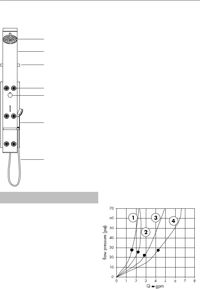
Fittings / Technical Data
Overhead shower
Aluminium profile
Tray
Bodyshower
Thermostat grip
 Shut-off/selection valve
Handshower
Shower hose
Technical Data
Minimum flow pressure |
29 psi |
Operating pressure |
max. 147 psi* |
Recommended operating pressure |
29.4-73.5 psi |
Test pressure |
235.2 psi |
Hot water temperature |
max. 158 °F |
Safety stop |
100 °F |
Flow capacity at 44 psi |
|
Hand shower (1) |
1,9 gpm |
Body showers, 6 jets (2) |
3,9 gpm |
Overhead shower |
2,8 gpm |
Overhead shower + body showers (3) |
5,5 gpm |
Hand + body showers |
5,0 gpm |
* Check applicable codes
The flow rates are limited to 2.5 gpm. These are the maximum flow rates permitted by the
Flow heater:
Applicable for flow heaters at min. 24 kW and 29 psi flow pressure before the Shower panel. Only one consumer possible, not two simultaneously.
Pressure differences:
The pressures of the cold and hot water connections must be balanced.
Maintenance
The non return valves must be checked regularly according with national or regional regulations (at least once a year!).
From • the function is guaranteed.
 Loading...