Haier HSU-12HEA03/R2, HSU-18HEA03/R2, HSU-09HEA03/R2, HSU-18HEA03-R2-I, HSU-12HEA03-R2-I Manual

INSTALLATION MANUAL
ROOM AIR CONDITIONER
WALL MOUNTED TYPE
HSU-09HEA03/R2(DB)-I
HSU-12HEA03/R2(DB)-I
HSU-18HEA03/R2(DB)-I
Read this manual before installation
Explain sufficiently the operating means to the user according to this manual.
NO.0010523238

Necessary Tools for Installation
1.Driver
2.Hacksaw 3.Hole core drill
4.Spanner(17,19 and 26mm)
5.Torque wrench(17mm,22mm,26mm) |
9.Nipper |
12.Reamer |
6.Pipe cutter |
10.Gas leakage detector or |
|
7.Flaring tool |
soap-and-water solution |
|
8.Knife |
11.Measuring tape |
|
Accessory parts
No. |
Accessory parts |
Number |
||
of |
||||
|
|
|
|
articles |
1 |
Remote controller |
1 |
||
2 |
|
R-03 dry battery |
2 |
|
3 |
|
|
|
1 |
|
|
|
Mounting plate |
|
4 |
|
|
Drain hose |
1 |
|
|
|
|
|
5 |
4X25 |
Plastic cap |
4 |
|
|
Screw |
|
|
|
|
|
|
|
|
6 |
|
|
Drain-elbow |
1 |
7 |
|
|
Cushion |
4 |
8 |
Pipe supporting plate |
1 |
||
|
||||
Optional parts for piping
Mark |
Parts name |
ANon-adhesive tape
BAdhesive tape
CSaddle(L.S) with screws
DConnecting electric cable for indoor and outdoor
EDrain hose
F Heating insulating material
GPiping hole cover
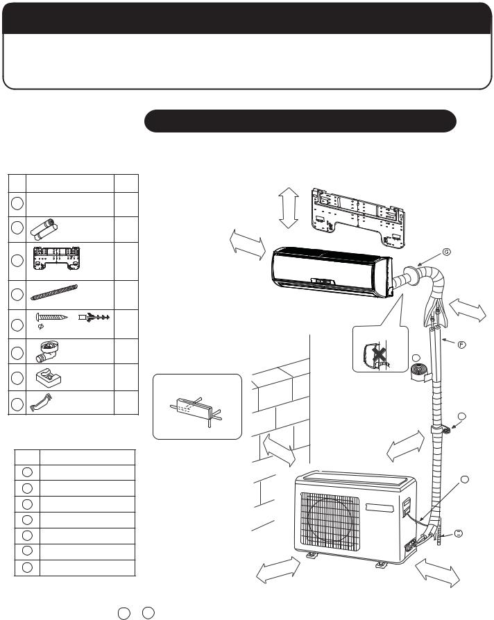
Drawing for the installation of indoor and outdoor units
The models adopt HFC free refrigerant R410A
rom ht e na
mc5
more than10cm
more than10cm
Attention must be paid to the rising up of drain hose
|
|
|
|
|
|
|
|
|
A |
Arrangement of piping directions |
|
|
|
|
|
|
|
|
|
|
Rear left |
|
|
|
|
|
|
|
|
Left |
Rear |
|
|
|
|
|
|
|
|
|
right |
|
|
|
|
|
|
|
C |
|
Right |
|
|
|
|
|
|
|
|
|
|
|
|
|
|
|
|
|
|
|
Below |
|
|
|
|
|
|
|
|
|
m |
|
|
|
|
|
|
|
cm |
|
|
|
|
|
|
|
n |
||
|
|
or |
|
|
|
|
ha |
10 |
|
|
|
e t |
|
|
|
|
ret |
|
|
|
|
h |
a |
|
|
o |
|
|
|
|
|
|
|
|
m |
|
|
|
|
|
|
|
n 1 |
|
|
|
|
|
|
|
|
|
0 |
|
|
|
|
|
|
|
|
|
|
c |
|
|
|
|
|
|
|
|
|
|
m |
|
|
|
|
D
a |
cm |
mo |
|
|
ore th |
n60 |
re th |
an |
|
m |
|
|
|
|
|
|
|
|
15c |
|
|
|
|
m |
 The marks from A to G in the figure are the parts numbers.
 The distance between the indoor unit and the floor should be more than 2m.
1
 Loading...