

Page 1

OWNER’S MANUAL
This manual contains important safety information:
read it carefully.
---------------------------------------------------------------------------------------------------------------
NEVER OPERATE THIS ATV IF YOU ARE UNDER AGE 16.
1
Page 2

INTRODUCTION
This manual will provide you with a clear understanding of the details and operation of this vehicle.
This manual includes all safety information. It provides information necessary to ride your vehicle. It also includes basic service and inspection
procedures.
AN IMPORTANT SAFETY MESSAGE :
• READ THIS MANUAL CAREFULLY AND COMPLETELY BEFORE OPERATING YOUR VEHICLE. MAKE SURE YOU UNDERSTAND ALL
INSTRUCTIONS.
• PAY CLOSE ATTENTION TO THE WARNING AND CAUTION LABELS ON THE VEHICLE.
• NEVER OPERATE AN ATV WITHOUT PROPER TRAINING OR INSTRUCTION.
• NEVER OPERATE THIS ATV IF YOU ARE UNDER AGE 16.
IMPORTANT MANUAL INFORMATION :
FAILURE TO FOLLOW THE WARNINGS CONTAINED IN THIS MANUAL CAN RESULT IN SERIOUS INJURY OR DEATH.
2
Page 3

Particularly important information is distinguished in this manual by the following notations:
ATTENTION:
the Safety Alert Symbol means ATTENTION! BE ALERT! YOUR SAFETY IS INVOLVED!
WARNING:
CAUTION :
NOTE:
failure to follow WARNING instructions could result in severe injury or death to the vehicle operator, a
bystander or a person inspecting or repairing the vehicle.
a CAUTION indicates special precautions that must be taken to avoid damage to the vehicle.
a NOTE provides key information to make procedures easier or clearer.
3
Page 4

IMPORTANT WARNING
This vehicle has been projected and built for the off-rode use. The employment on asphalted roads and on roads opened to traffic needs of some
precautions.
This ATV is in specification with both the noise levels laws and the standards for spark arrested on exhaust box, in force for the off-rode vehicle at
the building moment.
Please, check the laws, which regulate the local circulation, before using the vehicle.
4
Page 5

CONTENTS:
WARNING AND SPECIFICATION LABELS
2. SECURITY INFORMATIONS
3.DESCRIPTION AND MACHINE IDENTIFICATION
Progressive number record
Vehicle identification number
4. CONTROL FUNCTIONS
Main switch
Throttle lever
Handlebar switches
Front brake pedal
Rear brake pedal
Parking brake
Speed limiter
Seat
Fuel tank cap
Front shock absorber adjustment
Rear shock absorber adjustment
5. PRE-OPERATION CHECK 9. MAINTENANCE RECORD
6. OPERATION
To start out and accelerate
To decelerate
Engine break-in
Parking
Parking on a slope
7. PERIODIC SERVICE
Engine oil
Idle speed adjusted
Throttle level adjustment
Inspecting the brake fluid level
Front brake lever free play adjustment
Brake lever lubrification
Fuse replacement
Replenishing the battery fluid
Replacing the headlight bulb
Air filter cleaning
8. TECHNICAL CHARACTERISTICS
5
Page 6
Front and rear brakes
Fuel
Engine oil
Throttle lever
Lights
Switches
Tires
Wear limit of the tires
6
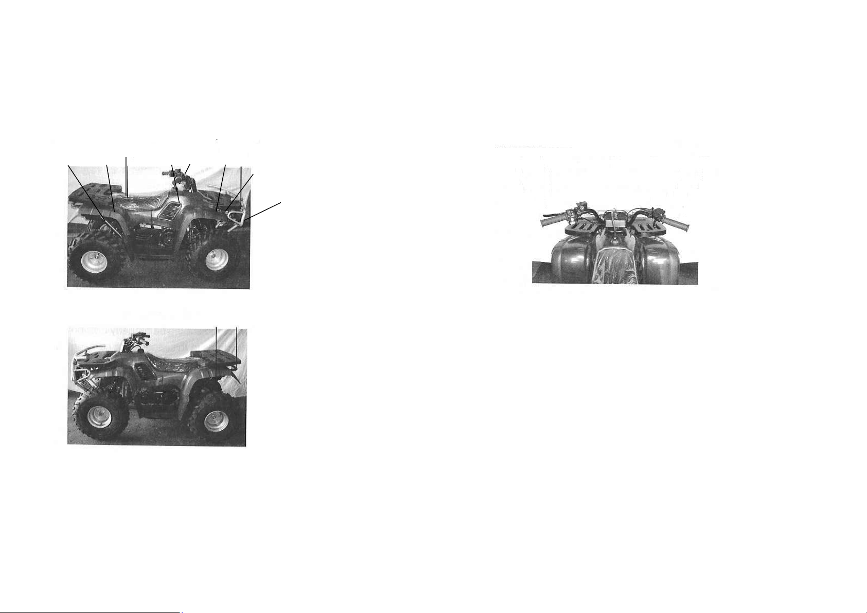
LOCATION OF THE "WARNING AND SPECIFICATION LABELS"
2
Read and understand all of the labels on your quad.
They contain important informations for safe and proper operation of your
quad.
In case of doubt, consult the distributor or an authorized dealer.
6
Page 7
Never remove any labels from your quad. If a label becomes difficult to
read or comes off, a replacement label is available from your dealer..
3
1
7
Page 8
1 - WARNING
Some indications which are contained in the
1 and 4 labels, that you find on your vehicle,
are refered to the Countries where the ATV
is not homologated for the employment on
road or for the passenger transport.
Even if in italy it is not compulsory, the use
of the helmet is advisable. NEVER use the
vehicle under the effect of substances,
which may alter the driving abilities.
4 – WARNNG
This label is not refered to the Countries
where then vehiche is NOT
homologated for the passenger
transport.
_____________________________
5
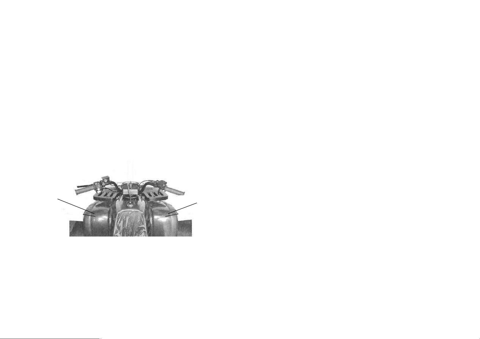
LOADING LIMIT/ WARNING
(Front luggage-rack)
30kg (66 lbs)
NEVER sit in this point.
2 – WARNING
Operating this ATV if you are under the age of
16 increased your chance of severe injury or
death.
NEVER operate this ATV if you are under age
16..
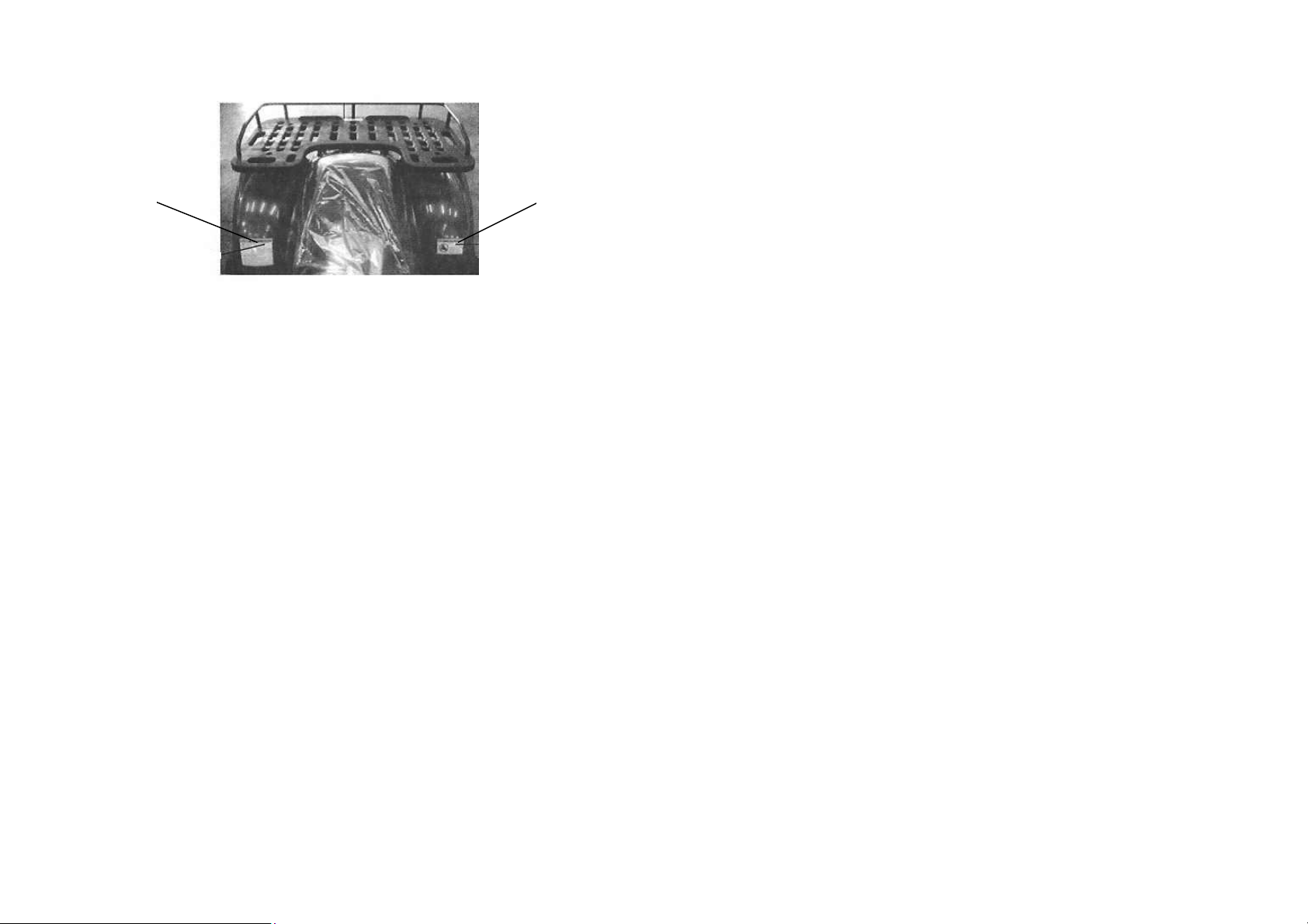
6
LOADING LIMIT/WARNING
(Rear luggage-rack)
45 kg (99 lbs)
NEVER sit in this point.
Improper tire pressure or overloading can cause
loss of control.
Loss of control can result in severe injury or
death.
OPERATING TIRE PRESSURE: set with tires
cold.
• Recommended:
FRONT 0,25 bar = kgf/cm².
REAR 0,25 bar = kgf/cm².
• Minimum
FRONT 0,22 bar = kgf/cm².
REAR 0,22 bar = kgf/cm².
• Never set tire pressure bellow minumum. It
could cause the tire to dislodge from the rim.
LOADING/TRAILER TOWING
CHECK IF THE TOWING OF A BARROW IS
ALLOWED.
• Cargo or a trailer can affect stability and
handling.
Read owner’s manual before loading or
towing.
• When loading with cargo or towing a trailer,
reduce speed and allow more room to stop.
• Avoid hills and rough terrain.
Maximum Vehicle Load : 180 kg, (396 lbs),
includes weight of operator, cargo and
accessories (and if applicable, trailer tongue
weight).
3 - WARNING
8
Page 9

SECURITY INFORMATIONS
WHEN YOU DRIVE AN ATV YOU MUST BE VERY CAREFUL
An ATV reacts differently from the other vehicles, like motocycle and cars. The wrong use may cause rapidly a crash or the tipping, both during the
normal manoeuvres and bending or overtaking hills and obstacles.
THE NON-OBSERVANCE OF THE FOLLOWING DIRECTIONS COULD CAUSE SERIOUS INJURIES
• Read carefully the manual and the labels, following the procedures which are described.
• NEVER use an ATV without an adequate period of apprenticeship.
• If you are under the age of 16, you should not use an ATV with a higher displacement than 50 cc.
• The passenger transport needs more caution.
• Driving on roads opened to traffic or on asphalted surfaces, needs a particular care.
• It is advisable the use of the helmet und of adequate cloaths, which are composed by gloves, robust shues, a jacket with sleeves and long
trousers.
• NEVER use the vehicle, after having substances, which may alter the driving ability
• Do not drive , keeping an excessive speed, compared to your abilities and to the route conditions.
• NEVER do jumps, rearings, or other acrobatics.
9
Page 10

• Always check your ATV, before using it, to verify its security during the emploi.
• Using the ATV, always keep both the hands on the handlebar and the feet on the running boards.
• Do not use the ATV in rivers with strong currents or in deeper waters than 25 cm. (10 inch.).
• Always use tires of the type and of the measures, which are specified in this manual and pump them at the pressures indicated in the manual.
• Do not change the ATV, installing or using unsuitable accessories.
• Do not exceed the loading capacity, which is established for your ATV . The loading must be suitably arranged and fixed. Regulate the speed
and follow the instructions of this manual, reguarding the loading and the towing of a barrow. Keep a bigger security distance in case of braking.
WARNING
• Always switch off the engine, during the refuelling.
• Do not start the engine or drive the vehicle in closed places to avoid potential risks.
10
Page 11
DESCRIPTION AND MACHINE IDENTIFICATION
5 6 7
1
8
2
9
10
3 4
1. Battery
2. Headlight
3. Seat lock
4. Rear bumper
5. Handlebar
6. Rear brake lever
7. Main swutch
8. Throttle lever
9. Speed limiter
10. Front brake lever
11
Page 12
IDENTIFICATION NUMBERS RECORD
Record the vehicle identification number and engine I.D.
number in the spaces provided for assistance when ordering
spare parts from dealer or for reference in case the vehicle is
stolen.
1. VEHICLE IDENTIFICATION NUMBER
2. ENGINE I.D. NUMBER
The vehicle identification number is stamped on the frame.
Note: The vehicle identification number is used to identify your ATV.
The information of vehicle identification number and engine I.D.
number will be needed to order spare parts from your dealer.
12
Page 13

CONTROL FUNCTIONS
Main switch
Functions of the respective switch positions are as follows:
ON: Engine can be started only at this position and the headlight
and taillight come on when the light switch is on.
OFF: All electrical circuits are switched off. The key can be
remove in this position.
Throttle Lever
Once the engine is running, movement of the throttle lever will increase
the engine speed.
Regulate the speed of the engine by varying the throttle position.
Because the throttle is spring-loaded, the engine will decelerate, and
the engine will return to an idle any time the finger is removed from the
throttle lever.
Before starting the engine, check the throttle to be sure it is operating
smoothly. Make sure it returns to the idle position as soon as the lever
is released.
13
Page 14

Handlebar switches
1 2 3
1. Engine stop button
2. Lights switch
3. Start button
Engine stop button
The engine stop button checks the switching on and it can be
used every time it is necessary to stop the motor, above all in
case of emergency.
The motor cannot be started or works when the stop button is
located in the ……. position.
Start button
Pressing this button, the starter starts the motor.
CAUTION:
See starting instructions prior to starting engine.
Lights switch
Turn the lights switch to the position ON to switch on the position lights
and the rear-light.
CAUTION:
Do not use the half-lights when the motor is stopped for more then 20
minutes. The battery could discharge and for this reason the starter
may not work correctly. If it will happen, remove the battery and
recharge it.
14
Page 15

A
Front brake lever
The front brake is located on the right handlebar.
Pull it toward the handlebar to apply the front brake or parking brake.
Foot brake pedal
The brake pedal is located on the rigth side of the vehicle. Push down on the
pedal to apply the rear brake.
Parking Brake
pply the brake lever while pushing the stopper, then push in the stopper to
apply the parking brake.
Squeeze the front brake lever to release the parking brake.
15
Page 16

A
Adj
Speed limiter
The speed limiter keeps the throttle from fully opening, even
when the throttle lever is pushed to the maximum. Screwing
in the adjuster limits the maximum engine power available
and decreases the maximum speed of the ATV.
Locknut
uster
WARNING:
Do not turn the speed adjuster out more than 12 mm.
lways make sure the throttle lever free play is 3~5mm
(0,12~0,20in.).
Seat
To remove the seat, pull the seat lock lever upward and pull up the
seat at the rear.
To install the seat, insert the lobe on the seat front into the
receptable on the frame and push down the seat at the rear.
16
Page 17

A
Fuel tank cap
Remove the fuel tank cap by turning it counterclockwise.
utomotive gasoline with octane number of 91 or higher may be
used.
After refueling, be sure to tighten the tank cap firmly.
17
Page 18

Front shock absorber adjustment
The spring preload can be adjusted to suit the vehicle’s load
and riding conditions.
Spring preload adjustment :
To increase the spring preload, turn the adjuster in direction a.
To decrease the spring preloaded, turn the adjuster in
direction b.
Rear shock absorber adjustment
The spring preload can be adjusted to suit the vehicle’s load
and riding conditions.
Spring preload adjustment :
To increase the spring preload, turn the adjuster in direction
a.
To decrease the spring preload, turn the adjuster i
direction b.
Standard position: A
A—Minimum (Soft) E—Maximum (Hard)
Standard position: A
WARNING:
Uneven adjustment on different sides can cause poor
handling and loss of stability.
18
Page 19

PRE-OPEATION CHECKS
Before using this ATV, check the following points:
ITEM ROUTINE
Brakes Check operation, free plqy, fluid level and fluid leakage.
Fill with DOT 4 (or DOT 3) brake fluid if necessary.
Parking brake Check operation, condition and cable free play.
Fuel tank Check fuel level.
Fill with fuel if necessary.
Engine oil Check oil level.
Fill with oil if necessary.
Throttle Check for proper throttle cable operation.
Wheels and tires Check tire pressure, wear and damage.
Fittings and Fasteners Check all fittings and fasteners.
Lights Check for proper operation.
Batteriy Check fluid level.
Fill with didtilled water if necessary.
ATTENTION:
Always check each item in the above list prior to operating your ATV.
19
Page 20

Front and rear brakes
1. Check the operation and free play of the levers and pedal.
They should move smoothly and there should be a firm
feeling when the brakes are applied. If not, have the vehicle
inspected by your dealer.
2. Brake fluid level.
Check the brake fluid level. Add fluid if necessary.
Recommended brake fluid: DOT 4.
NOTE: If DOT 4 is not available, DOT 3 can be used.
3. Brake fluid leakage.
Check to see if any brake fluid is leaking out of the pipe joints or
master cylinder.
Apply the brakes firmly for one minute. If there is any leaking, have
the vehicle inspected by your dealer.
4. Brake operation
Test the brakes at slow speed after starting to make
sure they are working properly. If the brakes do not
provide proper braking performance, inspect the
brake pads for wear.
Fuel:
Make sure there is sufficient fuel in the tank.
Fuel tank capacity:
Total: 5,6 L (1,5 gal.)
The engine has been designed to use regular gasoline
with RON of 91 or higher.
20
Page 21

Engine oil:
Make sure the engine oil is at the specified level. Add oil if necessary.
Recommended oil:
Recommended engine oil classification: API Service SE, SF, SG type or higher.
ATTENTION: Do not add any anti-friction modifier to ensure proper clutch function.
Oil quantity in engine: 1L (1 gt.).
21
Page 22

Throttle lever:
Check to see that the throttle lever operate correctly. It must open smoothly and spring back to idle position when released. Repair if necessary for
proper operation.
Lights:
Check the headlight and taillight to make sure they are in working condition. Repair if necessary for proper operation.
Switches:
Check the operation of the headlight switch, engine stop switch and any other switches. Repair if necessary for proper operation.
Battery:
Check fluid level and top-off if necessary. Use only distilled water if refilling.
Tires:
In order to have the highest efficienty & safety operation, please pay attention to
The follows:
1 Use the following tires:
Measure
Front 21x7x10
Rear 22x10x8
22
Page 23

2. The tires should be set to the recommended pressure.
Recommended tire pressure:
Front 25 Kpa (0,25kgf/cm², 3,6 psi)
Rear 25 kPa (0,25kgf/cm², 3,6 psi)
Check and adjust tire pressures when the tires are cold.
Tire pressures must be equal on both sides.
3. Tire pressure below the minimumspecified could cause the tire to dislodge from the rim under severe riding conditions.
Minimums tire pressure:
Front 0,22 kPa (0,22kgf/cm², 3,2 psi)
Rear 0,22 kPa (0,22kgf/cm², 3,2 psi)
4. ATTENTION! Use no more than the following pressures when seating the tire beads.
Front 250 kPa (2,5 kgf/cm², 3,6 psi)
Rear 250 kPa (2,5 kgf/cm², 3,6 psi)
Higher pressures may cause the tire to burst. Inflate the tires very slowly and carefully.
Fast inflation could cause the tire to burst.
5. The wear limit
When the tire groove decreases to 3 mm (0,12 in.) due to wear, replace the tire.
23
Page 24

WARNING:
Operation ATV without being familiar with all controls is
extremely dangeriìous.
Freezing control cables in cold weather is extremely
dangerous. Make sure everything is work smoothly before
starting.
To start out:
1. Release the throttle lever.
ATTENTION:
Always close the throttle while shifting gears. Otherwise,
damage to the engine and drive train may result.
CAUTION:
This procedure must be used on all the ATV models
(includes the 125 with automatic gear) to go into reverse:
the vehicle must be motionless and the engine should run
at minimum revolutions otherwise it may damage the
transmission.
HOW TO USE THE GEAR (ONLY FOR THE 200 MODEL).
To accelerate:
2. Open the throttle gradually.
3. Once the vehicle has attained adequate speed, release
the throttle lever.
OPERATION
4. Shift into second gear and release the shift pedal.
5. Open the throttle gradually.
6. Follow the same procedure when shifting to the next higher
gear.
To decelerate:
When slowing down or stopping, release the throttle and apply the
brakes smoothly and evenly. As you slow down, shift to a lower
gear.
Be sure that the engine has sufficiently slowed before enaging a
lower gear.
24
Page 25

A
A
ENGINE BRAKE-IN
ATTENTION: The first 20 Hrs for engine break-in is very important,
never exceed the funning condition listed below:
1. 0-10 hours:
Avoid continuous operation above half throttle.
llow a cooling off perod of live to ten minutes after every hour of
operation. Vary the speed of the vehicle from time to time. Do not
operate it at one set throttle position.
2. 10-20 hours:
Avoid prolonged operation above ¾ throttle.
Rev the vehicle freely through the gears but do not use full throttle
at any time.
3. After break-in
Avoid prolonged full throttle operation. Vary speeds occasionally.
Parking:
When parking, stop the engine and shift into neutral.
Turn the fuel cock to "OFF" and apply the parking brake.
Parking on a slope:
void parking on slopes. If you must park on an incline, put
the engine ina low gear, apply the parking brake, and block
the wheels with rocks or other objects.
ATTENTION: MAXIMUM LOADING LIMIT
Vehicle loading limit (total weight of cargo, rider and
accessoires, and tongue weight): 150 kg. (264 lb).
25
Page 26

PERIODIC SERVICE/LUBRIFICATION
ITEM ROUTINE
Valves Check valve clearance
Adjust if necessary
Spark plug Check condition
Adjust gap and clean
Replace if necessary
Air filter Clean
Replace if necessary
Carburetor Check idle speed/starter
operation
Adjust if necessary
Cylinder
head cover
breather
sy stem
Exhaust
system
Check breather hose for cracks
or damage
Replace if necessary
Check leakage
Retighten if necessary
Replace gasket if necessary
PERIODIC SERVICE
INITIAL EVERY
1 month 3 months 6 months 6 months 1 year
X X X X
X X X X X
Every 20 ~ 40 hours
(More often in wet or dust areas.)
X X X X
X X X
X X X
26
Page 27

ITEM ROUTINE
Fuel line Check fuel hose for cracks or
damage
Replace if necessary
Engine oil Check oil level weekly
Replace (Warm engine before
draining.)
Engine oil
strainer
Clean
Brake Check operation/fluid leakage
Correct if necessary
Tires Check pressure and wear
Replace if damaged
Wheel
bearings
Check bearing assembly for
looseness/damaged
Replace if damaged
Steering
system
Check operation
Replace if damaged
Check toe-in
Adjust if necessary
INITIAL EVERY
1 month 3 months 6 months 6 months 1 year
X X X
X X X X
X X X
X X X X X
X X X X X
X X X X
X X X X X
27
Page 28

ITEM INITIAL EVERY
ROUTINE
1 month 3 months 6 months 6 months 1 year
Check specific gravity
Battery
Check that the breather hose is
positioned properly
Check liquid height
WARNING:
Never service the engine while still running!
X X X X X
28
Page 29

Engine oil
1. Engine oil level measurement
a. Place the vehicle on a level place.
b. Warm up the engine for several minutes and stop it.
c. Wait a few minutes until the oil level settles before
checking.
d. Remove the dipstick and wipe it off with a clean rang.
Insert the dipstick in the filter hole without screwing it in.
e. Remove the dipstick and insect the oil level.
f. The oil level should be between the maximum and
minimum marks. If the level is low, add oil to raise it to
raise it to the proper level.
CAUTION:
Be sure no foreign material enters the crankcase.
2. Engine oil replacement and oil strainer cleaning
a. Place the vehicle on a level place.
b. Warm up the engine for several minutes and
stop it.
c. Place a container under the engine.
d. Remove the dipstick and drain plug to drain
the oil.
29
Page 30

Idle speed adjustment
NOTE: for this operation a diagnostic instrument must be used
(Revolution counter).
1. Start the engine and warm it up for a few minutes at
approximately 1,000 to 2,000 r/min. Occasionally rev the engine
to 4,000 to 5,000 r/min. The engine is warm when it quickly
responds tothe throttle.
2. Connect the tachometer and set the idle to the specified
idling speed by adjusting the throttle stop screw. Turn the screw
into increase engine speed, and out to decrease engine speed.
SPECIFIED IDLE SPEED: 1.700 rpm +/- 100
Throttle lever adjustment
NOTE: Adjust the engine idling speed before adjusting the
throttle lever free play.
1. Loosen the locknut.
2. Turn the adjusting bolt until the throttle lever free play is
3 ~ 5 mm (0,12 ~ 0,20 in).
3. Tighten the locknut.
1. Locknut 2. Adjusting bolt
a. 3-5 mm. (0.12-0.20 in.)
30
Page 31

Inspecting the brake fluid level
Insufficient brake fluid may let air enter the brake system,
possibly causing the brakes to become ineffective.
Bofore riding, check that the brake fluid is above the
lower level and replenish when necessary.
Use only the designated quality brake fluid.
Recommended brake fluid DOT 4.
NOTE:
If DOT 4 is not available, DOT 3 can be used.
Front brake lever free play adjustment
The front brake lever free play should be 20 ~ 25 mm (0,80 ~ 1,0
in). If the free play is incorrect, adjust it as follows.
1. Adjust the screw under the brake lever with finger.
Adjust same turns of screw on both side of brake.
1. minimum level mark “LOWER”
31
Page 32

Brake level lubrification
Lubrificate the pivot of each lever and pedal.
Use SAE 10W30 motor oil.
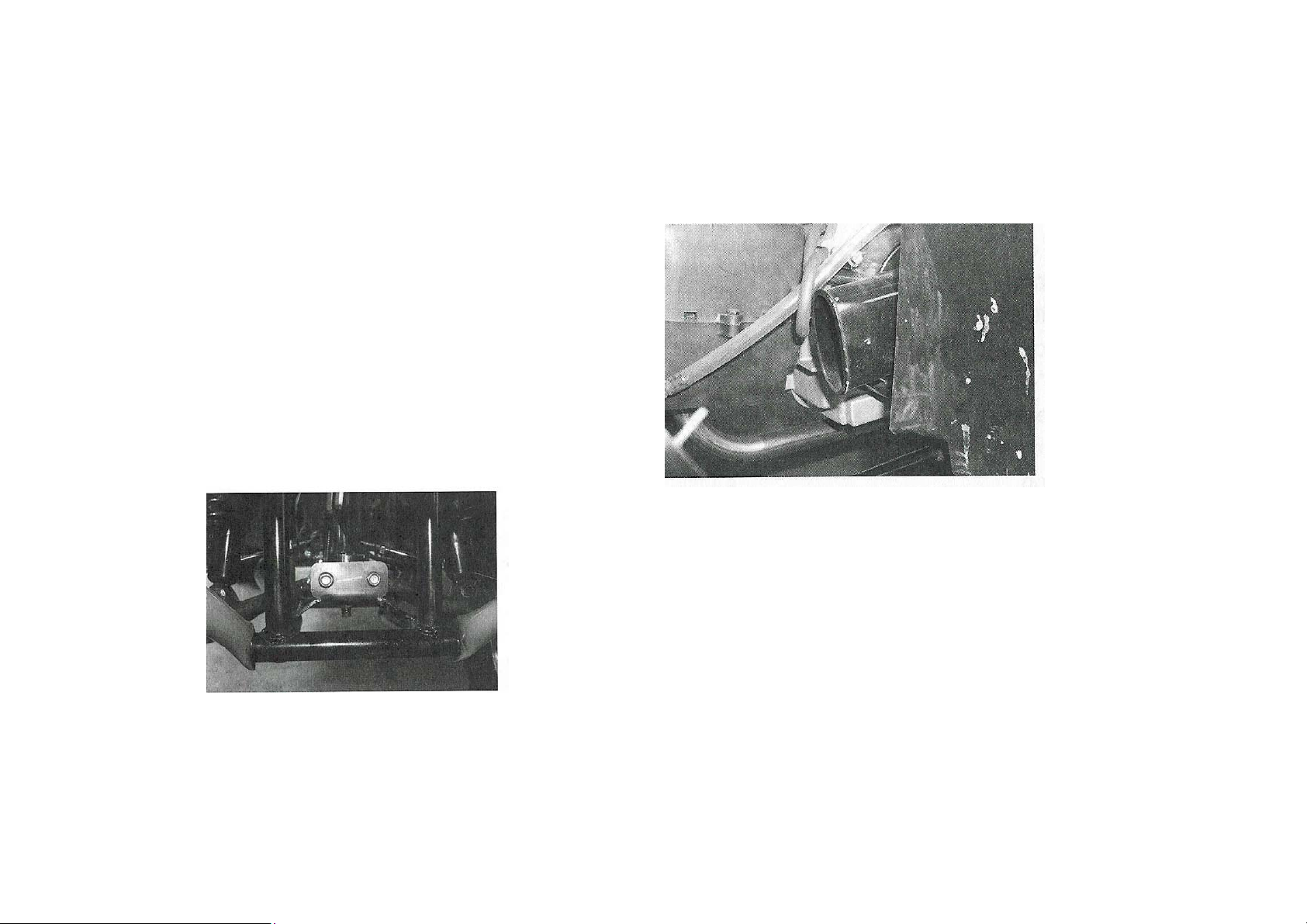
Drive Chain Adjustment
Fuse replacement
If the fuse is blown. Turn off the main sw itch and install a new
fuse of the specified amperage. Then turn on the switches. If
the fuse immediately blows again, consult your dealer.
Specified fuse: 30 A.
1. Unlock the fastening screw of swing arm.
2. Swing the rear axle bearing holder back and forth to
reach suitable chain tension.
3. Lock the fastening screw of swing arm.
1. Main fuse
WARNING:
Never use an improper fuse.
An improper fuse can cause damage to the electrical system
which could lead to a fire.
CAUTION:
To prevent accidental short-circuiting, turn off the main
switch when checking or replacing a fuse.
32
Page 33

A
Replacing the battery fluid
poorly maintained battery will corrode and discharge quickly.
The battery fluid should be checked at least once a month.
1. The level should be between the upper and lower level
marks. Use only distilled water if refilling is necessary.
1) Maximum level mark “UPPER LEVEL”.
2) Minimum level mark “MINIMUM LEVEL”.
Replacing the headlight bulb
If the headlight bulb is burnt, remove the headlight unit
assembly, take out the defective bulb and replace a new one.
Spank plug inspection
NOTE:
STANDARD spark plug: NGK or CHAMPION
Spark plug gap: 0.6-0.7 mm. (0.024-0.028 in.)
Air filter cleaning
1. Remove the seat.
2. Remove the air filter case cover.
3. Remove the air filter element, and separate it from the
guide.
4. Blow the dust on element with air or replace it.
33
Page 34

TECHNICAL CHARACTERISTICS
MODEL QUAD DX125
Dimensions:
Overall length 1,660 mm
Overall width 900 mm
Overall height 1,070 mm
Wheel base 750 mm
Minimum ground clearance 1,090 mm
Minimum turning radius 150 mm
Basic weight:
WITH OIL AND FULL FUEL TANK 150 kg
Engine:
Engine type Forced air-cooled, 4 stroke, OHC
Cylinder arrangement Forward inclined single cylinder
Displacement 124 CC
Bore x stroke 52,4 x 57,8 mm
Compression ratio 9,4 : 1
Starting system Electric starter / kick starter
Lubrification system Wet pump
34
Page 35

MODEL QUAD DX125
Engine oil:
Recommended engine oil classification :
Quantity
Air filter:
Type API Service SE,SF,SG or higher.
1.0 L.
Dry element
Fuel:
Type Unleaded fuel
Fuel tank capacity 5,6 L
Carburetor:
Type/quantity
Manufacturer
Spark plug:
Type/Manufacturer NGK or Champion
Spark plug gap 0.6-0.7 mm
Keihin/Reinmech PD-24D
35
Page 36

MODEL QUAD DX125
Chassis:
Frame type En tubes an acier à haute résistance
Caster angle 4°
Transmission:
Primary reduction system CVT
Secondary reduction system Chain
Secondary reduction ratio Z 17-34
Transmission type Automatic
Tire:
Type Tubeless
Size Front AT 20 x 7-8” Rear AT 20 x 9-8”
Brake:
Front brake Type Dual drum brake
Operation Right hand operation
Rear brake Type Single disc brake
Operation Left hand operation
Suspension:
Front suspension Single wishbone
Rear suspension Swing-arm
36
Page 37

MODEL QUAD DX125
Shock absorber:
Front Coil spring/Oil damper
Rear Coil spring/Oil damper
Wheel travel:
Front 150 mm
Rear 180 mm
Electrical:
Ignition system CDI
Generator system CDI magneto
Battery/ type/voltage/capacity 12V-
Bulb voltage, wattage x quantity:
Headlight 12V, 30w/30W x 2
Taillight 12V, 7,5W x 1
37
Page 38

MAINTENANCE RECORD
Copies of work orders and/or receipts for parts you purchase and install will be required to document maintenance done in accordance with the
warranty. The chart below is printed only as a reminder to you that the maintenance work is required. It is not acceptable proof of maintenance
work.
MAINTENANCE
INTERVAL
1 month
2 months
3 months
4 months
5 months
6 months
12 months
18 months
24 months
30 months
36 months
48 months
54 months
60 months
CAUTION: to improve the product, the buider reserve to change the building characteristics, without the notice duty. If your vehicle building
characteristics would be different than what is described in the previous pages or in case of doubt during the consultation of this manual, address to
the dealer or to an authorized assistance center.
DATE OF SERVICE MILEAGE SERVICING DEALER
NAME AND ADDRESS
REMARKS
38
 Loading...