

SHOWER AND DIVERTER ROUGH SET
CONJUNTO DE DUCHA Y DESVIADOR VÁLVULA
This product complies with ASME/ANSI A112.18.1
and CSA B 125 Standards.
Este se encuentra conforme con losestandares
producto
de ASME/ANSI A112.18.1 y de CSA B 125.
Dear Customer Estimado Cliente
ENGLISH
Thank you for selecting our product. We are confident we can fully satisfy Muchas gracias por elegir nuestro producto. Estamos seguros que podemos
your expectations by offering you a wide range of technologically advanced satisfacer completamente sus expectativas ofreciéndole una amplia variedad
products which directly result from our many years of experience in faucet
and fitting production.
For easy installation of your Para la instalación fácil de su producto
GRAFF product you will need: de la GRAFF usted necesitará:
to READ ALL the instructions completely before beginning, LEER TODAS las instrucciones completamente antes de comenzar,
to READ ALL the warnings, care and maintenance information. LEER TODA la información sobre las advertencias,
You should have the following tools: cuidado y mantenimiento.
Hacksaw or Tubing Cutter
Solder
Rags
Propane Torch
ENGLISH
Installation Instructions Instrucciones de Instalación
~
ESPANOL
de productos tecnológicamente avanzados que resultan directamente de
muchos años de experiencia en grifos y su producción apropiada.
~
ESPANOL
Usted debe tener las herramientas siguientes:
Sierra para metales o cortatubos
Suelda
Trapos
Soplete de propano
IMPORTANT INFORMATION INFORMACIÓN IMPORTANTE
ENGLISH
#Please read all instructions before beginning this installation.
#Installer to supply 1/2″ Nominal (5/8″ O.D.) copper tubing.
#Shut off the main water supply.
#There instructions cover installation on both finished deck or rim
installations and rough/unfinished deck installations.
#Please take care while drilling the holes – their diameters cannot
exceed maximum dimensions given in installation instruction. The
diameter of opening for a diverter valve and handshower connector
shall be MAX Ø1-1/4” (Ø32mm).
#The installed finished deck material must fit closely to diameters of
plaster guards.
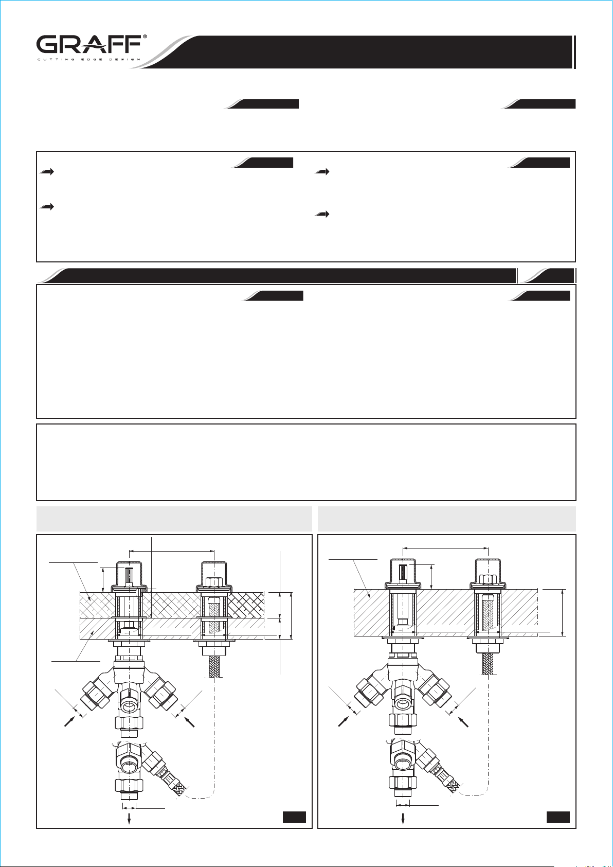
WARIANT 1
Rough/unfinished Deck Installation (to be finally covered with a finish
layer) - see fig. 1
WARIANT 2
Finished Deck Installation or Rim Mount Installation - see fig. 2
FINISHED DECK INSTALLATION OR RIM MOUNT INSTALLATION
FINISHED MATERIAL
MATERIAL DE ACABADO
ROUGH/UNFINISHED DECK INSTALLATION
4" - 12"
(101.6mm - 304.8mm)
A
Hmax = F + 1/8" (4mm)
Hmin = F - 1/16" (1mm)
F = 5/16" - 1-1/4"
(F = 8mm - 31mm)
1
~
ESPANOL
#Por favor, lea atentamente las instrucciones antes de comenzar esta
instalación.
#El instalador debe proveer el tubo de cobre de 1/2″ nominal (5/8″ D.E.).
#Cierre el suministro principal de agua.
#Estas instrucciones cubren la instalación en cubierta acabada o en
borde e instalaciones en cubierta no acabada.
#Cuide que los diámetros de los orificios taladrados no superen las
dimensiones mxi mas inficadas en las instrucciones de montaje.
Diámetro del orificio para la válvula de desviador y para el racor de la
regadera debe ser de MAX Ø1-1/4” (Ø32mm).
#El material de acabado de la cubierta instalado debe quedar muy cerca
de los diámetros de los protectores de yeso.
WARIANT 1
Instalación del conjunto en cubierta acabada „cruda” (finalmente,
cubierta con una capa de acabado) - ver el fig. 1
WARIANT 2
Instalación del conjunto en cubierta acabada o en borde de la
bañera - ver el fig. 2
INSTALACIÓN DEL CONJUNTO EN CUBIERTA ACABADA O EN BORDE DE LA BAÑERA
FINISHED DECK INSTALLATION OR RIM MOUNT INSTALLATION
FINISHED DECK OR RIM
CUBIERTA ACABADA O EL
BORDE DE LA BAÑERA
4" - 12"
(101.6mm - 304.8mm)
A
ROUGH DECK
CUBIERTA NO ACABADO
Ø5/8" O.D.
IOG 2824.90
MAX 1-1/4" ( 32mm)Ø Ø MAX 1-1/4" ( 32mm)Ø Ø
Ø5/8" O.D.
Ø5/8" O.D.
MAX. 2-3/16"
MAX. 1"
(MAX. 25mm)
(MAX. 56mm)
Ø
5/8" O.D.
MAX 1-1/4" ( 32mm)Ø Ø MAX 1-1/4" ( 32mm)Ø Ø
Ø5/8" O.D.
Ø5/8" O.D.
1 2
1
Rev. 1 June 2010
MAX. 2-3/16"
(MAX. 56mm)
This product complies with ASME/ANSI A112.18.1
and CSA B 125 Standards.
Este se encuentra conforme con losestandares
producto
de ASME/ANSI A112.18.1 y de CSA B 125.
Diverter Rough Configuration with Trim Sets
Configuración de desviador con conjuntos de acabado
Conjunto para acabado para el conjunto desviadora
Trim Set for Diverter
Model/Modelo
SHOWER AND DIVERTER ROUGH SET
CONJUNTO DE DUCHA Y DESVIADOR VÁLVULA
Installation Instructions Instrucciones de Instalación
Dimensiones de montaje para tipos desviadores corrispondientes
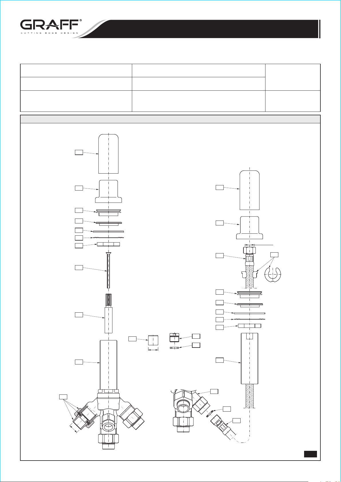
Assembly Dimensions for Diverter Type
„A”
±1/16” (±1mm)
Assembly of the Valve
according to Detail
Montaje de la válvulas
M.E.25 6156-LM41B-**-T
QUBIC TRE 6255-LM39B-**-T
10
9
8
7
6
5
4
1057
1-3/16” (30mm)
10
12
FIG. 1, 2
9
M15x1
14
15
Ø5/8" O.D.
3
8
7
2
6
5
4
16
17
18
Ø5/8"
1
11
1
13
12
IOG 2824.90
3
2
Rev. 1 June 2010

This product complies with ASME/ANSI A112.18.1
and CSA B 125 Standards.
Este se encuentra conforme con losestandares
producto
de ASME/ANSI A112.18.1 y de CSA B 125.
DIVERTER VALVE
1
HEAD SPINDLE EXTENSION
2
BOLT
3
NUT (2 PCS.)
4
METAL WASHER (2 PCS.)
5
RUBBER WASHER (2 PCS.)
6
FLANGED NUT (2 PCS.)
7
COLLAR (2 PCS.)
8
COLLAR PLASTER GUARD (2 PCS.)
9
VALVE PLASTER GUARD (2 PCS.)
10
THREADED CONNECTOR
11
HOSE M15x1 FT – M15x1 MT, 19-11/16” (500mm) LENGTH
12
FLAT WASHER (2 PCS.)
13
HOSE STOP
14
COPPER PIPE CONNECTOR
15
CAP
16
PLUG
17
FLAT WASHER
18
SHOWER AND DIVERTER ROUGH SET
CONJUNTO DE DUCHA Y DESVIADOR VÁLVULA
Installation Instructions Instrucciones de Instalación
ENGLISH
VÁLVULA DE DESVIADOR
1
EXTENSIÓN DEL FUZO DEL CABEZAS
2
TORNILLO
3
TUERCA (2 PIEZAS)
4
ARANDELA DE METAL (2 PIEZAS)
5
ARANDELA DE GOMA (2 PIEZAS)
6
TUERCA CON BRIDA (2 PIEZAS)
7
BRIDA (2 PIEZAS)
8
PROTECTOR DEL YESO DE BRIDA (2 PIEZAS)
9
PROTECTOR DEL YESO DE VÁLVULA (2 PIEZAS)
10
RACOR ROSCADO
11
MANGUERA M15x1 RI – M15x1 RE, LONGITUD DE 19-11/16”
12
(500mm)
JUNTA PLANA (2 PIEZAS)
13
BLOQUEO DE LA MANGUERA
14
TUBO CONECTOR DE COBRE
15
TAPA
16
TAPÓN
17
JUNTA PLANA
18
ESPANOL
~
MT – male thread
FT – female thread
ENGLISH
In case of Rough/unfinished Deck Installation:
Diverter valve installation:
Use the following equation to calculate the thickness of the finish layer in
order to execute the valve installation in a proper way:
#Sum the thickness of the finish layer with A dimension required
between finished surface level and the upper surface of the head
spindle elongation piece (see fig. 1)
Tiles/Surface finish material + A dimension = Installation height
ROUGH INSTALLATION INSTALACIÓN PRELIMINAR
ENGLISH
1. Make holes of the dimensions and positions given in fig. 1 and 2.
2. Screw the nut (4) onto the diverter valve (1) and fit the metal (5)
and rubber gasket (6) - fig. 3.1. Screw the nut (4) onto the
threaded connector (11) and fit the metal (5) and rubber gasket
(6) - fig. 3.1. Insert the valve (1) and threaded connector (11) into
the correct hole, from the underside of the surface.
3.1 Rough/unfinished Deck Installation:
Before fitting the finishing layer, screw the flanged nut (7) onto the
diverter valve (1) from the top - fig. 3.2. Adjust the valve (1)
position using the nut (4) and flanged nut (7) to obtain the correct
'A' dimension after placing the finish layer. Next, screw the second
flanged nut (7) onto the threaded connector (11) from the top;
adjust the connector (11) position using the nuts. The minimum
protrusion of the connector after fitting the finish layer is 5/32”
(4mm) - fig. 3.3.
3.2 Finished Deck Installation or Rim Mount Installation:
Screw the collar (8) onto the diverter valve (1) from the top - fig.
3.6. Adjust the valve (1) position using the nut (4) and collar (8) to
obtain the correct 'A' dimension after fitting the finish layer. Next,
screw the second collar (8) onto the threaded connector (14) from
the top; adjust the connector (14) position using the nut (4) and
collar (8). The minimum protrusion of the connector after fitting the
finish layer is 5/32” (4mm).
4. Solder the diverter valve (1) to the bath tap valves and to the tap
supply according to fig. 3.3. The diverter valve has connectors for
1/2" copper pipes. Solder a cap (16) to one of the connections of the
T-pipe (T) of the spout supply. Connect the central outlet of the
diverter valve to the uncapped connection of the T-pipe (T).
5.1 Rough/unfinished Deck Installation:
Screw the plug (17) into the M15x1 thread connector and
remember to fit a flat washer. Perform a leak test of the soldered
connections. If the connections are tight, close the water supply and
fit the guards (10) on the diverter valve (1) and on the threaded
connector (11) - fig. 3.4. Next, fit the finish layer. Remove both
guards (10) after the finish layer is dry - fig. 3.5. Unscrew the plug
RE – rosca exterior
RI – rosca interior
~
ESPANOL
Para la Instalación del Conjunto en cubierta no acabada:
Instalación de la válvula de desviador:
Aplique la fórmula siguientes pata calcular el grosor de acabado para que
se pueda instalar la válvula de desviador del modo correcto.
#Añada el grosor de acabado a la dimensión A requerida entre la
superficie de acabado y la superficie superior de la extensión del huso
(ver la fig. 1).
Placas/Material de la superficie de acabado + Dimensión A = Altura de la
instalación
2
~
ESPANOL
1. Perfore con las dimensiones y de acuerdo a las posiciones de la
figuras 1 y 2.
2. Atornille la tuerca (4) en la válvula de desviador (1) y fije la junta de
metal (5) y goma (6); fig. 3.1. Atornille la tuerca (4) en el racor
roscado (11) y fije la junta de metal (5) y goma (6); fig. 3.1.
Inserte la válvula (1) y el racor roscado (11) en la perforación
correcta, desde el lado inferior de la superficie.
3.1 Instalación de cubierta preliminar/sin acabado:
Antes de instalar la capa de acabado, atornille la tuerca con brida (7)
en la válvula de desviador (1) desde la parte superior; fig. 3.2. Ajuste
la posición de la válvula (1) con la tuerca (4) y la tuerca con brida (7)
para conseguir la dimensión 'A' correcta después de colocar la capa de
acabado. Luego, atornille la segunda tuerca con brida (7) en el racor
roscado (11) desde la parte superior; ajuste la posición del racor (11)
utilizando las tuercas. La protrusión mínima del racor después de
colocar la capa de acabado es de 5/32 pulg. (4 mm) - fig. 3.3.
3.2 Instalación de cubierta de acabado o Instalación en el borde:
Atornille la brida (8) en la válvula de desviador (1) desde la parte
superior; fig. 3.6. Ajuste la posición de la válvula (1) con la tuerca
(4) y la brida (8) para conseguir la dimensión 'A' correcta después
de colocar la capa de acabado. Luego, atornille la segunda brida (8)
en el racor roscado (14) desde la parte superior; ajuste la posición
del racor (14) utilizando la tuerca (4) y la brida (8). La protrusión
mínima del racor después de colocar la capa de acabado es de 5/32
pulg. (4 mm).
4. Suelde la válvula de desviador (1) en las válvulas de la llave de baño
y en el suministro de la llave según lo indica la figura 3.3. La válvula
de desviador tiene conectores para tubos de cobre de 1/2 pulgada.
Suelde una tapa (16) a una de las conexiones del tubo en T (T) del
suministro del caño. Conecte la salida central de la válvula de
desviador en la conexión sin tapa del tubo en T (T).
5.1 Instalación de cubierta preliminar/sin acabado:
Atornille el tapón (17) en el racor roscado M15x1 y recuerde colocar
una junta plana. Realice una prueba de goteo en las conexiones
soldadas. Si las conexiones están apretadas, cierre el suministro de
IOG 2824.90
3
Rev. 1 June 2010

This product complies with ASME/ANSI A112.18.1
and CSA B 125 Standards.
Este se encuentra conforme con losestandares
producto
de ASME/ANSI A112.18.1 y de CSA B 125.
6
5
4
SHOWER AND DIVERTER ROUGH SET
CONJUNTO DE DUCHA Y DESVIADOR VÁLVULA
Installation Instructions Instrucciones de Instalación
6
5
4
7
7
1
1
11
11
9
3.1 3.2
Diverter valve (1) & handshower
connector (11) position adjustment
Ajuste de la posición de la valvula
desviadora (1) y del racor de regadera (11)
A
10
10
1
11
77
4
4
1
17
3.3
3.4
IOG 2824.90
4
Rev. 1 June 2010

This product complies with ASME/ANSI A112.18.1
and CSA B 125 Standards.
Este se encuentra conforme con losestandares
producto
de ASME/ANSI A112.18.1 y de CSA B 125.
SHOWER AND DIVERTER ROUGH SET
CONJUNTO DE DUCHA Y DESVIADOR VÁLVULA
Installation Instructions Instrucciones de Instalación
10
FINISHED DECK
CUBIERTA DE ACABADO
10
ROUGH DECK
CUBIERTA NO ACABADO
3.5
17
18
8
8
1
11
3.6
9
12
9
14
11
1
1
13
IOG 2824.90
12
3.7
3.8
5
Rev. 1 June 2010

This product complies with ASME/ANSI A112.18.1
and CSA B 125 Standards.
Este se encuentra conforme con losestandares
producto
de ASME/ANSI A112.18.1 y de CSA B 125.
SHOWER AND DIVERTER ROUGH SET
CONJUNTO DE DUCHA Y DESVIADOR VÁLVULA
Installation Instructions Instrucciones de Instalación
(17) from the valve (1). Screw the collar (8) onto the diverter valve
(1) and threaded connector (11) - fig. 3.6. Fit the guard (9) on the
valve (1).
5.2 Finished Deck Installation or Rim Mount Installation:
Screw the plug (17) into the M15x1 thread connector and
remember to fit a flat washer. Perform a leak test of the soldered
connections. If the connections are tight, close the water supply and
place a guard (9) on the diverter valve (1) - fig. 3.7. Unscrew the
plug (17) from the valve (1).
6. Screw the end of the hose (12) with an M15x1 MT thread into the
correct socket in the diverter valve body (1), remembering to fit the
flat washer (13). Pull the other end of the hose with the M15x1 FT
nut through the threaded connector (11) from the underneath of
the installation surface and fit the hose stop (14) on the hose under
the nut - fig. 3.7.
7. To make sure that the connection between the hose (12) and
diverter valve (1) is tight, screw a plug (17) into the hose nut (12);
remember to fit the gasket (18) and perform a leak test - fig. 3.7.
If the connection is tight, remove the plug (17) along with the
gasket (18) and fit the guard (9) onto the threaded connector (11)
- fig. 3.8.
en el racor roscado (11): fig. 3.4. Luego, coloque la capa de
acabado. Saque ambos protectores (10) después de que se seque
la capa de acabado: fig. 4.5. Destornille el tapón (17) de la válvula
(1). Atornille las bridas (8) en la válvula de desviador (1) y el racor
roscado (11): fig. 4.6. Ajuste la protección (9) en la válvula (1).
5.2 Instalación de cubierta de acabado o Instalación en el borde:
Atornille el tapón (17) en el racor roscado M15x1 y recuerde colocar
una junta plana. Realice una prueba de goteo en las conexiones
soldadas. Si las conexiones están apretadas, cierre el suministro de
agua y coloque un protector (9) en la válvula de desviador (1):
fig. 3.7. Destornille el tapón (17) de la válvula (1).
6. Atornille el extremo de la manguera (12) con una RE (rosca
exterior) M15x1 en la entrada correcta de la estructura de la válvula
de desviador (1), recordando ajustar la junta plana (13). Tire el
otro extremo de la manguera con una tuerca RI (rosca interior)
M15x1 a través del racor roscado (11) por debajo de la superficie de
la instalación, y coloque el bloqueo de la manguera (14) en la
manguera debajo de la tuerca: fig. 3.7.
7. Para asegurarse de que la conexión entre la manguera (12) y la
válvula de desviador (1) está apretada, atornille un tapón (17) en
la tuerca de la manguera (12); recuerde colocar la junta (18) y
realizar la prueba de goteo: fig. 3.7. Si la conexión está apretada,
saque el tapón (17) con la junta (18) y coloque el protector (9) en
el racor roscado (11): fig. 3.8.
VALVE CARTRIDGE REPLACEMENT SUSTITUCIÓN DE LA CABEZA DE LA VÁLVULA
In case of contamination, damage or wear of the valve cartridge ((6L) or
(6R)) unscrew the screw (2) using the screwdriver, remove the valve
head spindle elongation (3) and then dismount the valve cartridge by
2
K3
means of the Allen key (K3). For installation of the valve cartridge
proceed in the reverse order.
3
ENGLISH
6L
4.24.1
3/4-14NPT
3
3/4-14NPT
CARE AND MAINTENANCE CUIDADO Y MANTENIMIENTO
ENGLISH
Your Graff product is designed and engineered in accordance with the
highest quality and performance standards. Be sure not to damage the
finish during installation. Care should be given to the cleaning of this
product. Although its finish is extremely durable, it can be damaged by
harsh abrasives or polish. Never use abrasive cleaners, acids,
solvents, etc. to clean any Graff product. To clean, simply wipe
gently with a damp cloth and blot dry with a soft towel.
ENGLISH
Warranty conditions and warranty registration card are outlined on a
separate sheet.
~
ESPANOL
Si la cabeza de la válvula (6L) o (6R) se encuentra contaminada, dañada
o gastada, usando el destornillador plano se debe desenroscar el tornillo
(2), quitar la extensión del huso de la válvula (3), y luego usando la llave
(K3), desenroscar la cabeza. La instalación de la cabeza se hace en orden
contrario.
4
~
ESPANOL
Su producto de la Graff esta diseńado y dirigido acuerdo con los estándares
de funcionamiento y calidad más altos. Este seguro no dańar las
terminaciones del grifo durante la instalación. Cuide el producto
manteniendolo siempre limpio. Aunque su acabado es extremadamente
durable, puede ser dańado por los abrasivos o pulientes ásperos. Nunca
utilice limpiadores abrasivos, ácidos, solventes, el etc. para limpiar
cualquier producto de la Graff. Para limpiar, simplemente use un
pańo húmedo y seque con una toalla suave.
WARRANTY GARANTÍA
~
ESPANOL
Las condiciones de la garantía y la tarjeta del registro de la garantía se
encuentran en una pagina separada.
IOG 2824.90
All dimensions and drawings are for reference only. For details, please refer to actual products.
Todas las dimensiones y dibujos sirven únicamente de referencia. Para consultar detalles, ver los productos.
6
Rev. 1 June 2010
 Loading...