

Graff ELEGANTE 1200-S1, ELEGANTE 1200-LM2, LAUREN 2400-LM22, CHANTEAUX 1400-S1, CHANTEAUX 1400-LM15 Installation Instructions Manual
...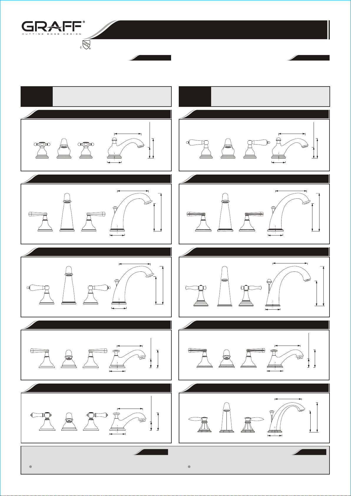
TWO HANDLE WIDESPREAD LAVATORY FAUCET
GRIFO DE DOS MANILLAS DE EXTENSION
This faucet complies with NSF61/9, ASME/ANSI A112.18.1
and CSA B 125 Standards.
Este grifo se encuentra conforme con losestandares de NSF61/9,
de ASME/ANSI A112.18.1 y de CSA B 125.
Dear Customer Estimado Cliente
ENGLISH
Thank you for selecting our product. We are confident we can fully satisfy Muchas gracias por elegir nuestro producto. Estamos seguros que podemos
your expectations by offering you a wide range of technologically advanced
products which directly result from our many years of experience in faucet
and fitting production.
For care, use soft towel with soap and water only! Under no
circumstances should you use any chemicals. For faucets
ATTENTION!
with ORB (oil rubbed bronze) finish please be extra careful
not to damage, scuff or ruin the finish during the installation
and cleaning!
Model
ATLANTIS 1100-C2
Modelo
Installation Instructions l Instrucciones de instalación
~
ESPANOL
satisfacer completamente sus expectativas ofreciéndole una amplia variedad
de productos tecnológicamente avanzados que resultan directamente de
muchos años de experiencia en grifos y su producción apropiada.
Para el cuidado, utilice solamente una toalla suave con jabón y aqua!
Bajo ninguna circunstancia no use productos químicos. Con los grifos
ATENCIÓN!
de acabado ORB (bronce frotado con aceite) hay que tener un cuidado
especial para no dańar, arańar o destruir el acabado durante su
instalación o limpieza!
Model
ATLANTIS 1100-LM2
Modelo
4-13/16" (122mm)
Ø Ø2-17/32" ( 64.5mm)
Model
ELEGANTE 1200-S1
Modelo
5-5/8" (143mm)
Ø Ø2-43/64" ( 67.7mm)
Model
ELEGANTE 1200-LM2
Modelo
5-5/8" (143mm)
Ø Ø2-43/64" ( 67.7mm)
4-13/16" (122mm)
2" (51mm)
3-35/64" (90mm)
Model
Modelo
6-27/32" (174mm)
4-31/32" (126mm)
Model
Modelo
6-27/32" (174mm)
4-31/32" (126mm)
Ø Ø2-17/32" ( 64.5mm)
ELEGANTE 1200-S2
5-5/8" (143mm)
Ø Ø2-43/64" ( 67.7mm)
LAUREN 2400-LM22
6-9/64" (156mm)
Ø Ø2-41/64" ( 67mm)
2" (51mm)
3-35/64" (90mm)
6-27/32" (174mm)
4-31/32" (126mm)
7-3/32" (180mm)
4-31/64" (114mm)
Model
CHANTEAUX 1400-S1
Modelo
4-9/16" (116mm)
Ø Ø2-13/16" ( 71.5mm)
Model
CHANTEAUX 1400-LM15
Modelo
4-9/16" (116mm)
Ø Ø2-13/16" ( 71.5mm)
(41mm)
1-39/64"
3-7/32" (82mm)
(41mm)
1-39/64"
3-7/32" (82mm)
Model
CHANTEAUX 1400-S2
Modelo
4-9/16" (116mm)
Ø Ø2-13/16" ( 71.5mm)
Model
TOPAZ 1900-LM14
Modelo
4-31/32" (126mm)
2-39/64" (66.5mm)
ENGLISH
FLOW RATE INFORMATION INFORMACIÓN DE INTENSIDAD DE FLUJO
Max flow rate 1.2 gpm(4.5 L/min.) at 60psi (4.1 bar) Flujomáximo1.2 gpm(4.5 L/min.)con 60 psi (4.1 bar)
IOG 2009.20
1
(41mm)
1-39/64"
3-7/32" (82mm)
5-15/32" (139mm)
3-15/16" (100mm)
~
ESPANOL
Rev. 8 July 2016
TWO HANDLE WIDESPREAD LAVATORY FAUCET
GRIFO DE DOS MANILLAS DE EXTENSION
This faucet complies with NSF61/9, ASME/ANSI A112.18.1
and CSA B 125 Standards.
Este grifo se encuentra conforme con losestandares de NSF61/9,
de ASME/ANSI A112.18.1 y de CSA B 125.
For easy installation of your Para la instalación fácil de su grifo de la
ENGLISH
GRAFF faucet you will need: GRAFF usted necesitará:
l l
to READ ALL the instructions completely before beginning, LEER TODAS las instrucciones completamente antes de comenzar,
l l
to READ ALL the warnings, care and maintenance information. LEER TODA la información sobre las advertencias,
To complete the project, you should: cuidado y mantenimiento.
l
gather the tools and all the parts you will need, Para terminar el proyecto, usted debe:
l l
prepare the mounting area, recolectar las herramientas y todas las piezas que usted necesitará,
l l
mount the faucet, prepare el área para el montaje,
l l
connect the supply lines, monte el grifo,
l l
finally test and flush the faucet. conecte las líneas de fuente,
You should have the following tools: finalmente pruebe y limpie el grifo con un chorro de agua.
l
flat blade screwdriver,
l
adjustable wrench,
l
channel pliers,
l
hex key (included in the box),
®
l
Teflon tape,
l
plumbers putty or caulking (silicone).
Installation Instructions l Instrucciones de instalación
ESPANOL
l
Usted debe tener las herramientas siguientes:
l
destornillador plano,
l
llave ajustable,
l
alicates acanalados,
l
llave de tuerca hexagonal (incluido en la caja),
l
cinta adhesiva de Teflón ,
l
masilla o silicona.
®
~
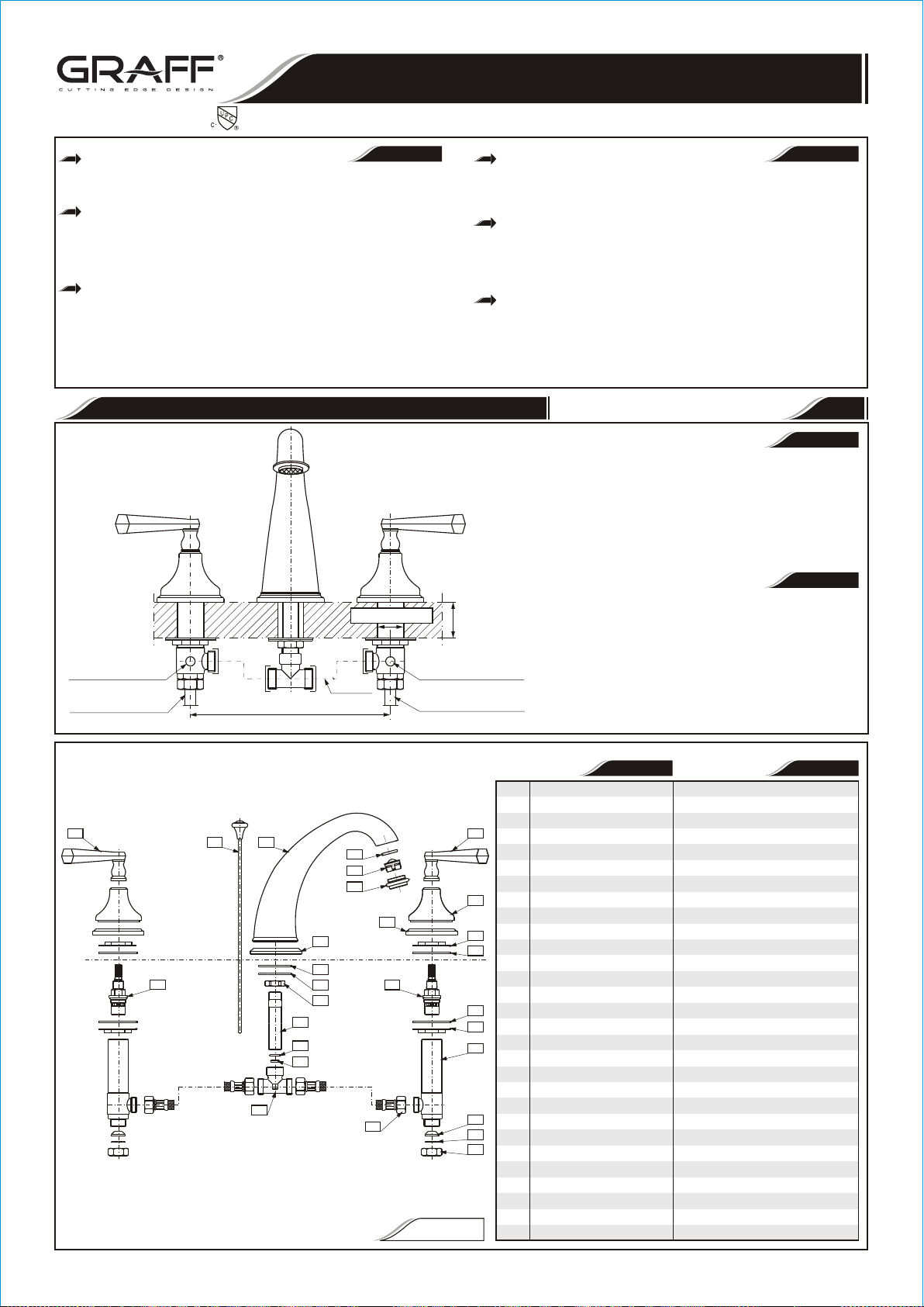
1SET-UP DIAGRAM l DIAGRAMA DE INSTALACIÓN
Hot water valve is marked
with red sticker
La válvula de agua caliente está
marcada con le etiqueta roja
Hot water inlet
Supply tube – 3/8" O.D. (9.5mm)
Entrada de agua caliente
Tuberia - 3/8” O.D. (9.5mm)
7b
11b
3 1
22
8" (203.2 mm)
19
20
21
2a
16
17
18
Flex hose
Flex tuberia
Ømin. 1-1/16" – max. 1-1/2"
Ø
( min. 27mm – max. 38mm)
Ø Ø
4
5
6
2b
11a
23
(max. 35.5 mm)
max. 1-25/64"
Cold water valve is marked
with blue sticker
La válvula de agua fria está
marcada con le etiqueta azul
Cold water inlet
Supply tube – 3/8" O.D. (9.5mm)
Entrada de agua fria
Tuberia - 3/8” O.D. (9.5mm)
7a
8
9
10
10
9
12
13
14
15
FIG. 1
REMOVE OLD FAUCET
l
Turn off the water supplies (hot and cold water).
l
Disconnect supply lines and remove old faucet.
l
Clean the sink surface of putty, dirt., etc.
BEFORE INSTALLING
l
Before installing the faucet, it is good to rinse the supply
pipelines in order to do away with the dirt residue.
l
We recommend installing the filter taps.
QUITE EL GRIFO VIEJO
l
Cierre las llaves de suministro de agua (agua caliente
y fría).
l
Desconecte las líneas de suministro y quite el grifo viejo.
l
Limpie la superficie del fregadero de la masilla,
suciedad, etc.
ANTES DE LA INSTALACIÓN
l
Antes de instalar el grifo, es bueno enjugar las
tuberías suministro para eliminar residuos.
l
Recomendamos el instalar los tapones de filtro.
1
SPOUT
2a
SPOUT BASE
2b
HANDLE BASE
3
LIFT ROD
4
WASHER
5
AERATOR INSERT
6
BODY OF AERATOR
7a
RIGHT HANDLE (cold water)
7b
LEFT HANDLE (hot water)
8
SHROUD
9
FLANGED NUT
10
WASHER
11a
RIGHT CARTRIDGE
(clockwise opening)
11b
LEFT CARTRIDGE
(counterclockwise opening)
12
VALVE
13
CONE GASKET
14
WASHER
15
COUPLING NUT
16
RUBBER PAD
17
STEEL WASHER
18
NUT
19
CONNECTION PIPE
20
SEAL O-RING
21
NOZZLE
22
T-CONNECTION
23
HOSE 13- 3/4" (350mm)
ENGLISH
ENGLISH
~
ESPANOL
~
ESPANOL
GRIFO
BASE DEL GRIFO
BASE DE LA MANILLA
VARILLA ELEVADORA
ARANDELA
ADAPTADOR DEL ANILLO
DIFUSOR
CUERPO DEL AEREADOR
MANILLA DERECHA (agua fría)
MANILLA IZQUIERDA (agua caliente)
CHAPA
TUERCA DE VÁLVULA
ARANDELA
CARTUCHO DERECHO
(abre hacia la derecha)
CARTUCHO IZQUIERDO
abre hacia la
( izquierda)
VÁLVULA
JUNTA DE CONO
ARANDELA
TUERCA
ARANDELA DE CAUCHO
ARANDELA DE METAL
TUERCA
TUBO DE CONECCIÓN
EMPAQUETADURA DE ANILLO
INYECTOR
CONECCIÓN „T”
MANGUERA " (350mm)
13-3/4
IOG 2009.20
2
Rev. 8 July 2016

TWO HANDLE WIDESPREAD LAVATORY FAUCET
GRIFO DE DOS MANILLAS DE EXTENSION
This faucet complies with NSF61/9, ASME/ANSI A112.18.1
and CSA B 125 Standards.
Este grifo se encuentra conforme con losestandares de NSF61/9,
de ASME/ANSI A112.18.1 y de CSA B 125.
ENGLISH
Please check label on valve (Note 1) for identi- Favor de chequiar la etiqueta de la válvula para identificar si es
fication of hot (red sticker) or cold (blue sticker) water. para agua caliente (etiqueta roja) o agua fria (etiqueta azul).
Spin the bottom valve mounting nuts (2) all Haga girar las tuercas de montaje inferiores de la válvula (2)
the way down the valve and remove the top nut and manteniendo la válvula abajo, luego quite la tuerca y las arandelas
washers. Insert valve (1) up through the hole in the superiores. Inserte el cuerpo de válvula (1) por arriba a través del
deck, then drop on the washer (3) and the top agujero en la cubierta, después ponga la arandela (3) y la tuerca de
mounting nut. montaje superior.
Before securing to mounting surface be sure Antes de asegurar a la superficie de montaje asegurarse que el
valve is properly aligned in side hole. Thread on the cuerpo de válvula está alineado correctamente en el agujero. Ajustar
top nut. Adjust the length of valve thread to allow la tuerca superior. Ajuste la longitud de la rosca de la válvula para
the handle base to be properly mounted. permitir que la base de la manilla sea montada correctamente.
Connect hose (23 fig.1) to the outlet Conecte la manguera (23 dis.1) con la conexión del enchufe
connection of the valve. The other end of the hose de la válvula. El otro extremo de la manguera se debe conectar con la
should be connected to T-connection (22 fig.1) after conexión „T” (22 dis.1) después de la instalación del grifo.
spout installation.
Repeat steps for second valve. Make sure that the RED marked
valve is the HOT side (LEFT) and the BLUE marked valve is the
COLD side (RIGHT).
Repita los pasos para el segundo cuerpo de válvula. Asegurarse de que
las valvulas han sido instaladas correctamente, la válvula con etiqueta
roja es para agua caliente (izquierda) y la válvula con etiqueta azul para
agua fria (derecha).
ENGLISH
Test the correct distance of valve thread (see fig.2)
by temporarily placing the handle pieces over the valve.
After you have checked the fitting, remove handle pieces
and tighten the mounting nuts (2 fig.2) with a wrench.
Remount handle pieces: First handle base (1).
Position base over side hole of mounting surface . Second
screw shroud (2) onto valve until against base. Do not
overtighten.
Insert LEFT handle (7b fig.1) on the RED marked
valve and RIGHT handle (7a fig.1) on the BLUE marked
valve.
Test the correct position of handles. The handle
should open and close in a 1/4 turn. Turn handles all the way
on.
NOTE: In case of faucet with cross handles you should turn
cross handles to the left (anticlockwise). Make sure the LEFT
cross handle marked (H) is on the RED marked valve and the
RIGHT cross handle marked (C) is on the BLUE marked
valve.
Attach handles with hex socket screws (4). Use
provided hex key. Utilice la llave de tuercahexagonal proporcionada
1)
If sink is uneven use silicone sealant.
1)
Examine la distancia correcta del hilo de rosca del cuerpo de
válvula (vea dis.2) colocando temporalmente la manilla junto con
las piezas sobre la válvula. Después de que haya comprobado, quite
los piezas moviles de la manilla y ajuste las tuercas de montaje con
una llave.
Reinstalar las piezas moviles de la manilla: Primero - base
de manilla (1). Coloque la base directamente sobre el agujero de la
superficie de montaje . Segundo- enroscar la chapa (2) sobre la
válvula hasta que se encuentre contra base. No apriete demasiado.
Inserta la manilla IZQUIERDA (vea dis.1, punto (7b)) en
la válvula con etiqueta ROJA y la manilla DERECHA (vea dis.1,
punto (7a)) en la válvula con etiqueta AZUL.
Compruebe la posición correcta de manillas. La manilla
debe abrirse y cerrarse en un ¼ devuelta. Gire las manillas.
NOTA: En caso de que de grifos con manillas de cruz girar las
manillas cruzadas a la izquierda (contrario al reloj). Cerciórese de
que la manilla marcada con (H) esta en la valvula con etiqueta ROJA
i a la IZQUIERDA y la manilla marcada con (C) este en la valvula con
etiqueta AZUL y a la DERECHA.
Una las manillas con los tornillos de zócalo con tuerca
hexagonal (4) .
1)
Si el fregadero no esta sellado, use el silicón sellante.
Installation Instructions l Instrucciones de instalación
~
ESPANOL
~
ESPANOL
1)
2
Note 1
Nota 1
Adjust to obtain proper handle height
Ajuste para obtener la altura apropiado
de la manilla
FRONT VIEW - LEFT HANDLE
3
2
1
4
VALVE
VÁLVULA
LAVATORY
LAVATORIO
Vista trasera - manilla izquierdaVista delantera - manilla izquierda
2, 3 ASSEMBLED
2, 3 ENSAMBLADOS
LAVATORY
LAVATORIO
3
1
FIG. 2
BACK VIEW - LEFT HANDLE
SET SCREW
WITH HEX SOCKET
TORNILLO DE PRESIÓN
BASE HEXAGONAL
NOTE: Use Hex Key
(Provided)
NOTE: Para el montaje
use llave hexagonal
FIG. 3a
2 VALVE INSTALLATION l INSTALACIÓN DE LA VÁLVULA
(max 3.55mm)
max. 1-25/64"
3 HANDLES INSTALLATION l INSTALACIÓN de las MANILLAS
For the TOPAZ 1900-LM14 model Para el modelo TOPAZ 1900-LM14
Please check label on valve (NOTE 1) for identification of hot water Por favor, ve el rótulo en la válvula (NOTA 1) para identificar el agua caliente (etiqueta roja) y el
(red sticker), or cold (blue sticker) water. agua fría (etiqueta azul).
Thread flanged nut (2) all the way down on the valve (1) . Baja la tuerca (2) hasta la válvula (1)
Put in washer (3) on the valve (1) until it comes to rest on flanged Pon la arandela (3) sobre la válvula (1) hasta que se apoye sobre la tuerca (2).
nut (2).
Insert the valve (1) up through the the hole in the deck. Thread
onto the valve the handle base (4),
Make sure that the o-ring (5) is correctly positioned in the groove in
the bottom of the base (4).
Then place the handle (6) on the splines of the valve head, check (4) en la posición indicada en la fig. 3b: así alcanzamos el efecto estético deseado.
that the distance 'H' is sufficient to allow elements (4) and (6) to fit
properly; if not, remove handle (6), and adjust the distance 'H' with the
flange nut (2) and handle base (4). Put the handle base (4) in the
position shown on the fig. 3b;the desired aesthetical effect will be achieved
then.
After choosing the appropriate distance 'H' replace the handle (6)
onto the spline of the valve head (1). Turn the left handle all the way to
the left (in case of the right handle - all the way to the right) until it is in the
OFF position. If the position of a handle is different then the one shown in
the fig. 3c for ON position, take the handle off the spline of the valve and
put it on correctly again. Rotate the handle to the OFF position. Screw in
the attaching screw (7) with the hex key (included with the faucet).
ENGLISH
Mete la válvula (1) a través del agujero. Mete la base del mango (4) sobre la válvula.
Asegúrate de que el anillo (5) está correctamente colocado en la ranura en el fondo de la base (4).
Entonces coloca el mango (6) sobre los salientes de la cabeza de la válvula, controla si la distancia 'H'
es suficiente para que los elementos (4) i (6) estén bien unidos; si la distancia es inadecuada, quita el
mango (6) y ajusta la distancia 'H' con la tuerca (2) y la base del mango (4). Coloca la base del mango
Al ajustar la distancia 'H' adecuada, coloca de nuevo el mango (6) sobre el saliente de la cabeza de la
válvula (1). Gira el mango izquierdo hacia la izquierda (y el mango derecho hacia la derecha) hasta que
alcance la posición OFF. Si la posición del mango es diferente de la indicada en la fig. 3c para la posición ON,
saca el mango del saliente de la válvula y colócalo correctamente de nuevo. Gira el mango hasta la posición
OFF. Atornilla el tornillo (7) con la llave hexagonal (incluida con el grifo).
6
4
6
Top view / Vista desde arriba.
6
H
3
2
1
Note 1
Nota 1
IOG 2009.20
7
4
5
4
Adjust to obtain proper handle height
Ajusta para obtener la altura
adecuada del mango.
4
OFF OFF
c
o
u
n
t
e
r
c
l
o
i
z
c
q
k
w
u
i
i
e
s
r
d
a
FIG. 3b
3
Make sure that the edges of the handle base (4)
are aligned with the edges of the handle (6).
Asegúrate que los cantos de la base del mango (4)
están alineados con los cantos del mango (6).
e
o
p
e
Suggested positioning of
handle bases and handles
n
i
n
g
Posición sugerida de las
bases y de los mangos
ON
~
ESPANOL
g
n
i
n
e
p
a
o
h
e
c
s
i
e
r
w
e
k
c
d
o
l
c
ON
FIG. 3c
Rev. 8 July 2016

TWO HANDLE WIDESPREAD LAVATORY FAUCET
GRIFO DE DOS MANILLAS DE EXTENSION
This faucet complies with NSF61/9, ASME/ANSI A112.18.1
and CSA B 125 Standards.
Este grifo se encuentra conforme con losestandares de NSF61/9,
de ASME/ANSI A112.18.1 y de CSA B 125.
Installation Instructions l Instrucciones de instalación
4 SPOUT INSTALLATION l INSTALACIÓN DEL GRIFO
ENGLISH
Insert spout base (7) and center over side hole of mounting surface. Insert spout shank through the
central hole in the deck.
Position spout (8) onto spout base (7). Place rubber washer (6), metal washer (5) and mounting
nut (4) over the shank and tighten the underside of the deck.
Insert nozzle (2) and seal o-ring (3) into T-connection (1).
Screw on the T-connection (1) onto spout shank as shown in fig. 4 firmly but do not overtighten.
Inserte la base del grifo (7) y centre con el agujero de la superficie de montaje. Inserte el tubo de
conección a través del agujero central en la cubierta.
Coloque la varilla elevadora (8) sobre la base del grifo (7). Coloque la arandela de goma (6), la
arandela del metal (5) y la tuerca de montaje (4) y apriete contra la superficie inferior.
Inserte el inyector (2) y la empaquetadura de anillo (3) en la conección „T” (1).
Ajuste la conección „T” (1) sobre el tubo de conección según lo demostrado en la dis. 4 firmemente
pero no apriete demasiado.
1
2
3
4
5
6
7
8
9
10
1
PROTECTIVE CAP
2
DRAIN PLUG
3
DRAIN COLLAR
4
COLLAR GASKET
5
UNDER-BOWL GASKET
6
WASHER
7
FLANGED NUT
8
WASHER
9
DRAIN BODY
10
DISCHARGE PIPE
11
SEALING WASHER
12
BALL ROD
13
BALL ROD NUT
14
ADJUSTMENT PLATE
15
CLIP
16
SCREW
11 12 13
ENGLISH
TAPA PROTECTORA
TAPÓN DE DRENAJE
COLLAR DE DRENAJE
EMPAQUETADURA SUPERIOR
EMPAQUETADURA INFERIOR
ARANDELA DE MONTAJE
TUERCA DE MONTAJE
ARANDELA DE TUBO
CUERPO DE DRENAJE
PIPA DE DESCARGA
ARANDELA SELLADORA
VARILLA DE BOLA
TUERCA DEL PIVOTE
PLATO DE AJUSTAMIENTO
BROCHE
TORNILLO
LIFT ROD
(fig.1, item 3 )
Varilla elevadora
(3 fig. 1)
14
15
FIG. 5
~
ESPANOL
16
Dismantle the drain assembly to the parts shown on fig. 5.
Insert collar gasket (4) and drain collar (3) into drain hole of a lavatory. From
underneath the lavatory slip under-bowl gasket (5) into drain collar (3), washer (6) and
flanged nut (7).
Position under-bowl gasket (5) correctly under the lavatory and screw flanged nut (7)
firmly but do not overtighten.
Make sure washer (8) is inside drain body (9) and screw drain body (9) onto drain
collar (3) hand tighten only.
Pay attention to align the drain body (9) so that the horizontal hole of drain body will be
in the same plane as a lift rod (3 fig.1). Tighten drain body (9) onto drain collar (3) and
tighten the flanged nut (7).
Insert drain plug (2) into drain collar (3).
Remove clip (15) from ball rod (12); undo a ball rod nut (13) from body, take out
sealing washer (11) from a nut and push the nut forward over ball rod (12) from the longer
end with the thread facing a ball.
Insert the sealing washer (11) and the ball rod (12) into a side hole of drain body (9).
Make sure that the rod ending goes under the plug screw head.
Tighten ball rod nut (13) making sure that the ball rod seat (11) and ball rod (12) are
properly installed.
Add Teflon tape to tail tube (10), and mount tail tube to drain body (9).
Lift the drain plug (2) to an open position, by lowering the horizontal ball rod (12) down.
Insert lift rod (3 fig.1) down through spout (1 fig.1) and top of lift rod strap (14).
Adjust to proper height and tighten screw (16).
Choose the position of horizontal ball rod (12) in one of the holes in lift rod strap (14).
Insert horizontal ball rod (12) through one arm of spring clip (15) and lift rod strap (14) and
then second arm of spring clip (15).
Try if a drain plug (2) closes the drain by pulling the lift rod. If not, make corrections of
position of lift rod strap (14) and horizontal ball rod (12).
Desmontar las piezas del drenaje según lo demostrado en la dis. 5.
Inserte la empaquetadura superior (4) y el tapon del drenaje (3) en el agujero del
drenaje de un servicio. Colaque por debajo del lavatorio la empaquetadura inferior (5) en el
collar del drenaje (3), la arandela (6) y tuerca de montaje (7)
Coloque la empaquetadura inferior (5) correctamente debajo del servicio y entornille
a tuerca de montaje (7) firmemente pero no apriete demasiado.
Cerciorese de que la arandela de tubo (8) este en el cuerpo del drenaje (9) y entornille
el cuerpo del drenaje (9) en el collar del drenaje (3) apriete solamente con la mano
Preste atención en alinear el cuerpo del drenaje (9) de modo que el agujero horizontal
del cuerpo del drenaje esté en el mismo plano que la varilla elevadora (dis.1, elem. 3). Apriete
el cuerpo del drenaje (9) sobre el collar del drenaje (3) y apriete la tuerca de montaje (7).
Inserte el tapón de drenaje (2) en el collar del drenaje (3).
Quite el clip de la abrazadera de muelle (15) del varilla de bola (12); retire la tuerca
del pivote (13) del cuerpo, tome hacia fuera el arandela selladora (11) a lo largo del varilla de
bola (12) del extremo más.
Inserte el arandela selladora (11) y el varilla de bola (12) en un agujero lateral del
cuerpo del drenaje (9). Asegúrese de que el extremo de la barra va debajo de la cabeza del tornillo
del tapón.
Ajuste la tuerca del pivote (13) serciorandose de que el arandela selladora de la barra (11)
y el varilla de bola (12) este instalado correctamente.
Enrrollar la cinta de teflon para asegurar el pipa de descarga (10), monte colillo al
cuerpo del drenaje (9).
Levante el tapón de renaje (2) a la posición de abierto, moviendo el varilla de bola (12)
hacia abajo.
Inserte la varilla elevadora (dis.1, elem. 3) por el agujero en el grifo (dis. 1, elem.1)
y inserte el plato de ajustamiento (14). Ajuste a la altura apropiada y apriete el tornillo (16).
Elija la posición del varilla de bola (12) en uno de los agujeros del plato de ajustamiento (14).
El varilla de bola (12) a través de la broche (15) y levante el plato de ajustamiento (14) y despues el
segundo brazo de la broche (15).
Intente cerrar con el tapón de drenaje (2) tirando de la varilla de elevación. Si no es
posible, haga las correcciones de la posición del plato de ajustamiento (14) y de la barra
horizontal del el varilla de bola (12).
~
ESPANOL
9
8
7
4
3
2
Lavatory
LAVATORIO
6
5
1
FIG. 4
5DRAIN ASSEMBLY INSTALLATION l INSTALACIÓN DEL DRENAJE
ENGLISH
~
ESPANOL
d
IOG 2009.20
4
Rev. 8 July 2016

TWO HANDLE WIDESPREAD LAVATORY FAUCET
GRIFO DE DOS MANILLAS DE EXTENSION
This faucet complies with NSF61/9, ASME/ANSI A112.18.1
and CSA B 125 Standards.
Este grifo se encuentra conforme con losestandares de NSF61/9,
de ASME/ANSI A112.18.1 y de CSA B 125.
MAKE CONNECTIONS TO WATER LINES l CONECCION A LAS FUENTES DE AGUA
See fig. „Set-up Diagram” and fig. 1 Vea dis. „Diagrama de instalación” y dis. 1
Use mounting set to 3/8” copper tubes consisting of cone gaskets Use un completo de montaje para tuberias de Cu de 3/8” que consisten
(13) metal washers (14) and coupling nuts (15). en empaquetaduras (13) las arandelas de metal (14) y uniones (15).
Use adjustable wrench when tightening. Do not overtighten. Utilice llaves ajustables cunado necesite ajustar alguna pieza. No
ENGLISH
Installation Instructions l Instrucciones de instalación
ajuste demasiado.
6
~
ESPANOL
AFTER INSTALLATION BEFORE USE l DESPUÉS DE LA INSTALACIÓN - ANTES DEL USO
See fig. 1 Vea dis.1
Remove body of aerator (6), aerator insert (5) and washer (4) and Quite el cuerpo del aerador (6), el adaptador del aerador (5) y la
turn faucet lever handles all the way on. In case of faucet with cross arandela (4) de la vuelta las manillas del grifo de tal manera que este
handles you should turn cross handles to the left (counterclockwise). todo el tiempo abierto. En caso de grifo con manijas cruzadas dé la
Open the hot and cold water supply valves and flush water lines for vuelta a las manijas a la izquierda (contrario al reloj).
15 seconds . Abre las válvulas de agua caliente y fría y deje enjuagar las tuberias
Turn the hot and cold handles off. por 15 segundos .
Check all connections at arrows for leaks. Re-tighten if necessary, Cierre las manillas de agua fria y caliente.
but do not overtighten. Compruebe todas las conexiones para saber si hay fuga de agua. Vuelva
Next replace washer (4), aerator insert (5) and body of aerator a apretar en caso de necesidad, pero no apriete demasiado.
(6). Hand tighten only. Seguidamente substituya la arandela (4), el adaptador del aerador (5)
1)
IMPORTANT: This flushes away any debris that could cause damage to internal parts.
CONGRATULATIONS! Your installation is now complete!
1)
ENGLISH
1)
y cuerpo del aerador (6). Ajuste solamente con la mano.
1)
IMPORTANTE: Esto limpia las tuberias con un chorro de agua de todo residuo que podría causar
FELICIDADES! Su instalación esta completa ahora!
dańo a las piezas internas.
ESPANOL
CARE AND MAINTENANCE l CUIDADO Y MANTENIMIENTO
ENGLISH
Your Graff faucet is designed and engineered in accordance with Su grifo de la Graff esta diseńado y dirigido acuerdo con los
the highest quality and performance standards. Be sure not to estándares de funcionamiento y calidad más altos. Este seguro no
damage the finish during installation. Care should be given to the dańar las terminaciones del grifo durante la instalación. Cuide el
cleaning of this product. Although its finish is extremely durable, it producto manteniendolo siempre limpio. Aunque su acabado es
can be damaged by harsh abrasives or polish. Never use extremadamente durable, puede ser dańado por los abrasivos o
abrasive cleaners, acids, solvents, etc. to clean any Graff pulientes ásperos. Nunca utilice limpiadores abrasivos, ácidos,
product. To clean, simply wipe gently with a damp cloth and solventes, el etc. para limpiar cualquier producto de la Graff.
blot dry with a soft towel. Para limpiar, simplemente use un pańo húmedo y seque con
una toalla suave.
ESPANOL
7
~
8
~
WARRANTY l GARANTÍA
ENGLISH
Warranty conditions and warranty registration card are outlined on a Las condiciones de la garantía y la tarjeta del registro de la garantía
separate sheet. se encuentran en una pagina separada.
All dimensions and drawings are for reference only. For details, please refer to actual products.
Todas las dimensiones y dibujos sirven únicamente de referencia. Para consultar detalles, ver los productos.
IOG 2009.20
5
~
ESPANOL
Rev. 8 July 2016
 Loading...