

Page 1

N720 DECT IP
Site Planning and Measurement Guide
Multicell System
VoIPon www.voipon.co.uk sales@voipon.co.uk Tel: +44 (0)1245 808195 Fax: +44 (0)1245 808299
Page 2

VoIPon www.voipon.co.uk sales@voipon.co.uk Tel: +44 (0)1245 808195 Fax: +44 (0)1245 808299
Page 3

1
Ta
bl e o f Contents
Table of Contents
S
afety precautions . . . . . . . . . . . . . . . . . . . . . . . . . . . . . . . . . . . . . . . . . . . . . . . . . 2
Introduction . . . . . . . . . . . . . . . . . . . . . . . . . . . . . . . . . . . . . . . . . . . . . . . . . . . . . . . 3
The Gigaset N720 DECT IP Multicell System . . . . . . . . . . . . . . . . . . . . . . . . . . . . . . . . . . . . 3
Criteria for an optimum DECT wireless network . . . . . . . . . . . . . . . . . . . . . . . . . . . . . . . . 5
How to proceed . . . . . . . . . . . . . . . . . . . . . . . . . . . . . . . . . . . . . . . . . . . . . . . . . . . . . . . . . . . . . . 8
Projecting the DECT network . . . . . . . . . . . . . . . . . . . . . . . . . . . . . . . . . . . . . . . 9
Determining the requirements for the telephone network . . . . . . . . . . . . . . . . . . . . . 9
Conditions for the positioning of the base stations . . . . . . . . . . . . . . . . . . . . . . . . . . . . 10
Preliminary identification of the positions of the base stations . . . . . . . . . . . . . . . . . 18
Taking measurements . . . . . . . . . . . . . . . . . . . . . . . . . . . . . . . . . . . . . . . . . . . 20
Defining limit values . . . . . . . . . . . . . . . . . . . . . . . . . . . . . . . . . . . . . . . . . . . . . . . . . . . . . . . . . 21
Measuring the wireless range of the planned base stations . . . . . . . . . . . . . . . . . . . . 24
Evaluating measurements . . . . . . . . . . . . . . . . . . . . . . . . . . . . . . . . . . . . . . . . . . . . . . . . . . . . 28
Working with the Gigaset N720 SPK PRO . . . . . . . . . . . . . . . . . . . . . . . . . . 29
Checking the package contents . . . . . . . . . . . . . . . . . . . . . . . . . . . . . . . . . . . . . . . . . . . . . . 29
Further recommended accessories . . . . . . . . . . . . . . . . . . . . . . . . . . . . . . . . . . . . . . . . . . . 30
Before you begin . . . . . . . . . . . . . . . . . . . . . . . . . . . . . . . . . . . . . . . . . . . . . . . . . . . . . . . . . . . . 31
Setting up the measuring base station . . . . . . . . . . . . . . . . . . . . . . . . . . . . . . . . . . . . . . . . 31
Starting up the measuring handset . . . . . . . . . . . . . . . . . . . . . . . . . . . . . . . . . . . . . . . . . . . 35
Operating the measuring handset . . . . . . . . . . . . . . . . . . . . . . . . . . . . . . . . . . . . . . . . . . . . 37
DECT installations in special environments . . . . . . . . . . . . . . . . . . . . . . . . 41
Customer care and help . . . . . . . . . . . . . . . . . . . . . . . . . . . . . . . . . . . . . . . . . . 43
Questions and answers . . . . . . . . . . . . . . . . . . . . . . . . . . . . . . . . . . . . . . . . . . . . . . . . . . . . . . 43
Environment . . . . . . . . . . . . . . . . . . . . . . . . . . . . . . . . . . . . . . . . . . . . . . . . . . . . 43
Our environmental mission statement . . . . . . . . . . . . . . . . . . . . . . . . . . . . . . . . . . . . . . . . 43
Environmental management system . . . . . . . . . . . . . . . . . . . . . . . . . . . . . . . . . . . . . . . . . 43
Disposal . . . . . . . . . . . . . . . . . . . . . . . . . . . . . . . . . . . . . . . . . . . . . . . . . . . . . . . . . . . . . . . . . . . . . 43
Appendix . . . . . . . . . . . . . . . . . . . . . . . . . . . . . . . . . . . . . . . . . . . . . . . . . . . . . . . 44
Care . . . . . . . . . . . . . . . . . . . . . . . . . . . . . . . . . . . . . . . . . . . . . . . . . . . . . . . . . . . . . . . . . . . . . . . . . 44
Contact with liquid . . . . . . . . . . . . . . . . . . . . . . . . . . . . . . . . . . . . . . . . . . . . . . . . . . . . . . . . . . 44
Authorisation . . . . . . . . . . . . . . . . . . . . . . . . . . . . . . . . . . . . . . . . . . . . . . . . . . . . . . . . . . . . . . . . 44
Specifications . . . . . . . . . . . . . . . . . . . . . . . . . . . . . . . . . . . . . . . . . . . . . . . . . . . . . . . . . . . . . . . . 45
Accessories . . . . . . . . . . . . . . . . . . . . . . . . . . . . . . . . . . . . . . . . . . . . . . . . . . . . . . 46
Glossary . . . . . . . . . . . . . . . . . . . . . . . . . . . . . . . . . . . . . . . . . . . . . . . . . . . . . . . . 47
Index . . . . . . . . . . . . . . . . . . . . . . . . . . . . . . . . . . . . . . . . . . . . . . . . . . . . . . . . . . . 51
VoIPon www.voipon.co.uk sales@voipon.co.uk Tel: +44 (0)1245 808195 Fax: +44 (0)1245 808299
Page 4
2
Sa
fety precautions
Safety precautions
Warning
Read the safety precautions and the user guide before use.
Use only the power adapter supplied.
Use only the recommended, rechargeable batteries (
£
page 45) as this could
otherwise result in significant health risks and personal injury.
Using your telephone may affect nearby medical equipment. Be aware of the
technical conditions in your specific location e.g., doctor's surgery.
Do not hold the rear of the handset to your ear when it is ringing or when
speaker mode is activated, otherwise you risk serious and permanent damage
to your hearing.
Your Gigaset is compatible with the majority of digital hearing aids on the market. However, perfect function with all hearing aids cannot be guaranteed.
The handset may cause an unpleasant humming or whistling noise in hearing
aids or cause them to overload. If you require assistance, please contact the
hearing aid supplier.
Do not install the base station and charger in bathrooms or shower rooms.
The base station is not splashproof.
Do not use the devices in environments with a potential explosion hazard, for
example, paint shops.
If you give your phone to a third party, make sure you also give them the
user guide.
Remove faulty devices from use or have them repaired by our Service team, as
these could interfere with other wireless services.
VoIPon www.voipon.co.uk sales@voipon.co.uk Tel: +44 (0)1245 808195 Fax: +44 (0)1245 808299
Page 5
3
I
ntroduction
Introduction
This document explains the preparations necessary to install a multi-cell DECT network
and take measurements for the optimum positioning of the base stations. It also provides
technical and practical background information.
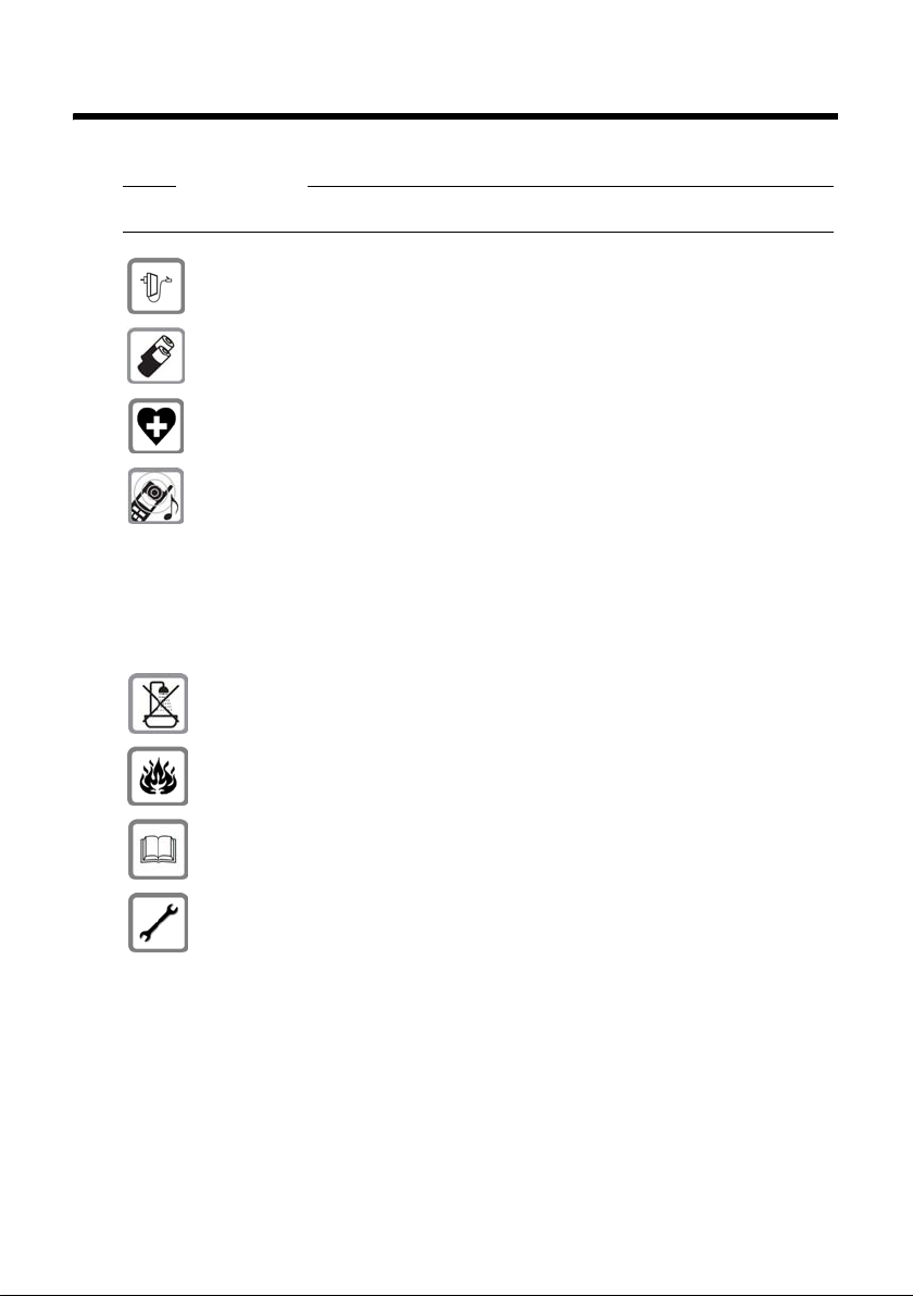
The Gigaset N720 DECT IP Multicell System
The Gigaset N720 DECT IP Multicell System is a DECT multi-cell system for connecting
DECT base stations to a VoIP PABX. It combines the options of IP telephony with the use
of DECT telephones.
The following illustration shows the components of the Gigaset N720 DECT IP Multicell
System and how they are embedded in the IP telephone environment:
u DECT Manager Gigaset N720 DM PRO
Central management station for managing the DECT network. One DECT Manager
must be used for each installation.
– Manages up to 20 DECT base stations
– Manages up to 100 handsets on multi-cell systems
– Enables division into subnets (
Cluster formation)
–
Forms the interface to an IP PABX (e.g., Gigaset T500 PRO or Gigaset T300 PRO)
A Web user interface is available for configuring and administering the DECT network.
u Gigaset N720 IP PRO DECT base stations
– These are the cells of the DECT telephone network.
– Each base station can manage up to eight calls simultaneously (see the
Capacity
section
£ page 6)
PAB X
VoIP, ISDN, analogue
DECT
base stations
Gigaset N720
IP PRO
DECT Manager
Gigaset N720 DM PRO
LAN
Configuration via
Web interface
Handover & roaming
Gigaset IP PRO telephones
e.g., Gigaset DE900 IP PRO
Gigaset
handsets
VoIPon www.voipon.co.uk sales@voipon.co.uk Tel: +44 (0)1245 808195 Fax: +44 (0)1245 808299
Page 6
4
I
ntroduction
u Gigas
et handsets
– Up to 100 handsets can be connected and up to 30 calls conducted simultaneously.
The following handsets are recommended: Gigaset SL610H, SL400H, S810H, E49H.
– Subscribers can accept or initiate calls in all DECT cells with their handset (Roam-
ing
), and can also switch between the DECT cells during a call (Handover).
u PA BX
You can connect your DECT telephone system to a PABX for VoIP, ISDN or analogue
telephony, e.g., a Gigaset T500 PRO.
– Establishes the connection to a public telephone network for analogue, VoIP or
ISDN calls.
– Enables central management of telephone connections, directories, network mail-
boxes, etc.
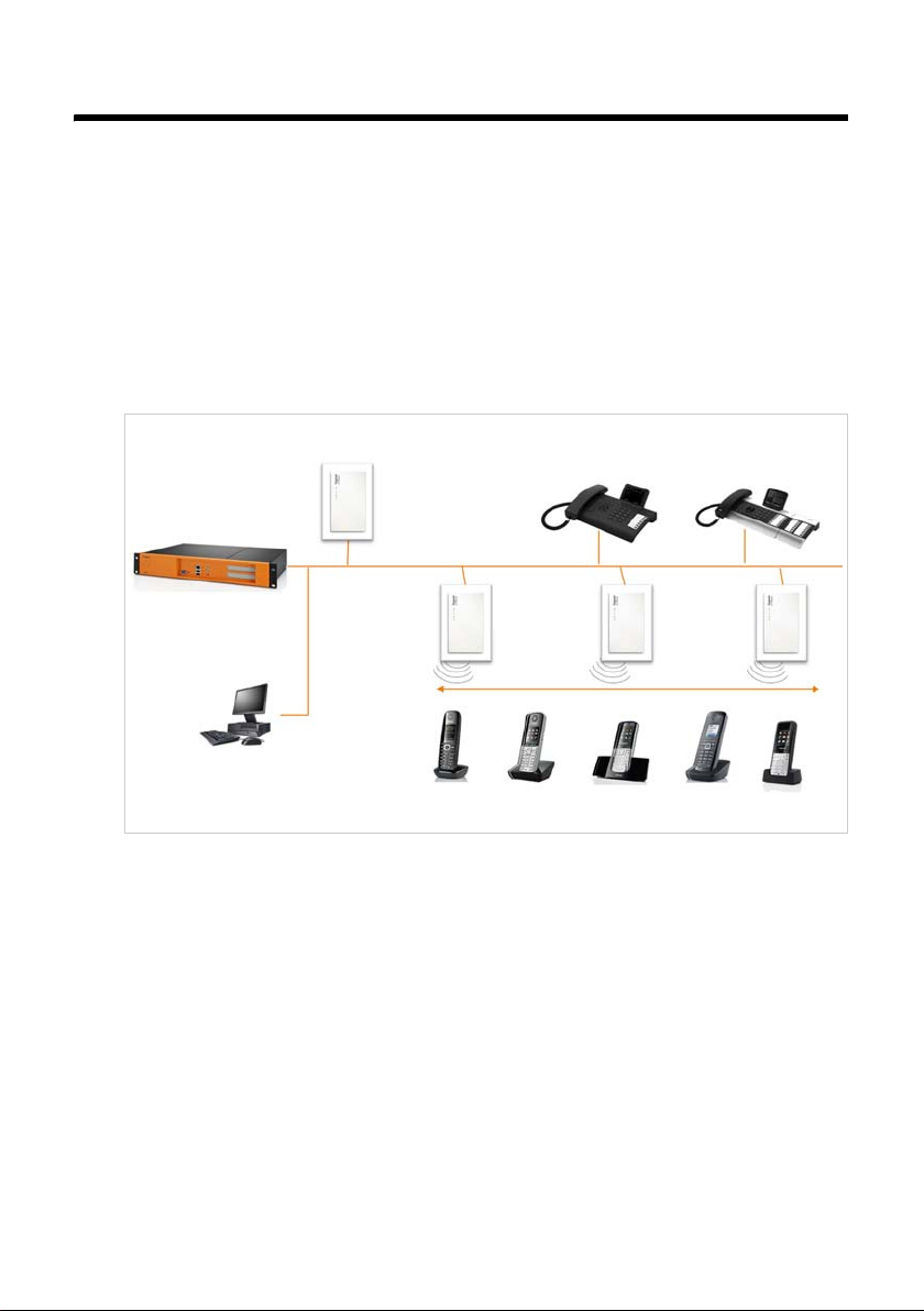
u Cluster formation with Gigaset N720 DECT IP Multicell System
You can divide DECT base stations that you have installed at your location into several
independent groups, i.e., clusters, and manage them using one Gigaset N720 DM PRO
DECT Manager.
The DECT Manager is connected to the base stations and the PABX via the local network and is therefore not dependent on DECT ranges. This means that you can install
separate DECT islands at your location but manage them centrally, i.e., they have
access to the centrally configured IP connections, directories, etc.
For further information about the options provided by the Gigaset N720 DECT IP Multicell
System, and about installing, configuring and operating the Gigaset devices mentioned,
see the relevant user guide. These are provided on the product CD or on the Internet at
www.gigaset.com/pro
.
Gigaset offers the Gigaset N720 SPK PRO (Site Planning Kit) to help you with measuring
the wireless coverage and quality of your DECT network. For information on setting up
and using the Gigaset measuring equipment, see the
Working with the Gigaset N720
SPK PRO
chapter
£ page 29.
LAN
DECT
Manager
Cluster 1
Cluster 2
VoIPon www.voipon.co.uk sales@voipon.co.uk Tel: +44 (0)1245 808195 Fax: +44 (0)1245 808299
Page 7
5
I
ntroduction
Criteria for an optimum DEC
T wireless network
A carefully planned DECT wireless network with adequate coverage is the prerequisite for
operating a telephone system that offers good call quality and sufficient call options for
all subscribers in all buildings and areas belonging to the PABX.
It is difficult to assess the technical wireless conditions of a DECT installation in advance
as they are influenced by many environmental factors. Therefore, the specific circumstances on-site must be determined by taking measurements. This produces a reliable
statement about the material required as well as the locations of the wireless units.
Various aspects need to be taken into consideration when planning a DECT wireless network. The following requirements must be considered when deciding how many base
stations are required and where they should be placed:
u Sufficient DECT wireless coverage of the entire site so that every subscriber can be
reached.
u Sufficient wireless channels (DECT bandwidth), in particular in "hotspots", to avoid
capacity bottlenecks.
u Sufficient overlap of cells to enable synchronisation of the base stations and to guar-
antee freedom of movement for subscribers when making calls.
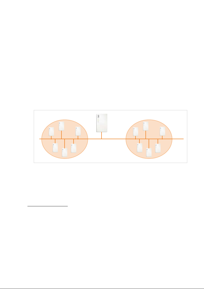
Wireless coverage
The selection of locations where the base stations are to be installed should guarantee
optimum wireless coverage and enable cost-effective wiring.
Optimum wireless coverage is achieved if the required reception quality is delivered at all
points of the wireless network. If costs need to be considered, this should be done with a
minimum number of DECT base stations.
To ensure an interference-free switch of call connections from one cell to another (handover), there must be an area where good reception is ensured for both base stations. To
achieve this, a minimum quality for reception must be defined.
Wireless cell
Base station
Overlap
VoIPon www.voipon.co.uk sales@voipon.co.uk Tel: +44 (0)1245 808195 Fax: +44 (0)1245 808299
Page 8
6
I
ntroduction
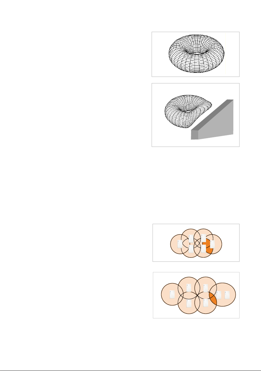
Signal transmission
The id
eal signal transmission of a base station is
shaped like a ring, i.e., so that the registered
handsets can be the same distance away from
the base station in all directions without the
wireless signal being interrupted.
However, the transmission is influenced by various environmental conditions. For example,
obstacles such as walls or metal doors can
impede the wireless signals or interfere with
their even transmission.
You should investigate the actual conditions
that the planned wireless network will be subjected to by measuring the signal transmission
of the measuring base station at appropriate
positions.
Capacity
The capacity of the cells must be large enough to guarantee that the subscribers can be
reached in high-density traffic. A cell is at full capacity when the number of connections
required for each base station is larger than the number of possible connections.
A Gigaset N720 IP PRO can manage eight connections simultaneously when operated in
narrowband mode (
£
Narrowband mode, page 49). In broadband mode, four simulta-
neo
us connections are possible (
£Broadband mode, page 47).
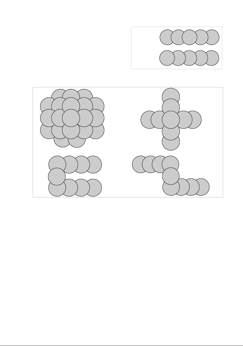
There are two options for increasing the capacity:
u Reducing the distance between the base stations.
This means that the cells overlap more, giving
the subscriber access to the base stations of
the neighbouring cells. This results in a more
even wireless quality. However, this can result
in considerable installation costs for an existing system.
u Installing parallel base stations.
The cell size remains generally constant but
the number of possible connections increases.
Installing the base stations close to one
another means that the additional assembly
costs are low, but a minimum distance must be
observed between the base stations (
£
Te ch -
nical conditions, page 11).
To keep the costs for the devices and for the
installation and maintenance low, as few base stations as possible should be installed.
VoIPon www.voipon.co.uk sales@voipon.co.uk Tel: +44 (0)1245 808195 Fax: +44 (0)1245 808299
Page 9
7
I
ntroduction
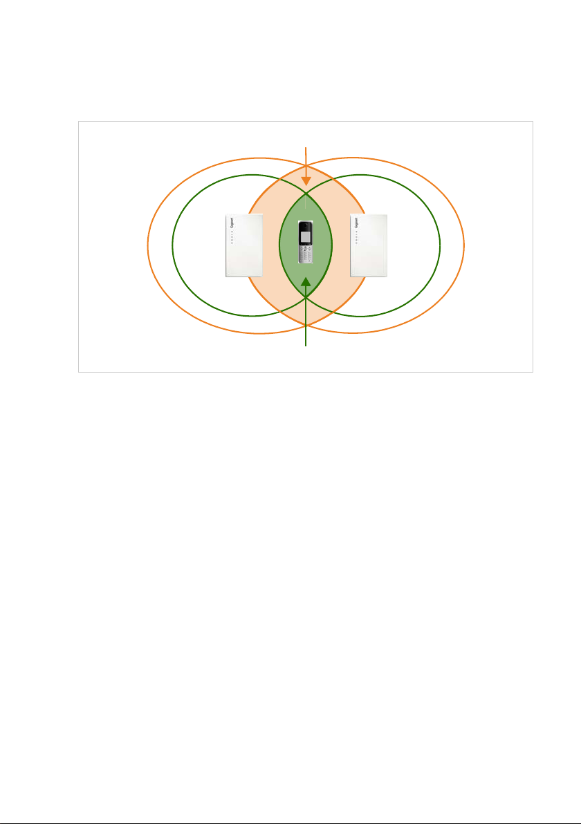
Overlapping and synchronising
F
or interference-free cooperation in a multi-cell DECT network, the base stations must
synchronise. In order to synchronise the base stations and ensure a smooth handover, the
cells must overlap.
A sufficient number of large overlapping zones between neighbouring cells must be
ensured. To achieve synchronisation, the reception must be of sufficient quality to ensure
that the base stations can receive one another securely. For a handover, a handset must
have a connection of sufficient quality to both base stations. You will find information
about possible interferences in the
Defining limit values section
£ page 21.
The more densely the base stations are installed, the greater the overlap. Here, a compromise must be found between keeping the area relatively open and installing the lowest
possible number of base stations.
Handover overlap
Synchronisation overlap
VoIPon www.voipon.co.uk sales@voipon.co.uk Tel: +44 (0)1245 808195 Fax: +44 (0)1245 808299
Page 10

8
I
ntroduction
How to proceed
U
se the following guide to quickly locate the most important topics.
If you have any questions about using your measuring devices, please contact
our Customer care team (
£ page 43).
Information on ... ... is located here.
Determining the requirements for the telephone network
Determine the requirements for the telephone network and collect
information about the environmental conditions for the planned
DECT wireless network.
page 9
Creating an installation plan
Create a building plan and enter the planned DECT base stations in
this plan. You should take account of the general conditions deter-
mined and the technical requirements of DECT telephony in the
process.
page 18
Taking measurements
Use the installation plan to take measurements and adapt the instal-
lation plan to your measurement results.
page 20
Working with the Gigaset measuring equipment
Have you purchased the Gigaset N720 SPK PRO (Site Planning Kit)?
Here you can read about how to set up the measuring equipment
and how to use it to take measurements.
page 29
Special environments
Do you want to set up your DECT network in a difficult environment?
Helpful information and tips are available here.
page 41
g
g
g
g
g
VoIPon www.voipon.co.uk sales@voipon.co.uk Tel: +44 (0)1245 808195 Fax: +44 (0)1245 808299
Page 11

9
P
rojecting the DECT network
Projecting the DECT network
There are a number of conditions to be considered when setting up a DECT network. They
affect the subscribers' requirements for the telephone system as well as the technical
requirements for the DECT wireless network. These conditions must therefore be
recorded and evaluated in a projection phase.
To project your DECT network, proceed as follows:
u First determine the requirements for the telephone network and establish the environ-
mental conditions for the DECT wireless network.
u Define how many base stations are required and their probable optimum positioning.
Create an installation plan for the base stations.
u Take measurements to check whether the positioning of the base stations at the
assumed positions meets the requirements and whether the reception and sound
quality is sufficient everywhere. If necessary, change the installation plan to optimise
the DECT wireless network.
Determining the requirements for the telephone network
Clarify the following questions to determine the requirements for the telephone network:
Subscribers and subscriber behaviour
u How many employees should be able to make calls and how many subscribers should
be able to make calls simultaneously?
– How many handsets are required?
– How many base stations are required?
u Where should telephone calls be possible?
– In which buildings (floors, stairwell, basement, underground garage)?
– Outdoors (on footpaths, on the car park)?
For more information about this, please refer to the information in the section
Out-
side
area
,
£
page 42.
– How are the handsets distributed from a location perspective?
u How many calls will be made?
– What is the telephony behaviour of the subscribers? How long is the average call?
– Where are the hotspots, i.e., where do a lot of subscribers gather simultaneously
(open-plan office, canteen, cafeteria, etc.)?
– Where are telephone conferences held? How many telephone conferences are held
and how long are these?
Environmental conditions
u Where is the site that is to be covered by the DECT wireless network?
– Total area of the required wireless coverage
– Position and dimensions of the rooms, building plan
– Number of floors, basements
¤ Request a building plan that shows positions and dimensions and that can be used
to document the subsequent installation planning.
VoIPon www.voipon.co.uk sales@voipon.co.uk Tel: +44 (0)1245 808195 Fax: +44 (0)1245 808299
Page 12

10
P
rojecting the DECT network
u What is
the basic structure of the building?
– What materials and construction types have been used for the buildings?
– What type of windows does the building have (e.g., tinted glass)?
– What construction changes are expected in the near future?
u What disruptive influences can be identified?
– What are the walls made of (concrete, brick, etc.)?
– Where are the lifts, fire doors, etc. located?
– What furniture and devices are present or planned?
– Are there other wireless sources in the vicinity?
For detailed information on material characteristics and interference factors,
£
page 16.
C
onditions for the positioning of the base stations
Features of the Gigaset N720 DECT IP Multicell System
u A Gigaset N720 DM PRO DECT Manager can manage a maximum of 20 base stations
and 100 handsets.
u The DEC T network can be divided into clusters; i.e., you can install several independent
DECT islands that are managed centrally by a DECT Manager.
u A Gigaset N720 IP PRO base station can establish a maximum of eight connections
simultaneously (four connections in Broadband mode).
This must be taken into consideration in the capacity calculations (
£
page 13).
Technical conditions
The following values can be used as a guide for the planning. They are values that are
influenced by environmental conditions and that should therefore be checked via measurements.
u The wireless range of a DECT base station for handsets is (guide values)
– Up to 50 m indoors
– Up to 300 m outdoors
These guide values do not apply to the maximum possible distance between two base
stations. To ensure the handover of a handset from the cell of one base station to the
cell of another, this distance is derived from the necessary overlap zone.
u Ensure adequately sixed overlap zones between neighbouring cells are taken into
consideration. For an interference-free handover, a spatial overlap of 5 to 10 metres
with satisfactory signal strength should be sufficient, even for fast walking. Neighbouring base stations must be able to receive one another with sufficient signal strength to
guarantee the synchronisation and handover (
£ page 21).
VoIPon www.voipon.co.uk sales@voipon.co.uk Tel: +44 (0)1245 808195 Fax: +44 (0)1245 808299
Page 13

11
P
rojecting the DECT network
u Ma
intain sufficient distance between the base stations as they can interfere with one
another. The minimum distance depends on the circumstances. If no obstacles are
present, the required distance can be 5 to 10 metres. If there is an absorbent wall or
absorbent furniture between the base stations, 1 to 2 metres may be sufficient. You
will also find information about possible interferences in the
Material characteristics
and interference factors section
£
page 16.
u In a horizontal direction, good connections can still be established behind 2–3 normal
brick walls. In a vertical direction and on the ground floor or in basements, concrete
ceilings are difficult to penetrate. This means that every floor may have to be supplied
separately.
u Please note that in empty buildings, adding furniture and equipment (machines, mov-
able walls, etc.) at a later stage will affect the wireless quality.
u Openings in obstacles improve the technical wireless conditions.
u Consider any possible interference factors (£
page 16).
I
nstallation guidelines
The following points must be considered when installing DECT base stations:
u For wireless coverage within a building, always install the base stations on internal
walls. Information on installation in an outside area,
£
page 42.
u Depending on the room height, the optimum installation height of a base station is
between 1.8 and 3 m. If you want to install the base stations at a lower height, interference can occur as a result of furniture or movable objects. There should be a minimum
clearance of 0.5 m to the ceiling.
u We recommend installing all base stations at the same height.
u The Gigaset N720 IP PRO base stations require an Ethernet connection to the PABX, i.e.,
it must be possible to connect to the LAN.
u The Gigaset N720 IP PRO base stations are powered by PoE (Power over Ethernet,
IEEE 802.3af ). Therefore, you do not normally require a power connection. However, if
you use an Ethernet switch that does not support PoE, you can use a PoE injec tor as an
alternative. If there is an option of connecting to the mains power supply in the vicinity
of the base station, you can also use the power adapter to provide a power supply (to
be ordered separately).
u Do not install the base station in suspended ceilings, cupboards or other closed fur-
nishings. The wireless coverage can be significantly reduced, depending on the materials used.
u The base station should be installed vertically.
u The location and alignment of the base station installed should be identical to the
position deemed optimum during the measurement stage.
u Avoid installation in the direct vicinity of cable channels, metal cupboards or other
larger metal parts. These can reduce the radiation and couple into interfering signals.
There should be a minimum distance of 50 cm.
u Observe the safety distances and safety regulations. Observe the regulations specified
in rooms where there is a danger of explosions.
VoIPon www.voipon.co.uk sales@voipon.co.uk Tel: +44 (0)1245 808195 Fax: +44 (0)1245 808299
Page 14

12
P
rojecting the DECT network
Synchronisation planning
Ba
se stations that combine to form a DECT wireless network must synchronise with one
another to ensure a smooth transition of the handsets from cell to cell (handover). No
handover is possible between cells that are not synchronised.
They are synchronised via what is known as an air interface, i.e. via the DECT wireless network. This means that the signal strength between neighbouring base stations must be
sufficient for synchronisation. The guide value is a minimum of –70 dBm, but this can also
be influenced by environmental conditions. For further information on this, please also
refer to the
Defining limit values section
£ page 21.
The synchronisation takes place in a master/slave procedure. This means that one base
station (master) defines the synchronisation cycle for one or more other base stations
(slaves). Since it is generally the case that not all base stations have a good enough connection to all other base stations in a multi-cell DECT network, it is not possible to have
only one master station and to configure all others as slaves. Instead, you have to set up a
synchronisation hierarchy. You can configure this hierarchy using the Web user interface
of the Gigaset N720 DM PRO DECT Manager.
During configuration, assign one level in the synchronisation hierarchy (sync level) to
each base station. Sync level 1 is the highest level; it appears only once in each cluster.
A base station always synchronises itself with a base station that has a better sync level. If
it sees several base stations with a better sync level, it synchronises itself with the base station that has the strongest signal. If it does not see any base station with a higher sync
level, it cannot synchronise. A Gigaset N720 IP PRO base station shows its synchronisation
status with an LED.
For information on synchronising base stations, please refer to the user guide for the
Gigaset N720 IP PRO and Gigaset N720 DM PRO.
Please note
Synchronisation always refers to a cluster. You can set up several clusters that are not
synchronised with one another, so there is no possibility of a handover between clusters.
Please note
We recommend giving the base stations a name during planning and entering the
name in the plan. The name should define the unique location in the building. It is also
helpful to document the assignment of the names to the MAC addresses of the
devices.
This makes the configuration of the synchronisation hierarchy in the Web user interface and the assignment to the installed devices easier later on.
VoIPon www.voipon.co.uk sales@voipon.co.uk Tel: +44 (0)1245 808195 Fax: +44 (0)1245 808299
Page 15
13
P
rojecting the DECT network
Depending on the topology of your DECT networ
k, your synchronisation hierarchy could
look like this, for example.
Capacity measurement
The capacity of the PABX must be large enough to guarantee that the subscribers can be
reached in high-density traffic. Both the capacity of the entire PABX and the capacity of
the individual cells must be taken into account.
The capacity of the PABX is determined using the following criteria:
u Number of connection channels available
The number of connection channels available defines how many calls can be conducted simultaneously. Reminder: the number of possible connections per base station is eight in
Narrowband mode, four in Broadband mode.
u Grade of service (GoS)
The grade of service determines the number of connections that may not be achieved
due to the system being at full capacity, i.e., the line is engaged. A grade of service of
1% means that out of 100 calls, one cannot be connected for capacity reasons.
The capacity required can be determined using these two factors and the traffic volume
expected.
Please note that the volume of traffic can vary during the course of the day.
During the synchronisation planning, make
sure that the distance to the base station
with sync level 1 is as short as possible from
all sides, i.e., that there are as few levels as
possible. It makes sense to select the station
th at is at the ce nt re o f y ou r DE C T ne tw or k a s
the base station with sync level 1.
3 2 321
54321
Correct:
Incorrect:
5 4 3
5432
543
13
2
22
2
3
33
33
3
3
4
44
4
44
4
2
1
5432
2
1
1222
2
3
33
3
VoIPon www.voipon.co.uk sales@voipon.co.uk Tel: +44 (0)1245 808195 Fax: +44 (0)1245 808299
Page 16
14
P
rojecting the DECT network
The capacity must always be adjusted to the highest possible traffic volume if
capaci
ty bottlenecks are to be excluded.
Traffic volume
The traffic volume is expressed in "erlangs (E)". One erlang corresponds to the continuous
full capacity utilisation of one connection channel in a specific period. Erlangs are usually
calculated over an observation period of one hour. Accordingly, the occupation of a connection channel over one hour equals one erlang.
For example: if all eight connections of a base station are continuously occupied, this corresponds to eight E. If a connection is occupied for 20 minutes, this corresponds to 1/3 E.
Examples:
Let us assume that 500 calls lasting 3 minutes each are made within one hour.
500 x 3 min/60 min = 25 E
Therefore, at least 25 connection channels, i.e., four base stations (in
Narrowband mode),
would be necessary for this call volume.
However, this only applies if the grade of service is less than 4%. With a grade of service
of 4%, you need only three base stations, i.e., 24 connection channels. With a grade of
service of 4%, it is permissible for 20 calls from 500 not to be established. This means that
only 480 connections have to be achieved. The calculation is as follows:
480 x 3 min/60 min = 24 E
Since the traffic volume is not normally evenly distributed over the site to be covered, the
traffic volume must be calculated for each area (offices, reception, hotspots, stairwell, etc.)
in order to determine the relevant number of base stations that need to be installed.
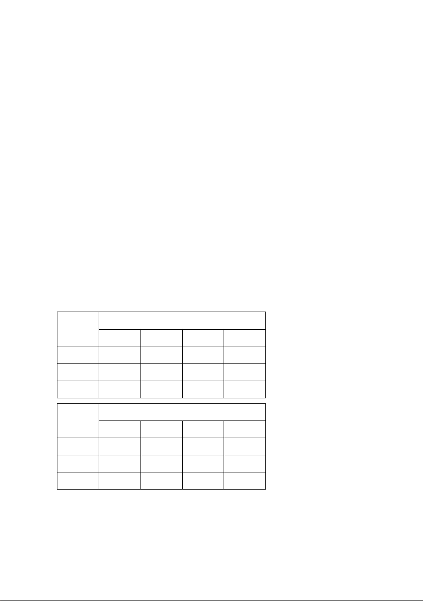
Grade of
service
Calls at 3 min. per hour The table contains some
sample values for the calculation of the traffic volume
depending on the grade of
service, call duration and
number of calls per hour.
Using the data you have
determined about the
telephony behaviour, you
can realistically estimate
your requirements.
10 50 100 500
0 % 0.5 E 2.5 E 5 E 25 E
2 % 0.49 E 2.45 E 4.9 E 24.5 E
4 % 0.48 E 2.4 E 4.8 E 24 E
Grade of
service
Calls at 15 min. per hour
10 50 100 500
0% 2.5 E 12.5 E 25 E 125 E
2% 2.45 E 12.25 E 24.5 E 122.5 E
4% 2.4 E 12 E 24 E 120 E
VoIPon www.voipon.co.uk sales@voipon.co.uk Tel: +44 (0)1245 808195 Fax: +44 (0)1245 808299
Page 17

15
P
rojecting the DECT network
Alternative calculation for small systems
F
or smaller systems, an approximate evaluation of the traffic volume can be sufficient.
Examples:
The traffic volume is evaluated for every area as "low", "medium" or "high". The evaluation
specifies the number of handsets that can conduct calls simultaneously as a percentage:
Hotspots
A hotspot is an area in which more calls than average are conducted simultaneously, e.g.,
open-plan offices or other areas where there are a lot of handsets in a small space.
You can cover such areas with several base stations since the DECT bandwidths in the coverage areas of neighbouring base stations add up. The DECT standard provides 120 radio
channels that can be shared by several base stations. In practice, however, approximately
only one quarter of these radio channels can be used without special measures, since the
neighbouring channels interfere with one another. This results in a practical value of a
maximum of 30 simultaneous connections. With a maximum of eight handsets per base
station, this means that four Gigaset N720 IP PRO base stations would be required.
If we assume that a maximum of 50% of the available handsets are making a call simultaneously in a hotspot, 60 handsets can be used with four base stations.
If interference frequently occurs at a hotspot or more than 30 connections are required
simultaneously, the following measures are possible:
u Distribute the base stations that cover the hotspot as widely as possible at the bound-
aries of the hotspot so that they are as far away from each other as possible and mutual
interference is minimised.
u If this measure is not sufficient, use walls or other suitable means to diminish the
strong signals.
u It might also be helpful, if the circumstances at the location allow, to arrange the base
stations in the shape of a ball, i.e., cover the hotspot through floors and ceilings.
When optimising the coverage of the hotspot areas, make sure that handsets do not suddenly occupy the call channels of the hotspot base stations that were previously supplied
by other base stations. When establishing a connection, handsets always occupy channels of the base station that provides the strongest signal. Therefore, moving the hotspot
base stations may affect other base stations and you may have to relocate the base stations of the entire network.
Evaluation % Maximum number of handsets that can be
operated from one base station
Low Approx. 10% 80
Medium Approx. 25% 32
High Approx. 50% 16
VoIPon www.voipon.co.uk sales@voipon.co.uk Tel: +44 (0)1245 808195 Fax: +44 (0)1245 808299
Page 18

16
P
rojecting the DECT network
Material characteristics and in
terference factors
There are a number of interference factors that influence the range and quality of the
transmission in particular. The types of interference factors include:
u Interference as a result of obstacles that diminish the signal transmission, creating
radio shadows
u Interference through reflection that restricts the call quality (e.g., crackling or back-
ground noise)
u Interference through other radio signals that can lead to errors in transmission
Interference through obstacles
Possible obstacles are:
u Building constructions and installations such as reinforced concrete ceilings and walls,
stairwells, long corridors with fire doors, uptakes and cable channels.
u Metal-clad rooms and objects such as cold stores, computer rooms, metallised glass
areas (reflections), firewalls, tank systems, refrigerators, electrical boilers etc.
u Movable metal objects such as lifts, cranes, carts, escalators, shutters
u Room furnishings such as metal shelves, filing cabinets
u Electronic devices.
It is often difficult to locate the exact source of the interference; particularly if the reception power of the local DECT signals fluctuates strongly within a few centimetres. In these
cases, the interference can be reduced or corrected by small changes to the position.
Loss of range through building materials in comparison to a free wireless
field:
Please note
Wireless coverage in lifts is normally poor or not available at all (£ page 41).
Glass
, wood, untreated Approx. 10%
Wood, treated Approx. 25%
Plasterboard Approx. 27 – 41%
Brick wall, 10 to 12 cm Approx. 44%
Brick wall, 24 cm Approx. 60%
Aerated concrete wall Approx. 78%
Wired glass wall Approx. 84%
Reinforced concrete ceiling Approx. 75 – 87%
Metal-coated glass Approx. 100%
VoIPon www.voipon.co.uk sales@voipon.co.uk Tel: +44 (0)1245 808195 Fax: +44 (0)1245 808299
Page 19

17
P
rojecting the DECT network
Interference from other cells and networks
DEC
T is very robust against interference from other wireless networks. For example, coexistence with WLAN is not a problem. Most other asynchronous DECT single base stations do not present a problem either.
Problems may occur in special cases, such as an environment where there is a very high
level of DECT usage. This applies when there are co-existing asynchronous DECT base stations but, even more so, when base stations have been installed too close together to
cover a hotspot, for example.
Despite sufficient signal strength, the following interference can occur:
u Unexpected termination of the connection
u Loss of synchronisation of handsets
u Poor voice quality
¤ When interference occurs because base stations are installed too closely together, try
to resolve the problem with the measures described in the
Hotspots section (increase
the distances, use obstacles to absorb the interference,
£ page 15)
¤ If you have found other DECT sources, check whether you can switch them off, relocate
them or integrate them in your DECT network.
Summary
Wireless traffic interference can have many causes that cannot all be determined in
advance, that increase or decrease due to mutual influences and that can change during
operation.
Therefore, the actual influence of interference factors on reception and voice quality can
only be determined by taking measurements. However, the measurements also only provide an image of the wireless network at the time of measurement. We therefore recommend that when you plan the DECT network areas where interference can be expected,
you err on the side of caution when you interpret the limit values.
VoIPon www.voipon.co.uk sales@voipon.co.uk Tel: +44 (0)1245 808195 Fax: +44 (0)1245 808299
Page 20

18
P
rojecting the DECT network
Preliminary identification of the positions of the base sta
tions
Now plan the positions of the base stations. Take the following into consideration:
u The information you have collected regarding the requirements for the telephone net-
work
u Your synchronisation planning
u The technical conditions for the wireless DECT.
First create a plan in which you then enter the locations of the base stations. You can use
existing building and supply plans, if applicable. For very large buildings, you may be able
to work with partial floor plans and then merge the results of the measurements into the
evaluation.
Creating a planning drawing
Create a planning drawing from the information you have collected in the preliminary
examination of the location. Enter building dimensions, hotspot areas and any sources of
interference already identified.
Examples:
u The numbers in the rooms reflect the required number of DECT telephones.
u Areas with high-density traffic are marked as hotspots (HS).
u The walls marked in bold are assumed to have a high absorption effect, or reflections
can be expected.
u The dotted lines on the two outer walls indicate tinted windows (coated with metal
film).
u The stairwell should be covered by DECT wireless transmission. There is a lift here.
30 m
50 m
HS
HS
WC/
store
Stairs
Computers
VoIPon www.voipon.co.uk sales@voipon.co.uk Tel: +44 (0)1245 808195 Fax: +44 (0)1245 808299
Page 21

19
P
rojecting the DECT network
Positioning the base stations in the plan
No
w enter the base stations.
u The example shows five base stations.
u One base station is used to show how, by drawing in transmission directions for the
wireless signal, you can estimate how many base stations can see each other and
which building areas the wireless signal could reach.
u For the hotspot in the room at the top left, two additional base stations have been
planned in parallel.
u If full wireless coverage is required for the stairwell, measurements must be performed
to check whether a further base station has to be located here.
u You must also check whether the base stations planned are sufficient for the second
hotspot.
You then check these initial assumptions later using the measurements (page 20).
WC/
store
Computers
Stairs
HS
HS
VoIPon www.voipon.co.uk sales@voipon.co.uk Tel: +44 (0)1245 808195 Fax: +44 (0)1245 808299
Page 22

20
T
aking measurements
Taking measurements
You have:
u Determined the requirements for the telephone network (£ page 9)
u Planned the number of base stations and their positions (£ page 18)
u Set up and operated the measurement equipment.
If you are using the Gigaset N720 SPK PRO (Site Planning Kit), you can find information
about setting it up on
£
page 29.
You can now start the measurements for your planned DECT network. The aim of the
measurements is to determine the following:
u Is sufficient wireless coverage and a good voice quality guaranteed everywhere in the
desired area?
u Is synchronisation of the bases stations ensured in their planned positions?
u Is a handover between the base stations possible where it is required?
The requirements from these three aspects must be taken into account in the measurements. For information on this, please also refer to the Conditions for the positioning of
the base sta
tions section
£
page 10.
Notes for taking the measurements
u Take two different measurements:
– Measure the connection quality in the wireless coverage area for the planned base
stations.
– Measure the signal strength between the base stations (synchronisation measure-
ment).
u To measure the connection quality, establish a telephone connection. It is helpful if the
measurements are performed by two people, since they can check the voice quality
and interference on both measuring handsets directly in a call. If only one person performs the measurements, the connection quality can be checked using the test tone
of the base station (
£
page 38).
u You can also test the connection quality by holding the handset to your ear as you
measure, in the same way as you would in a real telephony situation. Turn around as
you do so. Note how the acoustics quality of the test tone changes. If interference
occurs at the limit of the range (e.g., crackling), power at the measuring site is critical.
Your head can impair reception. For this reason, the test against your ear is an additional check for verifying the reception quality in limit areas.
u Use the measuring handset in idle status to measure the signal strength between the
base stations, as it is the measured signal strength and not the voice quality that is relevant in this situation.
u Using the stand, position the measuring base station as precisely as possible in relation
to the intended position for the base station.
u To measure the signal strength between base stations, position the measuring hand-
set in the exact planned position of the base station. For example, if you want to position the base stations at a height of 3 m, make sure the measuring handset is at this
height.
u Move metal objects as far away as possible from the measuring base station as they
can influence the measurement.
VoIPon www.voipon.co.uk sales@voipon.co.uk Tel: +44 (0)1245 808195 Fax: +44 (0)1245 808299
Page 23

21
T
aking measurements
u Do
cument the progress of the measurement by entering it in the layout plan (horizon-
tally and, where applicable, vertically) and in a measurement log.
u In order to be able to recognise subsequent changes, it is helpful to document the
planned assembly positions of the individual measurement series and their environment with photographs.
u If the PABX is to be used for several floors or very high rooms (e.g., with a gallery), you
must also measure the vertical range and enter it in a plan of the building. For further
information on this, please also refer to the
DECT installations in special environ-
ments
chapter
£ page 41.
Fluctuations in the measurement result
When you are performing the measurements, the signal strength displayed on the handset can fluctuate strongly, particularly if you are moving around with the handset. The
base stations have two aerials, so the handset displays the values for the aerial for which
it receives the best signal. Since the measuring handset takes measurements at defined
time intervals (2.5 seconds as standard), the values can change quickly.
For example, if you block the signal for the aerial that is in a better position for the handset
with part of your body, the handset receives the signal from the weaker aerial. Turning
your body slightly can significantly alter the measurement value, since the handset is suddenly able to receive the signal from the "better" aerial. By moving around, you determine
an average value that you can use as the measurement value.
If the fluctuations are strong, it makes sense to perform the measurement while a connection is established as you then have an additional check based on the voice quality.
When the PABX is being operated in real-life situations, these fluctuations are barely
noticeable as the base stations automatically establish the connection with the best positioned aerial.
Defining limit values
During the measurement process, the measuring handsets receive wireless signals from
the measuring base station and display various characteristics for the reception quality.
The following are relevant for the reception quality:
u Reception power
u Connection quality
The values specified below are guidelines for determining limit values for operating the
DECT telephone system under optimum conditions. Since the DECT network can be
restricted by many factors that can also occur temporarily, we do not recommend positioning the base stations at the limit values. Instead, you should include a buffer according to the requirements for grade of service and voice quality. It may be acceptable for
example, that voice quality is restricted at times in the basement, and that calls cannot
always be made there. In contrast, restrictions are unacceptable for meeting rooms where
telephone conferences are held.
VoIPon www.voipon.co.uk sales@voipon.co.uk Tel: +44 (0)1245 808195 Fax: +44 (0)1245 808299
Page 24

22
T
aking measurements
Reception power
T
he reception field strength is measured to assess the quality of transmission. The reception
power (proportional to the field strength) is displayed on the measuring handset in
dBm
(
£
page 48). A very good reception power is approximately –50 dBm. Systems that are
measured at up to –60 dBm generally offer a good quality. For measurements up to –70 dBm,
the measurement must be checked and evaluated with an audio connection to ensure sufficient quality. A handover is no longer possible in this area.
Different limit values can be used for the measurement, based on the quality or use of
specific areas (e.g., office, corridor, basement). Different quality requirements can also be
defined at the various base stations within a partial system.
Typical limit values for normal, low-interference environments are:
§§1§§ Limit value for secured voice quality: –65 dBm
This is the value at which a handset must receive the signal of a base station for a subscriber to be able to benefit from good quality telephony. For an interference-free
handover, the handset must receive both base stations at this level of quality.
§§2§§ Limit value for synchronisation: –70 dBm
This is the value at which a base station must receive the signal of another base station
to be able to synchronise.
The following table gives an initial guideline for the quality of the wireless connection.
Reception power Evaluation of the quality
–50 dBm Very good
–60 dBm Good
–65 dBm Satisfactory
–70 dBm Adequate
–73 dBm Weak, not suitable
–76 dBm Poor, not suitable
VoIPon www.voipon.co.uk sales@voipon.co.uk Tel: +44 (0)1245 808195 Fax: +44 (0)1245 808299
Page 25

23
T
aking measurements
Connection quality
I
n principle, the measurement of the field strength should always be supplemented by a
check of the connection quality. Interference, e.g., through reflection or external systems
that influence the voice quality, can also occur with good reception power.
Therefore, in addition to the reception power, the
Frame quality is also displayed on the
measuring handset. This indicates the percentage rate of the packages received without
errors in a measurement interval. The optimum value is 100%.
As a rule of thumb, 2% reduction in the frame quality leads to a devaluation by one level
in the quality table illustrated above. Example: the measurement values –60 dBm with a
frame quality of 94% lead to the evaluation "Poor, not suitable", since a quality loss of 6%
leads to a devaluation by three levels.
Reception power Frame quality Evaluation of the quality
–60 dBm 100 % Good
–60 dBm 98 % Satisfactory
–60 dBm 96 % Adequate
–60 dBm 94 % Weak, not suitable
–60 dBm 92 % Poor, not suitable
VoIPon www.voipon.co.uk sales@voipon.co.uk Tel: +44 (0)1245 808195 Fax: +44 (0)1245 808299
Page 26

24
T
aking measurements
Measuring the wireless range of th
e planned base stations
Take two different measurements.
§§1§§ Measure the connection quality between the measuring handset and measuring base
station in their wireless cells to ensure that sufficient voice quality is guaranteed at every position in the required coverage area. Taking the same measurement for the neighbouring station produces the overlap zone required for a handover.
§§2§§ Measure the strength of the signal from the measuring base station that you receive at
the planned position of the neighbouring base station to ensure sufficient synchronisation overlap.
Measurement sequence
The sequence in which you measure the wireless range of the planned base stations
depends on the size of your DECT network and your assumptions with regard to the existing "problem areas". As a rule of thumb, first measure the base stations whose positions
have the least leeway.
Take the following aspects into consideration:
u Assumed problem areas
For base stations that are to cover specific problem areas, e.g., a stairwell or entrance
area, there are often few alternative positioning options. In this case, measure these
base stations first because the positioning of all other base stations depends on these
initial positions.
u For large installations
The more base stations you use, the higher the requirements of the synchronisation
hierarchy (
£ page 12). In this case, we recommend starting with the base station for
whi
ch a subsequent change would mean the greatest effort. This is usually the base
station with sync level 1. Start here and move outwards from sync level to sync level.
u For small installations
Here it makes sense to start with the base station where the highest call traffic is to be
expected, e.g., base stations in hotspots or other high-traffic areas. Once the coverage
of these areas is ensured by measurement, check the positioning of the other base stations.
VoIPon www.voipon.co.uk sales@voipon.co.uk Tel: +44 (0)1245 808195 Fax: +44 (0)1245 808299
Page 27

25
T
aking measurements
Measuring the cell of a base station
¤ T
emporarily secure the measuring base station in the position in which the base sta-
tion is to be installed.
¤ Establish a telephone connection between the two measuring handsets or activate
the continuous test tone of the measuring base station (
£ page 38).
¤ M
ove away from the base station with the handset, observing the display and the signal in the earpiece, until the limit value of –65 dBm is displayed or a wireless transmission boundary is reached (e.g., lift, exterior wall). Transfer this point to your plan and
enter the value in the measurement log.
¤ Use this method to determine the border line around the base station. The theoretical
ideal case of a ring-shaped transmission is considerably altered in reality by walls
(depending on the construction material) and metal furnishings.
¤ Check the voice quality in the limit areas using the connection to the second measur-
ing handset or the measuring tone of the base station.
¤ Enter deviations in the reception signal measurement of the voice quality in the layout
plan or the measurement log.
Example of a measurement log for the cell of a base station
Measuring point Base station A
1 –60 dBm/100%
2 –65 dBm/98%
. . . . . .
. . . . . .
9 –73 dBm/70%
WC/
store
Stairs
Computers
1
2
9
A
B
C
D
E
VoIPon www.voipon.co.uk sales@voipon.co.uk Tel: +44 (0)1245 808195 Fax: +44 (0)1245 808299
Page 28

26
T
aking measurements
If you have measured the cells of several base stations, the results may look like this, for
example:
M
easuring points where two base stations are received with at least –65 dBm are located
in an overlap zone of the two base stations in which a handover is possible (highlighted
grey in the table).
Measuring the synchronisation overlap of neighbouring base stations
For the base stations to be able to synchronise, the signal strength between two neighbouring base stations must not be less than –70 dBm. This value applies in good environmental conditions,
£
page 21.
Proceed as follows for the measurements:
¤ Leave the measuring base station at the last measuring site and proceed with the
handset to the planned position of a base station that is to synchronise with the first
base station.
In order to reliably assess the synchronisation, you must be located, with the handset,
at the exact position of the planned base station (use a ladder to measure at the correct height, if necessary).
¤ Check whether the signal is within the limit of -70 dBm at 100% frame quality. If this is
not the case, you should change the location of the base station until this minimum
requirement is met.
Measuring
point
Base station A Base station B Base station C Base station D
1 –60 dBm/100%
2 –50 dBm/98%
3 –65 dBm/100%
4 –48 dBm/100%
5 –55 dBm/98%
6
–65 dBm/100% –50 dBm/100%
7 –68 dBm/96% –59 dBm/100%
8
–55 dBm/98% –46 dBm/98%
9 –60 dBm/96%
10
–52 dBm/98% –65 dBm/100%
11
–63 dBm/100% –57 dBm/100%
12
–48 dBm/98% –42 dBm/100%
13 –46 dBm/98%
14 –40 dBm/100%
15
–60 dBm/98% –52 dBm/100%
16
–43 dBm/100% –42 dBm/100%
17 –56 dBm/100%
18 –50 dBm/98%
19 –53 dBm/100%
20 –60 dBm/98%
VoIPon www.voipon.co.uk sales@voipon.co.uk Tel: +44 (0)1245 808195 Fax: +44 (0)1245 808299
Page 29

27
T
aking measurements
¤ I
nstall the measuring base station at this location and take the measurements as for
the first position.
¤ Enter the results in the plan and the measurement log.
¤ Now take this measurement for all planned assembly locations.
Example of a measurement log for measuring the synchronisation overlap
The result of the measurement is that the signal strength is sufficient for synchronisation
everywhere. Base station E only receives base station D with sufficient quality.
Here, a sensible synchronisation hierarchy would be:
Measuring
point
Base station A Base station B Base station C Base station D Base station E
A –52 dBm/100% –40 dBm/100% –58 dBm/100% ---B –50 dBm/100% –48 dBm/100% ---- –70 dBm/92%
C –42 dBm/100% –46 dBm/100% –50 dBm/100% ---D –60 dBm/100% ----- –48 dBm/100% –64 dBm/100%
E ---- –68 dBm/94% ---- –62 dBm/100%
Sync level 1 Base station C
Sync level 2 Base stations A, B and D
Sync level 3 Base station E
A
B
C
D
E
VoIPon www.voipon.co.uk sales@voipon.co.uk Tel: +44 (0)1245 808195 Fax: +44 (0)1245 808299
Page 30

28
T
aking measurements
Evaluating measurements
The
graphical display of your measurement results in the layout plan shows the overlap
areas of the individually planned base stations.
In the example, limitation lines are drawn for the wireless coverage for base stations A and
D. The overlap areas are very good for both stations; synchronisation is also guaranteed
between A and D. However, the measurement results of the other stations must be used
to check whether a further base station is required in the shaded areas.
¤ Using the measurement results (where necessary), define new positions for the base
stations and check them with further measurements.
Note that moving one installation location also influences the other measurement
results. Always consider how this affects the synchronisation of the base stations.
¤ Enter the determined optimum installation locations for the base stations in the plan
(including the height and special construction circumstances, if necessary). We recommend you also document the assembly positions with photographs.
¤ In particular, check rooms or areas with very high wireless signal shielding (e.g., lifts,
reinforced concrete ceilings, etc.) and add further base stations to your plan where
necessary.
Once the measurements are complete and the positions of the base stations have been
defined, the telephone system can be installed. This is described in the user guide for the
Gigaset N720 IP PRO and Gigaset N720 DM PRO.
Recommendation
After installation and commissioning of the DECT network, the voice quality, roaming
and handover should be checked again with the system telephones.
A
D
VoIPon www.voipon.co.uk sales@voipon.co.uk Tel: +44 (0)1245 808195 Fax: +44 (0)1245 808299
Page 31

29
W
orking with the Gigaset N720 SPK PRO
Working with the Gigaset N720 SPK PRO
The Gigaset N720 SPK PRO (Site Planning Kit) helps you to plan and install your DECT
multi-cell system. It contains one measuring base station, two measuring handsets and
further helpful accessories for exact determination of the DECT environmental conditions
for the planned network and is delivered in a case.
You can use the measuring devices in the case to determine the
DECT wireless coverage at your location, establish how many base
stations are required and their optimum location and find sources
of interferences in the wireless network.
Checking the package contents
§§1§§ Measuring base station mounted on a carrier
§§2§§ Battery pack with eight rechargeable batteries (AA)
§§3§§ Battery charger with three different plug-in modules (Europe, Great Britain and the USA)
§§4§§ Power adapter for measuring base station (only r
equired if the device is not powered
via batteries)
§§5§§ Key for locking the case
1
4
3
2
5
VoIPon www.voipon.co.uk sales@voipon.co.uk Tel: +44 (0)1245 808195 Fax: +44 (0)1245 808299
Page 32

30
W
orking with the Gigaset N720 SPK PRO
Further recommended accessories
§§6§§ Two Gigaset S810H measuring handsets (specially calibrated for measurement opera-
tions)
§§7§§ Eight rechargeable batteries (AAA) for the measur
ing handsets (two reserve batteries
each)
§§8§§ Two chargers with power adapter for the measuring handsets
§§9§§ Two Gigaset ZX400 headsets
§§10§§ CD-ROM with user documentation
§§11§§ Planning and recording materials with pen
6 7 8
9 10 11
Stand
To obtain an exact measurement, we recommend that you
mount the measuring base station and battery carrier securely
on a stand. The base carrier is fitted with a thread connection
for this purpose. This enables you to simulate the installation
of a base station at every possible height and check the layout
and range of the network.
The stand should have a screw thread and be extendable to a
height of 2.50 to 3.00 m.
VoIPon www.voipon.co.uk sales@voipon.co.uk Tel: +44 (0)1245 808195 Fax: +44 (0)1245 808299
Page 33

31
W
orking with the Gigaset N720 SPK PRO
Before you begin
Plea
se note that the measuring devices run on batteries that must be charged before you
start taking measurements. Bear this in mind when planning your time.
You need eight batteries for the measuring base station, provided as a battery pack. The
case contains a charging device for charging the battery pack.
The charging time is
approx. three hours.
You need two batteries for each measuring handset. These can be charged both in the
chargers and in standard charging devices. The charging time in the charger is approx.
8.5 hours.
Setting up the measuring base station
To ensure freedom of movement when measuring and not be dependent on being able
to reach a power connection, operate the measuring base station with external batteries.
The case contains a battery pack with eight integrated batteries and one charging device
for this purpose.
Preparing the base carrier
Please note
Use only the rechargeable batteries (£
page 45) recommended by Gigaset Commu-
nications GmbH, i.e., never use conventional (non-rechargeable) batteries, otherwise
serious health risks and personal injury cannot be ruled out. For example, the outer
casing of the batteries could be damaged or the batteries could explode. The phone
could also malfunction or be damaged as a result of using batteries that are not of the
recommended type.
¤ Remove the base carrier from the case
together with the measuring base station
and battery pack.
¤ Slide the lid to the left to open the battery
compartment
§§1§§.
Lift the lid gently with your fingernail to
get past the lock on the right edge.
¤ Plug the connector on the battery pack
cable onto the two pins on the left side of
the battery compartment
§§2§§.
W
arning: the connector is shaped so that it
can only be attached the correct way round.
If the connector is forced into the wrong
position, the pins may be damaged rendering the device unusable.
1
2
VoIPon www.voipon.co.uk sales@voipon.co.uk Tel: +44 (0)1245 808195 Fax: +44 (0)1245 808299
Page 34

32
W
orking with the Gigaset N720 SPK PRO
Charging the batteries
¤ I
nsert the battery pack into the battery
compartment in the base carrier
§§3§§.
¤ Slide the lid onto the battery compart-
ment
§§4§§ until it clicks into place.
The measuring base station is connected to the power supply by means of
a cable
§§1§§.
The charging socket is located behind
opening
§§2§§, while there is a switch for
switching between "Operation" and
"Charge" behind opening
§§3§§.
¤ Move the switch to the charging
position by sliding it towards the
charging socket.
¤ Plug the battery charger into a mains
socket
§§4§§.
You may need to attach the appropriate plug-in module first.
¤ Plug the battery charger plug into
the charging socket on the back of
the base carrier
§§5§§.
¤ Char
ge the batteries until the
charger's charging indicator lights up.
¤ When the batteries are charged,
unplug the charger plug from the
charging socket and return the
switch to the "Operation" position.
3
4
2
1
3
4
5
VoIPon www.voipon.co.uk sales@voipon.co.uk Tel: +44 (0)1245 808195 Fax: +44 (0)1245 808299
Page 35

33
W
orking with the Gigaset N720 SPK PRO
Alternative power supply
The
measuring base station is supplied with power via the battery pack inserted in the
battery carrier. Alternatively, you can also use one of the following power supplies:
Please note
u The measuring station has sufficient power when the LED
on the front is illuminated.
u To save energy, position the switch on "Charge" when you
do not need the device.
¤ Unplug the power cable plug
from the base station.
Connecting to the mains power
supply
¤ Connect the cable for the power
adapter to the power
connection on the measuring
base station
§§1§§.
¤ Plug the power adapter into a
mains socket
§§2§§.
2
1
VoIPon www.voipon.co.uk sales@voipon.co.uk Tel: +44 (0)1245 808195 Fax: +44 (0)1245 808299
Page 36

34
W
orking with the Gigaset N720 SPK PRO
Mounting the measuring base sta
tion on the stand
Connecting to a switch with PoE
functionality (Power over
Ethernet).
¤ Connect the LAN socket on the
measuring base station
§§1§§ to a
connection on an Ethernet
switch
§§2§§.
Use a shielded Ethernet cable.
The base carrier is fitted with a bracket for
mounting the measuring base station on a
stand.
¤ Position the thread of the battery carrier
on the stand and screw the battery carrier into place.
1
2
VoIPon www.voipon.co.uk sales@voipon.co.uk Tel: +44 (0)1245 808195 Fax: +44 (0)1245 808299
Page 37

35
W
orking with the Gigaset N720 SPK PRO
Starting up the measuring handset
C
onnecting the charging cradle
Inserting the batteries and closing the battery cover
¤ Remove the measuring handsets and
accessories from the case. For each handset there is:
§§1§§ One charger
§§2§§ One power adapter
§§3§§ One battery cover
§§4§§ One belt clip
§§5§§ One plastic cover for the headset
socket
§§6§§ Four batteries (AAA), of which two are
reserves
The display and keypad are protected by
plastic films; please remove them!
¤ Connect the flat plug of the power
adapter to the charger
§§1§§.
¤ Insert the power adapter into a mains
socket
§§2§§.
If you have to remove the plug from the
charger again:
¤ Press the release button §§3§§ and discon-
nect the plug.
¤ Insert the batteries with the polarity in
the correct direction. The polarity is indicated in/on the battery compartment.
¤ First insert the battery cover at the top.
¤ Then press the cover until it clicks into
place.
To open the battery cover; for example, to
change the batteries:
¤ Insert your fingernail into the notch on
the casing (see arrow), then pull the battery cover in an upward direction.
§§1§§
§§2§§
§§3§§
§§4§§
§§5§§
§§6§§
§§1§§
§§2§§
§§3§§
VoIPon www.voipon.co.uk sales@voipon.co.uk Tel: +44 (0)1245 808195 Fax: +44 (0)1245 808299
Page 38

36
W
orking with the Gigaset N720 SPK PRO
Initial charging and discharging of the ba
tteries
Battery charging status in the display
The charging status of the battery is shown in the top right
corner of the display:
Connecting a headset to the handset
To assess the quality of the sound transmitted from the measuring station, you can connect headsets to the measuring handsets.
The correct charge status can only be displayed if the batteries are fully charged and
discharged first.
¤ Charge the handset in the charger for
8.5 hours.
¤ After charging, remove the handset from
the charger and only replace it when the
batteries are fully discharged.
The handset must only be placed in the designated charger.
{
Lights up white Charged over 66%
{
Lights up white Charged between 34% and 66%
y
Lights up white Charged between 11% and 33%
y
Lights up red Charged below 11%
y
Flashes red Battery almost empty (less than ten minutes of operating time)
x
Lights up white Battery charging
The connection for one of the headsets
delivered is on the left side of the measuring
handset.
This also means that your hands are free to
enter the locations determined in the plan
and you can read the display during the
measurement phase.
The headset volume corresponds to the settings for the earpiece volume.
V
VoIPon www.voipon.co.uk sales@voipon.co.uk Tel: +44 (0)1245 808195 Fax: +44 (0)1245 808299
Page 39

37
W
orking with the Gigaset N720 SPK PRO
Operating the measuring handset
The mea
suring handsets
u Switch on automatically when they are placed in the charger
u Are already registered to the measuring base station on delivery
u Are already in metering mode on delivery.
Display in metering mode
In metering mode, the display shows the current status values of the connection to the
base station. The values are updated at brief intervals. You can change this measuring
interval (
£ page 40).
Display in idle status
The display shows the following information in idle status:
The following information is also displayed:
You will find detailed information on evaluating the measurement results in the
Defining
limit values section
£ page 21.
Pl
ease note
This section only describes the functions of the handset relevant for measurements.
For information on the standard functions of the Gigaset S810H handset, see the user
guide for the device. See the product page at www.gigaset.com
.
Values for determining the connection quality:
RSSI value
RSSI value. Base station signal reception
strength with the best reception in dBm.
Acceptable value: –20 to –70 dBm.
Units for signal strength
£
page 40.
Fr. quality Frame quality. Percentage rate of the pack-
ages received without error in the last measuring interval.
Acceptable value: 95–100%
Frequency Frequency. Carrier frequency of the signal received. Value range: 0–9
Slot pair Duplex
Slot pair used (0–11)
Time slot for the reception channel on which the measurement was performed.
Note: during transition to the connection status, the value 15 is occasionally displayed.
RPN RPN (Radio Fixed Part Number)
Identifier for the base station to which the handset is connected. The value
is displayed in hexadecimal format.
V
i
RSSI
value: -30dBm
Frequency: 1
Slot pair: 04
RPN: 50 hex
Fr. quality: 100 %
Calls
VoIPon www.voipon.co.uk sales@voipon.co.uk Tel: +44 (0)1245 808195 Fax: +44 (0)1245 808299
Page 40

38
W
orking with the Gigaset N720 SPK PRO
Display not in idle status
Check
ing the quality of the connection to the measuring base
station
Connecting the measuring handsets
If two people perform the measurements, you can check the voice quality by establishing
a connection between the two measuring handsets.
The handsets are in metering mode in idle status.
u Initiate internal call.
~ Enter the internal number of the other handset using the keypad.
Or:
u Initiate internal call.
s Select handset. Your own handset is identified by a "<" on the right.
c Press the talk key.
Calling all handsets
u Press and hold.
Switching on the continuous test tone for the base station
If you perform the measurements alone, you can play a continuous test tone to test the
connection to a measuring base station from a measuring handset.
~ Enter the number string ***O22 via the keypad.
c Press the talk key.
The test melody is played via the loudspeaker. If you have connected a headset, press the
speaker key
d to hear the melody.
Activating/deactivating the measuring handset
The measuring handset is activated automatically when it is placed in the charger. This
means that it is activated after charging in the charger.
a With the phone in idle status, press and hold the end call key (confirmation
tone) to deactivate the handset. Press and hold the end call key again to reactivate the handset.
If the display is not in idle status, it shows the measurement data at the top edge.
-30dBm-1-04-50H-100
VoIPon www.voipon.co.uk sales@voipon.co.uk Tel: +44 (0)1245 808195 Fax: +44 (0)1245 808299
Page 41

39
W
orking with the Gigaset N720 SPK PRO
Activating/deactivating speaker mode
Y
ou can also test the quality of the connection via the loudspeaker instead of via the
headset.
d Press the speaker key to switch between earpiece mode and speaker mode.
¤ In this case, place the plastic cover supplied on the headset socket. This improves the
quality in speaker mode.
Activating/deactivating metering mode
The handset is in metering mode when it is activated.
Exiting metering mode
You exit metering mode by resetting the handset:
v £ Ï £ System £ Handset Reset
Reactivating metering mode via the service menu
If you have exited metering mode, you can reactivate it via the service menu. Proceed as
follows:
a
Press and hold the off key to deactivate the handset.
4 a Press and 4 at the same time and hold them down. Then press
and hold the on key
a.
The handset is now in service mode.
~
Enter the five-digit service PIN. On delivery this is 76200.
The service menu is opened.
s Select the Metering Mode entry with the
navigation key.
§Change§ Press the display key to activate the entry.
As soon as you have activated metering mode, the RSSI
measurement menu is opened.
Here you can change the settings for the unit of measure
and the measurement interval.
Metering Mode
Working Time
Apprv. Narr.Band
Apprv. Wide Band
Back Change
Service
³
´
´
SAR
VoIPon www.voipon.co.uk sales@voipon.co.uk Tel: +44 (0)1245 808195 Fax: +44 (0)1245 808299
Page 42

40
W
orking with the Gigaset N720 SPK PRO
Changing the settings f
or metering mode
In the service menu, you can change the unit of measure and the measurement interval
for metering mode.
§Start§ Press the display key to activate metering mode.
§Back§ Press the display key to exit the service menu again.
The handset is deactivated. When you reactivate it, it is in metering mode with the
selected settings.
Metering Mode (unit of measure)
In the display, the signal strength (RSSI value) is displayed
in dBm as standard. You can also display the signal
strength as a percentage value. This represents the signal
strength of the package received as a ratio of the maximum possible RSSI (100%).
r Use the navigation key to select the desired display
of the signal strength.
dBm: The signal strength measured is displayed in
dBm. This is preset and is the recommended mode.
%: The signal strength measured is displayed as a
percentage of the maximum RSSI
SEN: Not relevant
Metering range (measurement interval)
The measurement interval defines the time intervals at
which measurements are taken.
Value range: 06–16 (1.0 s–2.5 s)
Recommended value: 16
r Use the navigation key to select the required meas-
urement interval.
Metering Mode:
<dBm
Metering range:
06
Back Change
RSSI measurement
>
Metering Mode:
dBm
Metering range:
< 06
Back Start
RSSI measurement
>
Please note
You should not make changes to other settings in the service menu.
VoIPon www.voipon.co.uk sales@voipon.co.uk Tel: +44 (0)1245 808195 Fax: +44 (0)1245 808299
Page 43

41
D
ECT installations in special environments
DECT installations in special environments
The
Projecting the DECT network and Taking measurements chapters describe all pre-
requisites and steps for planning a DECT network. In addition to the examples and applications described there, this chapter contains notes for special construction or topographical requirements.
DECT networks over several floors
If the DECT network is to cover several floors of a building, you must consider the following points when planning the number and location of base stations:
u What material are the suspended ceilings made from?
If they are reinforced concrete, only one ceiling can be positioned between the base
station and telephone for a direct wireless path. Furnishings and partitions in rooms
etc. can restrict the wireless transmission even further.
Use measurements to check where further base stations are required.
u To what extent must a handover between the floors be guaranteed?
In this case, the base stations must be positioned such that stairwells are also completely covered. Note also that any fire doors or walls can reduce the wireless transmission severely.
Add the vertical levels of your planned coverage areas to your measurement plan and
record the vertical transmission of the DECT network.
u No handover between floors required
In this case you can work with clusters (more cost-effective). If you set up one cluster
for each floor, the base stations of the cluster are synchronised with one another and
a handover is possible. A handover is not possible between the floors, but the IP PABX
functions (VoIP configuration, directories, etc.) are available in all clusters.
Stairwells and lifts
Stairwells often have particularly absorbent walls (e.g., reinforced concrete); access to the
stairwell may be restricted by fire doors. Planning of the DECT network is therefore subject to special requirements here.
If you want calls via the DECT network to be possible in the stairwell, the most cost-effective variant is to install one (or even several) base station as a separate cluster.
If a handover is required in the stairwell, you should check the position of the stairwell to
the corridors (transitions, doors, fire doors), measure the wireless coverage and, if necessary, provide one or more base stations for wireless coverage of the stairwell.
Making calls in lifts is usually not possible due to the highly absorbent and/or reflective
materials. However, if this is a requirement, you can check whether you can achieve sufficient signal strength and quality for making calls in a lift by installing a separate base station in the lift shaft.
VoIPon www.voipon.co.uk sales@voipon.co.uk Tel: +44 (0)1245 808195 Fax: +44 (0)1245 808299
Page 44

42
D
ECT installations in special environments
Several buildings
Pla
nning a DECT installation for several buildings or for separate parts of buildings
requires clarification of the following points:
u Should calls only be possible within the internal rooms or across the whole site, even
in the outside area?
u In which area should handover be guaranteed?
The cheapest way to connect separate parts of buildings with the PABX is to use separate
clusters (subnet). In this case, only the wiring of the different buildings or building parts
via the LAN must be ensured. All telephones registered to the PABX can be used everywhere; however, handover is not always possible.
Outside area
The outside area of a building can often be included in the DECT network through a base
station close to a window. The prerequisite for this is that the glass in the window must
not contain any metal (metal film, wire mesh).
If the outside area cannot be covered by base stations within the building, a base station
can also be installed in the outside area. The base station should then be mounted in a
suitable external housing to protect it against weather conditions (available from thirdparty manufacturers). The limit values for the operating temperature of the base stations
(+5° to + 40°) must be taken into consideration.
The installation can be on a mast (not metal), on the roof or on a wall of the building.
Please note that the LAN connection must be guaranteed, as this supplies the device with
power and is also required for the connection to the DECT Manager.
The range on the site is up to 300 m, but may be restricted by other buildings, walls or
trees. A base station mounted in the outside area can also cover further indoor parts of
buildings if the walls of these areas do not reduce the radio signal too strongly.
For measurements outside, please note that weather conditions, e.g., rain or snow, can
significantly influence the send and receive properties. If necessary, perform further
measurements in different weather conditions; plan the radio coverage generously if you
want to guarantee secured reception. Changes in the vegetation (leaves on the trees,
growth of bushes) can also affect the radio conditions.
Handover over the whole site
If handover is to be achieved over the whole site, including all buildings, the transition
areas between internal rooms and the outside area must be planned and measured carefully.
Example: the building can only be accessed through a metal door with 100% absorption.
In this case, when the door is open the handover between the nearest base station
indoors and the base station for the outside area must be guaranteed. Both base stations
must be synchronised and (with the door open) have the required overlap area.
VoIPon www.voipon.co.uk sales@voipon.co.uk Tel: +44 (0)1245 808195 Fax: +44 (0)1245 808299
Page 45

43
En
vironment
Customer care and help
Questions? For rapid assistance, refer to this user guide or visit www.gigaset.com/pro
. The
trade outlet where you bought your PABX will be happy to help with further questions
relating to your Gigaset Professional PABX.
Questions and answers
If you have any queries about the use of your telephone, visit our website at
www.gigaset.com/pro
.
Environment
Our environmental mission statement
We, Gigaset Communications GmbH, bear social responsibility and are actively committed to a better world. Our ideas, technologies and actions serve people, society and the
environment. The aim of our global activity is to secure sustainable life resources for
humanity. We are committed to a responsibility for our products that comprises their
entire life cycle. The environmental impact of products, including their manufacture, procurement, distribution, utilisation, service and disposal, are already evaluated during
product and process design.
Further information on environmentally friendly products and processes is available on
the Internet at www.gigaset.com
.
Environmental management system
Gigaset Communications GmbH is certified pursuant to the international standards ISO 14001 and ISO 9001.
ISO 14001 (Environment): Certified since September 2007 by TüV SÜD
Management Service GmbH.
ISO 9001 (Quality): Certified since 17/02/1994 by TüV SÜD Management
Service GmbH.
Disposal
Batteries should not be disposed of in general household waste. Observe the local waste
disposal regulations, details of which can be obtained from your local authority.
All electrical and electronic products should be disposed of separately from the municipal
waste stream via designated collection facilities appointed by the government or the
local authorities.
This crossed-out wheeled bin symbol on the product means the product is
covered by the European Directive 2002/96/EC.
The correct disposal and separate collection of your old appliance will help
prevent potential negative consequences for the environment and human
VoIPon www.voipon.co.uk sales@voipon.co.uk Tel: +44 (0)1245 808195 Fax: +44 (0)1245 808299
Page 46

44
Appendix
health. It is a precondition for reuse and recycling of used electrical and electronic equipment.
F
or more detailed information about disposal of your old appliance, please contact your
local council refuse centre or the original supplier of the product.
Appendix
Care
Wipe the base station, charging cradle and handset with a damp cloth (do not use sol-
vent) or an antistatic cloth. Never use a dry cloth. This can cause static.
Impairments in high-gloss finishes can be carefully removed using display polishes for
mobile phones.
Contact with liquid
If the handset has come into contact with liquid:
§§1§§ Switch off the handset and remove the battery pack immediately.
§§2§§ Allow the liquid to drain from the handset.
§§3§§ Pat all parts dry, then place the handset with the battery compartment open and the
keypad facing down in a dry, warm place for at least 72 hours (not in a microwave,
oven etc.).
§§4§§ Do not switch on the handset again until it is completely dry.
When it has fully dried out, you will normally be able to use it again.
Authorisation
Voice over IP telephony is possible via the LAN interface (IEEE 802.3). Depending on your
telecommunication network interface, an additional modem could be necessary.
For further information please contact your Internet provider. This device is intended for
use within the European Economic Area and Switzerland. If used in other countries, it
must first be approved nationally in the country in question. Country-specific requirements have been taken into consideration. We, Gigaset Communications GmbH, declare
that this device meets the essential requirements and other relevant regulations laid
down in Directive 1999/5/EC. A copy of the Declaration of Conformity is available at this
Internet address:
www.gigaset.com/docs
!
VoIPon www.voipon.co.uk sales@voipon.co.uk Tel: +44 (0)1245 808195 Fax: +44 (0)1245 808299
Page 47

45
Ap
pendix
Specifications
Handset batteries
Each han
dset is supplied with four recommended batteries.
Operating times/charging times for batteries
The operating time of your Gigaset devices depends on the capacity and age of the batteries and the way it is used. (All times are maximum possible times).
Battery pack for the measuring base station
Handsets
In the chargers for the Gigaset handsets, batteries can be charged up to a capacity of
1000 mAh. Using special high-performance batteries or batteries with high capacities is
not recommended for cordless phones.
Due to the constant progression in battery development, the list of recommended batteries in the FAQ section of the Gigaset Customer Care pages is updated regularly:
www.gigaset.com/uk/service
www.gigaset.com/ie/service
www.gigaset.com/service
Technology Nickel-metal-hydride (NiMH)
Size AAA (Micro, HR03)
Voltage 1.2 V
Capacity 700 mAh
Capacity 2000 mAh
Usage time 5.8 hours
Charging time in charger Three hours
Capacity 700 mAh
Standby time* 165 or 58 hours
Usage time 12 hours
Charging time in charger 7.5 hours
* Without/with display backlight
VoIPon www.voipon.co.uk sales@voipon.co.uk Tel: +44 (0)1245 808195 Fax: +44 (0)1245 808299
Page 48

46
Appendix
Accessories
Ordering Gigaset products
You can order Gigaset products from your specialist retailer.
Spare parts for the Gigaset N720 SPK PRO
Use only original accessories. This will avoid possible health risks and personal
injury, and also ensure that all the relevant regulations are complied with.
Case with measuring equipment Item number
Gigaset N720 SPK PRO S30852-H2316-R101
Spare part
Measuring base station Gigaset N720 SPK PRO
Base carrier
Battery pack/base station
Charging device/base station
Calibrated Gigaset S810H measuring handset
Gigaset ZX400 headset
VoIPon www.voipon.co.uk sales@voipon.co.uk Tel: +44 (0)1245 808195 Fax: +44 (0)1245 808299
Page 49

47
Glossar
y
Glossary
Bandwidth
The bandwidth defines the size or transmission capacity of a transmission channel, or,
more precisely, the difference between the lowest and highest possible frequency on a
transmission channel. The bandwidth is specified in Hz. For digital data transmission, the
bandwidth determines the data volume that can pass through a transmission channel in
a specified period, i.e., the transmission speed (specified in bit/s).
The bandwidth used to transmit analogue voice data via a digital transmission medium,
e.g., the Internet for VoIP, determines the number of channels that can be used simultaneously and the quality of the voice transmission. How the available bandwidth is used to
transmit voice data is determined by the selection of a
£Codec. Codecs are available for
broadband transmission up to 64 Kbit/s (
£Broadband mode) or narrowband transmis-
sion up to 32 Kbit/s (
£Narrowband mode).
Broadband mode
For VoIP (digital transmission medium), voice data is transmitted in broadband mode or
£
Narrowband mode. In broadband mode, a transmission rate or £Bandwidth of
64 kbit/s is available.
The bandwidth used for the transmission is determined by the selection of a
£Codec.
Cell
Wireless coverage area of a base station in a multi-cell DECT network.
Cluster
Subdivision of a DECT network into groups (subnets) by a central management station
(DECT Manager). All telephones in the network use the central functions of the PABX
(VoIP configuration, directories, etc.). However, the base stations only synchronise within
a cluster, meaning that a handover of a handset from one cluster to a neighbouring cluster is not possible.
Codec
Codec is a procedure that digitalises and compresses analogue voice before it is sent via
the Internet, and decodes (i.e., translates into analogue voice) digital data when voice
packets are received. There are different codecs with differing degrees of compression, for
instance.
Both parties involved in the telephone connection (caller/sender and recipient) must use
the same codec. This is negotiated between the sender and the recipient when establishing a connection.
The choice of codec is a compromise between voice quality, transmission speed and the
necessary
£Bandwidth. A high level of compression, for example, means that the band-
width required for each voice connection is low. However, it also means that the time
needed to compress/decompress the data is greater, which increases the execution time
for data in the network and thus impairs voice quality. The time required increases the
delay between the sender speaking and the recipient hearing what has been said.
VoIPon www.voipon.co.uk sales@voipon.co.uk Tel: +44 (0)1245 808195 Fax: +44 (0)1245 808299
Page 50

48
Glossar
y
The selection of the codec for the telephone connection therefore influences the voice
qual
ity and, via the available bandwidth, the possible number of usable channels per
base station.
Codecs in
£Broadband mode
G.722
Excellent voice quality. The G.722 codec works at the same bit rate as G.711 (64 kbit/s
per speech connection) but with a higher sampling rate. This allows higher frequencies to be played back. The speech tone is therefore clearer and better than with the
other codecs and enables a speech tone in High Definition Sound Performance
(
£
HDSP™).
G.7
11 a law/G.711 µ law
Excellent voice quality (comparable with ISDN). The necessary bandwidth is 64 kbit/s
per voice connection.
Codecs in
£Narrowband mode
G.726
Good voice quality (inferior to that with G.711 but better than with G.729). The necessary bandwidth is 32 kbit/s per voice connection.
G.729
Average voice quality. The necessary bandwidth is less than or equal to 8 kbit/s per
voice connection.
dBm
Decibel (dB) related to milliwatt (mW)
Unit of measure for the send power.
0 dBm corresponds to a power of 1 mW, larger power values have positive dBm values,
smaller power values have negative dBm values. The ratio of dBm to mW is logarithmic.
An increase of 30 dB corresponds to a thousand fold increase.
Consequently, the power of one microwatt (µW) corresponds to -30 dBm, one nanowatt
(nW) to -60 dBm and one picowatt (pW) to -90 dBm.
DCS
Dynamic Channel Selection
A process for DECT radio networks that base stations can use to flexibly determine and
select the channels with the best availability.
DECT
Digital Enhanced Cordless Telecommunications
Global standard for wireless connection of mobile end devices (handsets) to telephone
base stations.
DECT Manager
Exchange in a DECT multi-cell system. The DECT Manager groups several DECT base stations together as a DECT network.
VoIPon www.voipon.co.uk sales@voipon.co.uk Tel: +44 (0)1245 808195 Fax: +44 (0)1245 808299
Page 51

49
Glossar
y
Erlang
Unit which measur
es the traffic volume in a communications system. One erlang corresponds to the continuous full capacity utilisation of one connection channel in a specific
period.
Frame
For radio transmission, DECT uses a time multiplex procedure with a frame structure for
separating the uplink and downlink for each radio channel (
£
Frequency). This time
frame is ten ms long and is subdivided into 24 time slots (slot 0 – 23). The first 12 time slots
are for the downlink and the second 12 time slots for the uplink. For one connection, the
base station and handset each occupy one
£Slot pair.
Frame quality
The radio quality in the DECT network is measured at defined time intervals. The frame
quality indicates the percentage rate of the packages received without errors in a measurement interval.
Frequency
The frequency range 1880 –1900 MHz is assigned exclusively for DECT in Europe. This frequency band is divided into ten carrier frequencies (channels) with a channel interval of
1728 kHz, where 0 represents the highest frequency and nine the lowest.
Handover
Possibility for a subscriber with a DECT ha ndset to change from one cell to another during
a call or a data connection without interrupting this connection.
HDSP™
High Definition Sound Performance,
Gigaset technology for extraordinary sound quality in which the sound in calls is transmit-
ted via the Internet in double
£
Bandwidth (8 kHz).
Multi-cell system
DECT wireless network that consists of the cells of several base stations. A DECT multi-cell
system must have a
£DECT Manager as the central station.
Narrowband mode
For VoIP (digital transmission medium), voice data is transmitted in narrowband mode or
£
Broadband mode. In narrowband mode, a transmission rate or £Bandwidth of up to
32 kbit/s is available.
The bandwidth used for the transmission is determined by the selection of a
£Codec.
RFP
Radio Fixed Part
Base stations in a multi-cell DECT network.
VoIPon www.voipon.co.uk sales@voipon.co.uk Tel: +44 (0)1245 808195 Fax: +44 (0)1245 808299
Page 52

50
Glossar
y
RFPI
R
adio Fixed Part Identity
ID for a base station in a multi-cell DECT network. It includes the number (RPN) and an ID
for the DECT Manager. A handset uses it to recognise the base stations it is connected to
and the DECT network to which it belongs.
Roaming
Possibility for a subscriber with a DECT handset to accept or make calls in all cells of a
DECT network.
RPN
Radio Fixed Part Number
Number for the base station in a multi-cell DECT network.
RPP
Radio Portable Part
Handset in a multi-cell DECT network.
RSSI
Received Signal Strength Indication
Indicator for the reception field strength of radio signals.
On the measuring handsets of the Gigaset N720 SPK PRO, RSSI is specified as a percent-
age value. In this case, the maximum assumed signal strength is defined as 100%.
The percentage value represents the signal strength of the package received as a ratio of
the maximum possible RSSI (100%).
Slot pair
A slot pair (0–11) identifies the time slots within a time frame (£Frame) that the base station and handset use for their connection. Of the 24 time slots (slot 0–23) of a frame, the
first 12 are for the downlink and the second 12 for the uplink. The time slot from the first
half (0–11) and the second half (12–23) form a slot pair.
Slot pair four means, for example: the base station sends in time slot four, the handset in
time slot 16 (four + 12).
VoIPon www.voipon.co.uk sales@voipon.co.uk Tel: +44 (0)1245 808195 Fax: +44 (0)1245 808299
Page 53

51
Index
A
Authorisation . . . . . . . . . . . . . . . . . . . . . . . . . 44
B
Base carrier . . . . . . . . . . . . . . . . . . . . . . . . . . . 31
mounting on the stand
. . . . . . . . . . . . . . 34
Base stations
minimum distance
. . . . . . . . . . . . . . . . . . 11
planning locations
. . . . . . . . . . . . . . . . . . 18
Batteries
charging
. . . . . . . . . . . . . . . . . . . . . . . . . . . 33
inserting in handset
. . . . . . . . . . . . . . . . . 35
Battery charge status, handset
. . . . . . . . . 36
Battery charger
. . . . . . . . . . . . . . . . . . . . . . . 32
Battery compartment cover, handset
. . . 35
Battery pack
. . . . . . . . . . . . . . . . . . . . . . . . . . 29
charging
. . . . . . . . . . . . . . . . . . . . . . . . . . . 32
inserting in the base carrier
. . . . . . . . . . 31
Broadband
. . . . . . . . . . . . . . . . . . . . . . . . . . . . .6
Broadband mode
. . . . . . . . . . . . . . . . . . . . . 47
Building materials
loss of range
. . . . . . . . . . . . . . . . . . . . . . . . 16
Building property
. . . . . . . . . . . . . . . . . . . . . 11
C
Capacity. . . . . . . . . . . . . . . . . . . . . . . . . . . . . . . .6
measuring
. . . . . . . . . . . . . . . . . . . . . . . . . . 13
Care of the telephone
. . . . . . . . . . . . . . . . . 44
Carrier frequency
. . . . . . . . . . . . . . . . . . . . . . 37
Cell
. . . . . . . . . . . . . . . . . . . . . . . . . . . . . . . . . . 47
Charging socket
. . . . . . . . . . . . . . . . . . . . . . . 32
Cluster
. . . . . . . . . . . . . . . . . . . . . . . . . . . . . 4, 47
Connection quality
. . . . . . . . . . . . . . . . . . . . 23
Contents
. . . . . . . . . . . . . . . . . . . . . . . . . . . . . 29
Customer care
. . . . . . . . . . . . . . . . . . . . . . . . 43
D
dBm . . . . . . . . . . . . . . . . . . . . . . . . . . . . . . . . . 48
DCS (Dynamic Channel Selection)
. . . . . . 48
DECT (Digital Enhanced Cordless Telecom-
munication)
. . . . . . . . . . . . . . . . . . . . . . 48
DECT Manager
. . . . . . . . . . . . . . . . . . . . . . 3, 48
DECT network
planning
. . . . . . . . . . . . . . . . . . . . . . . . . . . . .9
DECT wireless network
. . . . . . . . . . . . . . . . . .5
technical conditions
. . . . . . . . . . . . . . . . . 10
Display
in idle status
. . . . . . . . . . . . . . . . . . . . . . . . 37
in metering mode
. . . . . . . . . . . . . . . . . . . 37
not in idle status
. . . . . . . . . . . . . . . . . . . . 38
Disposal
. . . . . . . . . . . . . . . . . . . . . . . . . . . . . . 43
Dynamic Channel Selection (DCS)
. . . . . . 48
E
Environment. . . . . . . . . . . . . . . . . . . . . . . . . . 43
Erlang
. . . . . . . . . . . . . . . . . . . . . . . . . . . . . 14, 49
F
Frame quality . . . . . . . . . . . . . . . . . . . . . . 37, 49
Frequency range
. . . . . . . . . . . . . . . . . . . . . . 49
G
Gigaset N720 DECT IP Multicell System. . . .3
capacity
. . . . . . . . . . . . . . . . . . . . . . . . . . . . 10
Gigaset N720 DM PRO
. . . . . . . . . . . . . . . . . . .3
Gigaset N720 IP PRO
. . . . . . . . . . . . . . . . . . . . .3
power supply
. . . . . . . . . . . . . . . . . . . . . . . 11
Gigaset N720 SPK (Site Planning Kit)
. . . . 29
Gigaset ZX400 headset
. . . . . . . . . . . . . . . . 30
Grade of service
. . . . . . . . . . . . . . . . . . . . . . . 13
Grade of Service (GoS)
. . . . . . . . . . . . . . . . . 13
H
Handover. . . . . . . . . . . . . . . . . . . . . . . . . . . 4, 49
Handset
contact with liquid
. . . . . . . . . . . . . . . . . . 44
HDSP™
. . . . . . . . . . . . . . . . . . . . . . . . . . . . . . . 49
Headset
connecting
. . . . . . . . . . . . . . . . . . . . . . . . . 36
Hotspot
. . . . . . . . . . . . . . . . . . . . . . . . . . . . . . 15
interference
. . . . . . . . . . . . . . . . . . . . . . . . 15
I
Installation guidelines . . . . . . . . . . . . . . . . . 11
Installation height, optimum
. . . . . . . . . . . 11
Interference factors
. . . . . . . . . . . . . . . . . . . 16
material characteristics
. . . . . . . . . . . . . . 16
obstacles
. . . . . . . . . . . . . . . . . . . . . . . . . . . 16
other wireless networks
. . . . . . . . . . . . . 17
L
Limit values. . . . . . . . . . . . . . . . . . . . . . . . . . . 21
Liquid
. . . . . . . . . . . . . . . . . . . . . . . . . . . . . . . . 44
Loss of range
. . . . . . . . . . . . . . . . . . . . . . . . . 16
VoIPon www.voipon.co.uk sales@voipon.co.uk Tel: +44 (0)1245 808195 Fax: +44 (0)1245 808299
Page 54

52
M
Material characteristics . . . . . . . . . . . . . . . . 16
Measurement
performing
. . . . . . . . . . . . . . . . . . . . . . . . . 20
preparing
. . . . . . . . . . . . . . . . . . . . . . . . . . . .9
Measurement interval
. . . . . . . . . . . . . . . . . 40
Measurement log
. . . . . . . . . . . . . . . . . . 25, 27
Measurement process
. . . . . . . . . . . . . . . . . 25
Measurement result
. . . . . . . . . . . . . . . . . . . 28
Measurement values
display on handset
. . . . . . . . . . . . . . . . . . 37
Measuring base station
. . . . . . . . . . . . . . . . 29
LED
. . . . . . . . . . . . . . . . . . . . . . . . . . . . . . . . 33
mounting on the stand
. . . . . . . . . . . . . . 34
setting up
. . . . . . . . . . . . . . . . . . . . . . . . . . 31
Measuring base station, power supply
via battery pack
. . . . . . . . . . . . . . . . . . . . . 32
via mains power supply
. . . . . . . . . . . . . . 33
via PoE
. . . . . . . . . . . . . . . . . . . . . . . . . . . . . 34
Measuring case
content
. . . . . . . . . . . . . . . . . . . . . . . . . . . . 29
key
. . . . . . . . . . . . . . . . . . . . . . . . . . . . . . . . 29
Measuring equipment
. . . . . . . . . . . . . . . . . 29
Measuring handset
. . . . . . . . . . . . . . . . . . . . 30
accessories
. . . . . . . . . . . . . . . . . . . . . . . . . 35
activating/deactivating
. . . . . . . . . . . . . . 38
battery charge status
. . . . . . . . . . . . . . . . 36
charging batteries
. . . . . . . . . . . . . . . . . . . 36
connecting
. . . . . . . . . . . . . . . . . . . . . . . . . 38
connecting charger
. . . . . . . . . . . . . . . . . 35
connecting headset
. . . . . . . . . . . . . . . . . 36
inserting batteries
. . . . . . . . . . . . . . . . . . . 35
operating
. . . . . . . . . . . . . . . . . . . . . . . . . . 37
starting up
. . . . . . . . . . . . . . . . . . . . . . . . . 35
Medical equipment
. . . . . . . . . . . . . . . . . . . . .2
Metering mode
. . . . . . . . . . . . . . . . . . . . . . . 40
dBm
. . . . . . . . . . . . . . . . . . . . . . . . . . . . . . . 40
display
. . . . . . . . . . . . . . . . . . . . . . . . . . . . . 37
exiting
. . . . . . . . . . . . . . . . . . . . . . . . . . . . . 39
reactivating
. . . . . . . . . . . . . . . . . . . . . . . . 39
Minimum distance
. . . . . . . . . . . . . . . . . . . . 11
Multi-cell system
. . . . . . . . . . . . . . . . . . . . 3, 49
N
Narrowband . . . . . . . . . . . . . . . . . . . . . . . . . . . .6
Narrowband mode
. . . . . . . . . . . . . . . . . . . . 49
O
Opening the battery compartment . . . . . 31
Overlap
. . . . . . . . . . . . . . . . . . . . . . . . . . . . . . . .7
P
Planning drawing . . . . . . . . . . . . . . . . . . . . . 18
Playing test melody
. . . . . . . . . . . . . . . . . . . 38
PoE (Power over Ethernet)
. . . . . . . . . . 11, 34
Power adapter
. . . . . . . . . . . . . . . . . . . . . . 2, 33
Q
Questions and answers . . . . . . . . . . . . . . . . 43
R
RSSI. . . . . . . . . . . . . . . . . . . . . . . . . . . . . . . . . . 50
Reception power
. . . . . . . . . . . . . . . . . . . 22, 23
limit values
. . . . . . . . . . . . . . . . . . . . . . . . . 22
RFP (Radio Fixed Part)
. . . . . . . . . . . . . . . . . 49
RFPI (Radio Fixed Part Identity)
. . . . . . . . . 50
RFPN (Radio Fixed Part Number)
. . . . . . . . 50
Roaming
. . . . . . . . . . . . . . . . . . . . . . . . . . . 4, 50
RPP (Radio Portable Part)
. . . . . . . . . . . . . . 50
S
Send power
unit of measure
. . . . . . . . . . . . . . . . . . . . . 48
Service menu
. . . . . . . . . . . . . . . . . . . . . . . . . 39
Service mode
. . . . . . . . . . . . . . . . . . . . . . . . . 39
Signal strength
. . . . . . . . . . . . . . . . . . 22, 23, 37
changing unit of measure
. . . . . . . . . . . . 40
Signal transmission
. . . . . . . . . . . . . . . . . . . . . .6
Slot pair
. . . . . . . . . . . . . . . . . . . . . . . . . . . 37, 50
Speaker
. . . . . . . . . . . . . . . . . . . . . . . . . . . . . . 39
Stand
. . . . . . . . . . . . . . . . . . . . . . . . . . . . . . . . 30
mounting
. . . . . . . . . . . . . . . . . . . . . . . . . . 34
Sync level
. . . . . . . . . . . . . . . . . . . . . . . . . . . . 12
Synchronisation
. . . . . . . . . . . . . . . . . . . . . . . 12
Synchronisation hierarchy
. . . . . . . . . . . . . 12
T
Telephone care . . . . . . . . . . . . . . . . . . . . . . . 43
Telephone network
requirements
. . . . . . . . . . . . . . . . . . . . . . . . .9
Time slot
. . . . . . . . . . . . . . . . . . . . . . . . . . . . . 37
Traffic volume
evaluating approximately
. . . . . . . . . . . . 15
evaluating in erlangs
. . . . . . . . . . . . . . . . 14
Troubleshooting
. . . . . . . . . . . . . . . . . . . . . . 43
V
VoIP PABX . . . . . . . . . . . . . . . . . . . . . . . . . . . . . .3
W
Wireless coverage . . . . . . . . . . . . . . . . . . . . . . .5
optimum
. . . . . . . . . . . . . . . . . . . . . . . . . . . . .5
Wireless range
. . . . . . . . . . . . . . . . . . . . . . . . 10
VoIPon www.voipon.co.uk sales@voipon.co.uk Tel: +44 (0)1245 808195 Fax: +44 (0)1245 808299
Page 55

A31008-M2316-L101-2-7619
VoIPon www.voipon.co.uk sales@voipon.co.uk Tel: +44 (0)1245 808195 Fax: +44 (0)1245 808299
 Loading...