


Gigabyte GA-K8NS, GA-K8NSC-939, GA-K8NE, GA-K8N ULTRA-9, GA-K8NS ULTRA-939 Manual
...Table of Contents
Configuring SATA Hard Drive(s) (Controller: nVIDIA nForce4-4X; nVIDIA nForce3 250/Ultra; nVIDIA
nForce2 MCP RAID) ..................................................................................................................... |
2 |
|
(1) |
Installing SATA hard drive(s) in your computer .......................................................................... |
2 |
(2) |
Configuring SATA controller mode and boot sequence in BIOS Setup .................................... |
3 |
(3) |
Configuring RAID set in RAID BIOS ............................................................................................. |
5 |
(4) |
Making a SATA controller driver disk .......................................................................................... |
8 |
(5) |
Installing SATA controller driver during OS installation ............................................................ |
10 |
(6) |
Configuring a bootable RAID array with Microsoft Windows 2000 ........................................ |
13 |

Configuring SATA Hard Drive(s) (Controller: nVIDIA nForce4-4X; nVIDIA nForce3 250/Ultra; nVIDIA nForce2 MCP RAID)
To configure SATA hard drive(s), follow the steps below:
(1)Install SATA hard drive(s) in your system.
(2)Configure SATA controller mode and boot sequence in BIOS Setup. (3)* Configure RAID set in RAID BIOS.
(4)Make a floppy disk containing the SATA controller driver.
(5)Install the SATA controller driver during OS installation.
Before you begin
Please prepare:
(a)Two SATA hard drives (to ensure optimal performance, it is recommended that you use two hard drives with identical model and capacity). If you do not want to create RAID with the SATA controller, you may prepare only one hard drive.
(b)An empty formatted floppy disk.
(c)Windows XP/2000 setup disk.
(d)Driver CD for your motherboard.
(1) Installing SATA hard drive(s) in your computer
Attach one end of the SATA signal cable to the rear of the SATA hard drive and the other end to available SATA port(s) on the motherboard. (If there are more than one SATA controller on your motherboard, you may check the name of the SATA connector to identify the SATA controller for the connector. For example, SATA0_SB/SATA_SB is controlled by the SATA controller on South-Bridge.) Then connect the power connector from your power supply to the hard drive.
"*" Skip this step if you do not want to create RAID array on the SATA controller.
SATA Hard Drive Configurations (nForce series) - 2 -

(2) Configuring SATA controller mode and boot sequence in BIOS Setup
You have to make sure whether the SATA controller is configured correctly in system BIOS Setup and set BIOS boot sequence for the SATA hard drive(s).
Step 1:
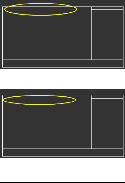
Turn on your computer and press Del to enter BIOS Setup during POST (Power-On Self Test). If you want to create RAID, select IDE Function Setup under the Integrated Peripherals menu and then press ENTER (Figure 1). Change the SATA Primary Master RAID and SATA Secondary Master RAID items to Enabled (Disabled by default) (Figure 2). Skip this step and leave the two items to Disabled by default if you do not want to create RAID.
CMOS Setup Utility-Copyright (C) 1984-2004 Award Software
Integrated Peripherals
|
IDE Function Setup |
[Press Enter] |
Item Help |
|||
|
On-Chip Primary PCI IDE |
[Enabled] |
|
Menu Level} |
||
|
On-Chip Secondary PCI IDE |
[Enabled] |
|
|
|
|
|
USB Host Controller |
[V1.1+V2.0] |
|
|
||
|
USB Keyboard Support |
[Disabled] |
|
|
|
|
|
USB Mouse Support |
[Disabled] |
|
|
|
|
|
Serial-ATA 2(Internal PHY) |
[Enabled] |
|
|
|
|
|
AC97 Audio |
|
[Auto] |
|
|
|
|
On-Chip LAN(nVIDIA) |
[Auto] |
|
|
|
|
|
Onboard Serial ATA |
[Enabled] |
|
|
|
|
|
Serial ATA Function |
[RAID] |
|
|
|
|
|
Onboard 1394 |
|
[Enabled] |
|
|
|
|
Onboard LAN Control |
[Enabled] |
|
|
|
|
|
Onboard LAN Boot ROM |
[Disabled] |
|
|
|
|
|
Onboard Serial Port 1 |
[3F8/IRQ4] |
|
|
||
|
Onboard Serial Port 2 |
[2F8/IRQ3] |
|
|
||
|
Onboard Parallel Port |
[378/IRQ7] |
|
|
||
|
Parallel Port Mode |
[SPP] |
|
|
|
|
x |
ECP Mode Use DMA |
3 |
|
|
|
|
higf: Move |
Enter: Select |
+/-/PU/PD: Value |
F10: Save |
ESC: Exit |
F1: General Help |
|
|
F5: Previous Values |
F6: Fail-Safe Defaults |
|
F7: Optimized Defaults |
||
Figure 1 (This BIOS setup screen is captured from GA-K8NSNXP-939, BIOS ver.: D24)
The BIOS Setup menus described in this section may not show the exact settings for your motherboard. The actual BIOS Setup menu options you will see shall depend on the motherboard you have and the BIOS version.
CMOS Setup Utility-Copyright (C) 1984-2004 Award Software
IDE Function Setup
IDE RAID |
[Enabled] |
Item Help |
IDE Channel 0 Master RAID |
[Disabled] |
Menu Level} |
IDE Channel 0 Slave RAID |
[Disabled] |
|
IDE Channel 1 Master RAID |
[Disabled] |
|
IDE Channel 1 Slave RAID |
[Disabled] |
|
SATA Primary Master RAID |
[Enabled] |
|
SATA Secndry Master RAID |
[Enabled] |
|
higf: Move |
Enter: Select |
+/-/PU/PD: Value |
F10: Save |
ESC: Exit |
F1: General Help |
F5: Previous Values |
F6: Fail-Safe Defaults |
|
F7: Optimized Defaults |
||
Figure 2
- 3 - SATA Hard Drive Configurations (nForce series)
Step 2:
Later, select Hard Disk Boot Priority under the Advanced BIOS Features menu. In the Hard Disk Boot Priority submenu, select the model of the SATA hard drive onto which you intent to install Microsoft Windows 2000/XP (Figure 3).
CMOS Setup Utility-Copyright (C) 1984-2004 Award Software
Hard Disk Boot Priority
1. CH2 M. |
: |
S_ATA1-ST3120026AS |
Item Help |
2. CH3 M. |
: |
S_ATA2-ST3120026AS |
Menu Level }} |
3. Bootable Add-in Cards |
|
|
|
|
|
|
Use <h> or <i> to |
|
|
|
select a device, then |
|
|
|
press <+> to move it |
|
|
|
up, or <-> to move it |
|
|
|
down the list. Press |
|
|
|
<ESC> to exit this |
|
|
|
menu. |
hi: Move |
PU/PD/+/-: Change Priority |
F10: Save |
ESC: Exit |
|
|
Figure 3 |
|
Step 3:
Set First Boot Device under the Advanced BIOS Features menu to CDROM to boot from CD-ROM drive after system restarts (Figure 4).
CMOS Setup Utility-Copyright (C) 1984-2004 Award Software
Advanced BIOS Features
} |
Hard Disk Boot Priority |
[Press Enter] |
Item Help |
|
First Boot Device |
[CDROM] |
Menu Level} |
|
Second Boot Device |
[Hard Disk] |
|
|
Third Boot Device |
[CDROM] |
|
|
Boot Up Floopy Seek |
[Disabled] |
|
|
Password Check |
[Setup] |
|
|
Flexible AGP 8X |
[Auto] |
|
|
Init Display First |
[AGP] |
|
higf: Move |
Enter: Select |
+/-/PU/PD: Value |
F10: Save |
ESC: Exit |
F1: General Help |
F5: Previous Values |
F6: Fail-Safe Defaults |
|
F7: Optimized Defaults |
||
Figure 4
Step 4:
Save and exit BIOS Setup.
SATA Hard Drive Configurations (nForce series) - 4 -
(3) Configuring RAID set in RAID BIOS
Enter the RAID BIOS setup utility to configure a RAID array. Skip this step and proceed to Section 4 if you do not want to create RAID.
Step 1:
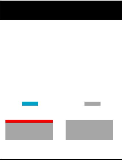
After the POST memory test begins and before the operating system boot begins, look for a message which says "Press F10 to enter RAID setup utility" (Figure 5). Hit the F10 key to enter the RAID BIOS setup utility.
NVIDIA RAID IDE ROM BIOS 4.22
Copyright (C) 2003 NVIDIA Corp.
Detecting array ...
Press F10 to enter RAID setup utility ...
Figure 5
Step 2
The Define a New Array screen is the first option screen when you enter the NVIDIA RAID setup utility. (Figure 6). You can press the TAB key to highlight through options. The following below is an example of RAID 0 array creation.
Step 3:
In the RAID Mode field, use the UP or DOWN ARROW key to select a RAID mode. The supported RAID modes include Mirroring (default), Striping, Stripe Mirroring, and Spanning.
Step 4:
If RAID 0 is selected, you can manually set the striping block size. In the Striping Block field, use the UP or DOWN ARROW key to set the Striping Block size. The KB is the standard unit of Striping Block size. We recommend you leaving it to the default setting--Optimal (64K). The size range is from 4K to 128K.
|
|
NV I D I A |
R A I D Ut il it y Ma y 10 |
2 00 4 |
|
||
|
|
- D e f i n e a N e w A r r a y - |
|
|
|||
R A I D M o d e : M i r r o r i n g |
|
S t r ip in g Bl o c k: O p t im a l |
|||||
F r e e D is ks |
|
|
A r r a y D i s k s |
|
|||
L o c |
D i s k M o d e l N a m e |
|
L o c |
D i s k M o d e l N a m e |
|||
1 . 0 . M S T 3 1 20 0 2 6 A S |
|
|
|
|
|
||
1 . 1 . M S T 3 1 20 0 2 6 A S |
[g ] |
A d d |
|
|
|
||
|
|
|
|
|
|
||
|
|
|
[f ] |
D e l |
|
|
|
[ F 6] |
Bac k |
[ F 7] F in is h |
[ TA B] N a viga t e |
[ h i ] |
S e le c t |
[ E N TE R ] P o p u p |
|
|
|
|
|
|
|
|
|
Figure 6
- 5 - SATA Hard Drive Configurations (nForce series)
 Loading...