


8I845GE-RZ / 8I845GE-RZ-C
Intel® Pentium® 4 Processor Motherboard
User's Manual
Rev. 1001
12ME-I845GERZ-1001
Copyright
© 2004 GIGABYTE TECHNOLOGY CO., LTD
Copyright by GIGA-BYTE TECHNOLOGY CO., LTD. ("GBT"). No part of this manual may be reproduced or transmitted in any from without the expressed, written permission of GBT.
Trademarks
Third-party brands and names are the property of their respective owners.
Notice
Please do not remove any labels on motherboard, this may void the warranty of this motherboard.
Due to rapid change in technology, some of the specifications might be out of date before publication of this booklet.
The author assumes no responsibility for any errors or omissions that may appear in this document nor does the author make a commitment to update the information contained herein.

Mother Board
8I845GE-RZ
Motherboard
8I845GE-RZ
Oct. 15 ,2004
Oct. 15, 2004

Preparing Your Computer
Computer motherboards and expansion cards contain very delicate Integrated Circuit (IC) chips. To protect them against damage from static electricity, you should follow some precautions whenever you work on your computer.
1.Unplug your computer when working on the inside.
2.Use a grounded wrist strap before handling computer components. If you do not have one, touch both of your hands to a safely grounded object or to a metal object, such as the power supply case.
3.Hold components by the edges and try not touch the IC chips, leads or connectors, or other components.
4.Place components on a grounded antistatic pad or on the bag that came with the components whenever the components are separated from the system.
5.Ensure that the ATX power supply is switched off before you plug in or remove the ATX power connector on the motherboard.
Installing the motherboard to the chassis
If the motherboard has mounting holes, but they don't line up with the holes on the base and there are no slots to attach the spacers, do not become alarmed you can still attach the spacers to the mounting holes. Just cut the bottom portion of the spacers (the spacer may be a little hard to cut off, so be careful of your hands). In this way you can still attach the motherboard to the base without worrying about short circuits. Sometimes you may need to use the plastic springs to isolate the screw from the motherboard PCB surface, because the circuit wire may be near by the hole. Be careful, don't let the screw contact any printed circuit write or parts on the PCB that are near the fixing hole, otherwise it may damage the board or cause board malfunctioning.

English
Table of Content |
|
Chapter 1 Introduction .................................................................................................... |
5 |
Features Summary ..................................................................................................................... |
5 |
8I845GE-RZ Series Motherboard Layout ..................................................................................... |
7 |
Block Diagram ............................................................................................................................ |
8 |
Hardware Installation Process ..................................................................................................... |
9 |
Step 1: Install the Central Processing Unit (CPU) ....................................................................... |
9 |
Step 1-1: CPU Installation .................................................................................................. |
10 |
Step 1-2: CPU Cooling Fan Installation .............................................................................. |
10 |
Step 2: Install Memory Modules ................................................................................................ |
11 |
Step 3: Install AGP Card .......................................................................................................... |
12 |
Step 4: Install I/O Peripherals Cables ....................................................................................... |
12 |
Step 4-1: I/O Back Panel Introduction ................................................................................ |
12 |
Step 4-2: Connectors Introduction ....................................................................................... |
13 |
Chapter 2 BIOS Setup .................................................................................................. |
21 |
The Main Menu (For example: BIOS Ver. : F1) ........................................................................ |
21 |
Standard CMOS Features ........................................................................................................ |
23 |
Advanced BIOS Features ......................................................................................................... |
25 |
Integrated Peripherals ............................................................................................................... |
27 |
Power Management Setup ........................................................................................................ |
29 |
PnP/PCI Configurations ............................................................................................................ |
31 |
PC Health Status ...................................................................................................................... |
32 |
Frequency/Voltage Control ........................................................................................................ |
33 |
Top Performance ....................................................................................................................... |
34 |
Load Fail-Safe Defaults .............................................................................................................. |
34 |
Load Optimized Defaults ............................................................................................................ |
35 |
Set Supervisor/User Password ................................................................................................ |
35 |
Save & Exit Setup .................................................................................................................... |
36 |
Exit Without Saving .................................................................................................................. |
36 |
Chapter 3 Driver Installation ......................................................................................... |
37 |
8I845GE-RZ Series Motherboard |
- 4 - |

Chapter 1 Introduction
Features Summary
CPU |
|
y |
Socket 478 for Intel® Pentium® 4 (Northwood, Prescott(note 1)) processor |
|
|
|
with HT Technology |
|
|
y |
Supports 533/400MHz FSB |
|
|
y L2 cache varies with processors |
|
|
|
|
|
Chipset |
|
y |
North Bridge:Intel® 845GE |
|
|
y South Bridge: Intel® ICH4 |
|
Memory |
|
y |
3 184-pin DDR sockets |
|
|
y Supports DDR333/DDR266 DIMMs(note 2) |
|
|
|
y Supports up to 2GB (Max.) |
|
|
|
y Supports only 2.5V DDR SDRAM |
|
|
|
|
|
Slots |
|
y |
1 AGP slot 4X (1.5V) device support |
|
|
y |
5 PCI slots |
|
|
|
|
IDE Connections |
y |
2 IDE connection (UDMA 33/ATA 66/ATA 100), allows connection of 4 |
|
|
|
|
IDE devices |
|
|
|
|
FDD Connections |
y |
1 FDD connection, allows connection of 2 FDD devices |
|
Peripherals |
y |
1 parallel port supporting Normal/EPP/ECP mode |
|
|
|
y 1 VGA port, 1 COMA port, onboard COMB connection |
|
|
|
y 6 USB 2.0/1.1 ports (rear x 2, front x 4 via cable) |
|
|
|
y 1 front audio connector |
|
|
|
y 1 PS/2 keyboard port |
|
|
|
y 1 PS/2 mouse port |
|
|
|
|
|
Onboard |
VGA |
y |
Built-in Intel® 82845GE Chipset |
Onboard |
LAN |
y |
RLT8100C* |
|
|
y |
1 RJ45 port* |
Onboard Audio |
y |
C-Media 9761A CODEC |
|
|
|
y Supports Line In ; Line Out ; MIC In |
|
|
|
y Supports 2 / 4 / 6 channel audio |
|
|
|
y Supports SPDIF In/Out connection |
|
|
|
y CD In/AUX In/Game Port |
|
|
|
|
|
BIOS |
|
y |
Use of licensed AWARD BIOS |
|
|
y |
Supports Q-Flash |
|
|
|
|
to be continued......
(Note 1) Prescotts processors with up to 533MHz FSB are supported.
(Note 2) Due to (Intel 845PE/GE/GV) chipset architecture limitation, DDR333 memory modules are supported only when you install a Pentium 4 processor with 533MHz FSB.
A Pentium 4 processor with 400MHz FSB will support DDR266 memory modules. "*" For 8I845GE-RZ only.
- 5 - |
Introduction |
English

English
I/O Control |
y |
IT8712 |
|
|
|
Hardware Monitor |
y |
CPU / System fan speed detection |
|
y |
System voltage detection |
|
y |
CPU temperature detection |
|
y CPU/System fan fail warning |
|
|
y |
CPU overheating warning |
|
|
|
Additional Features |
y |
Supports EasyTune 4 |
|
y |
Supports @BIOS |
|
|
|
Form Factor |
y |
ATX form factor; 29.5cm x 21cm |
Please set the CPU host frequency in accordance with your processor's specifications. We don't recommend you to set the system bus frequency over the CPU's specification because these specific bus frequencies are not the standard specifications for CPU, chipset and most of the peripherals. Whether your system can run under these specific bus frequencies properly will depend on your hardware configurations, including CPU, Chipsets, Memory, Cards….etc.
8I845GE-RZ Series Motherboard |
- 6 - |

8I845GE-RZ Series Motherboard Layout
KB_MS |
CPU_FAN |
|
COMA |
|
|
|
LPT |
|
VGA |
|
|
LINEIN OUT INLINE |
|
ATX_12V |
Game |
SUR_CEN |
|
|
|
|
MIC_ |
|
F_AUDIO |
|
|
|
USB |
LAN* |
|
|
|
RTL8100C* |
CODEC |
CD_IN |
AUX_IN |
C- |
712 |
|
TI8 |
|
|
# |
|
|
|
|
SPDIF_IO |
Socket 478
Intel 845GE
AGP
PCI1
PCI2
PCI3
PCI4
PCI5
CI
F_USB1 F_USB2
COMB
ATX
8I845GE-RZ
DDR1 |
DDR2 |
DDR3 |
FDD |
|
|
|
CLR_CMOS
SYS _FAN
Intel ICH4
BAT
BIOS
IDE2
IDE1
F_PANEL PWR_LED
"*" For 8I845GE-RZ only. "#" For 8I845GE-RZ-C only.
- 7 - |
Introduction |
English
English
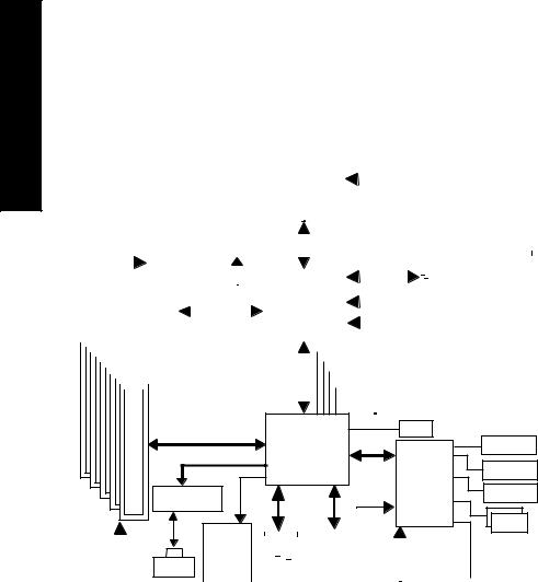
Block Diagram
|
|
|
|
|
|
|
|
|
|
|
|
|
|
|
|
|
|
|
|
|
|
|
|
|
Socket 478 |
|
|
|
|
CPUCLK+/- (100/133MHz) |
|
|
|
|||||||||||||||
|
|
|
|
|
|
|
|
|
|
|
|
|
|
|
|
|
|
|
|
|
|
|
|
|
|
|
|
|
|
|
|
|
|
|
|
|
|
|
|
|
|
|
||||||
|
|
|
|
|
|
|
|
|
|
|
|
|
|
|
|
|
|
|
|
|
|
|
|
|
Processor |
|
|
|
|
|
|
|
|
|
|
|
|
|
|
|
|
|
|
|||||
|
|
|
|
|
|
|
|
|
|
|
|
|
|
|
AGP 4X |
|
|
|
|
|
|
|
|
|
|
|
|
|
|
|
|
|
|
|
|
|
|
|
|
|||||||||
|
|
AGPCLK |
|
|
|
|
|
|
|
|
VGA Port |
|
|
|
|
|
Host |
|
|
|
|
|
|
|
|
266/333MHz |
|
|
|
|||||||||||||||||||
|
|
|
|
|
|
|
|
|
|
|
|
|
|
|
|
|
|
|
|
|
|
|
|
|
|
|||||||||||||||||||||||
|
|
|
(66MHz) |
|
|
|
|
|
|
|
|
|
|
|
|
Interface |
|
|
|
|
|
|
|
|
|
|
|
|||||||||||||||||||||
|
|
|
|
|
|
|
|
|
|
|
|
|
|
|
|
|
|
|
|
|
|
|
|
|
|
|
|
|
|
|
|
|
|
|
|
|
|
|
|
|
|
|
DDR RAM |
|
|
|
||
|
|
|
|
|
|
|
|
|
|
|
|
|
|
|
|
|
|
|
|
|
|
|
|
|
Intel 82845GE |
|
|
|
|
GMCHCLK(66MHz) |
|
|
|
|||||||||||||||
|
|
|
|
|
|
|
|
|
|
|
|
|
|
|
|
|
|
|
|
|
|
|
|
|
|
|
|
|
|
|
|
|
|
|
|
|
|
|
|
|
|
|
||||||
|
|
|
|
5 PCI |
|
|
|
|
|
|
|
|
|
|
|
|
|
|
|
|
HCLK+/- (100/133MHz) |
|
|
|
||||||||||||||||||||||||
|
|
|
|
|
|
|
|
|
|
|
|
|
|
|
|
|
|
|
|
|
|
|
|
|
|
|
|
|
||||||||||||||||||||
|
|
|
|
|
|
|
|
|
|
|
|
|
|
|
|
|
|
|
|
|
|
|
|
|
|
66 MHz |
|
|
|
|
||||||||||||||||||
|
|
|
|
|
|
|
|
|
|
|
|
|
|
|
|
|
|
|
|
|
|
|
|
|
|
|
|
|
||||||||||||||||||||
|
|
|
|
|
|
|
|
|
|
|
|
|
|
|
|
|
|
|
|
|
|
|
|
|
|
|
|
|
||||||||||||||||||||
|
|
|
|
|
|
|
|
|
|
|
|
|
|
|
|
|
|
|
|
|
|
|
|
|
|
|
|
|
|
|
|
|
|
|
|
|
|
|||||||||||
|
|
|
|
|
|
|
|
|
|
|
|
|
|
|
|
|
|
|
|
|
|
|
|
|
|
|
|
|
|
|
|
|
|
|
|
|
33 |
MHz |
|
|
|
|||||||
|
|
|
|
|
|
|
|
|
|
|
|
|
|
|
|
|
|
|
|
|
|
|
|
|
|
|
|
|
|
|
|
|
|
|
|
|
|
14.318 MHz |
|
|
|
|||||||
|
|
|
|
|
|
|
|
|
|
|
|
|
|
|
|
|
|
|
|
|
|
|
|
|
|
|
|
|
|
|
|
|
|
|
|
|
|
48 MHz |
|
|
|
|||||||
|
|
|
|
|
|
|
|
|
|
|
|
|
|
|
|
|
|
|
|
|
|
|
|
|
|
|
|
|
|
|
|
|
|
|
|
|
|
|
|
|
||||||||
|
|
|
|
|
|
|
|
|
|
|
|
|
|
|
|
|
|
|
|
|
|
|
|
|
|
|
|
|
|
|
|
|
|
|
|
|
|
|||||||||||
|
|
|
|
|
|
|
|
|
|
|
|
|
|
|
|
|
|
|
|
|
|
|
|
|
|
|
|
|
|
|
|
|
|
|
|
|
|
|
|
|
||||||||
|
|
|
|
|
|
|
|
|
|
|
|
|
|
|
|
|
|
|
|
|
|
|
|
|
|
|
|
|
|
|
|
|
|
|
|
|
|
|
|
|
|
|
|
|
|
|
|
|
|
|
|
BIOS |
|
|
Intel ICH4 |
Game Port |
|
|
|
|
|
Link |
LPC BUS |
Floppy |
|
|
IT8712 |
|
RTL8100C* |
AC97 |
24 MHz |
LPT Port |
|
|
||
|
|
|
PCICLK |
|
|
AC97 |
|
|
|
|
|
|
|
|
|
|
|
|
|
|
|
|
|
|
|
|
|
COM |
|||||||
|
|
|
|
|
|
|
|
|
|
|
|
|
|
|
|
|
|
|
|
|
|
|
||||||||||
|
CODEC |
|
|
|
|
|
|
|
|
|
|
|
|
|
|
|
|
|
|
|
|
|
Ports |
|||||||||
(33MHz) |
RJ45* |
|
|
|
|
|
|
|
|
|
|
|
|
|
|
|
|
|
|
|
|
|
||||||||||
|
|
|
|
|
|
|
|
|
|
|
|
|
|
|
|
|
|
|
|
|
|
|
|
|
|
|
|
|
|
|||
|
|
|
|
|
|
|
|
6 USB |
|
|
|
|
|
|
|
|
33 MHz |
|
|
|
|
|
|
|||||||||
|
|
|
|
|
|
|
|
|
|
|
ATA33/66/100 |
|
|
|
|
|
|
|||||||||||||||
|
|
|
|
|
|
|
|
|
|
|
Ports |
|
|
|
IDE Channels |
|
|
|
|
|
|
|
|
|||||||||
|
|
|
|
|
|
|
|
|
|
|
|
|
|
|
|
|
|
|
|
|
|
|||||||||||
|
|
|
|
|
|
|
|
|
|
|
|
|
|
|
|
|
|
|
|
|
|
|
|
PS/2 |
||||||||
|
|
|
MIC LINE-IN OUT-LINE |
|
|
|
|
|
|
|
|
|
|
|
|
|||||||||||||||||
|
|
|
|
|
|
|
|
|
|
|
|
|
|
KB/Mouse |
||||||||||||||||||
|
|
|
|
|
|
|
|
|
|
|
|
|
|
|
|
|
|
|
|
|
|
|
|
|
|
|
|
|||||
"*" For 8I845GE-RZ only.
8I845GE-RZ Series Motherboard |
- 8 - |

Hardware Installation Process
To set up your computer, you must complete the following steps:
Step 1- Install the Central Processing Unit (CPU)
Step 2- Install memory modules
Step 3- Install expansion cards
Step 4- Install I/O Peripherals cables
Step 4 |
Step 1 |
Step 2 |
|||
|
|
|
|
|
|
|
|
|
|
|
|
|
|
|
|
|
|
|
|
|
|
|
|
|
|
|
|
|
|
Step 4
Step 4
Step 3
Step 1: Install the Central Processing Unit (CPU)
Before installing the CPU, please comply with the following conditions: 1. Please make sure that the motherboard supports the CPU.
2. Please take note of the one indented corner of the CPU. If you install the CPU
in the wrong direction, the CPU will not insert properly. If this occurs, please change the insert direction of the CPU.
3. Please add an even layer of heat sink paste between the CPU and heatsink.
4. Please make sure the heatsink is installed on the CPU prior to system use, otherwise overheating and permanent damage of the CPU may occur.
5. Please set the CPU host frequency in accordance with the processor specifications. It is not recommended that the system bus frequency be set beyond hardware specifica tions since it does not meet the required standards for the peripherals. If you wish to set the frequency beyond the proper specifications, please do so according to your hard ware specifications including the CPU, graphics card, memory, hard drive, etc.
HT functionality requirement content :
Enabling the functionality of Hyper-Threading Technology for your computer system requires all of the following platform components:
- CPU: An Intel® Pentium 4 Processor with HT Technology
-Chipset: An Intel® Chipset that supports HT Technology
-BIOS: A BIOS that supports HT Technology and has it enabled
-OS: An operation system that has optimizations for HT Technology
|
|
|
- 9 - |
Hardware Installation Process |
|
English
English
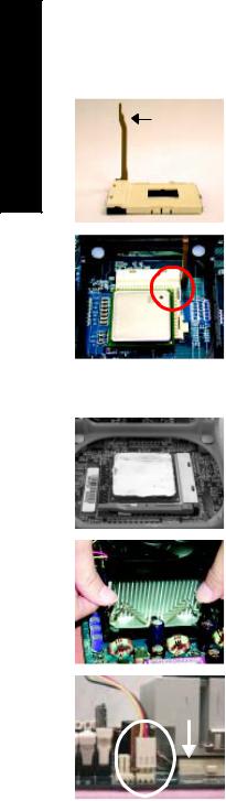
Step 1-1: CPU Installation
Figure 1.
Socket |
Pull the rod to the 90-degree directly. |
|
Actuation |
||
|
||
Lever |
|
Figure 2.
Locate Pin 1 in the socket and look for a (golden) cut edge on the CPU upper corner. Insert the CPU into the socket. (Do not force the CPU into the socket.) Then move the socket lever to the locked position while holding pressure on the center of the CPU.
Step 1-2: CPU Cooling Fan Installation
Figure 1.
Apply the thermal tape(or grease) to provide better heat conduction between your CPU and cooling fan.
Figure 2.
Fasten the cooling fan supporting-base onto the CPU socket on the motherboard.
Figure 3.
Make sure the CPU fan is plugged to the CPU fan connector, and then the installation is completed.
8I845GE-RZ Series Motherboard |
- 10 - |
Step 2: Install Memory Modules
Before installing the memory modules, please comply with the following conditions:
1. Please make sure that the memory used is supported by the motherboard. It is recommended that memory of similar capacity, specifications and brand be used.
2.Before installing or removing memory modules, please make sure that the computer power is switched off to prevent hardware damage.
3.Memory modules have a foolproof insertion design. A memory module can be installed in only one direction. If you are unable to insert the module, please switch the direction.
4.Because of chipset (Intel 845PE/GE) limitations, DDR333 memory modules are supported only when you install a Pentium 4 processor with 533MHz FSB. A Pentium 4 processor with 400MHz FSB will support DDR266 memory modules.
The motherboard has 3 dual inline memory module (DIMM) sockets. The BIOS will automatically detects memory type and size. To install the memory module, just push it vertically into the DIMM socket. The DIMM module can only fit in one direction due to the notch. Memory size can vary between sockets.
English
notch
DDR memory module
Fig.1
The DIMM socket has a notch, so the DIMM memory module can only fit in one direction. Insert the DIMM memory module vertically into the DIMM socket. Then push it down.
Fig. 1
Fig.2
Close the plastic clip at both edges of the DIMM sockets to lock the DIMM module.
Reverse the installation steps when you wish to remove the DIMM module.
Fig. 2
|
|
|
- 11 - |
Hardware Installation Process |
|
English
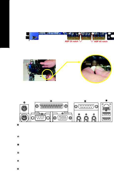
Step 3: Install AGP Card
1. Read the related expansion card's instruction document before installing the expansion card into the computer.
2. Please make sure your AGP card is AGP 4X (1.5V).
3. Please carefully pull out the small whitedrawable bar at the end of the AGP slot when you try to install/ Uninstall the AGP card. Please align the AGP card to the onboard AGP slot and press firmly down on the slot .Make sure your AGP card is locked by the small whitedrawable bar.
AGP Card
Step 4: Install I/O Peripherals Cables
Step 4-1: I/O Back Panel Introduction
 *
*
PS/2 Keyboard and PS/2 Mouse Connector
To install a PS/2 port keyboard and mouse, plug the mouse to the upper port (green) and the keyboard to the lower port (purple).
Parallel Port
The parallel port allows connection of a printer, scanner and other peripheral devices.
Serial Port
Devices like mouses, modems, and etc. can be connected to Serial port.
VGA Port
Monitor can be connected to VGA port.
Game/MIDI port
This connector supports joystick, MIDI keyboard and other related audio devices.
Line Out (Front Speaker Out)
Connect the stereo speakers, earphone or front surround channels to this connector.
"*" For 8I845GE-RZ only.
8I845GE-RZ Series Motherboard |
- 12 - |
 Loading...