

Page 1
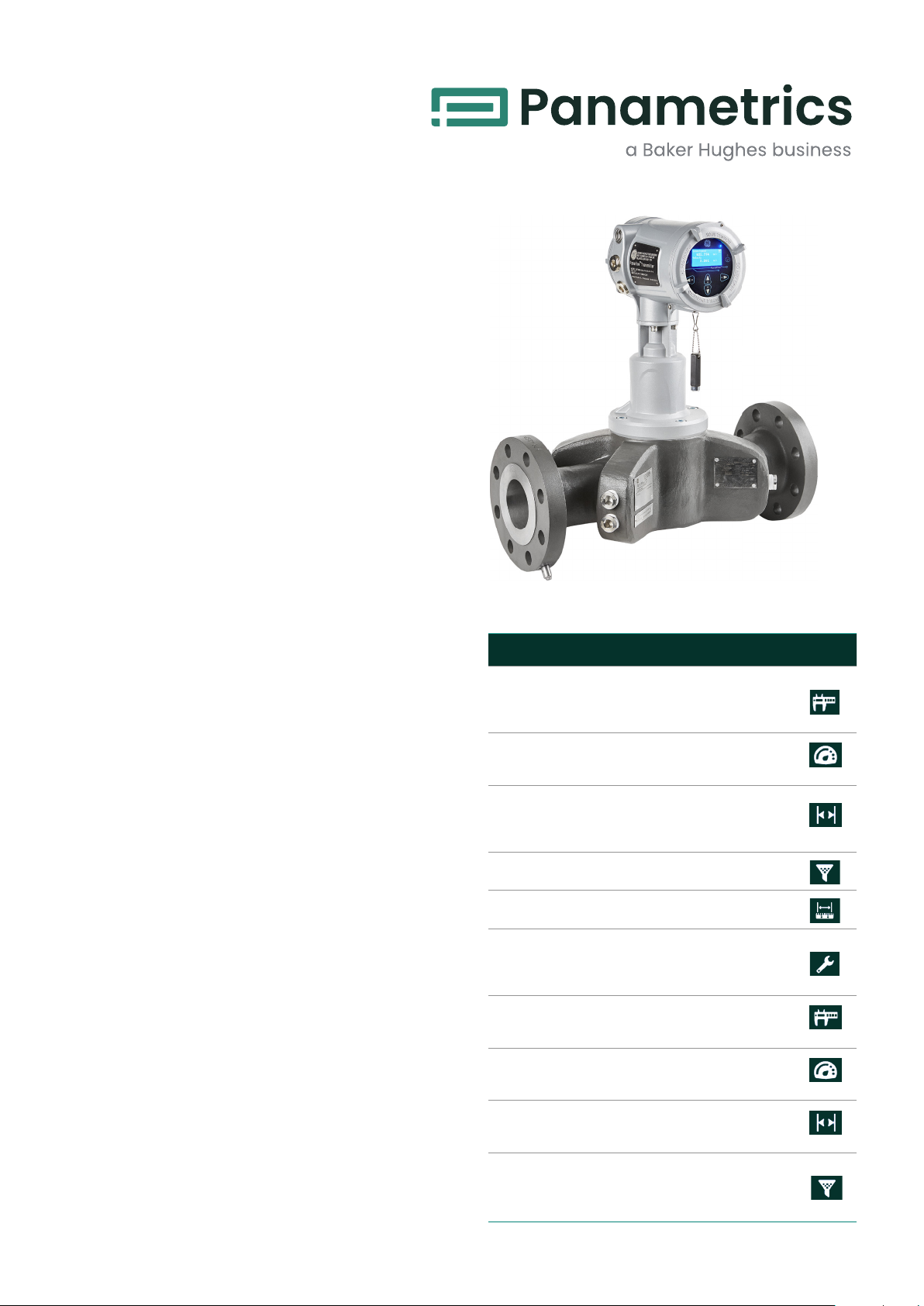
PanaFlow Z3
Panametrics Ultrasonic
Flow Meter for Liquids
The PanaFlow Z3 represents the latest
generation of Panametrics ultrasonic flow
meters. It is a three-path meter designed
specifically for dependable, accurate and
repeatable flow measurement of process
liquids. With a sleek industrial design and
ultra-reliable electronics, it provides operators
a cost-effective choice when measurement
accuracy and reliability are critical. The
capabilities of the PanaFlow Z3 make it the
right meter for a number of industries and
applications, including:
Industries
• Upstream, midstream and downstream oil and gas
• Chemical
• Petrochemical
• Refining
• Power generation
• District energy/HVAC
• Water/wastewater
Applications
• Process control and monitoring
• Allocation measurement
• Batching and blending
• Transfer lines
• Cooling water lines
• Pipeline metering
• Loading/unloading
• Plant utilities
• Tank farms
• Irrigation
• Crude refined products
Panametrics.com
Features & Benefits
Features Benefits
No drifting, no
periodic calibration
required
No pressure drop
No restriction in the
pipe
No filters or
strainers
Bi-directional
measurement
No moving parts
Field replaceable
transducers
All cast design
Explosion-proof
transducer design
Full ultrasonic
product line
No loss of process control, no
downtime, no expense from
calibration, and optimization
of assets.
No wasted energy from
running a pump or need to
purchase a larger size pump
Contamination will not
affect meter’s measurement
(drifting) or cause any
damage to meter
No maintenance cost
No additional meters
required
No loss of process control, no
downtime, no expense from
calibration, and optimization
of assets.
No risk in measurement, no
shutdown costs for transducer
maintenance
Precision machined flowcell
minimizes flow disturbance for
better accuracy
More power to transducers
at higher voltages, less risk of
attenuation in fluid
Meets more needs with
full product portfolio; one
manufacturer for ultrasonic
flow meters
Page 2
Reliable flow measurement that is
easy on your budget
The PanaFlow Z3 is a three-path, wetted ultrasonic flow
meter that brings together all of the advantages of
ultrasonic technology at a very affordable value. Unlike
other flow measurement technologies, the PanaFlow Z3
does not require maintenance since it does not have
any obstruction in the flow path that could clog the
process line or moving parts to be damaged by the
flowing fluid.
Also, due to the inherent nature of our ultrasonic flow
measurement, the PanaFlow Z3’s measurement is not
affected by changing process conditions (temperature,
pressure, and conductivity) and does not drift over
time, which eliminates the requirement for periodic
calibration. Without requirements for maintenance and
calibration, the PanaFlow Z3 offers high performance
with a low cost of ownership.
What is the PanaFlow Z3?
The PanaFlow Z3 consists of the Panametrics PanaFlow
XMT1000 electronics, three pairs of LX transducers, and
sensor body. The XMT1000 is our latest ultrasonic flow
transmitter with state-of-the-art flow measurement
capability in a rugged enclosure certified for use in
hazardous areas. The LX transducer system is our latest
advancement in ultrasonic transducer technology and
provides accurate, drift-free and obstructionless flow
measurement.
Fast and Easy Installation
Installation of wetted systems can be difficult and if
they are not installed with precision and with close
attention to detail, the reliability and accuracy of the
system may not meet specifications. With the new
PanaFlow Z3 system, the assembly work is done at
the factory. The necessary components are already
installed, so all the user needs to do is to bolt the end
flanges into place.
Transit Time Flow Measurement
In this method, two transducers serve as both ultrasonic
signal generators and receivers. They are in acoustic
communication with each other, meaning the second
transducer can receive ultrasonic signals transmitted
by the first transducer and vice versa.
In operation, each transducer functions as a
transmitter, generating a certain number of acoustic
pulses, and then as a receiver for an identical number
of pulses. The time interval between transmission and
reception of the ultrasonic signals is measured in both
directions. When the liquid in the pipe is not flowing,
the transit time downstream equals the transit time
upstream. When the liquid is flowing, the transit time
downstream is less than the transit time upstream.
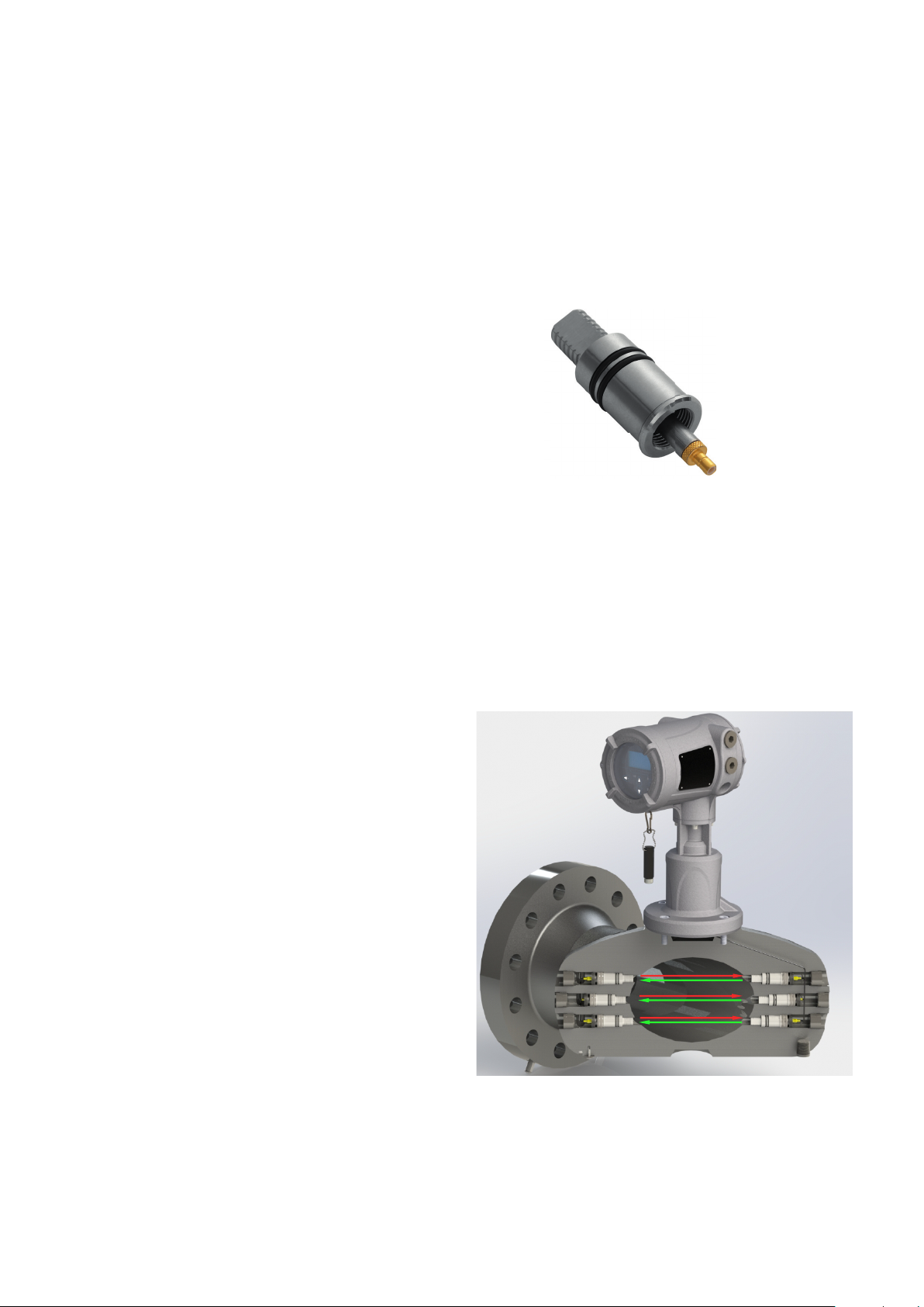
LX Transducer
The LX transducer system consists of our new
integrated LX transducers and our uniquely engineered
buffers. The design of this system allows for the safe
insertion and removal of the LX transducers at any time
without isolating the flow meter, shutting down the
process or using any special tools. Together with the
XMT1000 electronics and LX transducer, the uniquely
designed meter body provides a clean and compact
flow meter system.
The difference between the downstream and upstream
transit times is proportional to the velocity of the flowing
liquid, and its sign indicates the direction of flow.
Transit Time Flow Measurement
Page 3

Overall Operation and
Performance
Fluid Types
Liquids: acoustically conductive fluids, including most
clean liquids, and many liquids with small amounts of
entrained solids or gas bubbles.
Flow Measurement
Correlation transit time model
Accuracy
3 to 24 in (80 to 600 mm)
• ±0.25% of reading for velocities above 1.6 ft/s (0.5
m/s)
• ±1.25 mm/s for velocities below 1.6 ft/s (0.5 m/s)
2 in (50 mm)
• ±0.5% of reading for velocities above 1.6 ft/s (0.5
m/s)
• ±2.5 mm/s for velocities below 1.6 ft/s (0.5 m/s)
Accuracy statement assumes measurement of a
single phase homogenous liquid with a fully developed
symmetrical flow profile passing through the meter
(typically 10 diameters upstream and 5 diameters
downstream of straight pipe run).
Applications with piping arrangements that create an
asymmetrical flow profile may require extended piping
straight runs and/or flow conditioning for the meter to
perform to this specification.
Calibration
All meters are water calibrated at ambient conditions
and include a calibration certificate.
• 3 points as found 2, 5, and 10 ft/s (0.6, 1.5 and 3 m/s)
and 2 points as left 3 and 7 ft/s (0.9 and 2.1 m/s)
Repeatability
• ±0.15% of reading 3 to 24 in (80 to 600 mm)
• ±0.2% of reading 2 in (50 mm)
Range (Bidirectional)
-82 to 82 ft/s (-25 to 25 m/s)
Meter Body/Transducer System
Meter Body Materials
• Low temperature carbon steel: ASTM SA352 Gr. LCC
• Stainless steel: ASTM SA351 Gr. CF8M
• Duplex stainless steel: ASTM SA995 GR. CD3MWCuN
Transducer System and Material
• LX transducers with inserts
• 316 SS or A479 UNS S32760 (Duplex)
• Wetted components Seals:
• FKM or EPDM
Process Fluid Temperature Range
• Local mount: -40°F to 302°F (-40°C to 150°C*)
• Remote mount: -40°F to 302°F (-40°C to 150°C)
*Maximum process temperature is 203°F (95°C) when
additional analog input/output options are selected
Pressure Range
Up to maximum allowable flange operating pressure at
temperature per ASME B16.5 or EN1092-1
Piping Design
• ASME B31.3
• NACE MR0103/MR0175
• PED PER B31.3, CAT II, A2
• CRN
Weights and Dimensions
See Drawings 712-2166 (local mount) and 712-2167
(remote mount) for details.
Drawing Drawing Description
712-2166 Outline & installation, Z3, 2 – 24 in. (50
712-2167 Outline & installation, Z3, 2 – 24 in. (50
– 600 mm) flow meter system, local
mount
– 600 mm) flow meter system, remote
mount
Page 4

Transmitter
Enclosures
Powder coated aluminum or stainless
steel (SS316) conformal coated
Classifications
US/CAN: Class I, Division 1, Groups B, C, D;
Class I, Zone 1, Ex db IIB+H2 T6...150C;
IP 66/67 Type 4X
SINGLE SEAL
ATEX/IECEx: Ex db IIB+H2 T6...150C FISCO outputs
Ta = -40°C to +65°C, IP 66/67
Operating: -40°F to 149°F (-40°C to +65°C*)
Storage: -40°F to 158°F (-40°C to 70°C)
Keypad
Built-in magnetic, six-button, lockable keypad
Cable Entries
¾” NPT
M20 Adapters
Power Supplies
Universal 100-240 VAC 50/60 Hz ±10% or 12 to 28 VDC
(15W max, 7W typical)
Standard Inputs/Outputs
• One 4 to 20 mA isolated output, 600 Ohm
maximum load, NAMUR NE43
• One additional output, may be configured as either
a pulse or frequency output.
*Maximum ambient temperature is 60°C (140°F when
foundation fieldbus option selected)
Transmitter Mounting
Local or remote mounting
Paths
Three paths : 3 to 24 in (80 to 600 mm)
Two paths : 2 in (50 mm)
Display
English
128 x 64 mono-color LCD display, configurable for single
or dual measurement parameters
Optional Inputs/Outputs
Analog and digital I/O are available in specific
combinations. See ordering information below for
details:
• Two additional 4 to 20 mA isolated outputs, 600
Ohm maximum load, NAMUR NE43
• One or two 4 to 20 mA isolated inputs, 24-VDC loop
power, NAMUR NE43
• One or two isolated, three-wire RTD (temperature)
inputs, –148°F to 662°F (–100°C to 350°C), 100 Ohm
or 1000 Ohm platinum
• One or two isolated, four-wire RTD (temperature)
inputs, –148°F to 662°F (–100°C to 350°C), 100 Ohm
or 1000 Ohm platinum
Digital Interfaces
• Standard: RS485/Modbus®
• Optional: HART® 7.0 protocol, with four dynamic
variables, includes one additional 4 to 20 mA
analog output NAMUR NE43
• Optional: Foundation Fieldbus® FISCO, LAS capable
NAMUR NE107 with five AI blocks and a PID block
Note: Maximum ambient operating temperature range of
transmitter with Foundation Fieldbus® is +60°C.
Page 5

PanaFlow Z3 Part Number String
A - B - C - D - E - F - G - H - I - J - K - L - M - N - O - P - Q - R - Z
A - MODEL:
PF10-Z3 PANAFLOW Z3 LIQUID ULTRASONIC FLOW METER SYSTEM
PF10-Z2 PANAFLOW Z2 LIQUID ULTRASONIC FLOW METER SYSTEM
B - METER BODY SIZE:
02 2” (80mm) FLOWCELL(PF10-Z2 only)
03 3” (80mm) FLOWCELL (PF10-Z3 only)
04 4” (100mm) FLOWCELL (PF10-Z3 only)
06 6” (150mm) FLOWCELL (PF10-Z3 only)
08 8” (200mm) FLOWCELL (PF10-Z3 only)
10 10” (250mm) FLOWCELL (PF10-Z3 only)
12 12” (300mm) FLOWCELL (PF10-Z3 only)
14 14” (350mm) FLOWCELL (PF10-Z3 only)
16 16” (400mm) FLOWCELL (PF10-Z3 only)
18 18” (450mm) FLOWCELL (PF10-Z3 only)
20 20” (500mm) FLOWCELL (PF10-Z3 only)
24 24” (600mm) FLOWCELL (PF10-Z3 only)
C - PROCESS FLANGE RATING:
1 ANSI 150# RF, B16.5
2 ANSI 300# RF, B16.5
3 ANSI 600# RF, B16.5
E PN10 EN 1092-1
F PN16 EN 1092-1
G PN25 EN 1092-1
H PN40 EN 1092-1
J PN63 EN 1092-1
D - METER BODY MATERIAL:
CC SA-352 GR. LCC
S6 SA-351 GR. CF8M
SD SA-995 GR. CD3MWCuN
E - METER BODY SCHEDULE:
040 SCHEDULE 40
080 SCHEDULE 80
0XS SCHEDULE XS
10S SCHEDULE 10S
40S SCHEDULE 40S
80S SCHEDULE 80S
STD SCHEDULE STD
F - SYSTEM DESIGN:
A ASME B31.3, NACE MR0175/MR0103
C ASME B31.3, CRN, NACE MR0175/MR0103
P ASME B31.3, PED NACE MR0175/MR0103
G - PAINTING:
A NO PAINT (STAINLESS STEEL ONLY)
G STANDARD PANAFLOW Z3 PAINT
Page 6

A - B - C - D - E - F - G - H - I - J - K - L - M - N - O - P - Q - R - Z
0 NO NDE DOCUMENTS
1 STANDARD NDE DOCUMENTS(MPI/LPI AND HYDROTEST
2 STANDARD NDE DOCUMENTS AND PMI ON WETTED PARTS
V VITON O-RING, PETROLEUM APPLICATIONS
E EDPM O-RING, WATER APPLICATIONS
000L LOCAL MOUNT
000R REMOTE MOUNT WITHOUT CABLE
0R25 REMOTE MOUNT 25FT CBL, PER EN60079-14
0R50 REMOTE MOUNT 50FT CBL, PER EN60079-14
R100 REMOTE MOUNT 100FT CBL, PER EN60079-14
AL POWDER COATED AL XMT1000
SS STAINLESS STEEL XMT1000
1 STANDARD 3/4” NPT CUSTOMER ENTRY
2 STANDARD 3/4” NPT WITH 6X M20 ADAPTERS
AC 100-240 VAC POWER SUPPLY
DC 12-28 VDC POWER SUPPLY
L LOCAL DISPLAY
00 NO ADDITIONAL INPUT/OUTPUT - 1 x 4-20mA OUTPUT, 1 x
01 2 x 4-20mA OUTPUT, 2 x 4-20mA INPUT
02 2 x 4-20mA OUTPUT, 1 x 4-20mA INPUT, 1 x RTD PT100,
03 2 x 4-20mA OUTPUT, 2 x RTD PT100, 3 WIRE
04 2 x 4-20mA OUTPUT,1 x 4-20mA INPUT, 1 x RTD PT100,
05 2 x 4-20mA OUTPUT, 2 x RTD PT100, 4 WIRE
06 2 x 4-20mA OUTPUT,1 x 4-20mA INPUT, 1 x RTD PT1000,
07 2 x 4-20mA OUTPUT, 2 x RTD PT1000, 3 WIRE
08 2 x 4-20mA OUTPUT, 1 x 4-20mA INPUT, 1 x RTD PT1000,
09 2 x 4-20mA OUTPUT, 2 x RTD PT1000, 4 WIRE
H - NDE:
I - TRANDUCER O-RING:
J - ELECTRONICS MOUNTING:
K - ELECTRONICS ENCLOSURE:
L - CABLE ENTRIES:
M - POWER:
N - DISPLAY OPTION:
O - INPUT/OUTPUT:
PULSE/FREQUENCY OUTPUT
3 WIRE
4 WIRE
3 WIRE
4 WIRE
Page 7

A - B - C - D - E - F - G - H - I - J - K - L - M - N - O - P - Q - R - Z
P - DIGITAL COMMUNICATIONS:
0 RS485 MODBUS
1 HART 7 WITH 4 DYNAMIC VARIABLES NAMUR NE43
2 FOUNDATION FIELDBUS FISCO NAMUR NE107
Q - CALIBRATION:
1 2 POINTS AS LEFT WITH WATER, CALIBRATION (2” to 8”
2 2 POINTS AS LEFT WITH WATER AT ISO/IEC 17025
3 2 POINTS AS LEFT WITH WATER AT EXTERNAL CALIBRATION
S SPECIAL CALIBRATION
1 US/CANADA CLASS 1,DIVISION 1,GROUP B,C,D T6 Ta =
2 ATEX/IECEx CERT. FOR Exd IIB T6 Gb IP66 Ta = -40°C to
PF10-Z3 - 06 - 1 - CC - STD - A - G - 0 - V - 000L - AL - 1 - AC - L - 00 - 0 - 1 - 1 - 0 (EXAMPLE PART NUMBER STRING)
only)
ACCREDITED CALIBRATION FACILITY
FACILITY
R - HAZARDOUS AREA CERTIFICATION:
-40°C to + 65°C IP66/67 TYPE4X
+65°C IP66/67
Z - SPECIALS:
0 NONE
S SPECIAL
Note: Other meter body materials can be offered on request. Please consult factory.
Page 8

Panametrics.com
Copyright 2020. Baker Hughes Company. This material contains one
or more registered trademark of Baker Hughes Company and its
subsidiaries in one or more countries. All third-party product and
company names are trademarks of their respective holders.
920-610E
 Loading...