


CGA 351
Table of contents
 Loading...
GE
Measurement & Control Oxygen Analysis
910-199 Rev. E
May 2013
CGA 351
Zirconium Oxide Oxygen Analyzer
User’s Manual


ge-mcs.com
©2013 General Electric Company. All rights reserved.
Technical content subject to change without notice.
CGA 351
Zirconium Oxide Oxygen Analyzer
User’s Manual
910-199 Rev. E
May 2013

ii
[no content intended for this page]

CGA 351 User’s Manual iii
Preface
Information Paragraphs
•
Note paragraphs provide information that provides a deeper understanding of the situation, but is not essential to
the proper completion of the instructions.
• Important paragraphs provide information that emphasizes instructions that are essential to proper setup of the
equipment. Failure to follow these instructions carefully may cause unreliable performance.
• Caution! paragraphs provide information that alerts the operator to a hazardous situation that can cause damage to
property or equipment.
• Warning! paragraphs provide information that alerts the operator to a hazardous situation that can cause injury to
personnel. Cautionary information is also included, when applicable.
Safety Issues
WARNING! It is the responsibility of the user to make sure all local, county, state and national codes,
regulations, rules and laws related to safety and safe operating conditions are met for each
installation.
Auxiliary Equipment
Local Safety Standards
The user must make sure that he operates all auxiliary equipment in accordance with local codes, standards,
regulations, or laws applicable to safety.
Working Area
WARNING! Auxiliary equipment may have both manual and automatic modes of operation. As equipment
can move suddenly and without warning, do not enter the work cell of this equipment during
automatic operation, and do not enter the work envelope of this equipment during manual
operation. If you do, serious injury can result.
WARNING! Make sure that power to the auxiliary equipment is turned OFF and locked out before you
perform maintenance procedures on the equipment.
Qualification of Personnel
Make sure that all personnel have manufacturer-approved training applicable to the auxiliary equipment.
Personal Safety Equipment
Make sure that operators and maintenance personnel have all safety equipment applicable to the auxiliary equipment.
Examples include safety glasses, protective headgear, safety shoes, etc.
Unauthorized Operation
Make sure that unauthorized personnel cannot gain access to the operation of the equipment.
Preface
iv CGA 351 User’s Manual
Environmental Compliance
Waste Electrical and Electronic Equipment (WEEE) Directive
GE Measurement & Control Solutions is an active participant in Europe’s Waste Electrical and Electronic Equipment
(WEEE) take-back initiative, directive 2002/96/EC.
The equipment that you bought has required the extraction and use of natural resources for its production. It may
contain hazardous substances that could impact health and the environment.
In order to avoid the dissemination of those substances in our environment and to diminish the pressure on the natural
resources, we encourage you to use the appropriate take-back systems. Those systems will reuse or recycle most of the
materials of your end life equipment in a sound way.
The crossed-out wheeled bin symbol invites you to use those systems.
If you need more information on the collection, reuse and recycling systems, please contact your local or regional
waste administration.
Visit http://www.ge-mcs.com/en/about-us/environmental-health-and-safety/1741-weee-req.html
for
take-back instructions and more information about this initiative.

CGA 351 User’s Manual v
Contents
Chapter 1. General Information
1.1 Introduction. . . . . . . . . . . . . . . . . . . . . . . . . . . . . . . . . . . . . . . . . . . . . . . . . . . . . . . . . . . . . . . . . . . . . . . . . . . . . . . . . . . . . . . . . . . .1
1.2 The Sensor Enclosure . . . . . . . . . . . . . . . . . . . . . . . . . . . . . . . . . . . . . . . . . . . . . . . . . . . . . . . . . . . . . . . . . . . . . . . . . . . . . . . . . . .2
1.3 The Sample System . . . . . . . . . . . . . . . . . . . . . . . . . . . . . . . . . . . . . . . . . . . . . . . . . . . . . . . . . . . . . . . . . . . . . . . . . . . . . . . . . . . .3
1.4 Principles of Operation. . . . . . . . . . . . . . . . . . . . . . . . . . . . . . . . . . . . . . . . . . . . . . . . . . . . . . . . . . . . . . . . . . . . . . . . . . . . . . . . . . 4
1.5 The Zirconium Oxide Oxygen Sensor . . . . . . . . . . . . . . . . . . . . . . . . . . . . . . . . . . . . . . . . . . . . . . . . . . . . . . . . . . . . . . . . . . . .5
1.6 The Heater Control Circuit . . . . . . . . . . . . . . . . . . . . . . . . . . . . . . . . . . . . . . . . . . . . . . . . . . . . . . . . . . . . . . . . . . . . . . . . . . . . . . 6
Chapter 2. Installation
2.1 Introduction. . . . . . . . . . . . . . . . . . . . . . . . . . . . . . . . . . . . . . . . . . . . . . . . . . . . . . . . . . . . . . . . . . . . . . . . . . . . . . . . . . . . . . . . . . . .7
2.2 Choosing an Installation Site . . . . . . . . . . . . . . . . . . . . . . . . . . . . . . . . . . . . . . . . . . . . . . . . . . . . . . . . . . . . . . . . . . . . . . . . . . . .7
2.3 Mounting the CGA 351. . . . . . . . . . . . . . . . . . . . . . . . . . . . . . . . . . . . . . . . . . . . . . . . . . . . . . . . . . . . . . . . . . . . . . . . . . . . . . . . . .8
2.4 Connecting the Sample System . . . . . . . . . . . . . . . . . . . . . . . . . . . . . . . . . . . . . . . . . . . . . . . . . . . . . . . . . . . . . . . . . . . . . . . . .8
2.5 Wiring the Analyzer. . . . . . . . . . . . . . . . . . . . . . . . . . . . . . . . . . . . . . . . . . . . . . . . . . . . . . . . . . . . . . . . . . . . . . . . . . . . . . . . . . . . .9
2.5.1 Wiring the Outputs (TB1) . . . . . . . . . . . . . . . . . . . . . . . . . . . . . . . . . . . . . . . . . . . . . . . . . . . . . . . . . . . . . . . . . . . . . . . . . .10
2.5.2 Wiring the Inputs (TB2). . . . . . . . . . . . . . . . . . . . . . . . . . . . . . . . . . . . . . . . . . . . . . . . . . . . . . . . . . . . . . . . . . . . . . . . . . . .11
2.5.3 Wiring the Line Power (TB3) . . . . . . . . . . . . . . . . . . . . . . . . . . . . . . . . . . . . . . . . . . . . . . . . . . . . . . . . . . . . . . . . . . . . . . .12
Chapter 3. Operation
3.1 Introduction. . . . . . . . . . . . . . . . . . . . . . . . . . . . . . . . . . . . . . . . . . . . . . . . . . . . . . . . . . . . . . . . . . . . . . . . . . . . . . . . . . . . . . . . . . .15
3.2 Preventing Common Problems . . . . . . . . . . . . . . . . . . . . . . . . . . . . . . . . . . . . . . . . . . . . . . . . . . . . . . . . . . . . . . . . . . . . . . . . .15
3.3 Powering Up the System. . . . . . . . . . . . . . . . . . . . . . . . . . . . . . . . . . . . . . . . . . . . . . . . . . . . . . . . . . . . . . . . . . . . . . . . . . . . . . .16
3.4 User Program Security. . . . . . . . . . . . . . . . . . . . . . . . . . . . . . . . . . . . . . . . . . . . . . . . . . . . . . . . . . . . . . . . . . . . . . . . . . . . . . . . .16
3.5 Configuring the Digital Display . . . . . . . . . . . . . . . . . . . . . . . . . . . . . . . . . . . . . . . . . . . . . . . . . . . . . . . . . . . . . . . . . . . . . . . . .17
3.5.1 Initial Screen Displays . . . . . . . . . . . . . . . . . . . . . . . . . . . . . . . . . . . . . . . . . . . . . . . . . . . . . . . . . . . . . . . . . . . . . . . . . . . .17
3.5.2 Configuration Options . . . . . . . . . . . . . . . . . . . . . . . . . . . . . . . . . . . . . . . . . . . . . . . . . . . . . . . . . . . . . . . . . . . . . . . . . . . .18
3.5.3 Using the Auto Range Feature . . . . . . . . . . . . . . . . . . . . . . . . . . . . . . . . . . . . . . . . . . . . . . . . . . . . . . . . . . . . . . . . . . . .20
3.5.4 Configuring the Alarms . . . . . . . . . . . . . . . . . . . . . . . . . . . . . . . . . . . . . . . . . . . . . . . . . . . . . . . . . . . . . . . . . . . . . . . . . . .20
3.5.5 Configuring the Analog Output. . . . . . . . . . . . . . . . . . . . . . . . . . . . . . . . . . . . . . . . . . . . . . . . . . . . . . . . . . . . . . . . . . . .22
3.5.6 Switching Display Windows. . . . . . . . . . . . . . . . . . . . . . . . . . . . . . . . . . . . . . . . . . . . . . . . . . . . . . . . . . . . . . . . . . . . . . .22
3.6 Converting mV to Oxygen Concentration . . . . . . . . . . . . . . . . . . . . . . . . . . . . . . . . . . . . . . . . . . . . . . . . . . . . . . . . . . . . . . .23
3.7 Powering Down . . . . . . . . . . . . . . . . . . . . . . . . . . . . . . . . . . . . . . . . . . . . . . . . . . . . . . . . . . . . . . . . . . . . . . . . . . . . . . . . . . . . . . .24

Contents
vi CGA 351 User’s Manual
Chapter 4. Setup and Calibration
4.1 Introduction. . . . . . . . . . . . . . . . . . . . . . . . . . . . . . . . . . . . . . . . . . . . . . . . . . . . . . . . . . . . . . . . . . . . . . . . . . . . . . . . . . . . . . . . . . .27
4.2 Accessing the User Program . . . . . . . . . . . . . . . . . . . . . . . . . . . . . . . . . . . . . . . . . . . . . . . . . . . . . . . . . . . . . . . . . . . . . . . . . . .27
4.3 The [Cal] Menu . . . . . . . . . . . . . . . . . . . . . . . . . . . . . . . . . . . . . . . . . . . . . . . . . . . . . . . . . . . . . . . . . . . . . . . . . . . . . . . . . . . . . . . .28
4.4 Setting Up the Alarm Relays . . . . . . . . . . . . . . . . . . . . . . . . . . . . . . . . . . . . . . . . . . . . . . . . . . . . . . . . . . . . . . . . . . . . . . . . . . . 28
4.4.1 Setting the Trip Type . . . . . . . . . . . . . . . . . . . . . . . . . . . . . . . . . . . . . . . . . . . . . . . . . . . . . . . . . . . . . . . . . . . . . . . . . . . . .30
4.4.2 Setting the Trip Value. . . . . . . . . . . . . . . . . . . . . . . . . . . . . . . . . . . . . . . . . . . . . . . . . . . . . . . . . . . . . . . . . . . . . . . . . . . . .31
4.4.3 Setting the Deadband Value . . . . . . . . . . . . . . . . . . . . . . . . . . . . . . . . . . . . . . . . . . . . . . . . . . . . . . . . . . . . . . . . . . . . . .32
4.4.4 Testing the Alarm Relays . . . . . . . . . . . . . . . . . . . . . . . . . . . . . . . . . . . . . . . . . . . . . . . . . . . . . . . . . . . . . . . . . . . . . . . . .33
4.4.5 Selecting the Operating Mode . . . . . . . . . . . . . . . . . . . . . . . . . . . . . . . . . . . . . . . . . . . . . . . . . . . . . . . . . . . . . . . . . . . .34
4.5 Setting the Temperature Controls . . . . . . . . . . . . . . . . . . . . . . . . . . . . . . . . . . . . . . . . . . . . . . . . . . . . . . . . . . . . . . . . . . . . . .35
4.5.1 Entering the Setpoint . . . . . . . . . . . . . . . . . . . . . . . . . . . . . . . . . . . . . . . . . . . . . . . . . . . . . . . . . . . . . . . . . . . . . . . . . . . . .36
4.5.2 Entering the Sensor Temperature . . . . . . . . . . . . . . . . . . . . . . . . . . . . . . . . . . . . . . . . . . . . . . . . . . . . . . . . . . . . . . . . .37
4.5.3 Setting the Air Offset . . . . . . . . . . . . . . . . . . . . . . . . . . . . . . . . . . . . . . . . . . . . . . . . . . . . . . . . . . . . . . . . . . . . . . . . . . . . .38
4.5.4 Selecting the Gas Type . . . . . . . . . . . . . . . . . . . . . . . . . . . . . . . . . . . . . . . . . . . . . . . . . . . . . . . . . . . . . . . . . . . . . . . . . . .39
4.5.5 Selecting the Proportional Band . . . . . . . . . . . . . . . . . . . . . . . . . . . . . . . . . . . . . . . . . . . . . . . . . . . . . . . . . . . . . . . . . .40
4.5.6 Setting the Integration Time . . . . . . . . . . . . . . . . . . . . . . . . . . . . . . . . . . . . . . . . . . . . . . . . . . . . . . . . . . . . . . . . . . . . . .41
4.5.7 Setting the Maximum Duty Cycle . . . . . . . . . . . . . . . . . . . . . . . . . . . . . . . . . . . . . . . . . . . . . . . . . . . . . . . . . . . . . . . . .42
4.5.8 Restoring the Default Values. . . . . . . . . . . . . . . . . . . . . . . . . . . . . . . . . . . . . . . . . . . . . . . . . . . . . . . . . . . . . . . . . . . . . .43
4.6 Auto Range Analog Output . . . . . . . . . . . . . . . . . . . . . . . . . . . . . . . . . . . . . . . . . . . . . . . . . . . . . . . . . . . . . . . . . . . . . . . . . . . .44
4.6.1 Factory Defaults . . . . . . . . . . . . . . . . . . . . . . . . . . . . . . . . . . . . . . . . . . . . . . . . . . . . . . . . . . . . . . . . . . . . . . . . . . . . . . . . .44
4.6.2 Programming the Auto Ranges . . . . . . . . . . . . . . . . . . . . . . . . . . . . . . . . . . . . . . . . . . . . . . . . . . . . . . . . . . . . . . . . . . .44
4.7 The [Opt-User] Menu . . . . . . . . . . . . . . . . . . . . . . . . . . . . . . . . . . . . . . . . . . . . . . . . . . . . . . . . . . . . . . . . . . . . . . . . . . . . . . . . . .46
4.8 Setting Fault Alarm Type. . . . . . . . . . . . . . . . . . . . . . . . . . . . . . . . . . . . . . . . . . . . . . . . . . . . . . . . . . . . . . . . . . . . . . . . . . . . . . . 47
4.9 Setting Up the Analog Output . . . . . . . . . . . . . . . . . . . . . . . . . . . . . . . . . . . . . . . . . . . . . . . . . . . . . . . . . . . . . . . . . . . . . . . . . .48
4.9.1 Selecting the Analog Output Type. . . . . . . . . . . . . . . . . . . . . . . . . . . . . . . . . . . . . . . . . . . . . . . . . . . . . . . . . . . . . . . . .49
4.9.2 Setting the Zero Setpoint . . . . . . . . . . . . . . . . . . . . . . . . . . . . . . . . . . . . . . . . . . . . . . . . . . . . . . . . . . . . . . . . . . . . . . . . .50
4.9.3 Setting the Span Setpoint. . . . . . . . . . . . . . . . . . . . . . . . . . . . . . . . . . . . . . . . . . . . . . . . . . . . . . . . . . . . . . . . . . . . . . . . .51
4.9.4 Testing the Analog Output . . . . . . . . . . . . . . . . . . . . . . . . . . . . . . . . . . . . . . . . . . . . . . . . . . . . . . . . . . . . . . . . . . . . . . . .52
4.9.5 Setting the Zero Trim . . . . . . . . . . . . . . . . . . . . . . . . . . . . . . . . . . . . . . . . . . . . . . . . . . . . . . . . . . . . . . . . . . . . . . . . . . . . .53
4.9.6 Setting the Span Trim . . . . . . . . . . . . . . . . . . . . . . . . . . . . . . . . . . . . . . . . . . . . . . . . . . . . . . . . . . . . . . . . . . . . . . . . . . . .54
4.10 Adjusting the Display Contrast . . . . . . . . . . . . . . . . . . . . . . . . . . . . . . . . . . . . . . . . . . . . . . . . . . . . . . . . . . . . . . . . . . . . . . . . .55
4.11 Setting the Display Backlight. . . . . . . . . . . . . . . . . . . . . . . . . . . . . . . . . . . . . . . . . . . . . . . . . . . . . . . . . . . . . . . . . . . . . . . . . . .56
4.12 Setting Up the Serial Port . . . . . . . . . . . . . . . . . . . . . . . . . . . . . . . . . . . . . . . . . . . . . . . . . . . . . . . . . . . . . . . . . . . . . . . . . . . . . .57
4.12.1 Entering the Node ID . . . . . . . . . . . . . . . . . . . . . . . . . . . . . . . . . . . . . . . . . . . . . . . . . . . . . . . . . . . . . . . . . . . . . . . . . . . .57
4.12.2 Entering the Baud Rate. . . . . . . . . . . . . . . . . . . . . . . . . . . . . . . . . . . . . . . . . . . . . . . . . . . . . . . . . . . . . . . . . . . . . . . . . .58
4.12.3 Entering the Number of Data Bits . . . . . . . . . . . . . . . . . . . . . . . . . . . . . . . . . . . . . . . . . . . . . . . . . . . . . . . . . . . . . . . . 58
4.12.4 Entering the Parity . . . . . . . . . . . . . . . . . . . . . . . . . . . . . . . . . . . . . . . . . . . . . . . . . . . . . . . . . . . . . . . . . . . . . . . . . . . . . .58
4.12.5 Entering the Number of Stop Bits . . . . . . . . . . . . . . . . . . . . . . . . . . . . . . . . . . . . . . . . . . . . . . . . . . . . . . . . . . . . . . . .58
4.12.6 Selecting the Type of Serial Port . . . . . . . . . . . . . . . . . . . . . . . . . . . . . . . . . . . . . . . . . . . . . . . . . . . . . . . . . . . . . . . . .59
4.13 Setup and Security Settings. . . . . . . . . . . . . . . . . . . . . . . . . . . . . . . . . . . . . . . . . . . . . . . . . . . . . . . . . . . . . . . . . . . . . . . . . . . .59
4.13.1 Setting Up the Option Card Slots. . . . . . . . . . . . . . . . . . . . . . . . . . . . . . . . . . . . . . . . . . . . . . . . . . . . . . . . . . . . . . . . .59

CGA 351 User’s Manual vii
Contents
4.13.2 Setting the Security Levels. . . . . . . . . . . . . . . . . . . . . . . . . . . . . . . . . . . . . . . . . . . . . . . . . . . . . . . . . . . . . . . . . . . . . . .61
4.14 Calibrating the CGA 351 . . . . . . . . . . . . . . . . . . . . . . . . . . . . . . . . . . . . . . . . . . . . . . . . . . . . . . . . . . . . . . . . . . . . . . . . . . . . . . .62
4.14.1 Recommended Calibration Gas . . . . . . . . . . . . . . . . . . . . . . . . . . . . . . . . . . . . . . . . . . . . . . . . . . . . . . . . . . . . . . . . . .62
4.14.2 Regulating the Calibration Gas Flow Rate . . . . . . . . . . . . . . . . . . . . . . . . . . . . . . . . . . . . . . . . . . . . . . . . . . . . . . . .63
4.14.3 Adjusting the Calibration Setting. . . . . . . . . . . . . . . . . . . . . . . . . . . . . . . . . . . . . . . . . . . . . . . . . . . . . . . . . . . . . . . . .64
4.15 Checking the Current Settings. . . . . . . . . . . . . . . . . . . . . . . . . . . . . . . . . . . . . . . . . . . . . . . . . . . . . . . . . . . . . . . . . . . . . . . . . .67
4.15.1 Checking the Sensor Impedance . . . . . . . . . . . . . . . . . . . . . . . . . . . . . . . . . . . . . . . . . . . . . . . . . . . . . . . . . . . . . . . . .68
4.15.2 Viewing the Heater Settings . . . . . . . . . . . . . . . . . . . . . . . . . . . . . . . . . . . . . . . . . . . . . . . . . . . . . . . . . . . . . . . . . . . . .68
Chapter 5. Service and Maintenance
5.1 Introduction. . . . . . . . . . . . . . . . . . . . . . . . . . . . . . . . . . . . . . . . . . . . . . . . . . . . . . . . . . . . . . . . . . . . . . . . . . . . . . . . . . . . . . . . . . .69
5.2 General Troubleshooting. . . . . . . . . . . . . . . . . . . . . . . . . . . . . . . . . . . . . . . . . . . . . . . . . . . . . . . . . . . . . . . . . . . . . . . . . . . . . . .69
5.2.1 Checking the Wiring . . . . . . . . . . . . . . . . . . . . . . . . . . . . . . . . . . . . . . . . . . . . . . . . . . . . . . . . . . . . . . . . . . . . . . . . . . . . . .70
5.2.2 Checking the Thermocouple . . . . . . . . . . . . . . . . . . . . . . . . . . . . . . . . . . . . . . . . . . . . . . . . . . . . . . . . . . . . . . . . . . . . . .71
5.2.3 Checking the Oxygen Sensor . . . . . . . . . . . . . . . . . . . . . . . . . . . . . . . . . . . . . . . . . . . . . . . . . . . . . . . . . . . . . . . . . . . . .73
5.2.4 Checking the Sensor Furnace . . . . . . . . . . . . . . . . . . . . . . . . . . . . . . . . . . . . . . . . . . . . . . . . . . . . . . . . . . . . . . . . . . . . .73
5.2.5 Checking the Sensor Furnace Voltage . . . . . . . . . . . . . . . . . . . . . . . . . . . . . . . . . . . . . . . . . . . . . . . . . . . . . . . . . . . . .74
5.3 Oxygen Measurement Errors. . . . . . . . . . . . . . . . . . . . . . . . . . . . . . . . . . . . . . . . . . . . . . . . . . . . . . . . . . . . . . . . . . . . . . . . . . .74
5.3.1 Oxygen Concentration Reads Constant 20.93%. . . . . . . . . . . . . . . . . . . . . . . . . . . . . . . . . . . . . . . . . . . . . . . . . . . .75
5.3.2 Oxygen Reading Above 100%. . . . . . . . . . . . . . . . . . . . . . . . . . . . . . . . . . . . . . . . . . . . . . . . . . . . . . . . . . . . . . . . . . . . .76
5.3.3 Oxygen Reading Too Low. . . . . . . . . . . . . . . . . . . . . . . . . . . . . . . . . . . . . . . . . . . . . . . . . . . . . . . . . . . . . . . . . . . . . . . . .76
5.3.4 Oxygen Reading Too High . . . . . . . . . . . . . . . . . . . . . . . . . . . . . . . . . . . . . . . . . . . . . . . . . . . . . . . . . . . . . . . . . . . . . . . .76
5.4 Calibration Responses . . . . . . . . . . . . . . . . . . . . . . . . . . . . . . . . . . . . . . . . . . . . . . . . . . . . . . . . . . . . . . . . . . . . . . . . . . . . . . . . .77
5.4.1 Everything Is Fine . . . . . . . . . . . . . . . . . . . . . . . . . . . . . . . . . . . . . . . . . . . . . . . . . . . . . . . . . . . . . . . . . . . . . . . . . . . . . . . .77
5.4.2 Forced Flow Problem . . . . . . . . . . . . . . . . . . . . . . . . . . . . . . . . . . . . . . . . . . . . . . . . . . . . . . . . . . . . . . . . . . . . . . . . . . . . .77
5.4.3 Plugging or Dead Space Problem . . . . . . . . . . . . . . . . . . . . . . . . . . . . . . . . . . . . . . . . . . . . . . . . . . . . . . . . . . . . . . . . .78
5.5 Parts Replacement . . . . . . . . . . . . . . . . . . . . . . . . . . . . . . . . . . . . . . . . . . . . . . . . . . . . . . . . . . . . . . . . . . . . . . . . . . . . . . . . . . . .78
5.5.1 The Sensor Enclosure. . . . . . . . . . . . . . . . . . . . . . . . . . . . . . . . . . . . . . . . . . . . . . . . . . . . . . . . . . . . . . . . . . . . . . . . . . . . .79
5.5.2 The Electronics Enclosure . . . . . . . . . . . . . . . . . . . . . . . . . . . . . . . . . . . . . . . . . . . . . . . . . . . . . . . . . . . . . . . . . . . . . . . . .84
5.6 Recommended Spare Parts . . . . . . . . . . . . . . . . . . . . . . . . . . . . . . . . . . . . . . . . . . . . . . . . . . . . . . . . . . . . . . . . . . . . . . . . . . . .87
Chapter 6. Specifications
6.1 General Specifications. . . . . . . . . . . . . . . . . . . . . . . . . . . . . . . . . . . . . . . . . . . . . . . . . . . . . . . . . . . . . . . . . . . . . . . . . . . . . . . . .91
6.2 Operating Specifications. . . . . . . . . . . . . . . . . . . . . . . . . . . . . . . . . . . . . . . . . . . . . . . . . . . . . . . . . . . . . . . . . . . . . . . . . . . . . . .92
6.3 Ordering Information . . . . . . . . . . . . . . . . . . . . . . . . . . . . . . . . . . . . . . . . . . . . . . . . . . . . . . . . . . . . . . . . . . . . . . . . . . . . . . . . . .93
Appendix A. The Nernst Equation
A.1 Introduction. . . . . . . . . . . . . . . . . . . . . . . . . . . . . . . . . . . . . . . . . . . . . . . . . . . . . . . . . . . . . . . . . . . . . . . . . . . . . . . . . . . . . . . . . . .95
A.2 Equilibrium Conditions . . . . . . . . . . . . . . . . . . . . . . . . . . . . . . . . . . . . . . . . . . . . . . . . . . . . . . . . . . . . . . . . . . . . . . . . . . . . . . . . .95
A.3 The CGA 351 Nernst Equation . . . . . . . . . . . . . . . . . . . . . . . . . . . . . . . . . . . . . . . . . . . . . . . . . . . . . . . . . . . . . . . . . . . . . . . . . .96

Contents
viii CGA 351 User’s Manual
Appendix B. CE Mark Compliance
B.1 Overview . . . . . . . . . . . . . . . . . . . . . . . . . . . . . . . . . . . . . . . . . . . . . . . . . . . . . . . . . . . . . . . . . . . . . . . . . . . . . . . . . . . . . . . . . . . . . 99
B.2 EMC Compliance . . . . . . . . . . . . . . . . . . . . . . . . . . . . . . . . . . . . . . . . . . . . . . . . . . . . . . . . . . . . . . . . . . . . . . . . . . . . . . . . . . . . . .99
B.3 LVD Compliance. . . . . . . . . . . . . . . . . . . . . . . . . . . . . . . . . . . . . . . . . . . . . . . . . . . . . . . . . . . . . . . . . . . . . . . . . . . . . . . . . . . . . . . 99
Appendix C. Optional Enclosures
C.1 Introduction. . . . . . . . . . . . . . . . . . . . . . . . . . . . . . . . . . . . . . . . . . . . . . . . . . . . . . . . . . . . . . . . . . . . . . . . . . . . . . . . . . . . . . . . . 101
C.2 Rack Mount Installation. . . . . . . . . . . . . . . . . . . . . . . . . . . . . . . . . . . . . . . . . . . . . . . . . . . . . . . . . . . . . . . . . . . . . . . . . . . . . . 101
C.2.1 Mounting the Rack Mount CGA 351 . . . . . . . . . . . . . . . . . . . . . . . . . . . . . . . . . . . . . . . . . . . . . . . . . . . . . . . . . . . . . 101
C.2.2 Connecting the Sample System. . . . . . . . . . . . . . . . . . . . . . . . . . . . . . . . . . . . . . . . . . . . . . . . . . . . . . . . . . . . . . . . . 102
C.2.3 Wiring the Rack Mount CGA 351 . . . . . . . . . . . . . . . . . . . . . . . . . . . . . . . . . . . . . . . . . . . . . . . . . . . . . . . . . . . . . . . . 102
C.3 Rack Mount Operation. . . . . . . . . . . . . . . . . . . . . . . . . . . . . . . . . . . . . . . . . . . . . . . . . . . . . . . . . . . . . . . . . . . . . . . . . . . . . . . 104
C.4 Rack Mount Service and Maintenance. . . . . . . . . . . . . . . . . . . . . . . . . . . . . . . . . . . . . . . . . . . . . . . . . . . . . . . . . . . . . . . . 104
C.4.1 Parts Replacement . . . . . . . . . . . . . . . . . . . . . . . . . . . . . . . . . . . . . . . . . . . . . . . . . . . . . . . . . . . . . . . . . . . . . . . . . . . . . 104
C.4.2 Replacing the Fuses. . . . . . . . . . . . . . . . . . . . . . . . . . . . . . . . . . . . . . . . . . . . . . . . . . . . . . . . . . . . . . . . . . . . . . . . . . . . 105

CGA 351 User’s Manual 1
Chapter 1. General Information
Chapter 1. General Information
1.1 Introduction
The CGA 351 monitors the oxygen content of any clean and dry gas stream. The analyzer can accurately measure
oxygen levels from 0.1 ppm to 100% O
2
, and can even measure oxygen content in reducing gases. This is
accomplished with a precision, temperature-controlled, zirconium oxide (zirconia) oxygen sensor.
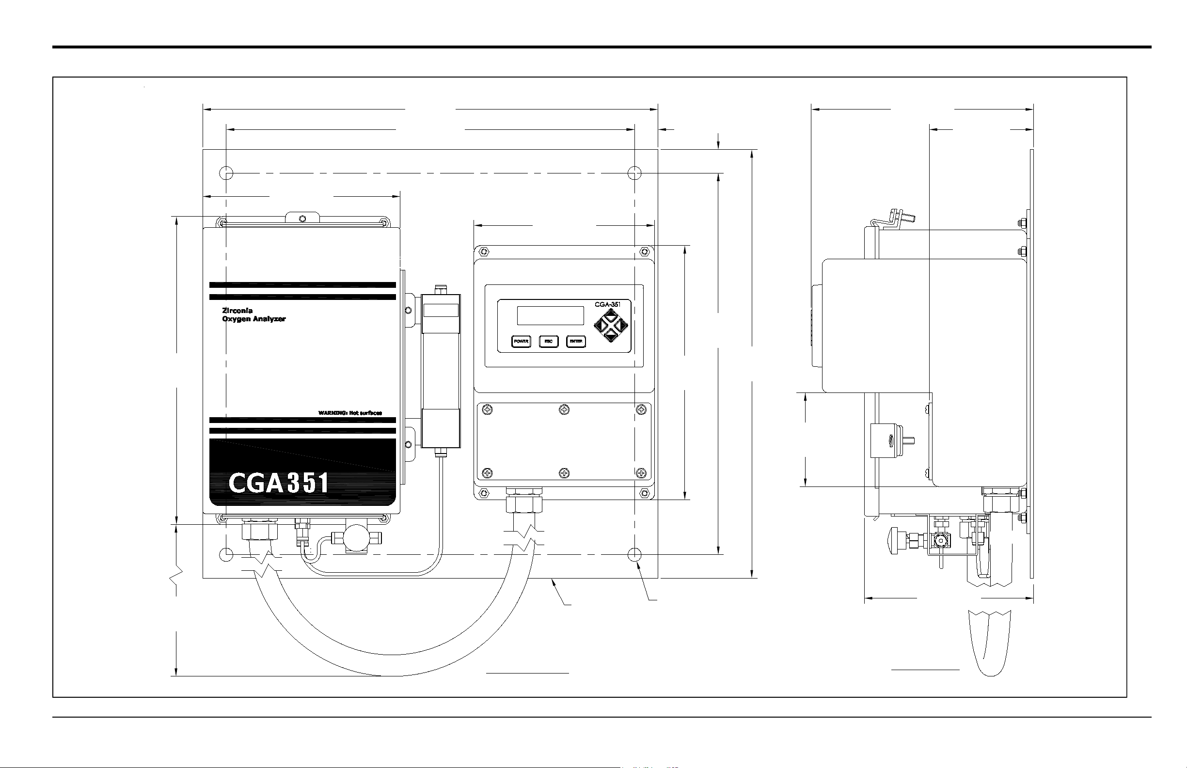
The standard CGA 351 analyzer, as shown in Figure 1 below , is supplied in a pair of stainless steel enclosures mounted
side-by-side on a metal plate with a 40” flexible conduit connecting the two. This compact, wall-mounted system
includes the following components:
• A sensor enclosure, which contains the oxygen sensor, sensor furnace, thermocouple, inlet port with needle
valve, outlet port with flowmeter, and interconnecting cable(s), and
• An electronics enclosure, which contains the temperature control circuitry, output signal processing circuitry,
digital display, user interface, and wiring terminal strips.
The CGA 351 analyzer is also available in optional enclosures (see Appendix C for more information).
Figure 1: Standard CGA 351 Analyzer
Chapter 1. General Information
2 CGA 351 User’s Manual
1.2 The Sensor Enclosure
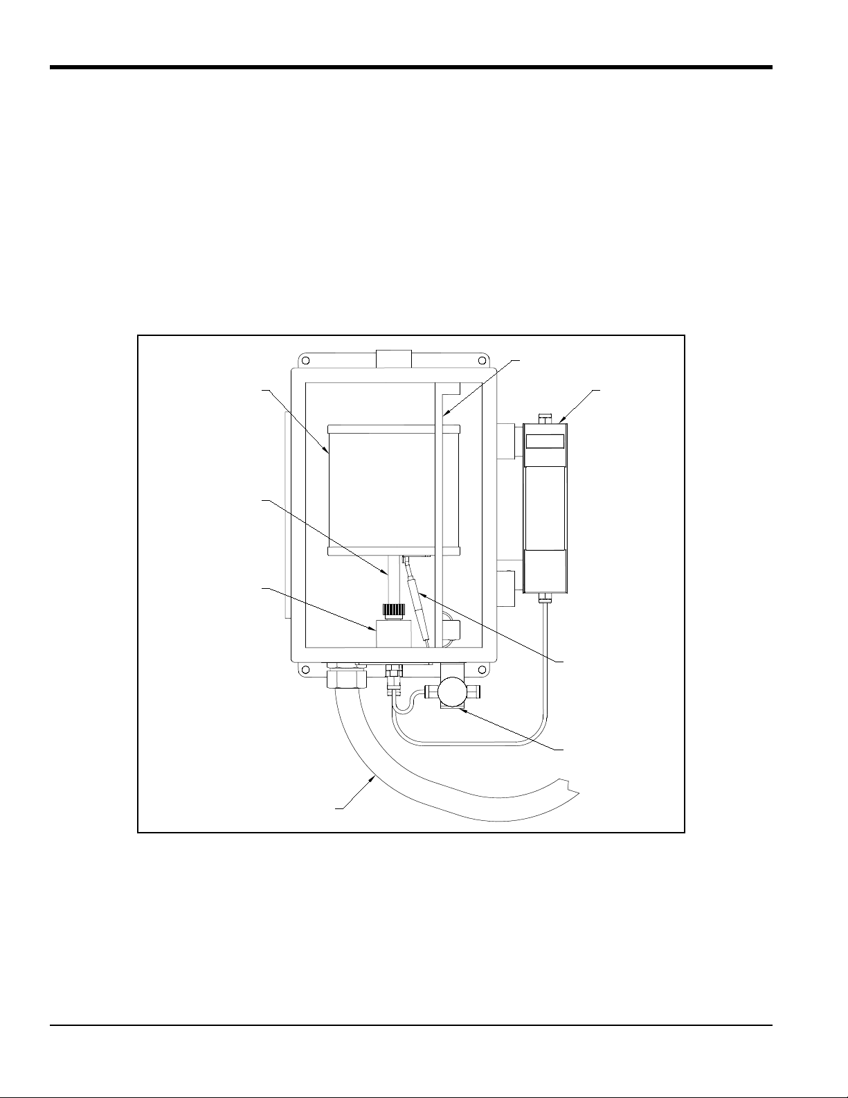
The sensor enclosure, which is shown in Figure 4 below, houses the sample measurement components. The functions
of these components are as follows:
• A zirconium oxide (zirconia) oxygen sensor converts the oxygen concentration of the sample gas into a mV
output signal.
• A sensor furnace heats the oxygen sensor and the sample gas to the optimum temperature of 700°C.
• A thermocouple precisely regulates the temperature of the oxygen sensor and the sample gas.
• An inlet needle valve and an outlet flowmeter adjust the sample gas flow to 400 ± 40 cc/min.
Figure 2: Sensor Enclosure
Furnace Bracket
Flowmeter
Thermocouple
Needle Valve
Sensor Furnace
Oxygen Sensor
Manifold
Electrical Conduit
CGA 351 User’s Manual 3
Chapter 1. General Information
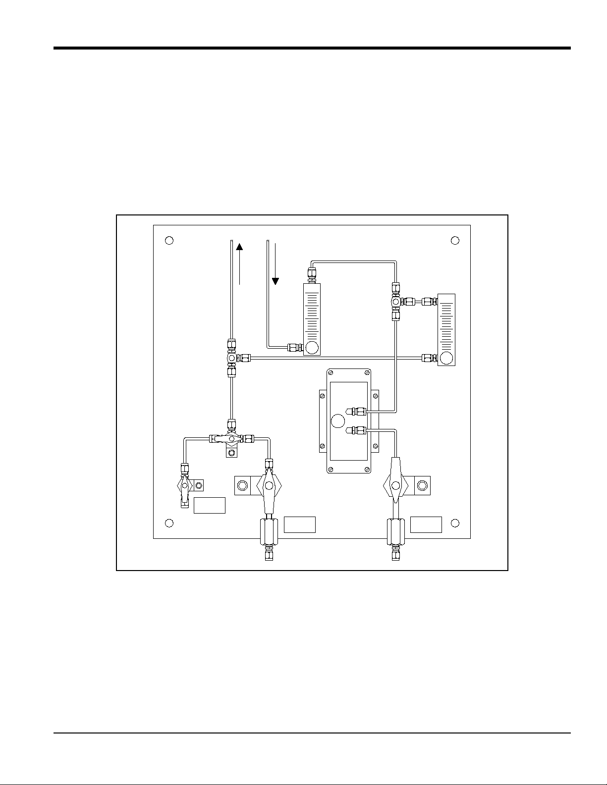
1.3 The Sample System
In addition to the components supplied with the CGA 351, an external sample system may be required to ensure that
the analyzer is fed a properly conditioned sample or calibration gas stream. In particular, the gas must be clean and dry,
and it must be delivered to the analyzer at atmospheric pressure.
Note: A suitable sample system, which will be supplied completely assembled on its own mounting plate, may be
ordered directly from GE. Commonly used sample system components include filters, pressure regulators,
pressur e gauges, by-pass loops, and sample pumps. It is recommended that stainless steel construction be used
for all wetted parts of the sample system. A typical sample system is shown in Figure 3 below.
Figure 3: Typical Sample System
SAMPLE
INLET
SAMPLE
OUTLET
INLET
CAL-GAS
INPUTOUTPUT
To: CGA 351 Inlet
From: CGA 351 Outlet

Chapter 1. General Information
4 CGA 351 User’s Manual
1.4 Principles of Operation
A gas sample is drawn into the inlet port of the analyzer by gas diffusion and a forced flow determined by the external
sample system. The sample gas then flows through a ceramic inlet tube and into the annular space between the inlet
tube and the inside of the zirconium oxide oxygen sensor. The flowmeter on the outlet port and the needle valv e on the
inlet port are used to adjust the sample flow rate to 400 ± 40 cc/min.
In the annular sample space, the gas is heated to the same 700°C at which the zirconium oxide oxygen sensor is
maintained. A mV signal is generated. This signal is proportional to the logarithm of the ratio of the oxygen
concentration in the sample gas to the oxygen concentration in a reference gas contacting the outer electrode. In the
display electronics, the logarithmic signal can be read directly in unlinearized form, or it can be converted to a
0/4–20 mA, 0–2 V, or Namur linearized signal before display.
Note: A temperature above 650°C is required for proper operation of the oxygen sensor. Also, ambient air is the
usual reference gas on the outside of the zirconium oxide sensor.
The sensor furnace also generates the convective flow that circulates the sample gas through the sample path. Pushed
from behind by the hot gases still in the furnace, the hot sample gas in the sensor furnace rises out of the furnace and
cools. The cooled sample gases then pass through the outlet port, where they are carried away by the main gas flow.
A platinum coating on the end of the ceramic tube and the zirconium oxide oxygen sensor ensures that all
oxidation/reduction reactions in the sample gas reach equilibrium. It is therefore possible to measure such parameters
as excess oxygen in air/fuel mixtures and equilibrium oxygen in reducing atmospheres such as hydrogen.
CGA 351 User’s Manual 5
Chapter 1. General Information
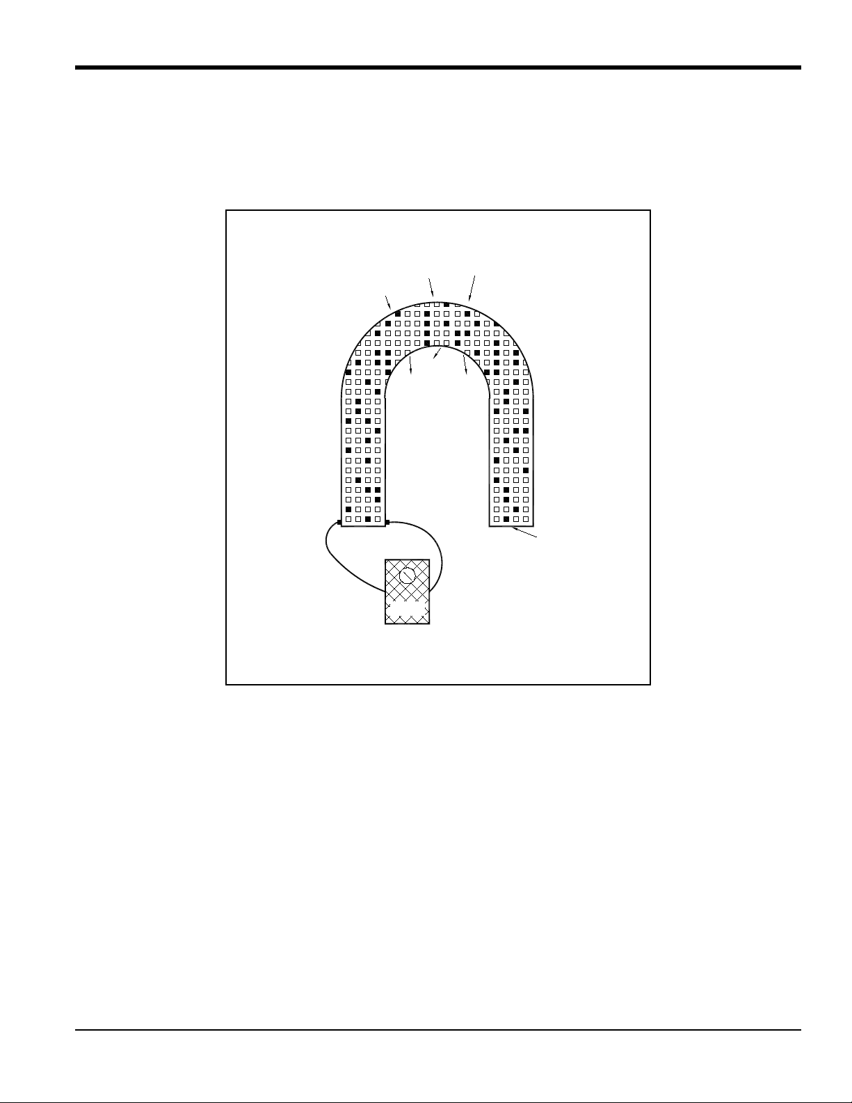
1.5 The Zirconium Oxide Oxygen Sensor
The inside and outside of the zirconium oxide oxygen sensor are coat ed wit h porou s plat inum, forming two electrodes.
The sample gas flows past the inside of the sensor, while atmospheric air circulates freely on the outside of the sensor.
This atmospheric air is used as the reference gas for making oxygen measurements (see Figure 4 below).
Figure 4: Oxygen Migration in the Zirconium Oxide Sensor
At the operating temperature of the oxygen sensor, the atmospheric reference oxygen is electrochemically reduced at
the outer electrode, and the resulting oxygen ions seek to equalize with the lower oxygen concentration on the sample
side of the cell by migrating through the porous ceramic toward the inner electrode. At the inner electrode they give up
electrons to become oxygen molecules again, and are swept away by the sample flow.
The lower the concentration of oxygen in the sample gas, the greater the rate of ion migration through the ceramic, and
the higher the cell voltage due to electron exchange at the electrodes. The cell voltage rises logarithmically as the
amount of oxygen in the sample gas falls, allowing the accurate measurement of very low levels of excess oxygen.
Volts
O
2
2
O
O
2
O
2
2
O
O
2
Sample O
Inside Cell
Oxygen ions migrate through the zirconium oxide
along the concentration gradient.
From Outside
Electrode
From Inside
Electrode
Zirconium Oxide Ceramic
with Lattice Imperfections
Atmospheric O
Outside Cell
When O concentration in sample gas falls, the cell voltage rises
with increased oxygen migration through the zirconium oxide.
2
2
2

Chapter 1. General Information
6 CGA 351 User’s Manual
1.6 The Heater Control Circuit
The oxygen sensor temperature in the CGA 351 is maintained by a heater, which is part of a complex temperature
control loop. This circuit constantly monitors the temperature input from an RTD, compares it to the set point
temperature, and turns the heater ON or OFF accordingly. The specific type of control circuit, a Proportional Integral
Derivative (PID) loop, is used because of the adjustable parameters involved:
• Proportional Band: Because the system cannot respond instantaneously to temperature changes, the actual
temperature of the oxygen sensor oscillates about the set point. In general, increasing the proportional band
reduces the magnitude of these temperature oscillations.
• Integral Action: A consequence of increasing the proportional band is the introduction of an offset between
the set point and the control point. The integral portion of the control loop acts to move the control point back
toward the set point within a specified period of time. Decreasing this integration time reduces the offset more
quickly.
Note: A third parameter, Derivative Action, is not used with the CGA 351.
The heater control circuit is configured at the factory for optimum performance. Because of the strong interaction
between the parameters involved, properly setting up the PID loop is a very complex matter. As a result, randomly
changing the P or I parameters can seriously degrade the performance of the CGA 351.
IMPORTANT: Always contact GE before attempting to change the default P or I values. The submenu for performing
these changes is password protected to prevent accidental changes.

CGA 351 User’s Manual 7
Chapter 2. Installation
Chapter 2. Installation
2.1 Introduction
This chapter provides a general description of the standard CGA 351 and gives directions on how to install and wire the
analyzer for proper operation.
Note: For information regarding component locations and/or wiring connections in an optional enclosure, see
Appendix C.
IMPORTANT: For compliance with the European Union’s Low Voltage Directive (2006/95/EC), the CGA 351 requires
an external power disconnect device such as a switch or circuit breaker. The disconnect device must be
marked as such, clearly visible, directly accessible, and located within 1.8 m (6 ft) of the unit.
WARNING! Power up the CGA 351 as quickly as possible after introduction of the sample gas. If the analyzer
is left installed without power, the unit’s components become susceptible to acid condensation
that will cause corrosion.
Be sure to observe all installation limits and precautions described in this chapter. Pay particular attention to the
ambient temperature range of –25 to +50°C (–13 to +122°F) specified for the instrument.
WARNING! To ensure safe operation of the CGA 351, the unit must be installed and operated as described in
this manual. Also, be sure to follow all applicable local safety codes and regulations for
installing electrical equipment. In addition, all procedures should be performed by trained
service personnel.
2.2 Choosing an Installation Site
All environmental and installation factors should have been discussed with a GE application engineer or field sales
person at the time the CGA 351 was ordered. Thus, the equipment should be suited to the application and the planned
installation site. Before installing the unit, however , read the following guidelines to verify that the best installation site
has been chosen for optimum instrument accuracy and reliability. Make sure that:
• The CGA 351 enclosures are suitable for the environmental conditions at the installation site.
• The analyzer system will be installed in a location with little or no vibration.
• The ambient temperature at the installation site is between –25° and 50°C (–13° and 122 °F ) .
• There are no restrictions in the discharge line (i.e. flow control valves downstream of the meter).
• The CGA 351 system is installed in a location that provides ready access for programming, testing, and
servicing the unit.
• The cables will be protected from excessive physical strain (bending, pulling, twisting, etc.). Do not subject the
cables to temperatures above 65°C (149°F) or below –50°C (–58°F).
• The line voltage used at the planned installation site corresponds to the factory preset line voltage rating for the
meter.

Chapter 2. Installation
8 CGA 351 User’s Manual
2.3 Mounting the CGA 351
This section explains how to mount the analyzer components at the installation site and how to connect the sample
system to the analyzer.
Note: If more than one analyzer system is being installed, be aware that each system is a matched set (i.e., each
sensor enclosure must
be matched to a specific electronics enclosure). Refer to the identification tags on the
enclosures to match the systems correctly.
IMPORTANT: For compliance with the European Union’s Low Voltage Directive (2006/95 /EC), th e CGA 351 requires
an external power disconnect device such as a switch or circuit breaker. The disconnect device must be
marked as such, clearly visible, directly accessible, and located within 1.8 m (6 ft) of the unit.
IMPORTANT: This symbol indicates Caution - risk of electric shock:
Refer to Figure 5 on page 13, and complete the following steps to mount the CGA 351:
1. Select a flat surface on a vertical wall or instrument panel with sufficient space to hold the mounting plate with
both of the CGA 351 enclosures.
Note: Mount the system in an upright position, so that the sample inlet and outlet fittings are on the bottom of the
sensor enclosure.
2. Using the mounting dimensions shown in Figure 5 on page 13, locate and prepare four (4) mounting holes or two
(2) horizontal mounting rails on the vertical surface.
3. Secure the system to the mounting surface with four (4) sets of mounting hardware. Be sure that the enclosures are
in a vertical position, with the inlet/outlet connectors on the bottom.
4. The flowmeter, which is fastened to the right side of the sensor enclosure, is connected to the discharge port on the
bottom of the unit with a length of 6mm stainless steel tubing. Make sure that the factory-installed Swagelok
fittings are secure.
5. A flow control valve is attached to the inlet port on the bottom of the sensor enclosure with 6mm stainless steel
tubing and Swagelok fittings. Point the valve in the proper direction to receive the inlet piping from the sample
system, and securely tighten the fittings.
2.4 Connecting the Sample System
The sample system should be located so that it is able to deliver a sample at a flow rate of 400 ±40 cc/min. For best
results, mount the sample system as close as possible to the CGA 351. An ideal location would be on the same panel,
just below the analyzer. If there are questions, consult with an applications engineer at the factory.
See Figure 5 on page 13, and complete the following steps to connect the sample system to the analyzer:
1. Using 6mm stainless steel tubing (or ¼” stainless steel tubing with adaptors), connect the gas source from the
sample system to the Swagelok fitting on the flow control valve at the inlet port on the analyzer.
2. Using 6 mm stainless steel tubing (or ¼” stainless steel tubing with adaptors), connect the Swagelok outlet fitting
at the top of the flowmeter on the analyzer to the gas discharge connection on the sample system.
Note: If desired, a suitable sample system may be ordered directly from the factory. The sample system would be
supplied fully assembled on a flat plate with four (4) mounting holes.

CGA 351 User’s Manual 9
Chapter 2. Installation
2.5 Wiring the Analyzer
The system components which are housed in the sensor enclosure have already been wired at the factory. These
include:
• Oxygen sensor (TB2)
• Thermocouple (TB2)
• Sensor furnace (TB2)
To completely wire the CGA 351 zirconium oxide oxygen analyzer, the following items must be connected:
• Serial port (TB1)
• Analog output (TB1)
• Alarm relays (TB1)
• Line power (TB3)
Refer to the wiring diagram shown in Figure 6 on page 14, while completing the instructions in this section.
WARNING! In order to meet CE Mark requirements, all cables must installed as described in Appendix B, CE
Mark Compliance.
IMPORTANT: For compliance with the European Union’s Low Voltage Directive (2006/95/EC), the CGA 351 requires
an external power disconnect device such as a switch or circuit breaker. The disconnect device must be
marked as such, clearly visible, directly accessible, and located within 1.8 m (6 ft) of the unit.
WARNING! To ensure safe operation of the CGA 351, the unit must be installed and operated as described in
this manual. Also, be sure to follow all applicable local safety codes and regulations for
installing electrical equipment. In addition, all procedures should be performed by trained
service personnel.
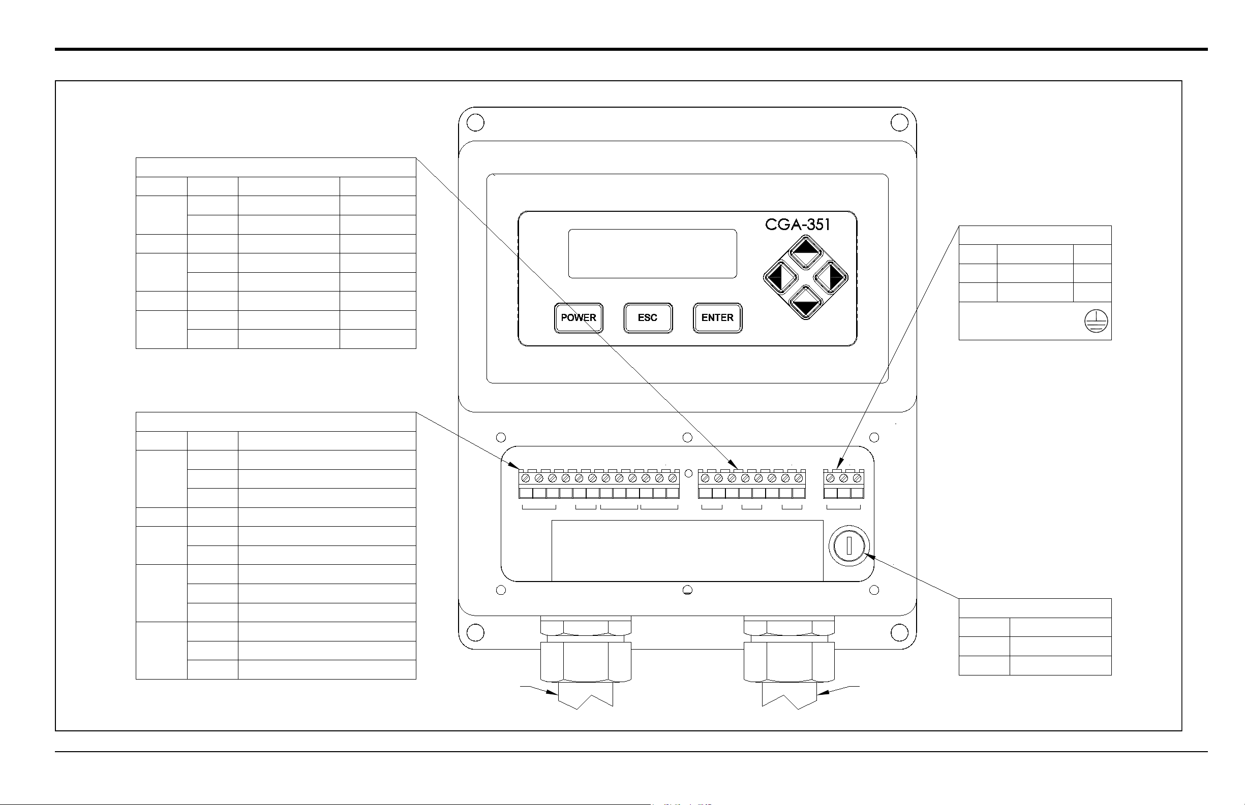
To access the terminal printed circuit board, remove the cover below the digital display panel, which is fastened with
six (6) Phillips head screws. The PC Board has terminal blocks TB1 (12 connections), TB2 (8 connections), and TB3
(3 connections) mounted on it. Proceed to the appropriate sub-section to wire each of these terminal blocks.

Chapter 2. Installation
10 CGA 351 User’s Manual
2.5.1 Wiring the Outputs (TB1)
Terminal block TB1 contains connections for the CGA 351’s output signals. Specifically, the following signals are
available at this terminal block:
• Serial port
• 0/4–20 mA, 0–2 V, or Namur analog output
• Alarm relays
To wire any or all of these output signals, complete the following steps:
1. Attach a cable or conduit with the appropriate number of conductors to an entry port on the bottom of the
electronics enclosure.
2. To connect a serial port from a personal computer, use the COMM pins on terminal block TB1 as follows:
a. Connect the transmit wire to pin
1.
b. Connect the receive wire to pin
2.
c. Connect the ground/return wire to pin
C.
3. To connect an analog output device, use the 4-20mA pins on terminal block TB1 as follows:
a. Connect the input wire to the external device to pin
+.
b. Connect the output wire from the external device to pin
–.
4. To connect alarm device(s), use the ALARM 1 and/or ALARM 2 pins on terminal block TB1 as follows:
a. Connect the input wire to the alarm-1 device to pin
NO.
b. Connect the output wire from the alarm-1 device to pin
C.
c. If desired, repeat sub-steps a and b to connect alarm-2.
5. Connect any shields to pin
G.
Proceed to the next section to continue wiring the CGA 351.

CGA 351 User’s Manual 11
Chapter 2. Installation
2.5.2 Wiring the Inputs (TB2)
Terminal block TB2 contains connections for the CGA 351’s sample measurement signals. Specifically, the following
signals are routed to this terminal block:
• Zirconium oxide oxygen sensor
• Thermocouple
• Sensor furnace
All of the connections on terminal block TB2 have already been wired at the factory. In the event that one or more of
these wires must be reconnected, complete the following steps:
1. Locate the leads from the zirconium oxide oxygen sensor. Connect these leads to terminal block TB2 as follows:
a. Connect the positive sensor wire (white - #1) to pin
+.
b. Connect the negative sensor wire (white - #2) to pin
–.
2. Locate the leads from the thermocouple. Connect these leads to terminal block TB2 as follows:
a. Connect the positive thermocouple wire (yellow - no number) to pin
+.
b. Connect the negative thermocouple wire (red - no number) to pin
–.
Note: The two thermocouple wires (red and yellow) are bound together in a brown sheath.
3. Locate the leads from the sensor furnace. Connect these leads to terminal block TB2 as follows:
a. Connect one furnace wire (white - #5) to pin
1.
b. Connect the other furnace wire (white - #6) to pin
2.
Note: The polarity of the sensor furnace leads is not important.
4. Connect the ground wire (white - #G) and any shields to either of the pins labeled
G.
This completes the wiring of terminal block TB2. Proceed to the next section to continue wiring the CGA 351.

Chapter 2. Installation
12 CGA 351 User’s Manual
2.5.3 Wiring the Line Power (TB3)
Terminal block TB3 contains connections for the line power to the CGA 351. To wire the line power, complete the
following steps:
WARNING! Before proceeding with the section, verify that the line power has been turned off at the external
disconnect device.
1. Attach a cable or conduit with the three line power conductors to an entry port on the bottom of the electronics
enclosure.
CAUTION! Be sure that the input voltage to the CGA 351 complies with the value specified at the time of
purchase. If the voltage is incorrect, contact the factory immediately.
2. Connect the line power leads to terminal block TB3 as follows:
a. Connect the line power lead (black) to pin
L.
b. Connect the neutral power lead (white) to pin
N.
c. Connect the ground power lead (green) to the protective earth ground post, identified by .
This completes the wiring of the CGA 351 analyzer. Proceed to Chapter 3, Operation, for instructions on using the
analyzer.
Chapter 1. Installation
CGA 351 User’s Manual 13
16
(406)
11 1/2
(292)
9 1/2
(241)
3 1/2
(89)
6 3/4 (171)
7 3/8 (187)
6 3/8 (162)
SIDE VIEW
FRONT VIEW
16
(406)
14 1/4
(362)
7/8 (22)
7/8 (22)
8 1/4 (208)
3 7/8 (98)15 1/4 (387)
17 (432)
Ø1/2 (Ø12.7) 4pl
Mounting Hole
Mounting
Note: Dimensions are in inches (millimeters).
Plate
Figure 5: CGA 351 Mounting Dimensions
Chapter 1. Installation
CGA 351 User’s Manual 14
FUSE
TB3
TB2
TB1
COMM 4-20mA ALARM 1 ALARM 2 O2 TC HEATER 90-265 VAC
Group
COMM
4-20mA
ALARM 1
ALARM 2
Pin #
1
2
C
G
+
-
NO
C
NC
NO
C
NC
ALL
Description
RS232 Transmit (TX)
RS232 Receive (RX)
RS232 Return (RTN)
Any Shield or Ground
Analog Output (SIG+)
Analog Output (SIG-)
Normally Open (Standard Mode)
Common
Normally Closed (Failsafe Mode)
Normally Open (Standard Mode)
Common
Normally Closed (Failsafe Mode)
TB1 - OUTPUTS
HEATER
TC
Thermocouple (-)
Furnace (+)
Any Gnd/Shield
1
2
Furnace (-)
G
-
G
+
Any Gnd/Sh
ield
Thermocouple (+)
O2
Group
Description
TB2 - INPUTS
-
+
Pin #
Sensor (-)
Sensor (+)
ALL
ALL
6 (White)
5 (White)
N.A.
G (White)
N.A. (Red)
N.A.(Yellow)
2 (White)
1 (White)
Wire # (Color)
TB3 - POWER*
N
L
Pin #
5 x 20 mm
Size:
4 A, 250 V
FUSE
Type:
Rating:
TD (Time-Delay)
*90-265 VAC, 50/60 Hz, 900 W
NOTE: For proper operation,
the unit must be powered by
the voltage specified at the
time of purchase.
Description
Line
Neutral
Color
Black
White
Outputs/PowerInputs Conduit
CCG
+
C21
-
21G
-
+
G
-
+
LNGNC NCNO NO
DS1
Conduit
Ground unit to protective
earth post provided.
Figure 6: CGA 351 Wiring Connections

CGA 351 User’s Manual 15
Chapter 3. Operation
Chapter 3. Operation
3.1 Introduction
The CGA 351 is an easily-operated monitoring d evice. Before applying power , make sure the system has been installed
in accordance with the instructions given in Chapter 2, Installation.
Note: For information regarding component locations and wiring connections in an optional enclosure, see
Appendix C.
Allow the unit to warm up for at least thirty minutes prior to use. Check to see if it is hot. Observe all normal safety
precautions. Specifically, do not exceed the maximum pressure and temperature ratings of the zirconium oxide oxygen
sensor and the sample system.
This chapter includes discussions of the following topics:
• preventing common problems
• powering up the system
• configuring the digital display
• taking measurements
WARNING!
To ensure safe operation of the CGA 351, it must be installed and operated as described in this
manual. In addition, be sure to follow all applicable local safety codes and regulations for
installing electrical equipment.
3.2 Preventing Common Problems
Use the CGA 351 to accurately measure low oxygen levels. To avoid problems, observe the following:
• Check the calibration of the analyzer once or twice a week for the first month of operation and once every
2–3 months thereafter (see Chapter 4, Setup and Calibration, for instructions).
• Never use thread sealant on any connection in the sample gas flow path. Thread sealant gives off combustible
vapors that can cause reading errors.
• Do not handle the oxygen sensor with bare hands. Although some scratches on the platinum coating can be
tolerated, rubbing the coating should be avoided.
• Clean the oxygen sensor only by rinsing it with clean water , after the sensor has cooled. Scrubbing the oxygen
sensor or washing a hot sensor in cold water can damage or destroy it.
• Do not disturb the special sealant on the oxygen sensor nut and the inlet fittings. Any leakage in these areas
will cause inaccurate readings when measuring low oxygen levels.

Chapter 3. Operation
16 CGA 351 User’s Manual
3.3 Powering Up the System
Before applying power, check the wiring connections and close both enclosures. Energize the external disconnect
device to power up the CGA 351. For reliable readings, allow approximately two hours for the analyzer to reach
temperature equilibrium before taking measurements.
WARNING!
To prevent corrosion, the analyzer must be powered up immediately after introduction of the
sample gas. If the analyzer is left installed without power, the unit’s components become
susceptible to acid condensation that will cause corrosion.
If the power must be removed for more than thirty minutes, purge the analyzer through the
inlet port with a continuous flow of instrument air at a rate of 400 ± 40 cc/min.
IMPORTANT: For compliance with the European Union’s Low Voltage Directive (2006/95 /EC), th e CGA 351 requires
an external power disconnect device such as a switch or circuit breaker. The disconnect device must be
marked as such, clearly visible, directly accessible, and located within 1.8 m (6 ft) of the unit.
3.4 User Program Security
The CGA 351 has been equipped with a User Program (see the menu map in Figure 8 on page 25) that permits the
setup and calibration of the instrument for optimum performance in any specific application. However, to prevent
accidental changes to critical system parameters, four levels of security are imposed on the various submenus within
the User Program. These are:
• Unlocked - access to these submenus is gained simply by pressing the [ESC] key. No password is required.
• Basic (locked) - access to these submenus is gained by pressing the [ESC], [ENT], and [ESC] keys in sequence.
Then, a password must be entered. (The default password is 2719.)
• General (locked) - access to these submenus is gained by pressing the [ESC], [ENT], and [ESC] keys in
sequence. Then, a password must be entered.
• Advanced (locked) - access to these submenus is gained by pressing the [ESC], [ENT], and [ESC] keys in
sequence. Then, a password must be entered.
Note: The passwords required for the three locked categories mentioned above are all different.
CGA 351 User’s Manual 17
Chapter 3. Operation
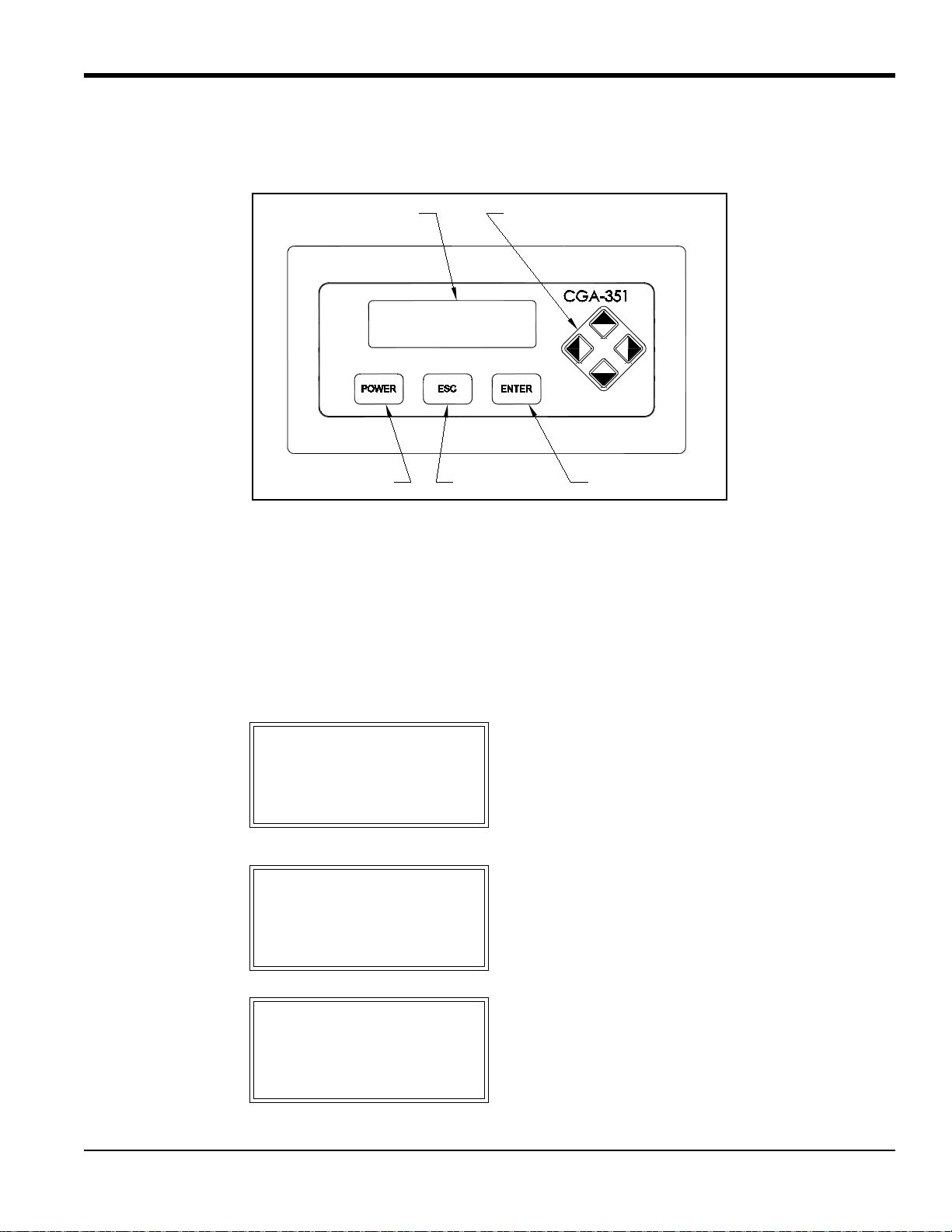
3.5 Configuring the Digital Display
The digital display panel at the top of the electronics enclosure includes the components shown in Figure 7 below.
Figure 7: Digital Display Panel
A typical display will be configured to the customer’s needs at the factory. If changes are required, follow the
instructions in this section to complete the initial configuration of the digital display. As an aid in performing this task,
refer to the menu map in Figure 8 on page 25.
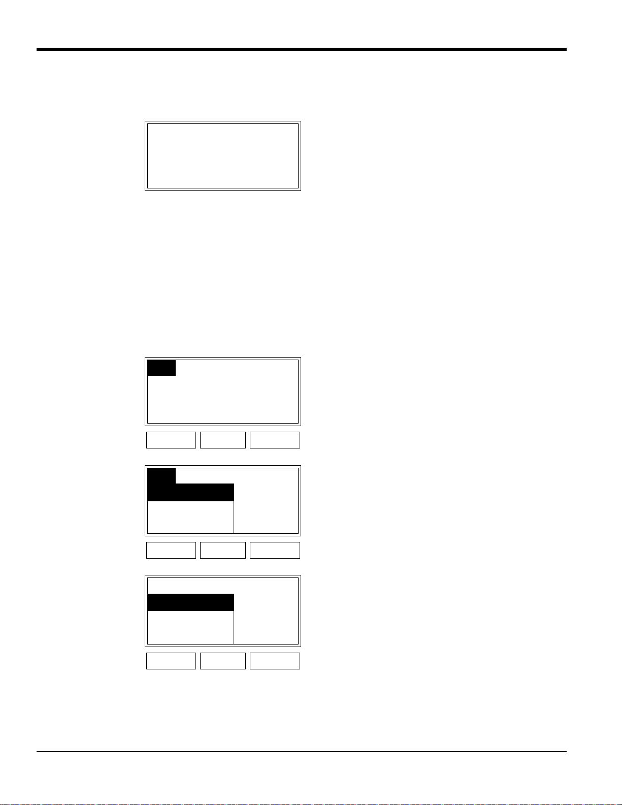
3.5.1 Initial Screen Displays
Immediately upon power up, the digital display shows the following sequence of informational screens, as the meter
performs its internal systems checks:
BSeries Loader v1.05 This is a typical example of
the first initialization screen.
Boot is Flash.
Program CRC valid.
Booting from Flash
Scanning Hardware This is a typical example of
the second initialization
screen.
Found Image Slot 1
Downloading Slot 1
Scanning Hardware This is a typical example of
the final initialization screen.
Initializing Machine
Initializing UI
Display Window
ESC Button ENTER Button
Cursor Control Keypad
POWER Button
Chapter 3. Operation
18 CGA 351 User’s Manual
3.5.1 Initial Screen Displays (cont.)
If the meter passes all of its internal system checks, the following screen appears:
Note: The padlock icon at the upper right hand corner of the above display indicates that the User Program is locked
with password protection.
Before any data can be displayed, the meter must be configured for the desired display parameter(s). Enter the User
Program by pressing the
[ESC] key and proceed as follows.
IMPORTANT: In some applications, portions of the User Program may be locked to prevent end user access. If this is
the case, entrance to these submenus requires a special key sequence and a password (see page 16).
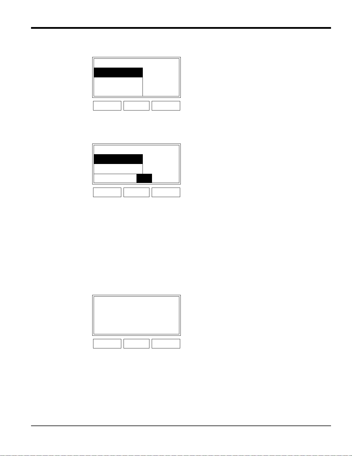
3.5.2 Configuration Options
Note: The [CJC Temp] and [Duty Cycle] options are also available in the above list box.
1 Oxygen
This is a typical example of an
initial screen.
Heater Warming
Cfg
Cal Opt Disp Upon entering the User
Program, the
[Cfg] option is
already selected. Simply press
[ENTER]. (Notice that the
[Disp] option is grayed out at
this time.
POWER ESC ENTER
Cfg
Cal Opt Disp To proceed with the [1: Cfg]
option, press
[ENTER]. To
abort the operation, press
[ESC].
1: Cfg
POWER ESC ENTER
From 1: Cfg A list of the available display
inputs is shown. Use the [
]
and [
] keys to select the
desired input and press
[ENTER]. Oxygen has been
selected as an example.
Oxygen
Temperature
Sensor
POWER ESC ENTER
CGA 351 User’s Manual 19
Chapter 3. Operation
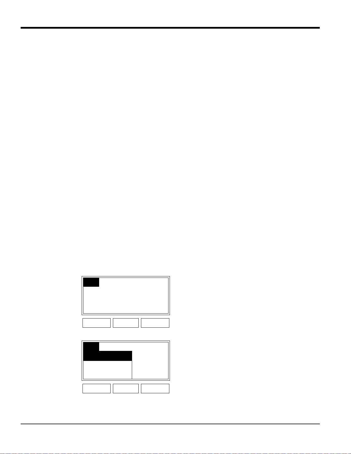
3.5.2 Configuration Options (cont.)
If either of the Temperature inputs is selected for display, °C and °F are available as the unit types. For the Sensor and
Duty Cycle inputs, mV and pcnt, respectively, are the only available unit types.
Note: The
[0:Analog Output], [2:Alarm-1], [2:Alarm-2], [2:Alarm-3] and [2:Alarm-4] options are also available in the
above list box.
To select the desired output(s) from the previous list box, complete the following steps:
1. Use the [
] and [] keys to highlight a specific output. For this example, make sure that [0: Display] is selected as
one of the outputs.
2. Use the [
] and [] keys to select “Add” or “Remove” and press the [ENTER] key to change the status of the
selected output. An output is selected if an asterisk (*) appears to its left.
3. When all of the desired outputs have been selected, use the [
] and [] keys to select “OK” and press [ENTER].
Notice that the newly-configured display shows the slot number and the input parameter on the top line, and the
current live value along with the unit type are displayed in the center of the screen.
Note: See Chapter 4, Setup and Calibration, for instructions on how to adjust the display contrast.
From 1: Cfg Oxygen A list of the available unit
types is shown. Use the [
]
and [
] keys to select the
desired units (parts per million
or percent) and press
[ENTER].
ppm
pcnt
AF
POWER ESC ENTER
From 1: Cfg Ox..pcnt A list of the available output
devices is shown. Follow the
instructions below to select the
desired outputs.
*0: Display
*0: Fault Alarm
Add Remove
OK
Cancel
POWER ESC ENTER
1 Oxygen Press [ESC] four times to
return the display to the actual
set configuration.
2.71 ppm
POWER ESC ENTER
Chapter 3. Operation
20 CGA 351 User’s Manual
3.5.3 Using the Auto Range Feature
The Auto Range feature includes three unit types:
• ARng (Auto Range %): the ratio of the current oxygen reading to the currently active Auto Range, expressed
as a percentage
• AR-A (Auto Range Alarm A): automatically set to a value of 0 or 1
• AR-B (Auto Range Alarm B): automatically set to a value of 0 or 1
As an example of how these units work with the default values listed in T a ble 3 on page 44, consider a situation where
the current oxygen reading is 7.5%. The Auto Range feature would select the current active range as Range 3 in the
table. Then,
(1)
This means that the current oxygen reading represents 75% of the currently active Auto Range. In addition to the ARng
value calculated above, AR-A = 0 and AR-B = 1, as shown in the table.
After programming the Auto Ranges, the CGA 351 must be configured to properly h andle the Auto Range output. To
accomplish this, the following outputs must be reprogrammed:
• Alarm A and Alarm B
• 4-20 mA analog output
3.5.4 Configuring the Alarms
The first step in setting up the alarms is to assign the correct unit types. T o accomplish this, proceed as follows from the
Main Menu:
Cfg
Cal Opt Disp Upon entering the User
Program, the
[Cfg] option is
already selected. Simply press
[ENTER].
POWER ESC ENTER
Cfg
Cal Opt Disp To proceed with the [1: Cfg]
option, press
[ENTER].
1: Cfg
POWER ESC ENTER
ARng
%O2()AR Zero()–
AR Span()AR Zero()–
----------------------------------------------------------
100× 75%==
Loading...