

Page 1
PanaFlow™ Z1G/Z2G
User’s Manual
Flow
bhge.com
910-321 Rev. A
Jun 2018
Page 2

Page 3

PanaFlow™ Z1G/Z2G
Gas Ultrasonic Volumetric Flow Meter
User’s Manual
910-321 Rev. A
Jun 2018
bhge.com
© 2017 Baker Hughes, a GE company – All rights reserved.
Baker Hughes reserves the right to make changes in specifications and features shown herein, or discontinue the product
described at any time without notice or obligation. Contact your BHGE representative for the most current information. The
Baker Hughes logo is a trade mark of Baker Hughes, a GE company. The GE Monogram is a trademark of the General Electric
Company.
Page 4

[no content intended for this page]
Page 5

Contents
Product Registration . . . . . . . . . . . . . . . . . . . . . . . . . . . . . . . . . . . . . . . . . . . . . . . . . . . . . . . . . . . . . . . . . . . . . . . . . . . . . . . . . . . . . . . . . . . . v
Services . . . . . . . . . . . . . . . . . . . . . . . . . . . . . . . . . . . . . . . . . . . . . . . . . . . . . . . . . . . . . . . . . . . . . . . . . . . . . . . . . . . . . . . . . . . . . . . . . . . . . . . . v
Terms and Conditions. . . . . . . . . . . . . . . . . . . . . . . . . . . . . . . . . . . . . . . . . . . . . . . . . . . . . . . . . . . . . . . . . . . . . . . . . . . . . . . . . . . . . . . . . . . v
Typographical Conventions . . . . . . . . . . . . . . . . . . . . . . . . . . . . . . . . . . . . . . . . . . . . . . . . . . . . . . . . . . . . . . . . . . . . . . . . . . . . . . . . . . . . . v
Safety Issues . . . . . . . . . . . . . . . . . . . . . . . . . . . . . . . . . . . . . . . . . . . . . . . . . . . . . . . . . . . . . . . . . . . . . . . . . . . . . . . . . . . . . . . . . . . . . . . . . . . v
Auxiliary Equipment . . . . . . . . . . . . . . . . . . . . . . . . . . . . . . . . . . . . . . . . . . . . . . . . . . . . . . . . . . . . . . . . . . . . . . . . . . . . . . . . . . . . . . . . . . . .vi
Environmental Compliance . . . . . . . . . . . . . . . . . . . . . . . . . . . . . . . . . . . . . . . . . . . . . . . . . . . . . . . . . . . . . . . . . . . . . . . . . . . . . . . . . . . . vii
Chapter 1. General Information
1.1 Theory of Operation . . . . . . . . . . . . . . . . . . . . . . . . . . . . . . . . . . . . . . . . . . . . . . . . . . . . . . . . . . . . . . . . . . . . . . . . . . . . . . . . . . . . . . . 1
1.1.1 Transit-Time Method. . . . . . . . . . . . . . . . . . . . . . . . . . . . . . . . . . . . . . . . . . . . . . . . . . . . . . . . . . . . . . . . . . . . . . . . . . . . . . 1
1.1.2 Transducers . . . . . . . . . . . . . . . . . . . . . . . . . . . . . . . . . . . . . . . . . . . . . . . . . . . . . . . . . . . . . . . . . . . . . . . . . . . . . . . . . . . . . . 1
1.2 Multi-Path Design . . . . . . . . . . . . . . . . . . . . . . . . . . . . . . . . . . . . . . . . . . . . . . . . . . . . . . . . . . . . . . . . . . . . . . . . . . . . . . . . . . . . . . . . . 1
1.3 Flow Profile . . . . . . . . . . . . . . . . . . . . . . . . . . . . . . . . . . . . . . . . . . . . . . . . . . . . . . . . . . . . . . . . . . . . . . . . . . . . . . . . . . . . . . . . . . . . . . . 1
1.4 Unpacking. . . . . . . . . . . . . . . . . . . . . . . . . . . . . . . . . . . . . . . . . . . . . . . . . . . . . . . . . . . . . . . . . . . . . . . . . . . . . . . . . . . . . . . . . . . . . . . . . 2
1.5 Inspection. . . . . . . . . . . . . . . . . . . . . . . . . . . . . . . . . . . . . . . . . . . . . . . . . . . . . . . . . . . . . . . . . . . . . . . . . . . . . . . . . . . . . . . . . . . . . . . . . 2
1.6 Meter Components. . . . . . . . . . . . . . . . . . . . . . . . . . . . . . . . . . . . . . . . . . . . . . . . . . . . . . . . . . . . . . . . . . . . . . . . . . . . . . . . . . . . . . . . 2
1.7 Tag Plates . . . . . . . . . . . . . . . . . . . . . . . . . . . . . . . . . . . . . . . . . . . . . . . . . . . . . . . . . . . . . . . . . . . . . . . . . . . . . . . . . . . . . . . . . . . . . . . . . 4
1.7.1 Model Tag Plate. . . . . . . . . . . . . . . . . . . . . . . . . . . . . . . . . . . . . . . . . . . . . . . . . . . . . . . . . . . . . . . . . . . . . . . . . . . . . . . . . . . 4
1.7.2 Specification Tag Plate. . . . . . . . . . . . . . . . . . . . . . . . . . . . . . . . . . . . . . . . . . . . . . . . . . . . . . . . . . . . . . . . . . . . . . . . . . . . 4
1.7.3 Part String and Serial Number Tag Plate. . . . . . . . . . . . . . . . . . . . . . . . . . . . . . . . . . . . . . . . . . . . . . . . . . . . . . . . . . . 5
1.7.4 Transmitter Tag Plate . . . . . . . . . . . . . . . . . . . . . . . . . . . . . . . . . . . . . . . . . . . . . . . . . . . . . . . . . . . . . . . . . . . . . . . . . . . . . 5
Chapter 2. Installation
2.1 Introduction. . . . . . . . . . . . . . . . . . . . . . . . . . . . . . . . . . . . . . . . . . . . . . . . . . . . . . . . . . . . . . . . . . . . . . . . . . . . . . . . . . . . . . . . . . . . . . . 7
2.2 Lifting Instructions . . . . . . . . . . . . . . . . . . . . . . . . . . . . . . . . . . . . . . . . . . . . . . . . . . . . . . . . . . . . . . . . . . . . . . . . . . . . . . . . . . . . . . . . 7
2.3 Flowcell Location Guidelines . . . . . . . . . . . . . . . . . . . . . . . . . . . . . . . . . . . . . . . . . . . . . . . . . . . . . . . . . . . . . . . . . . . . . . . . . . . . . . 9
2.4 Making the Electrical Connections . . . . . . . . . . . . . . . . . . . . . . . . . . . . . . . . . . . . . . . . . . . . . . . . . . . . . . . . . . . . . . . . . . . . . . . .10
2.4.1 Wiring the Line Power . . . . . . . . . . . . . . . . . . . . . . . . . . . . . . . . . . . . . . . . . . . . . . . . . . . . . . . . . . . . . . . . . . . . . . . . . . .11
2.4.2 Wiring the Transducers . . . . . . . . . . . . . . . . . . . . . . . . . . . . . . . . . . . . . . . . . . . . . . . . . . . . . . . . . . . . . . . . . . . . . . . . . .12
2.4.3 Wiring the Standard 4-20 mA Analog Outputs. . . . . . . . . . . . . . . . . . . . . . . . . . . . . . . . . . . . . . . . . . . . . . . . . . . .12
2.4.4 Wiring the Standard RS485 Serial Port . . . . . . . . . . . . . . . . . . . . . . . . . . . . . . . . . . . . . . . . . . . . . . . . . . . . . . . . . . .13
2.4.5 Wiring the Option Cards . . . . . . . . . . . . . . . . . . . . . . . . . . . . . . . . . . . . . . . . . . . . . . . . . . . . . . . . . . . . . . . . . . . . . . . . .13
Chapter 3. Initial Setup
3.1 Introduction. . . . . . . . . . . . . . . . . . . . . . . . . . . . . . . . . . . . . . . . . . . . . . . . . . . . . . . . . . . . . . . . . . . . . . . . . . . . . . . . . . . . . . . . . . . . . .21
3.2 Programming Methods . . . . . . . . . . . . . . . . . . . . . . . . . . . . . . . . . . . . . . . . . . . . . . . . . . . . . . . . . . . . . . . . . . . . . . . . . . . . . . . . . . .21
3.3 The Magnetic Keypad. . . . . . . . . . . . . . . . . . . . . . . . . . . . . . . . . . . . . . . . . . . . . . . . . . . . . . . . . . . . . . . . . . . . . . . . . . . . . . . . . . . . .22
3.4 Initial Power On Screens. . . . . . . . . . . . . . . . . . . . . . . . . . . . . . . . . . . . . . . . . . . . . . . . . . . . . . . . . . . . . . . . . . . . . . . . . . . . . . . . . .23
3.5 Entering Data in the GLOBL Menu . . . . . . . . . . . . . . . . . . . . . . . . . . . . . . . . . . . . . . . . . . . . . . . . . . . . . . . . . . . . . . . . . . . . . . . .24
3.5.1 Entering Global System Data. . . . . . . . . . . . . . . . . . . . . . . . . . . . . . . . . . . . . . . . . . . . . . . . . . . . . . . . . . . . . . . . . . . . .24
3.5.2 Selecting Volumetric Units. . . . . . . . . . . . . . . . . . . . . . . . . . . . . . . . . . . . . . . . . . . . . . . . . . . . . . . . . . . . . . . . . . . . . . .25
3.5.3 Selecting Totalizer Units . . . . . . . . . . . . . . . . . . . . . . . . . . . . . . . . . . . . . . . . . . . . . . . . . . . . . . . . . . . . . . . . . . . . . . . . .25
PanaFlow™ Z1G/Z2G User’s Manual iii
Page 6

Contents
3.5.4 Selecting Mass Flow Units . . . . . . . . . . . . . . . . . . . . . . . . . . . . . . . . . . . . . . . . . . . . . . . . . . . . . . . . . . . . . . . . . . . . . . .26
3.6 Activating a Channel . . . . . . . . . . . . . . . . . . . . . . . . . . . . . . . . . . . . . . . . . . . . . . . . . . . . . . . . . . . . . . . . . . . . . . . . . . . . . . . . . . . . .27
3.7 Entering System Data for a Channel . . . . . . . . . . . . . . . . . . . . . . . . . . . . . . . . . . . . . . . . . . . . . . . . . . . . . . . . . . . . . . . . . . . . . .28
3.7.1 Accessing the Channelx-System Submenu . . . . . . . . . . . . . . . . . . . . . . . . . . . . . . . . . . . . . . . . . . . . . . . . . . . . . . .28
3.7.2 Selecting Volumetric Units. . . . . . . . . . . . . . . . . . . . . . . . . . . . . . . . . . . . . . . . . . . . . . . . . . . . . . . . . . . . . . . . . . . . . . .28
3.7.3 Selecting Totalizer Units . . . . . . . . . . . . . . . . . . . . . . . . . . . . . . . . . . . . . . . . . . . . . . . . . . . . . . . . . . . . . . . . . . . . . . . . .28
3.7.4 Selecting Mass Flow Units . . . . . . . . . . . . . . . . . . . . . . . . . . . . . . . . . . . . . . . . . . . . . . . . . . . . . . . . . . . . . . . . . . . . . . .29
Chapter 4. Operation
4.1 Introduction. . . . . . . . . . . . . . . . . . . . . . . . . . . . . . . . . . . . . . . . . . . . . . . . . . . . . . . . . . . . . . . . . . . . . . . . . . . . . . . . . . . . . . . . . . . . . .33
4.2 Powering Up . . . . . . . . . . . . . . . . . . . . . . . . . . . . . . . . . . . . . . . . . . . . . . . . . . . . . . . . . . . . . . . . . . . . . . . . . . . . . . . . . . . . . . . . . . . . .34
4.3 The PanaFlow Z1G/Z2G Process Gas Flowmeter LCD Display. . . . . . . . . . . . . . . . . . . . . . . . . . . . . . . . . . . . . . . . . . . . . .35
4.4 The Optional PanaView Display. . . . . . . . . . . . . . . . . . . . . . . . . . . . . . . . . . . . . . . . . . . . . . . . . . . . . . . . . . . . . . . . . . . . . . . . . . .36
4.5 Taking Measurements . . . . . . . . . . . . . . . . . . . . . . . . . . . . . . . . . . . . . . . . . . . . . . . . . . . . . . . . . . . . . . . . . . . . . . . . . . . . . . . . . . . .37
4.5.1 Programming the LCD Display . . . . . . . . . . . . . . . . . . . . . . . . . . . . . . . . . . . . . . . . . . . . . . . . . . . . . . . . . . . . . . . . . . .37
4.5.2 Programming the PanaView Display. . . . . . . . . . . . . . . . . . . . . . . . . . . . . . . . . . . . . . . . . . . . . . . . . . . . . . . . . . . . . .40
4.5.3 Pausing Measurements . . . . . . . . . . . . . . . . . . . . . . . . . . . . . . . . . . . . . . . . . . . . . . . . . . . . . . . . . . . . . . . . . . . . . . . . . .43
4.6 . . . . . . . . . . . . . . . . . . . . . . . . . . . . . . . . . . . . . . . . . . . . . . . . . . . . . . . . . . . . . . . . . . . . . . . . PT Sensor Drift and Recalibration44
Chapter 5. Specifications
5.1 Operation and Performance . . . . . . . . . . . . . . . . . . . . . . . . . . . . . . . . . . . . . . . . . . . . . . . . . . . . . . . . . . . . . . . . . . . . . . . . . . . . . .45
5.2 Dimensions and Weights . . . . . . . . . . . . . . . . . . . . . . . . . . . . . . . . . . . . . . . . . . . . . . . . . . . . . . . . . . . . . . . . . . . . . . . . . . . . . . . . .47
Appendix A. CE Mark Compliance and High Noise Environments
A.1 Introduction. . . . . . . . . . . . . . . . . . . . . . . . . . . . . . . . . . . . . . . . . . . . . . . . . . . . . . . . . . . . . . . . . . . . . . . . . . . . . . . . . . . . . . . . . . . . . .49
A.2 EMC Compliance . . . . . . . . . . . . . . . . . . . . . . . . . . . . . . . . . . . . . . . . . . . . . . . . . . . . . . . . . . . . . . . . . . . . . . . . . . . . . . . . . . . . . . . . .49
Appendix B. Gas Process Flowmeter Service Record
B.1 Option Cards Installed. . . . . . . . . . . . . . . . . . . . . . . . . . . . . . . . . . . . . . . . . . . . . . . . . . . . . . . . . . . . . . . . . . . . . . . . . . . . . . . . . . . .51
B.2 Data Entry . . . . . . . . . . . . . . . . . . . . . . . . . . . . . . . . . . . . . . . . . . . . . . . . . . . . . . . . . . . . . . . . . . . . . . . . . . . . . . . . . . . . . . . . . . . . . . .52
B.3 Setup Data . . . . . . . . . . . . . . . . . . . . . . . . . . . . . . . . . . . . . . . . . . . . . . . . . . . . . . . . . . . . . . . . . . . . . . . . . . . . . . . . . . . . . . . . . . . . . . .54
iv PanaFlow™ Z1G/Z2G User’s Manual
Page 7
Preface
Product Registration
Thank you for purchasing your PanaFlow™ Z1G/Z2G Process Gas FlowMeter from Baker Hughes, a GE
Company. Please register your product at www.gemeasurement.com/productregistration for product support
such as the latest software/firmware upgrades, product information and special promotions.
Services
BHGE provides customers with an experienced staff of customer support personnel ready to respond to
technical inquiries, as well as other remote and on-site support needs. To complement our broad portfolio of
industry-leading solutions, we offer several types of flexible and scalable support services including:
Training, Product Repairs, Extended Warranties, Service Agreements and more. Please visit
www.gemeasurement.com/services for more details.
Terms and Conditions
Sales Terms and Conditions for your recent purchase of a BHGE product, including the applicable product
Warranty, can be found on our website at the following link:
www.gemeasurement.com/sales-terms-and-conditions
Typographical Conventions
Note: These paragraphs provide information that provides a deeper understanding of the situation, but is not
essential to the proper completion of the instructions.
IMPORTANT: These paragraphs provide information that emphasizes instructions that are essential to proper
setup of the equipment. Failure to follow these instructions carefully may cause unreliable
performance.
CAUTION! This symbol indicates a risk of potential minor personal injury and/or severe damage to
the equipment, unless these instructions are followed carefully.
WARNING! This symbol indicates a risk of potential serious personal injury, unless these
instructions are followed carefully.
Safety Issues
WARNING! It is the responsibility of the user to make sure all local, county, state and national
codes, regulations, rules and laws related to safety and safe operating conditions are met for each
installation.
Attention European Customers! To meet CE Mark requirements for all units intended for use in
the EU, all electrical cables must be installed as described in this manual.
PanaFlow™ Z1G/Z2G Process Gas FlowMeter User’s Manual v
Page 8
Preface
Auxiliary Equipment
Local Safety Standards
The user must make sure that he operates all auxiliary equipment in accordance with local codes, standards,
regulations, or laws applicable to safety.
Working Area
WARNING! Auxiliary equipment may have both manual and automatic modes of operation. As
equipment can move suddenly and without warning, do not enter the work cell of this equipment
during automatic operation, and do not enter the work envelope of this equipment during manual
operation. If you do, serious injury can result.
WARNING! Make sure that power to the auxiliary equipment is turned OFF and locked out before
you perform maintenance procedures on this equipment.
Qualification of Personnel
Make sure that all personnel have manufacturer-approved training applicable to the auxiliary equipment.
Personal Safety Equipment
Make sure that operators and maintenance personnel have all safety equipment applicable to the auxiliary
equipment. Examples include safety glasses, protective headgear, safety shoes, etc.
Unauthorized Operation
Make sure that unauthorized personnel cannot gain access to the operation of the equipment.
vi PanaFlow™ Z1G/Z2G Process Gas FlowMeter User’s Manual
Page 9

Environmental Compliance
RoHS
The PanaFlow™ Z1G/Z2G Process Gas FlowMeter fully complies with RoHS regulations (Directive
2011/65/EU).
Waste Electrical and Electronic Equipment (WEEE) Directive
BHGE is an active participant in Europe’s Waste Electrical and Electronic Equipment (WEEE) take-back
initiative (Directive 2012/19/EU).
Preface
The equipment that you bought has required the extraction and use of natural resources for its production. It
may contain hazardous substances that could impact health and the environment.
In order to avoid the dissemination of those substances in our environment and to diminish the pressure on
the natural resources, we encourage you to use the appropriate take-back systems. Those systems will reuse
or recycle most of the materials of your end life equipment in a sound way.
The crossed-out wheeled bin symbol invites you to use those systems.
If you need more information on the collection, reuse and recycling systems, please contact your local or
regional waste administration.
Please visit
more information about this initiative.
http://www.gemeasurement.com/environmental-health-safety-ehs for take-back instructions and
PanaFlow™ Z1G/Z2G Process Gas FlowMeter User’s Manual vii
Page 10

Preface
[no content intended for this page]
viii PanaFlow™ Z1G/Z2G Process Gas FlowMeter User’s Manual
Page 11

Chapter 1. General Information
Chapter 1. General Information
1.1 Theory of Operation
The PanaFlow Z1G/Z2G Process Gas Flowmeter system uses ultrasonic transit-time technology. A brief
description of transit-time theory follows. For more information about the theory, and the use of BHGE
ultrasonic flow meters for measuring flow, please refer to Ultrasonic Measurements for Process Control by L.C.
Lynnworth (Academic Press, 1989).
1.1.1 Transit-Time Method
The transit time technique uses a pair of transducers, with each transducer alternately sending and
receiving coded ultrasonic signals through the fluid. When the fluid is flowing, signal transit time in the
downstream direction is shorter than in the upstream direction. The difference between these transit times
is proportional to the flow velocity. The PanaFlow Z1G/Z2G Process Gas Flowmeter measures this very small
time difference and, using various digital signal processing techniques combined with programmed pipe
parameters, determines the flow rate and direction.
1.1.2 Transducers
When in a transmit cycle, transducers convert electrical energy into ultrasonic pulses and then convert the
ultrasonic pulses back to electrical energy when in a receive cycle. In other words, they act like loudspeakers
when transmitting the signal and like microphones when receiving it. They perform the actual data
transmission and collection, thus interrogating the flow.
1.2 Multi-Path Design
Multi-path ultrasonic flow meters are designed to accommodate more than one pair of transducers to
interrogate the flow field in different locations and more accurately determine the actual flow rate. The
PanaFlow Z1G/Z2G Process Gas Flowmeter system is available in either a 1-Path or 2-Path configuration. For
the 2-Path configuration, the measurement paths are located either at Diametrical path or at Midradius
configurations. In addition to the flow transducers, the PanaFlow Z1G/Z2G Process Gas Flowmeter can be
fitted with optional temperature and pressure transducers to permit mass flow measurements.
1.3 Flow Profile
One of the main factors affecting an ultrasonic flow measurement is the flow profile. If the flow profile is
known, mathematical modeling of the flow and the relationships between the raw data of the two paths can
be made. Maintaining a constant flow-profile shape across all flow velocities, pipe sizes and upstream flow
disturbances can be difficult. For this reason, BHGE has tested the PanaFlow Z1G/Z2G Process Gas Flowmeter
under various conditions in an effort to determine its operational limits.
PanaFlow™ Z1G/Z2G User’s Manual 1
Page 12

Chapter 1. General Information
1.4 Unpacking
The PanaFlow Z1G/Z2G Process Gas Flowmeter is typically packaged in a wooden crate, the size of which will
depend on the size of product ordered. The flowcell is secured by several 2x4 wood blocks to prevent shifting
during transit. Simply remove these 2x4 braces to unpack the system. For local-mount systems the
transmitter electronics enclosure is installed directly on top of the flowcell via an adapter. For remote-mount
systems the transmitter electronics enclosure and the remote cable may ship in a separate package.
1.5 Inspection
Prior to installation, inspect all materials to be used in the installation:
• Gaskets - check for cracks, tears and over compression
• Nuts and Bolts - check for damaged threads and for debris
• RF Flange Faces - check for damage to serrations that may cause gaskets to not seal properly.
In general, check for anything that may prevent safe operation of the equipment.
IMPORTANT: If pipes are shipped pre-assembled as a single section, care should be taken to inspect and check
the bolts and gaskets.
1.6 Meter Components
Figure 1 on page 3 shows a PanaFlow Z1G/Z2G Process Gas Flowmeter system, with the items described in
Table 1 below.
Table 1: Typical System Components
Item No. Component
1 Meter Body with Flanges (material list WCB: LCB: CF8:
CF8M: CK3MCuN: CD3MWCuN)
2 Transmitter Electronics
3 Magnetic Stylus (for Transmitter Keypad)
4 Mounting Adapter, Transmitter (for local mount only)
5 Transducers/Inserts
The meter body with Flanges together is called as Flowcell or Spool.
2 PanaFlow™ Z1G/Z2G User’s Manual
Page 13
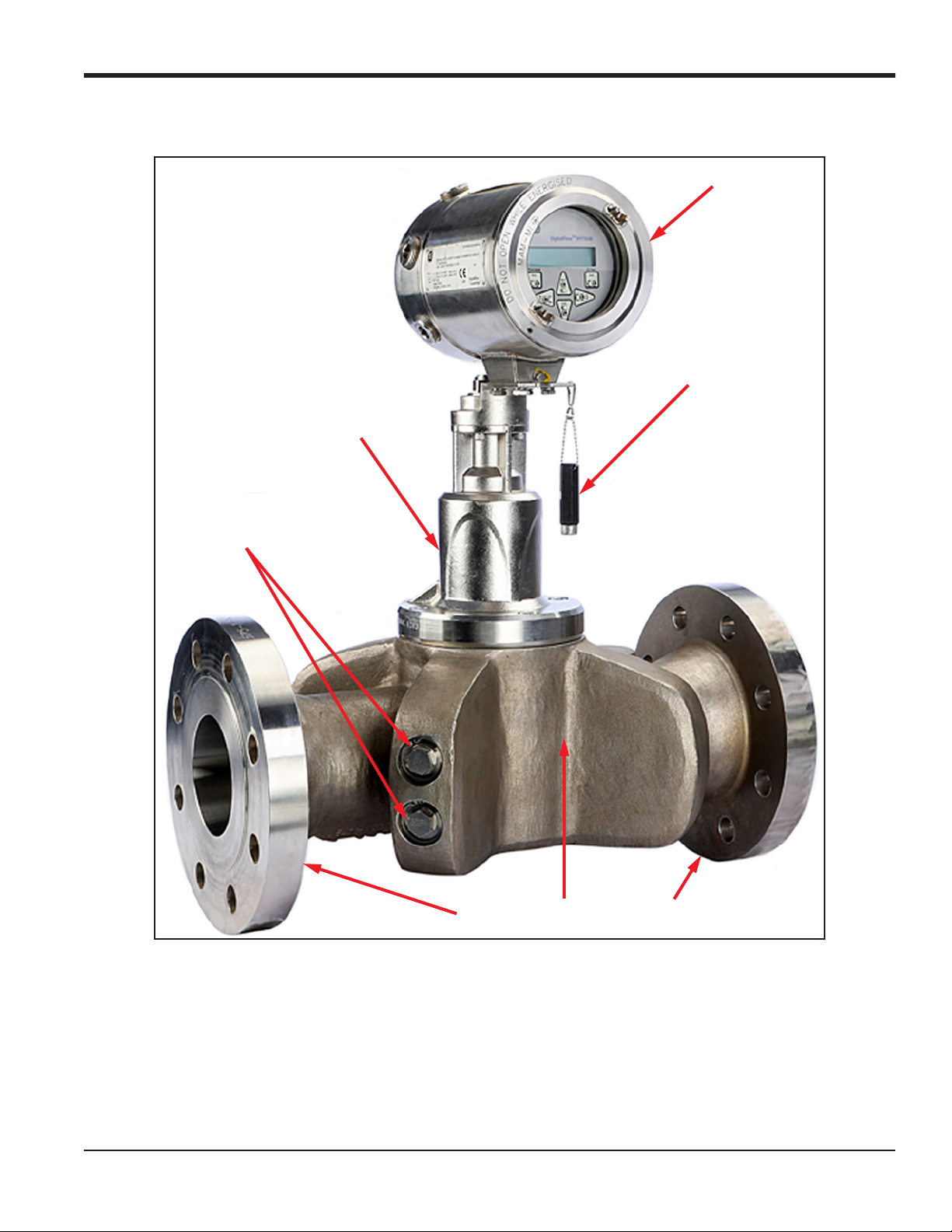
1.6 Meter Components (cont.)
Mounting Adapter (4)
Chapter 1. General Information
Transmitter Electronics (2)
Magnetic Stylus (3)
Transducer/Insert (5)
Figure 1: Typical PanaFlow Z1G/Z2G Process Gas Flowmeter Assembly
Meter Body with Flanges (1)
Note: Design details may vary slightly with pipe size.
PanaFlow™ Z1G/Z2G User’s Manual 3
Page 14

Chapter 1. General Information
1.7 Tag Plates
The PanaFlow Z1G/Z2G Process Gas Flowmeter is marked with a variety of labels which provide valuable
information about your specific system. Examples of typical flowcell tag plates are shown in the following
sections.
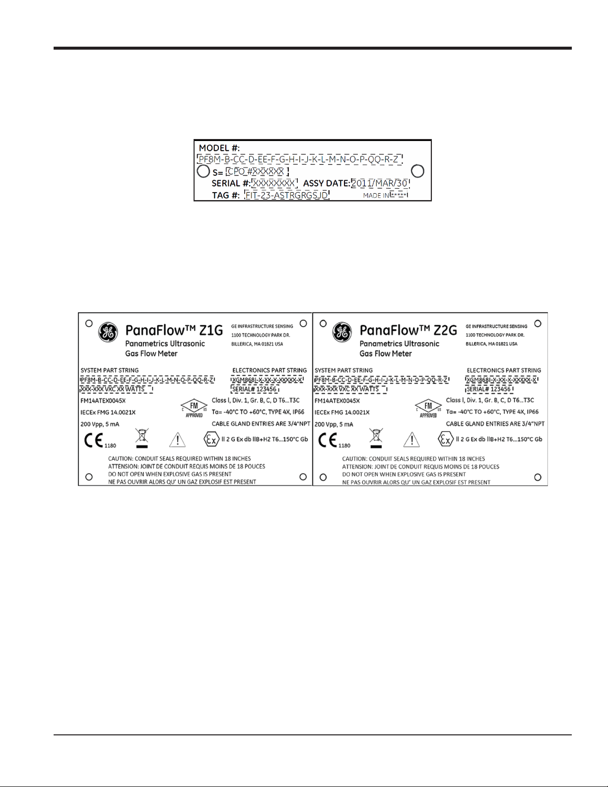
1.7.1 Model Tag Plate
The Model Tag Plate (see Figure 2 below) contains the model name and certification markings for the spool
and its hazardous area usage.
Figure 2: Model Tag Plate
1.7.2 Specification Tag Plate
The Specification Tag Plate (see Figure 3 below) contains information pertaining to the build and test of the
spool, such as spool nominal size, flange rating, wall thickness, material, dry weight (including transmitter),
vessel manufacturing serial number, ambient and fluid temperature ranges, operating pressures, hydro test
pressure and date.
Figure 3: Specification Tag Plate
4 PanaFlow™ Z1G/Z2G User’s Manual
Page 15
Chapter 1. General Information
1.7.3 Part String and Serial Number Tag Plate
The Part String and Serial Number Tag (see Figure 4 below) contains the specific configuration of the spool as
well as the final assembly date, BHGE serial number and customer tag number.
Figure 4: Part String and S/N Tag Plate
1.7.4 Transmitter Tag Plate
The Flow Transmitter Tag Plate (see Figure 5 below) is affixed to the transmitter and includes the
configuration per the model information detailed on the Model Tag Plate. This tag plate also contains the
hazardous area certification information for the transmitter.
Figure 5: Flow Transmitter Tag Plate
PanaFlow™ Z1G/Z2G User’s Manual 5
Page 16

Chapter 1. General Information
[no content intended for this page]
6 PanaFlow™ Z1G/Z2G User’s Manual
Page 17
Chapter 2. Installation
Chapter 2. Installation
2.1 Introduction
To ensure safe and reliable operation of the PanaFlow Z1G/Z2G Process Gas Flowmeter, the system must be
installed in accordance with the guidelines established by BHGE engineers. Those guidelines are explained
in detail in this chapter.
WARNING! The PanaFlow Z1G/Z2G Process Gas Flowmeter can measure the flow rate of many
gases, some of which are potentially hazardous. In such cases, the importance of proper safety
practices cannot be overemphasized.
Be sure to follow all applicable local safety codes and regulations for installing electrical equipment
and working with hazardous gases or flow conditions. Consult company safety personnel or local
safety authorities to verify the safety of any procedure or practice.
Attention! To meet CE Mark requirements for all units intended for use in the EU or in high
electrical noise environments, all electrical cables must be installed as described in Appendix A, “CE
Mark Compliance and High Noise Environments”.
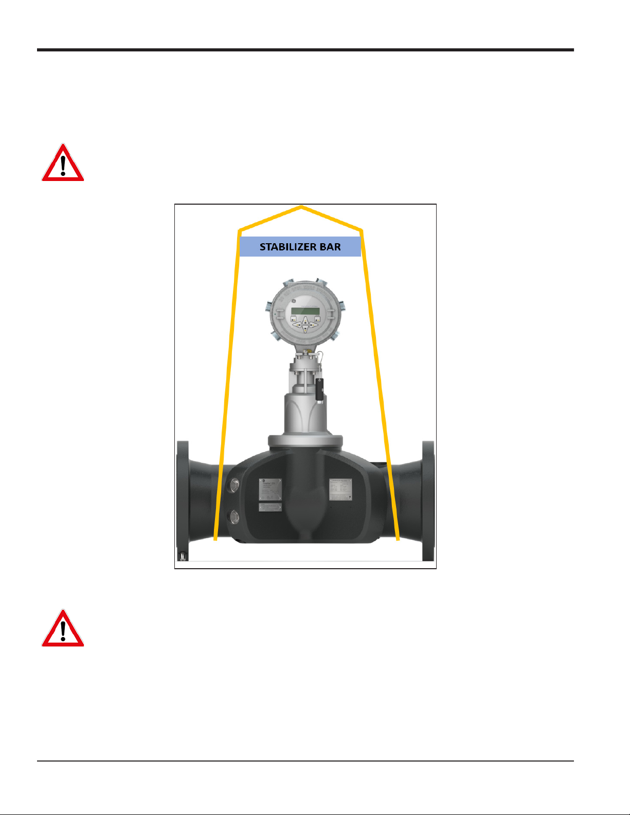
2.2 Lifting Instructions
Use proper lifting techniques when moving the PanaFlow Z1G/Z2G Process Gas Flowmeter. No lifting hooks or
eyelets are provided. The recommended method for lifting the PanaFlow Z1G/Z2G Process Gas Flowmeter is
by using lifting straps on each side of the spool with a stabilizer bar between them, located above the
transmitter head. Additional care may need to be taken to prevent the transmitter from rotating, especially
on the smaller systems where the transmitter weight is a larger percentage of the total system weight. A
label similar to Figure 6 below, which illustrates these required precautions, is attached to the flowcell.
Figure 6: Spoolpiece Lifting Label (ref. dwg. 442-1232)
PanaFlow™ Z1G/Z2G User’s Manual 7
Page 18
Chapter 2. Installation
2.2 Lifting Instructions (cont.)
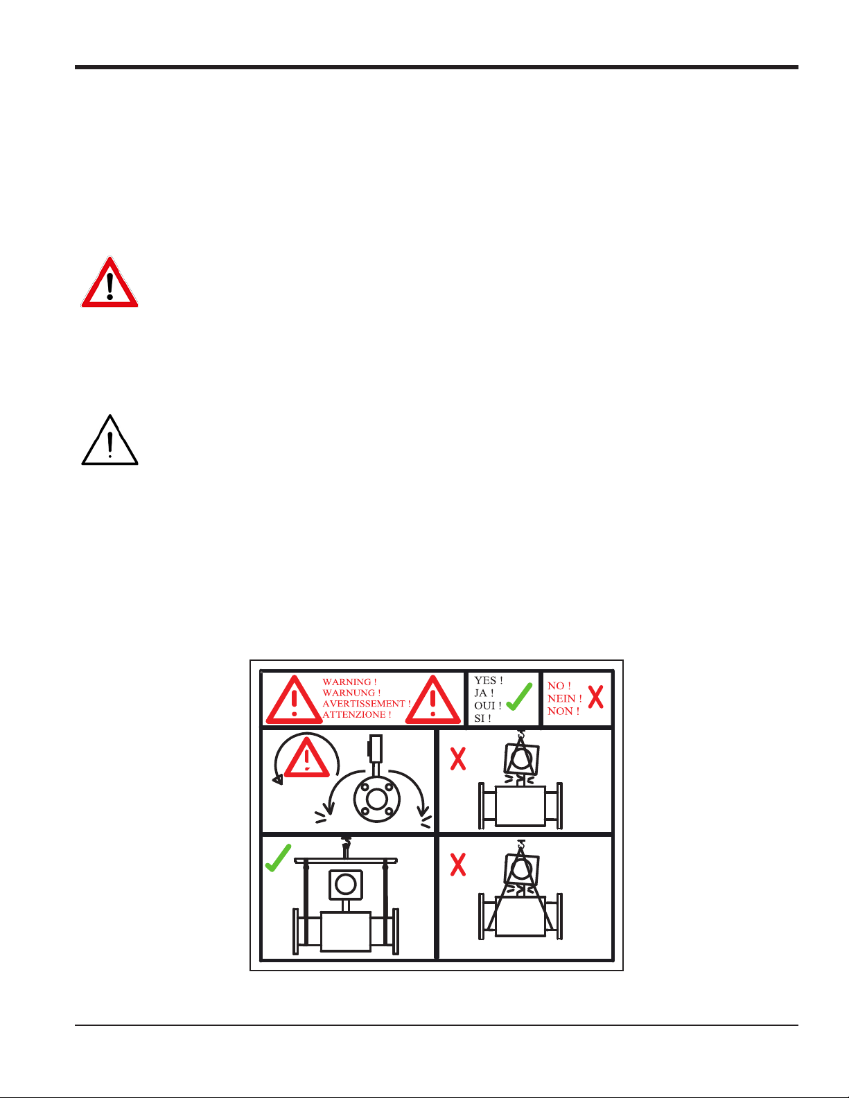
While lifting the PanaFlow Z1G/Z2G Process Gas Flowmeter, be sure to observe the warnings and figures
below:
WARNING! Never stand below any object being lifted.
Figure 7: Proper Lifting Method
WARNING! Do not use the transmitter to support the weight of the flowcell as shown in Figure 8
below. The transmitter cannot support the weight of the Flowcell/Spool.
8 PanaFlow™ Z1G/Z2G User’s Manual
Page 19
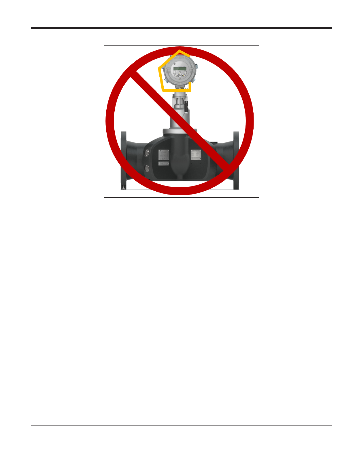
Chapter 2. Installation
Figure 8: Improper Lifting Method
2.3 Flowcell Location Guidelines
The flowcell includes the flow transducers and, optionally, pressure and temperature transmitters. Ideally,
install the flowcell in a section of pipe with access to the flowcell, such as a long run of pipe that is above
ground. Observe the following recommendations:
• There should be at least 20 pipe diameters of straight, undisturbed flow upstream and 10 pipe
diameters of straight, undisturbed flow downstream from the measurement point. To ensure
undisturbed flow, avoid sources of disturbances in the fluid such as valves, flanges, expansions, and
elbows.
• Because condensate or sediment at the bottom of the pipe may cause attenuation of the ultrasonic
signal, always install the PanaFlow Z1G/Z2G Process Gas Flowmeter with the transmitter in a vertical
orientation on the top of the pipe. This ensures that the transducers are located on the sides of the
pipe rather than on the top or bottom.
• Only authorized personnel should perform the installation. The proper personal protection
equipment (PPE) should always be used when working with this equipment.
• The flowcell shall be installed in such a way that it can be safely operated, maintained and inspected.
Please refer to specific outline and installation drawings for proper clearances and specific distances
for each system size. In general, allow for a minimum of 12” of space on all sides of the flowcell and
flow transmitter, with an ideal clearance of 24” on all sides.
• You must provide suitable over-pressure protection at the main piping to the flowcell in order to
prevent damage to the flowcell and injury to personnel. The utilized over-pressure protection device
shall be supplied with all declarations of conformity and EC-type design certificates.
PanaFlow™ Z1G/Z2G User’s Manual 9
Page 20
Chapter 2. Installation
• Make sure the difference between the inside diameter of the pipe and that of the PanaFlow Z1G/Z2G
Process Gas Flowmeter does not exceed 0.5%, as changes in internal diameters will cause flow profile
disturbances.
• Make sure any non-symmetrical offset does not exceed 1%, as misalignment between the piping and
the meter may cause flow profile disturbances.
• Make sure the gasket is centered on the flange faces and does not protrude into the pipe, as
protrusion of the gasket into the pipe may cause flow profile disturbances.
• If pipe insulation is required, install all insulation materials and accessories in accordance with the
manufacturer's instructions and recognized industry practices. Adhere to the local code where
applicable to ensure that the safe and proper installation will serve its intended purpose.
2.4 Making the Electrical Connections
This section contains instructions for making all the necessary electrical connections to the PanaFlow
Z1G/Z2G Process Gas Flowmeter. Refer to Figure 13 on page 19 for a complete wiring diagram.
Note: Except for the power connector, all electrical connectors are stored on their terminal blocks during
shipment and may be removed from the enclosure for more convenient wiring. Simply, feed the cables
through the conduit holes on the side of the enclosure, attach the wires to the appropriate connectors,
and plug the connectors back into their terminal blocks.
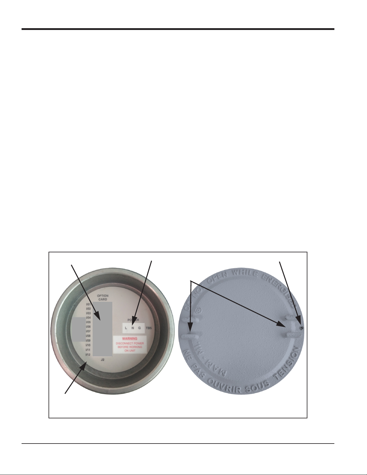
To prepare the PanaFlow Z1G/Z2G Process Gas Flowmeter for wiring, refer to Figure 9 below, and complete the
following steps:
Option Card Connections
Wiring Label
Power Connections
Slots
Set Screw
Inside View
Figure 9: Rear Cover with Connection Labels
10 PanaFlow™ Z1G/Z2G User’s Manual
Outside View
Page 21
Chapter 2. Installation
WARNING! Always disconnect the line power from the PanaFlow Z1G/Z2G Process Gas Flowmeter
electronics before removing either the front or rear cover. This is especially important in a hazardous
environment.
1. Disconnect any existing power line from its source.
2. Loosen the set screw on the rear cover.
3. Place a rod or long screwdriver across the cover in the slots provided, and rotate the cover
counterclockwise until it comes free from the enclosure.
4. Install any required cable clamps in the appropriate conduit holes around the side of the enclosure.
5. Refer to the labels inside the rear cover to assist in making the power and option card connections.
Also, Figure 14 on page 20 shows the specific connection labels for all available option cards.
2.4.1 Wiring the Line Power
The PanaFlow Z1G/Z2G Process Gas Flowmeter may be ordered for operation with power inputs of either
85-240 VAC (standard) or
12-28 VDC (optional). The tag plate on the side of the electronics enclosure lists the required line voltage and
the power rating. Be sure to connect the meter only to the specified line voltage.
WARNING! Proper grounding of the PanaFlow Z1G/Z2G Process Gas Flowmeter is required to
prevent the possibility of electric shock. See Figure 11 on page 17 for the location of the chassis
grounding screw.
WARNING! For compliance with the European Union’s Low Voltage Directive, this unit requires an
external power disconnect device such as a switch or circuit breaker. The disconnect device must be
marked as such, clearly visible, directly accessible, and located within 1.8 m (6 ft) of the meter.
WARNING! Improper connection of the line power leads or connecting the meter to the incorrect
line voltage may damage the unit. It may also result in hazardous voltages at the flowcell and
associated piping as well as within the electronics enclosure.
Refer to Figure 13 on page 19 to locate the correct terminal block, and connect the line power as follows:
1. Prepare the line power leads by trimming the line and neutral AC power leads (or the positive and
negative DC power leads) to a length 0.5 in. (1 cm) shorter than the ground lead. This ensures that the
ground lead is the last to detach if the power cable is forcibly disconnected from the meter.
2. Install a cable clamp in the conduit hole closest to the power terminal block. Avoid using the other
conduit holes for this purpose to minimize any interference in the circuitry from the AC power line.
3. Strip 1/4 in. of insulation from the end of each of the three power line leads.
4. Route the cable through the conduit hole and connect the line power leads to the terminal block,
using the pin number assignments shown in Figure 13 on page 19.
5. Leaving a bit of slack, secure the power line with the cable clamp.
PanaFlow™ Z1G/Z2G User’s Manual 11
Page 22
Chapter 2. Installation
WARNING! Make sure both covers, with their o-ring seals, are installed and the set screws
tightened before applying power in a hazardous environment.
CAUTION! The transducers must be properly wired before applying power to the meter.
(If the electronics enclosure is mounted directly on the flowcell, these connections are made at the
factory prior to shipment.)
Proceed to the next section to continue the wiring of the PanaFlow Z1G/Z2G Process Gas Flowmeter.
2.4.2 Wiring the Transducers
Attention! To meet CE Mark requirements for all units intended for use in the EU or in high
electrical noise environments, all electrical cables must be installed as described in Appendix A, “CE
Mark Compliance and High Noise Environments”.
For a PanaFlow Z1G/Z2G Process Gas Flowmeter system with the flow transmitter mounted on the flowcell,
no external transducer wiring is required. However, for a system with a remote mounted flow transmitter,
refer to the wiring diagram in Figure 12 on page 18 to connect the transducers and preamplifiers to the
transmitter.
2.4.3 Wiring the Standard 4-20 mA Analog Outputs
The standard configuration of the PanaFlow Z1G/Z2G Process Gas Flowmeter includes two isolated 4-20 mA
analog outputs (designated as outputs 1 and 2). Connections to these outputs may be made with standard
twisted-pair wiring, but the current loop impedance for these circuits must not exceed 600
Attention! To meet CE Mark requirements for all units intended for use in the EU or in high
electrical noise environments, all electrical cables must be installed as described in Appendix A, “CE
Mark Compliance and High Noise Environments”.
To wire the analog outputs, complete the following steps:
1. Disconnect the main power and remove the rear cover.
2. Install a cable clamp in the chosen conduit hole on the side of the electronics enclosure.
3. Refer to Figure 13 on page 19 to locate the correct terminal block, and wire the analog outputs as
shown. Secure the cable clamp.
Note: Analog outputs 1 and 2 in the wiring diagram correspond to analog outputs A and B in Slot 0 in the
Panaview software.
4. If wiring of the unit has been completed, reinstall the rear cover on the enclosure and tighten the set
screw.
Ω.
WARNING! Make sure both covers, with their o-ring seals, are installed and the set screws
tightened before applying power in a hazardous environment.
12 PanaFlow™ Z1G/Z2G User’s Manual
Page 23
Chapter 2. Installation
Note: Prior to use, the analog outputs must be set up and calibrated.
Proceed to the next section to continue the wiring of the PanaFlow Z1G/Z2G Process Gas Flowmeter.
2.4.4 Wiring the Standard RS485 Serial Port
The PanaFlow Z1G/Z2G Process Gas Flowmeter is equipped with a standard RS485 serial interface. This serial
port will be used to communicate with PC/DCS system. In addition, the PanaFlow Z1G/Z2G Process Gas
Flowmeter can receive and execute remote commands, using BHGE’s PanaView software.
Note: For more detailed information on serial communications refer to BHGE’s EIA-RS Serial
Communications manual (document #916-054).
Attention! To meet CE Mark requirements for all units intended for use in the EU or in high
electrical noise environments, all electrical cables must be installed as described in Appendix A, “CE
Mark Compliance and High Noise Environments”.
Refer to Figure 13 on page 19 to locate the correct terminal block, and wire the RS485 serial port as follows:
WARNING! Always disconnect the line power from the PanaFlow Z1G/Z2G Process Gas Flowmeter
electronics before removing either the front or rear cover. This is especially important in a hazardous
environment.
1. Disconnect the main power and remove the rear cover.
2. Install the required cable clamp in the chosen conduit hole on the side of the electronics enclosure.
3. Feed one end of the cable through the conduit hole, wire it to terminal block, and secure the cable
clamp. Use the information in Table 2 below to prepare a suitable cable for connecting the PanaFlow
Z1G/Z2G Process Gas Flowmeter to the external serial device.
Table 2: RS485 Cable Connections
TB Pin # Signal Description
1 RS485+
2 RS485-
3COM
4 Not Used
5 Not Used
4. If wiring of the unit has been completed, reinstall the rear cover on the enclosure and tighten the set
screw.
Proceed to the next section to continue the wiring of the PanaFlow Z1G/Z2G Process Gas Flowmeter.
2.4.5 Wiring the Option Cards
The PanaFlow Z1G/Z2G Process Gas Flowmeter can accommodate two option cards one in Slot 1 and other
option card in Slot 2. The following option card functions are available only in certain combinations.
PanaFlow™ Z1G/Z2G User’s Manual 13
Page 24

Chapter 2. Installation
• Analog Inputs (Slot 1)
• RTD Inputs (Slot 1)
• Modbus Communications (Slot 2)
• HART Communications (Slot 2)
• Foundation Fieldbus Communications (Slot 2)
Figure 14 on page 20 shows the connection labels for the available option cards. Wiring any option card
installed in Slot 1 requires completion of the following steps:
Attention! To meet CE Mark requirements for all units intended for use in the EU or in high
electrical noise environments, all electrical cables must be installed as described in Appendix A, “CE
Mark Compliance and High Noise Environments”.
1. Disconnect the main power and remove the rear cover.
2. Install a cable clamp in the chosen conduit hole on the side of the electronics enclosure and feed a
standard twisted-pair cable through this conduit hole.
3. Locate the 12-pin terminal block in Figure 13 on page 19 and wire the option card as indicated on the
label inside the rear cover (see Figure 9 on page 10). Secure the cable clamp.
IMPORTANT: If you have multiple flow transmitters, because of the attached wiring label, all rear covers
remain with their original meters!
4. If wiring of the unit has been completed, reinstall the rear cover on the enclosure and tighten the set
screw.
IMPORTANT: Prior to use, the option card must be set up and calibrated.
For more specific instructions on particular option cards, proceed to the appropriate section(s) that follow.
must
14 PanaFlow™ Z1G/Z2G User’s Manual
Page 25

Chapter 2. Installation
2.4.5.1 Wiring a 4-20 mA Analog Inputs Option Card
To calculate standard flow rates, the PanaFlow Z1G/Z2G Process Gas Flowmeter requires accurate
temperature and pressure data from the measurement site. Transmitters installed in the flowcell can provide
this information via an optional4-20 mA analog inputs option card. This option card includes two or four
isolated 4-20 mA analog inputs (designated as A, B, C and D), each of which includes a 24 VDC power supply
for loop-powered transmitters. Either input may be used to process the temperature signal, while the other
input is used to process the pressure signal.
IMPORTANT: To properly enter programming data into the meter, it is necessary to know which input is
assigned to which process parameter.
The analog inputs, which have an impedance of 118
Ω, should be connected with standard twisted-pair
wiring. Power to the transmitters may be supplied either by the integral 24 VDC power supply on the analog
input option card or by an external power supply. Figure 10 below shows typical wiring diagrams, with and
without an external power supply, for one of the analog inputs.
24 VDC
POWER SUPPLY
+–
Analog Input
INPUT +
+24V
Transmitter
+ IN
– OUT
With External Power Supply With Internal Power Supply
Sensor
Analog Input
INPUT +
+24V
Transmitter
– OUT
+ IN
Sensor
Figure 10: Typical Analog Input Wiring Diagrams
Before making any connections, complete the steps in “Making the Electrical Connections” on page 10. Then,
wire the analog inputs as shown on the label in the rear cover (see Figure 9 on page 10).
IMPORTANT: The analog inputs option card can be calibrated with the PanaFlow Z1G/Z2G Process Gas
Flowmeter’s built-in analog outputs. However, be certain that the analog outputs have been
calibrated first.
PanaFlow™ Z1G/Z2G User’s Manual 15
Page 26

Chapter 2. Installation
2.4.5.2 Wiring an RTD Inputs Option Card
The PanaFlow Z1G/Z2G Process Gas Flowmeter RTD inputs option card provides two or four direct RTD inputs
(designated as A, B, C and D). Each RTD input requires three wires, and should be connected as shown on the
label in the rear cover (see Figure 9 on page 10).
Before making any connections, complete the steps in “Making the Electrical Connections” on page 10.
2.4.5.3 Wiring a Modbus Option Card
A Modbus option card uses the RS485 standard for communication, and it must be installed in Slot 2. The
RS485 standard allows up to 32 nodes (drivers and receivers) on one multi-drop network, at distances up to
4000 ft (1200 m). BHGE recommends using 24-gauge (24 AWG) twisted-pair wire with a characteristic
impedance of 120
Note: The Modbus option card provides its own RS485 connections.
Ω and 120 Ω termination at each end of the communications line.
2.4.5.4 Wiring The HART Interface
To connect the HART interface, refer to Figure 13 on page 19 and proceed as follows:
1. Connect the HART Net (+) wire to pin #1.
2. Connect the HART Net (-) wire to pin #2.
3. Connect the optional cable shield to pin #3.
2.4.5.5 Wiring the Foundation Fieldbus Interface
To connect the Foundation Fieldbus interface, refer to Figure 13 on page 19 and proceed as follows:
1. Connect the Fieldbus Net (+) wire to pin #1.
2. Connect the Fieldbus Net (-) wire to pin #2.
3. Connect the optional cable shield to pin #3.
WARNING! Make sure both covers, with their o-ring seals, are installed and the set screws
tightened before applying power in a hazardous environment.
16 PanaFlow™ Z1G/Z2G User’s Manual
Page 27

Chapter 2. Installation
PanaFlow™ Z1G/Z2G User’s Manual 17
D
S
O
R
U
V
I
R
N
E
P
A
T
U
O
S
S
E
O
I
N
S
N
O
P
O
O
T
N
E
N
W
H
S
E
D
E
R
N
E
I
L
E
G
I
Ø6.10 (155)
8.20
2.06
51°
7 PLCS
3/4" NPTF
7 PLCS
3.86
SEE
A A
VIEW A-A
0.52 (13)
DETAIL A
3/4" NPT
1/4-20 UNC-2B
1.50
1.00
0.28 (7)
0.25 (6)
10-32 EXTERNAL GROUND SCREW
4PLCS
3/4" NPTF
7 PLCS
(52)
(98)
(208)
(38)
NOTES:
1. ALL DIMENSIONS ARE REFERENCE.
2. WEIGHT: 10 LB (4.5 KG) AL
25 LB (11.5 KG) SS
3. DIMENSIONS ARE IN INCHES (MILLIMETERS).
(25)
DETAIL A
Figure 11: Transmitter Electronics Enclosure - Outline & Dimensions (ref. dwg. 712-1318)
Page 28

Chapter 2. Installation
PanaFlow™ Z1G/Z2G User’s Manual 18
Figure 12: Remote Mount Electronics - Transducer and Preamplifier Wiring (ref. dwg. 702-731, 732)
Page 29

Chapter 2. Installation
PanaFlow™ Z1G/Z2G User’s Manual 19
COM (SHIELD)
1
3
2
TX (RS485+)
RX (RS485-)
CTS
DTR
AOUTB-
AOUTB+
AOUTA-
AOUTA+
I/O1
I/O2
I/O3
I/O4
I/O5
I/O6
I/O7
I/O8
I/O9
I/1O
I/11
I/12
CH1UP
CH1RTN
CH1RTN
CH1DN
CH2UP
CH2RTN
CH2RTN
CH2DN
OPTION CONTACT TERMINAL BLOCK
4-20 OUTPUT 1 SIG
4-20 OUTPUT 1 RTN
4-20 OUTPUT 2 SIG
4-20 OUTPUT 2 RTN
DATA TERMINAL READY
CLEAR TO SEND
COMMON
TRANSMIT
DESCRIPTION
RS232/RS485/4-20 ANALOG OUTPUT TERMINAL BLOCK
PIN
5 DTR
4 CTS
3 COM (SHLD)
7 AOUT B+
6 AOUT B-
9 AOUT A+
8 AOUT A-
2 RX (RS485 -)
1 TX (RS485 +)
RECEIVE
CH1 DOWNSTREAM TRANSDUCER ANALOG RTN (-)
CH1 UPSTREAM TRANSDUCER SIG (+)
CH1 UPSTREAM TRANSDUCER ANALOG RTN (-)
CH1 DOWNSTREAM TRANSDUCER SIG (+)
DESCRIPTION
LINE POWER CONNECTION
NEUTRAL CONNECTION
EARTH GROUND CONNECTION
CH1 TRANSDUCER CONNECTION TERMINAL BLOCK
AC WIRING SHOWN
1 CH1UP
3 CH1RTN
2 CH1RTN
4 CH1DN
PIN
1 L
PIN
3 G
2 N
DESCRIPTION
SUPPLY VOLTAGE
85V TO 250VAC
CH2 DOWNSTREAM TRANSDUCER ANALOG RTN (-)
CH2 UPSTREAM TRANSDUCER SIG (+)
CH2 UPSTREAM TRANSDUCER ANALOG RTN (-)
CH2 DOWNSTREAM TRANSDUCER SIG (+)
CH2 TRANSDUCER CONNECTION TERMINAL BLOCK
1 CH2UP
3 CH2RTN
2 CH2RTN
4 CH2DN
PIN
DESCRIPTION
OPTIONAL
N/C
MODBUS +
MODBUS -
MODBUS CONNECTION
1 +
3 N/C
2 -
PIN
DESCRIPTION
OPTIONAL
OPTIONAL SHIELD
FIELDBUS NET (+)
FIELDBUS NET (-)
FOUNDATION FIELDBUS
1 +
3 SHIELD
2 -
PIN
DESCRIPTION
OPTIONAL
DC WIRING (OPTIONAL)
OR 12 TO 28 VDC
OPTIONAL SHIELD
HART NET (+)
HART NET (-)
HART
1 +
3 SHIELD
2 -
PIN
DESCRIPTION
OPTIONAL
Figure 13: Transmitter Electronics - Wiring Diagram (ref. dwg. #702-1846)
Page 30

Chapter 2. Installation
PanaFlow™ Z1G/Z2G User’s Manual 20
-05 (CI,TI,FI)
-09 (OI)
-08 (AI,HI)
11
12
9
10
7
8
2
4
5
6
3
Pin 1
9
11
12
10
7
8
6
5
3
4
Pin 1
2
12
11
10
9
8
7
2
4
5
6
3
Pin 1
R = RTD Input
A = Standard Alarm
H = Hermetic Alarm
F = Frequency Output
T = Totalizer Output
I = Current Input
C = Current Output
O = Blank/No Connection
NOTE:
Figure 14: Labels - Option Card Connections
Page 31

Chapter 3. Initial Setup
Chapter 3. Initial Setup
3.1 Introduction
This chapter provides instructions for programming the data required to place the PanaFlow Z1G/Z2G
Process Gas Flowmeter into operation. Before the PanaFlow Z1G/Z2G Process Gas Flowmeter can begin taking
measurements and displaying valid data, the current system and pipe parameters must be entered.
Additional programming options provide access to the more advanced features of the PanaFlow Z1G/Z2G
Process Gas Flowmeter, but this information is not required to begin taking measurements.
Note: Be sure to record all programming data in Appendix B, “Gas Process Flowmeter Service Record”.
As a guide in following the programming instructions in this chapter, see Figure 16 on page 31 for the
relevant portions of the PanaFlow Z1G/Z2G Process Gas Flowmeter menu map.
3.2 Programming Methods
You can program the PanaFlow Z1G/Z2G Process Gas Flowmeter with the magnetic keypad on the electronics
enclosure, or with PanaView™, BHGE’s PC-based non-resident software program that communicates with
the PanaFlow Z1G/Z2G Process Gas Flowmeter via its serial port. PanaView provides additional programming
capabilities, such as:
• Load and save site file data
• Create and save graph and log files
• Display text output and graphs of live measurement data
• Create custom templates for displaying text, graph, and log data
• Interface with multiple BHGE instruments.
This chapter focuses on programming via the magnetic keypad. For information on programming the
PanaFlow Z1G/Z2G Process Gas Flowmeter via PanaView, refer to the PanaView User’s Manual (BHGE
document #910-211).
PanaFlow™ Z1G/Z2G User’s Manual 21
Page 32

Chapter 3. Initial Setup
3.3 The Magnetic Keypad
The glass window on the electronics enclosure includes the components shown in Figure 15 below.
Figure 15: Display and Magnetic Keypad
IMPORTANT: The PanaFlow Z1G/Z2G Process Gas Flowmeter magnetic keypad enables programming of the
instrument through the glass faceplate without removing the cover. Thus, all programming
procedures may be performed while the unit is installed in a hazardous area.
The six keys on the magnetic keypad (see Table 3 below) enable users to program the PanaFlow Z1G/Z2G
Process Gas Flowmeter.
Table 3: Keypad Keys and Functions
Key Key Name Functions
Escape Key To cancel a numeric entry change, or exit a menu or as Back key
Enter Key To accept a numeric entry or select a menu option
Left Arrow Key To navigate among menu choices or to set cursor position
Right Arrow Key To navigate among menu choices or to set cursor position
Up Arrow Key To navigate among menu choices or to Increment numeric entries
Down Arrow Key To navigate among menu choices or to Decrement numeric entries
22 PanaFlow™ Z1G/Z2G User’s Manual
Page 33

Chapter 3. Initial Setup
3.4 Initial Power On Screens
When you power On the PanaFlow Z1G/Z2G Process Gas Flowmeter, the display first shows the model name
and software version:
GE
XGM868i Y4FM.SP1
The meter then starts to display measured parameters.
Ch1 VEL
0.00 m/s
To enter the Keypad Program, press the [
successive key must be entered within 10 seconds of the prior key.
As a guide in following the programming instructions in this chapter, the relevant portions of the PanaFlow
Z1G/Z2G Process Gas Flowmeter menu map can be found in Figure 16 on page 31. Proceed to the following
sections to enter data in the Channel or GLOBL menus.
IMPORTANT: If the keypad has not been pressed for 10 minutes, the PanaFlow Z1G/Z2G Process Gas
Flowmeter exits the Keypad Program and returns to displaying measurements. The meter
retains any configuration changes that were confirmed with the [
programming had been completed.
] key, followed by the [] key, and the [] key again. Each
] key, and restarts as if the
PanaFlow™ Z1G/Z2G User’s Manual 23
Page 34

Chapter 3. Initial Setup
3.5 Entering Data in the GLOBL Menu
To begin programming your meter, you must select the system units from the GLOBL menu as discussed
below. Refer to Figure 16 on page 31 and remember to record all programming data in Appendix B, “Gas
Process Flowmeter Service Record”.
3.5.1 Entering Global System Data
The GLOBL-SYSTM submenu is used to enter several general system parameters (e.g., English or metric units).
For meters with 2 channels, this menu is also used to compute parameters such as the sum, difference or
average of the channel 1 and channel 2 signals. When calculating the SUM, DIF or AVE readouts, data from the
GLOBL-SYSTM submenu is used. Any conflicting data entered in the CHANNEL-SYSTM submenu is overridden.
Complete the following steps:
1. In the Keypad Program, scroll to PROG and press [
2. In the PROG menu, scroll to GLOBL and press [
3. In the Global PROGRAM menu, scroll to SYSTM and press [
4. Scroll to the desired System Units selection (either metric or English) and press [
parameters and measurements in the designated units.
5. Scroll to the desired Pressure Units selection (absolute or gauge) and press [
6. Do one of the following:
].
].
].
].
• If PSIa (absolute) was selected, skip this step.
• If PSIg (gauge) was selected, enter the desired atmospheric pressure and press [].
7. The program automatically returns to the Global PROGRAM menu.
] to display all
24 PanaFlow™ Z1G/Z2G User’s Manual
Page 35

Chapter 3. Initial Setup
3.5.2 Selecting Volumetric Units
1. Scroll to the desired Volumetric Units for the flow rate display and press []. Table 4 below lists the
available volumetric units.
Table 4: Available Volumetric/Totalizer Units
English Metric
ACF = Actual Cubic Feet ACM = Actual Cubic Meters
KACF = Thousands of ACF KACM = Thousands of ACM
MMACF = Millions of ACF MMACM = Millions of ACM
SCF = Standard Cubic Feet SCM = Standard Cubic Meters
KSCF = Thousands of SCF KSCM = Thousands of SCM
MMSCF = Millions of SCF MMSCM = Millions of SCM
2. Scroll to the desired unit of Volumetric Time (from seconds to days) and press [].
3. Scroll to the desired number of Vol Decimal Digits (digits to the right of the decimal point) in the
volumetric flow display and press [
].
3.5.3 Selecting Totalizer Units
4. Scroll to the desired Totalizer Units for the flow rate display and press []. Available units are listed
in Table 4 above.
5. Scroll to the desired number of Tot Decimal Digits (digits to the right of the decimal point in the
totalized flow rate display) and press [
6. Do one of the following:
].
• If MASS FLOW is ON, proceed to “Selecting Mass Flow Units” on page 26.
• If MASS FLOW is OFF, the meter returns to the Global PROGRAM window. Press [] twice and proceed
to
Chapter 4, “Operation”.
Note: The following prompts appear only if Mass Flow is activated for both channels.
PanaFlow™ Z1G/Z2G User’s Manual 25
Page 36

Chapter 3. Initial Setup
3.5.4 Selecting Mass Flow Units
1. Scroll to the desired Mass Flow units for the flow rate display and press []. The available units for
this prompt are determined by the selection made at the System Units screen. See Table 5 below for
the available units.
Table 5: Available Mass Flow Units
English Metric
LB = Pounds Kilograms
KLB = Thousands of LB Metric Tons (1000 KG)
MMLB = Millions of LB
Tons (2000 LB)
2. Scroll to the desired Mass Flow Time units for the mass flow rate display (from seconds to days) and
press [
3. Scroll to the desired number of Mdot Dec. Digits (digits to the right of the decimal point in the mass
flow rate display) and press [
].
].
4. Scroll to the desired Mass (Totalizer) units for the totalized mass flow rate display and press [
available units for this prompt are determined by the selection made at the System Units prompt.
5. Scroll to the desired number of Mass Dec. Digits (digits to the right of the decimal point in the
totalized mass flow rate display) and press [
6. After completing the above steps, the PanaFlow Z1G/Z2G Process Gas Flowmeter returns to the Global
PROGRAM window. Press [
] and scroll to CH1 or CH2 to continue the initial setup programming.
].
]. The
26 PanaFlow™ Z1G/Z2G User’s Manual
Page 37

Chapter 3. Initial Setup
3.6 Activating a Channel
The Channelx-ACTIV submenu permits selection of the desired measurement method. In addition, it is used
to activate/deactivate one or both of the channels in a 2-Channel PanaFlow Z1G/Z2G Process Gas Flowmeter.
To access the Channelx-ACTIV submenu, proceed as follows:
1. From the Keypad Program, scroll to CH1 or CH2 and press [
2. In the Channel PROGRAM menu, scroll to ACTIV and press [
3. Scroll to Burst to activate the channel/path, and press [
Note: Burst is automatically selected for a 1-Channel meter.
4. Scroll to one of the measurement methods described below and press [
].
].
].
].
• Skan Only is the preferred technique for locating the acoustic signal and for high velocity measurements. It
is more robust in a noisy environment than the Measure technique.
• Skan/Measure is the preferred technique to use for low velocity measurements.
If Skan Only is selected at the above prompt, the meter uses this technique exclusively. However, if
Skan/Measure is selected, the meter uses Skan Only to find the acoustic signal and then tries to use the
Skan/Measure technique for the actual measurement.
After completing the above step, the meter returns to the Channel PROGRAM menu. Proceed to the next
section to continue programming your meter.
PanaFlow™ Z1G/Z2G User’s Manual 27
Page 38

Chapter 3. Initial Setup
3.7 Entering System Data for a Channel
The Channelx-System submenu is used to enter system parameters for the channel.
3.7.1 Accessing the Channelx-System Submenu
1. From the Channel PROGRAM menu, scroll to SYSTM and press [].
2. The first prompt asks for the Channel Label.Use the four arrow keys to enter the desired label (in any
numeric or text combination up to five characters), and then press [
3. The next prompt asks for the Channel (Site) Message. Enter the desired text in the same manner as the
channel label with up to 15 characters, and then press [
].
3.7.2 Selecting Volumetric Units
1. Scroll to the desired Volumetric Units for the flow rate display and press []. the available units are
listed in Table 6 below.
2. Scroll to the desired Volumetric Time units for the flow rate display (from seconds to days) and press
[
].
].
3. Scroll to the desired number of Vol Decimal Digits (digits to the right of the decimal point in the
volumetric flow rate display) and press [
Table 6: Available Volumetric/Totalizer Units
English Metric
ACF = Actual Cubic Feet ACM = Actual Cubic Meters
KACF = Thousands of ACF KACM = Thousands of ACM
MMACF = Millions of ACF MMACM = Millions of ACM
SCF = Standard Cubic Feet SCM = Standard Cubic Meters
KSCF = Thousands of SCF KSCM = Thousands of SCM
MMSCF = Millions of SCF MMSCM = Millions of SCM
].
3.7.3 Selecting Totalizer Units
1. Scroll to the desired Totalizer Units for the totalized flow rate display and press []. The available
units are listed in Table 6 above.
2. Scroll to the desired number of Tot Decimal Digits (digits to the right of the decimal point in the
totalized flow rate display) and press [
3. Do one of the following:
].
• If MASS FLOW is ON, proceed to “Selecting Mass Flow Units” on page 29.
• If MASS FLOW is OFF, the meter returns to the Channel PROGRAM menu.
28 PanaFlow™ Z1G/Z2G User’s Manual
Page 39

Chapter 3. Initial Setup
3.7.4 Selecting Mass Flow Units
1. Scroll to the desired Mass Flow units for the flow rate display and press []. The available units for
this prompt are determined by the selection made at the System Units prompt (see Table 7 below).
Table 7: Available Mass Flow Units
English Metric
LB = Pounds Kilograms
KLB = Thousands of LB Metric Tons (1000 KG)
MMLB = Millions of LB
Tons (2000 LB)
2. Scroll to the desired Mass Flow Time units for the mass flow rate display and press [].
3. Scroll to the desired number of Mdot Decimal Digits (digits to the right of the decimal point in the mass
flow rate display) and press [
].
4. Scroll to the desired Mass (Totalizer) units for the totalized mass flow rate display and press [
available units for this prompt are determined by the selection made at the System Units prompt.
5. Scroll to the desired number of Mass Dec. Digits (digits to the right of the decimal point in the totalized
mass flow rate display) and press [
After completing the above steps, the PanaFlow Z1G/Z2G Process Gas Flowmeter returns to the Channel
PROGRAM menu.
].
]. The
PanaFlow™ Z1G/Z2G User’s Manual 29
Page 40

Chapter 3. Initial Setup
[no content intended for this page]
30 PanaFlow™ Z1G/Z2G User’s Manual
Page 41

Chapter 3. Initial Setup
PanaFlow™ Z1G/Z2G User’s Manual 31
[Esc][Enter][Esc]
PROG RESET CALIB
CNTRS
NO YES
Reset Totals
See Service
Manual
DARKN LITEN
STORE ABORT
CH2* GLOBLCH1
(* for 2-Channel meter only)
I/O COMMSYSTM
I/O SETUP
SYSTMACTIV
Off
Burst Burst
1-CH meter2-CH meter
Channel Status
Site Status
Skan Only
Skan/Measure
Skan/Measure Mode
Volumetric Units
Channel Label
Site/Channel Message
MetricEnglish
ACF KACF MMACF
SCF KSCF MMSCF
ACM KACM MMACM
SCM KSCM MMSCM
/SEC /MIN /HR /DAY
Volumetric Time
0
1 2
3
Vol. Dec.Digits
Totalizer Units
0
1 2
3
Tot. Dec.Digits
MetricEnglish
Mass Flow Units
Mass Flow OFFMass Flow ON
LB KLB MMLB TONS KG TONNE
MetricEnglish
/SEC
/MIN /HR /DAY
Mass Flow Time
0
1 2
3
MDOT Dec.Digits
Mass Totals
LB KLB MMLB TONS KG TONNE
0 1 2 3
Mass Dec.Digits
MetricEnglish
ACF KACF MMACF
SCF KSCF MMSCF
ACM KACM MMACM
SCM KSCM MMSCM
Volumetric Units
1-Channel Units
2-Channel Units
MetricEnglish
ACF KACF MMACF
SCF KSCF MMSCF
ACM KACM MMACM
SCM KSCM MMSCM
/SEC /MIN /HR /DAY
Volumetric Time
0
1 2
3
Vol. Dec.Digits
Totalizer Units
0
1 2
3
Totalizer Decimal Digits
MetricEnglish
ACF KACF MMACF
SCF KSCF MMSCF
ACM KACM MMACM
SCM KSCM MMSCM
MetricEnglish
Mass Flow Off
LB
KLB MMLB TONS KG TONNE
MetricEnglish
/SEC
/MIN /HR /DAY
Mass Flow Time
0
1 2
3
MDOT Dec.Digits
Mass Totals
LB KLB MMLB TONS KG TONNE
Mass Dec.Digits
English
Metric
PSia
PSig
BARa
BARg Kpaa Kpag
Meter Message
System Units
Pressure Units
Atmospheric
Pressure
ATM
Pressure
ATM
Pressure
Mass Flow On
0
1 2
3
English
Metric
Figure 16: PanaFlow Z1G/Z2G Menu Map
Page 42

Chapter 3. Initial Setup
PanaFlow™ Z1G/Z2G User’s Manual 32
[no content intended for this page]
Page 43

Chapter 4. Operation
Chapter 4. Operation
4.1 Introduction
See Chapter 2, “Installation”, and Chapter 3, “Initial Setup”, to prepare your PanaFlow Z1G/Z2G Process Gas
Flowmeter system for operation. When the meter is ready to take measurements, proceed with this chapter.
The following specific topics are discussed:
• “Powering Up” on page 34
• “The PanaFlow Z1G/Z2G Process Gas Flowmeter LCD Display” on page 35
• “The Optional PanaView Display” on page 36
• “Taking Measurements” on page 37
Note: All inputs and outputs of the PanaFlow Z1G/Z2G Process Gas Flowmeter are calibrated at the factory
prior to shipment. If it becomes necessary to recalibrate any of the inputs and/or outputs, consult the
factory for instructions.
WARNING! To ensure the safe operation of the PanaFlow Z1G/Z2G Process Gas Flowmeter, it must
be installed and operated as described in this manual. In addition, be sure to follow all applicable local
safety codes and regulations for the installation of electrical equipment.
PanaFlow™ Z1G/Z2G User’s Manual 33
Page 44

Chapter 4. Operation
4.2 Powering Up
Because the PanaFlow Z1G/Z2G Process Gas Flowmeter does not have an ON/OFF switch, it will power up as
soon as the connected power source is energized.
WARNING! For compliance with the European Union’s Low Voltage Directive, this unit requires an
external power disconnect device such as a switch or circuit breaker. The disconnect device must be
marked as such, clearly visible, directly accessible, and located within 1.8 m (6 ft) of the meter.
There are three methods for obtaining readings from the PanaFlow Z1G/Z2G Process Gas Flowmeter:
• Built-in PanaFlow Z1G/Z2G Process Gas Flowmeter LCD display
• PanaView software installed on a personal computer
• External analog device to read the PanaFlow Z1G/Z2G Process Gas Flowmeter analog output
At least one of the above display options must be installed in order to obtain flow rate readings from the
meter.
Immediately upon power up, the software version display appears. Then, the meter performs a series of
internal checks, which take about 45 seconds, prior to displaying the flow rate data (see“Initial Power On
Screens” on page 23).
Note: If the PanaFlow Z1G/Z2G Process Gas Flowmeter fails any of the internal checks, try disconnecting the
power and then re-powering the unit. If the meter continues to fail any of the internal checks, contact
the factory for assistance.
After successfully performing the internal checks, the PanaFlow Z1G/Z2G Process Gas Flowmeter begins
taking measurements and the software version display is replaced by a measurement mode display. Proceed
to the appropriate section for instructions on using the LCD display and the PanaView display option.
Note: As a minimum, the system and pipe parameters for each installed channel must be entered before the
PanaFlow Z1G/Z2G Process Gas Flowmeter can display valid data. Refer to Chapter 3, “Initial Setup”, for
specific instructions.
34 PanaFlow™ Z1G/Z2G User’s Manual
Page 45

Chapter 4. Operation
4.3 The PanaFlow Z1G/Z2G Process Gas Flowmeter LCD Display
The components of the PanaFlow Z1G/Z2G Process Gas Flowmeter LCD display are shown in Figure 17 below,
along with a typical mass flow rate readout.
ParameterChannel #
Ch1 MDOT
VEL
0.00 LB/SEC
Flow Rate
Figure 17: A Typical LCD Flow Rate Display
As shown in Figure 17 above, the PanaFlow Z1G/Z2G Process Gas Flowmeter display screen includes the
following information:
Units
• Channel Number
• Flow Parameter
• Units of Measure
• Flow Rate Value
However, the items in this list may be reprogrammed to display a variety of alternative choices (see
“Programming the LCD Display” on page 37).
Note: The LCD backlight flashes to signal errors. If the backlight is Off when an error is detected, the display is
illuminated briefly, but if the backlight is already On, the light is interrupted briefly. In addition, Error
Code messages may appear in the upper right corner of the LCD display.
PanaFlow™ Z1G/Z2G User’s Manual 35
Page 46

Chapter 4. Operation
4.4 The Optional PanaView Display
The components of the PanaView text display are shown in Figure 18 below, along with a typical flow rate
readout.
Figure 18: A Typical PanaView Text Display Pane
As shown in Figure 18 above, the PanaView text pane includes the following information:
• Channel Number
• Flow Parameter
• Units of Measure
• Flow Rate Value
However, the items in this list may be reprogrammed to display a variety of alternative choices (see
“Programming the PanaView Display” on page 40).
Note: As shown in Figure 18 above, Error Code messages may appear in the lower left corner of the PanaView
text display window.
36 PanaFlow™ Z1G/Z2G User’s Manual
Page 47

Chapter 4. Operation
4.5 Taking Measurements
The PanaFlow Z1G/Z2G Process Gas Flowmeter is capable of displaying several different variables in a variety
of formats. However, this manual discusses only the basic measurement displays using the LCD display or
the PanaView display. Refer to the PanaView User’s Manual (BHGE document #910-211) for details on using
PanaView and the PanaFlow Z1G/Z2G Process Gas Flowmeter analog outputs to obtain the flow rate data.
4.5.1 Programming the LCD Display
Note: When you first initialize the PanaFlow Z1G/Z2G Process Gas Flowmeter, the number of LCD parameters
is set to OFF. You must program the LCD to display any measured parameters.
Using the Keypad Program, you can program the LCD display to display up to four variables in sequence.
Complete the following steps to program the LCD display:
1. Power up the PanaFlow Z1G/Z2G Process Gas Flowmeter and wait until it has initialized.
2. To enter the Keypad Program, press the [
successive key must be entered within 10 seconds of the prior key.
3. In the Keypad Program window, scroll to PROG and press [
4. In the PROG menu, scroll to GLOBL and press [
5. Scroll to I/O and press [
6. Scroll to LCD and press [
7. At the # of LCD Parameters screen, scroll to the desired number (from OFF through 1-4 and KEY) and
press [
change the measurement display with the arrow keys, without accessing the Keypad Program. If you
select KEY:
]. The OFF setting switches the measurement display Off. The KEY setting enables users to
].
].
] key, followed by the [] key, and the [] key again. Each
].
].
• To view a parameter other than the one currently displayed, press the [] and [] keys to scroll through
the various available parameters.
8. Select the desired Measurement Parameter (see Table 8 on page 38 for a list of the available
parameters).
PanaFlow™ Z1G/Z2G User’s Manual 37
Page 48

Chapter 4. Operation
Table 8: Available Measurement Parameters
Option Bar Description Good Bad
VEL Displays the flow velocity. N.A. N.A.
VOLUM Displays the volumetric flow. N.A. N.A.
+TOTL Displays the forward totalized volume flow. N.A. N.A.
-TOTL Displays the reverse totalized volume flow. N.A. N.A.
TIMER Displays the total flow measurement time. N.A. N.A.
MDOT Displays the mass flow. N.A. N.A.
+MASS Displays the forward totalized mass flow. N.A. N.A.
-MASS Displays the reverse totalized mass flow. N.A. N.A.
SS up Displays the signal strength for the upstream direction. 50–75 <50 or >75
SS do Displays the signal strength for the downstream direction. 50–75 <50 or >75
SNDSP Displays the measured speed of sound in the gas. N.A. N.A.
Tup Displays the upstream ultrasonic signal transit time. N.A. N.A.
Tdown Displays the downstream ultrasonic signal transit time. N.A. N.A.
DELTA Displays the transit time difference between the upstream and
N.A. N.A.
downstream signals.
Tot K Displays the total K factor. N.A. N.A.
PEAK% Displays the percentage of peak (set to +50 by default). N.A. N.A.
Qup Displays the signal quality for the upstream direction.
Qdown Displays the signal quality for the downstream direction.
AMPup Displays the value for the signal amplitude of the upstream
>1200 –400 to +400
>1200 –400 to +400
24 ± 5 <19 or >29
direction.
AMPdn Displays the value for the signal amplitude of the downstream
24 ± 5 <19 or >29
direction.
CNTup Displays the AGC DAC count for the upstream gain setting. N.A. N.A.
CNTdn Displays the AGC DAC count for downstream gain setting. N.A. N.A.
P#up Displays signal peaks for the upstream direction. 100-2300 <100 or >2300
P#dn Displays signal peaks for the downstream direction. 100-2300 <100 or >2300
TEMP Displays the gas temperature (from 0/4-20 mA input). N.A. N.A.
PRESR Displays the gas pressure (from 0/4-20 mA input). N.A. N.A.
AcVOL Displays actual volumetric flow. N.A. N.A.
StVOL Displays standard volumetric flow. N.A. N.A.
1
Tu S
Td S
DT S
Tu M
Td M
DT M
1
1
Displays Skan transit time upstream. N.A. N.A.
Displays Skan transit time downstream. N.A. N.A.
Displays Skan Delta T. N.A. N.A.
1
Displays Measure transit time upstream. N.A. N.A.
1
Displays Measure transit time downstream. N.A. N.A.
1
Displays Measure Delta T. N.A. N.A.
Vinst Displays the instantaneous velocity. N.A. N.A.
1
available only if Burst Mode = S/M
38 PanaFlow™ Z1G/Z2G User’s Manual
Page 49

Chapter 4. Operation
4.5.1 Programming the LCD Display (cont.)
Note: The measurement units that appear in these prompts are those selected in the GLOBL-SYSTM menu.
Also, when differences in one channel's programming invalidates an output previously chosen for the
other channel, the measurement defaults to the nearest selectable item in the parameter list.
The previous two prompts repeat until all of the specified # of LCD Parameters have been set up. When all of
the display parameters have been set up, the meter returns to the Global I/O window. To leave the Keypad
Program, press [
After leaving the Keypad Program, the PanaFlow Z1G/Z2G Process Gas Flowmeter resets itself and begins to
display the parameters specified in this section. If more than one parameter was set up, each of the
parameters is displayed in sequence, with a pause of several seconds between display changes.
To use the programmed LCD display to obtain flow rate data, simply power on the PanaFlow Z1G/Z2G Process
Gas Flowmeter as described earlier in this chapter. Then, read the flow rate directly from the display (see
Figure 17 on page 35).
] three times.
PanaFlow™ Z1G/Z2G User’s Manual 39
Page 50

Chapter 4. Operation
4.5.2 Programming the PanaView Display
Launch the PanaView software on the PC and establish communications with the PanaFlow Z1G/Z2G Process
Gas Flowmeter (see the PanaView manual, BHGE document #910-211 as necessary). Then, enter the required
startup parameters, as described in Chapter 3, “Initial Setup”. Proceed as follows:
1. In PanaView, open the Output menu (see Figure 19 below) and click on the Text Display option.
Figure 19: The Output Menu
Note: The Text Display window is actually stacked on top of any previously opened PanaView windows, such
as the Meter Browser window.
2. Using the Window menu, as described in the PanaView manual, arrange the open windows in the
desired format. For this discussion, Figure 20 below shows the Text Display window in its maximized
(full-screen) size.
Figure 20: The Text Display Window
3. The left pane of the Text Display window contains the standard PanaView network tree. Expand the
branch for your PanaFlow Z1G/Z2G Process Gas Flowmeter model, and double-click on the desired
channel. On 2-channel units, you can also display the SUM, DIFF or AVG parameters.
40 PanaFlow™ Z1G/Z2G User’s Manual
Page 51

Chapter 4. Operation
4.5.2 Programming the PanaView Display (cont.)
4. From the expanded tree, double-click on the desired flow parameter to display it in the right pane of
the window.
5. Before actual data values can be displayed in the text pane, activate one of the following data
collection modes (see Figure 20 on page 40):
• Click on the [Get Once] option button at the bottom of the right pane in the Text Display window. The
current value of the selected process parameter, as specified in the PanaView network tree, is displayed in
the right pane of the Text Display window.
• Enter an Interval in the text box at the bottom of the right pane in the Text Display window, or check the
Max. Comm Rate box to collect readings as fast as the system allows (i.e., 1 sec). Then, click on the
[Continuous] option button to begin collecting data for display in the right pane of the Text Display
window. The right pane now appears similar to Figure 18 on page 36.
Note: Any value entered in the Interval text box is overridden if the Max. Comm Rate box is checked.
6. If the [Continuous] option was selected in Step 5, click on the [Stop] option button, which has replaced
the original [Continuous] option button, to terminate data collection.
The Text Display window may be left open while other tasks are performed, or it may be closed by clicking on
the
lower [X] control button at the far right of the menu bar.
IMPORTANT: If you click on the upper [X] control button at the far right of the PanaView title bar, you will exit
PanaView completely.
PanaFlow™ Z1G/Z2G User’s Manual 41
Page 52

Chapter 4. Operation
4.5.2.1 Displaying Multiple Process Parameters
The procedure for displaying a single process parameter in a text screen may be repeated to simultaneously
display multiple process parameters. To do so, proceed as follows:
1. Display the first process parameter in a text screen, as described in the previous section.
2. Repeat Step 1 for any desired additional process parameters, by double clicking on them in the
PanaView network tree. PanaView automatically tiles the multiple text screens in the right pane of
the Text Display window, as shown in Figure 21 below.
Figure 21: Multiple Text Screens in the Text Display Window
3. As in any standard Windows® application, the multiple text screens may be resized by dragging their
borders. Also, the individual panes within a parameter’s text screen may be resized by dragging the
borders within that text screen.
4. To close an open text screen, right click anywhere within that screen, except in the title bar or the
error section, and click on the [Remove] option that pops up in the context menu.
Note: After resizing or removing any of the multiple text screens, the default tiled layout may be restored by
opening the Window menu (see the PanaView User’s Manual) and clicking on the Tile Output Displays
option.
42 PanaFlow™ Z1G/Z2G User’s Manual
Page 53

Chapter 4. Operation
4.5.2.2 Displaying Multiple Text Windows
The procedures for displaying one or more process parameters in a single Text Display window may be
repeated to open multiple Text Display windows. To do so, proceed as follows:
1. To open another Text Display window and display the desired process parameter(s) in the new
window, repeat the steps in “Programming the PanaView Display” on page 40.
2. Arrange the multiple Text Display windows as desired via the Window menu (see the PanaView
Manual).
4.5.3 Pausing Measurements
On occasion, you may wish to stop taking measurements. With PanaView, you can direct the PanaFlow
Z1G/Z2G Process Gas Flowmeter to pause measurements without disconnecting the power from the meter.
Proceed as follows:
1. From the meter tree in the New Meter Browser, click on the PanaFlow Z1G/Z2G Process Gas Flowmeter
entry.
2. Expand the Edit Functions option, and double-click on the Pause Measurement entry to open a window
similar to Figure 22 below.
Figure 22: The Pause Measurement Window
3. To pause the active measurements, double-click on the Stop Measurement option. The window closes
and the PanaFlow Z1G/Z2G Process Gas Flowmeter stops taking measurements.
4. To restart the measurements, double-click on the Pause Measurement entry, and then on the Measure
Flow option. The PanaFlow Z1G/Z2G Process Gas Flowmeter resumes flow measurement.
PanaFlow™ Z1G/Z2G User’s Manual 43
Page 54

Chapter 4. Operation
4.6 PT Sensor Drift and Recalibration
The PT sensor is an optional accessory, that comes with select models of Z1G/Z2G. The sensor is specified to
have a maximum drift of 0.1% of full scale (FS) output per year.
Although, the output drift of this sensor reduces over time, as the innate stresses in the materials relax and
stop shifting around, we recommend removing the sensor for recalibration every 5 years. However, user may
decide on the recalibration frequency based on the application process needs, to have it calibrated earlier
than the recommended period.
When the sensor is removed for calibration, either install the spare sensor or an approved Ex d plug to close
the sensor mounting slot. Follow all the safety precautions & recommendations while removing and
installing the sensor.
Send the sensor to the Customer Support Center addresses mentioned on the rear cover of this manual. We
will return the calibrated sensor to the specified address, along with the calibration certificate.
44 PanaFlow™ Z1G/Z2G User’s Manual
Page 55

Chapter 5. Specifications
5.1 Operation and Performance
Fluid Types
Acoustically conductive gases
Pipe Sizes
2 to 16 in. (50 to 400 mm)
Meter Body Materials
Carbon Steel, SA216 Gr. WCB
Low Temp Carbon Steel, SA352 Gr. LCB
Stainless Steel, SA351 Gr. CF8M
Duplex Stainless Steel, SA995 Gr. CD3MWCuN
Flange Ratings
ASME: 150 lb, 300 lb or 600 lb
DIN: PN10, PN16, PN25, PN40 or PN63
Chapter 5. Specifications
Meter Body Certifications
PED Cat III, Module B+C2
CRN (All Canadian Provinces)
NACE MR01-75/MR-01-03
Flow Measurement Range (Bi-Directional)
0.5 to 250 ft/s (0.15 to 76 m/s)
Turndown Ratio = 500:1
Flow Measurement Accuracy
• 1 Path:
±0.075 ft/s (±0.02 m/s) at flow range of 0.5 to 5 ft/s (0.15 to 1.5 m/s)
±1.5% of reading at flow range of 5 to Vmax/s (1.5 to Vmax)
• 2 Path:
±0.05 ft/s (0.015 m/s) at flow range of 0.5 to 5 ft/s (0.15 to 1.5 m/s)
±1.0% of reading at flow range of 5 to Vmax (1.5 to 76 Vmax)
Note: Accuracy/repeatability specifications assume a final installation with fully developed flow profile
(typically 20 diameters upstream and 10 diameters downstream of straight pipe run), Reynolds Number
> 5000 and single phase fluids. Applications with piping arrangements that induce swirl (e.g., two
out-of-plane elbows) may require additional straight run and/or flow conditioning. For shorter straight
pipe runs, consult the factory for a computational flow dynamic evaluation.
Repeatability
±0.2% to 0.5% of reading
PanaFlow™ Z1G/Z2G User’s Manual 45
Page 56

Chapter 5. Specifications
5.1 Operation and Performance (cont.)
Measurement Parameters
Mass flow, standard and actual flow, totalized flow, and flow velocity
Electronics Enclosure
NEMA Type 4X explosion-proof and weatherproof (IP66)
Standard: Epoxy-coated aluminum
Optional: Stainless steel
Hazardous Area Certifications
US/CAN: Class 1, Div. 1 Group B,C,D
ATEX: II 2 G Ex db IIB+H2 T6... 150° C Gb
IECEx: Ex db IIB+H2 T6... 150° C Gb
Input Power
Standard: 90 to 240 VAC
Optional: 12 to 28 VDC, ±5%
Power Consumption
20 W maximum
Process Temperature Range
–40 to 302°F (–40 to 150°C)
Note: -40 to 257° F (-40 to 125° C) range when used with pressure & temperature sensor option.
Ambient Temperature Range
-40 to 140°F (–40 to 60°C) US/CAN
-4 to 140°F (–20 to 60°C) ATEX/IECEX
Below -20 Display readability will be affected
Storage Temperature
-40 to +185°F (-40 to +85°C)
Digital Communication
Standard: RS485
Optional: HART®
Optional: Modbus®
Optional: Foundation Fieldbus®
46 PanaFlow™ Z1G/Z2G User’s Manual
Page 57

Chapter 5. Specifications
5.2 Dimensions and Weights
Table 9: Example for a 3 in. [80 mm], 2-Path Flowcell
Flange
RatingAin. [mm]Cin. [mm]Din. [mm]Xin. [mm]Yin. [mm]Zin. [mm]CXin. [mm]CYin. [mm]CZin. [mm]
Approx.
Weight
ASME
150# RF
ASME
300# RF
ASME
600# RF
12.7
[322]
12.7
[322]
12.7
[322]
Allow 12.0 [305] minimum recommended
19.0
[481]
19.0
[481]
19.0
[481]
“CX”
maintenance on either side
“A”
“X”
7.5
[190]
8.3
[209]
8.3
[209]
20.0
[508]
20.0
[508]
20.0
[508]
22.7
[576]
23.1
[586]
23.1
[586]
Allow 12.0 [305] minimum
“Z”
recommended maintenance
on either side
“CZ”
9.8
[247]
9.8
[247]
9.8
[247]
8.3 [212]
6.2 [157]
44.0
[1117]
44.0
[1117]
44.0
[1117]
34.7
[881]
35.1
[890]
35.1
[890]
Notes: A 3”-2 Path flowcell is shown
as an example. See the drawings listed
above for details on other sizes.
All dimensions are inches [mm]
33.8
[857]
33.8
[857]
33.8
[857]
66.7 kg
70.7 kg
72.9 kg
“C”
15.5 [394]
Port Configuration
for 2” and 3” Diametric-Dual Plane
“Y”
∅“D”
Allow 12.0 [305] minimum
above recommended
maintenance clearance
Figure 23: PanaFlow Z1G/Z2G Dimensions
Table 10: Reference Drawings
Drawing Number Drawing Description
712-2158 General arrangement drawing, PanaFlow Z1G/Z2G, Local
Mount
712-2160 General arrangement drawing, PanaFlow Z1G/Z2G, Remote
Mount
Note: The drawings listed above include the dimensions and weights for all available pipe sizes.
“CY”
PanaFlow™ Z1G/Z2G User’s Manual 47
Page 58

Chapter 5. Specifications
[no content intended for this page]
48 PanaFlow™ Z1G/Z2G User’s Manual
Page 59

Appendix A. CE Mark Compliance and High Noise Environments
Appendix A. CE Mark Compliance and High Noise Environments
A.1 Introduction
For CE Mark compliance, the PanaFlow Z1G/Z2G Process Gas Flowmeter must meet the EMC and LVD
directives.
Attention European Customers! CE Mark compliance is required for all units intended for use in EU
countries, and it is also recommended for installation in high electrical noise environments.
A.2 EMC Compliance
In addition to the standard wiring requirements, the electrical connections must be shielded and grounded
as described in Table 11 below for EMC compliance. After all the necessary electrical connections have been
made, seal any unused cable entry holes.
Note: If the instructions in this appendix are followed, the unit will comply with the EMC Directive.
Table 11: Wiring Modifications
Connection Cable Type Termination Modification
Transducer Shielded cable Terminate the shield using the cable glands (already done).
Power Shielded cable Terminate the shield to the case using the cable glands.
Shielding Wires enclosed in a properly-grounded metal conduit do not require additional
shielding.
All Input/Output Options Shielded cable Terminate the shields to the case using the cable glands or to the
closest screw on the bus bar inside the enclosure.
IMPORTANT: Make sure to connect the PanaFlow Z1G/Z2G Process Gas Flowmeter case to the earth ground
with a grounding cable, using the external ground screws found on either side of the enclosure.
The connection should be less than 9.8 feet (3 meters) long.
PanaFlow™ Z1G/Z2G User’s Manual 49
Page 60

Appendix A. CE Mark Compliance and High Noise Environments
[no content intended for this page]
50 PanaFlow™ Z1G/Z2G User’s Manual
Page 61

Appendix B. Gas Process Flowmeter Service Record
Appendix B. Gas Process Flowmeter Service Record
B.1 Option Cards Installed
Whenever an option card is installed or changed in the PanaFlow Z1G/Z2G Process Gas Flowmeter, record the
type of card and any additional setup information in the appropriate row of Table 12 below.
Table 12: Option Cards Installed
Slot # Type of Option Card Additional Setup Information
0 Analog Outputs (A, B)
1
2
PanaFlow™ Z1G/Z2G User’s Manual 51
Page 62

Appendix B. Gas Process Flowmeter Service Record
B.2 Data Entry
Record complete and detailed service data for the PanaFlow Z1G/Z2G Process Gas Flowmeter in Table 13
below. Make additional copies of this table as needed.
Table 13: Service Record
Date Description of Service Performed By
52 PanaFlow™ Z1G/Z2G User’s Manual
Page 63

Appendix B. Gas Process Flowmeter Service Record
Table 13: Service Record (cont.)
Date Description of Service Performed By
PanaFlow™ Z1G/Z2G User’s Manual 53
Page 64

Appendix B. Gas Process Flowmeter Service Record
B.3 Setup Data
After the PanaFlow Z1G/Z2G Process Gas Flowmeter has been installed, setup data must be entered via the
User Program prior to operation. Record that information in Table 14 below.
Table 14: Setup Data
General Information
Model # Serial #
Software Vers. Setup Date
Channel - Status
Channel 1 Channel 2
Channel Status Off Burst Channel Status Off Burst
Measure Mode Skan S/M Measure Mode Skan S/M
Channel - System
Channel Label Channel Label
Site/Channel Msg. Channel Message
Vol. Units Vol. Units
Vol. Time Units Vol. Time Units
Vol. Dec. Digits Vol. Dec. Digits
Totalizer Units Totalizer Units
Tot. Dec. Digits Tot. Dec. Digits
Mass Flow Mass Flow
Mass Flow Time Mass Flow Time
MDOT Dec. Dig. MDOT Dec. Dig.
Mass Totalizer Mass Totalizer
Mass Dec. Dig. Mass Dec. Dig.
Channel - Input/Output
Zero Cutoff Zero Cutoff
Temp. Input Temp. Input
Base Temp. Base Temp.
Pressure Input Pressure Input
Base Pressure Base Pressure
Low Press. Switch No Yes Low Press. Switch No Yes
Pressure Limit Pressure Limit
Channel - SETUP - V Averaging
Response Time Response Time
54 PanaFlow™ Z1G/Z2G User’s Manual
Page 65

Appendix B. Gas Process Flowmeter Service Record
Table 14: Setup Data (cont.)
Channel - SETUP - Advanced Features - Multi K Factors
K-Factor # Reynolds
Number
K-Factor K Factor # Reynolds
Number
K-Factor
11
22
33
44
55
66
77
88
99
10 10
11 11
12 12
13 13
14 14
15 15
16 16
17 17
18 18
19 19
20 20
Channel - SETUP - Advanced Features - Mass Flow Calculation
Mass Flow Yes No Mass Flow Yes No
Density Type Fluid Dens. Mole. Wgt. Density Type Fluid Dens. Mole. Wgt.
Qact or Qstd? Actual Standard Qact or Qstd? Actual Standard
Fluid Density Fluid Density
Mole. Weight Mole. Weight
Global - System
Meter Message Totalizer Units
System Units English Metric Tot. Dec. Digits
Pressure Units Mass Flow
Atmos. Pressure Mass Flow Time
Vol. Units MDOT Dec. Digit
Vol. Time Units Mass Totals
Vol. Dec. Digits Mass Dec. Digits
Global - Input/Output - Error Handling
Error Handling 2-Path Error No Yes
Global - Communications Port
PanaFlow™ Z1G/Z2G User’s Manual 55
Page 66

Appendix B. Gas Process Flowmeter Service Record
Table 14: Setup Data (cont.)
Meter Address MOD. Parity
Baud Rate MOD. Stop Bits
MOD. Baud Rate MOD. Address
[no content intended for this page]
56 PanaFlow™ Z1G/Z2G User’s Manual
Page 67

Index
Symbols
+MASS. . . . . . . . . . . . . . . . . . . . . . . . . . . . . . . . . . . . . . . . . . . . . 38
+TOTL . . . . . . . . . . . . . . . . . . . . . . . . . . . . . . . . . . . . . . . . . . . . . 38
A
Activating a Channel . . . . . . . . . . . . . . . . . . . . . . . . . . . . . . . 27
AcVOL . . . . . . . . . . . . . . . . . . . . . . . . . . . . . . . . . . . . . . . . . . . . . 38
AMPdn . . . . . . . . . . . . . . . . . . . . . . . . . . . . . . . . . . . . . . . . . . . . 38
AMPup . . . . . . . . . . . . . . . . . . . . . . . . . . . . . . . . . . . . . . . . . . . . 38
Analog Inputs Option Card
Connecting . . . . . . . . . . . . . . . . . . . . . . . . . . . . . . . . . . . . . . 15
Pin Assignments. . . . . . . . . . . . . . . . . . . . . . . . . . . . . . . . . 15
Rating . . . . . . . . . . . . . . . . . . . . . . . . . . . . . . . . . . . . . . . . . . . 15
Analog Outputs (Slot 0)
Connecting . . . . . . . . . . . . . . . . . . . . . . . . . . . . . . . . . . . . . . 12
C
CE Mark Compliance . . . . . . . . . . . . . . . . . . . . . . . . . . . . . . . 49
Channel Label . . . . . . . . . . . . . . . . . . . . . . . . . . . . . . . . . . . . . 28
Channel Message . . . . . . . . . . . . . . . . . . . . . . . . . . . . . . . . . . 28
Channel System Data
Accessing the Submenu . . . . . . . . . . . . . . . . . . . . . . . . . 28
Entering. . . . . . . . . . . . . . . . . . . . . . . . . . . . . . . . . . . . . . . . . 28
Mass Flow Units . . . . . . . . . . . . . . . . . . . . . . . . . . . . . . . . . 29
Totalizer Units . . . . . . . . . . . . . . . . . . . . . . . . . . . . . . . . . . . 28
Volumetric Units . . . . . . . . . . . . . . . . . . . . . . . . . . . . . . . . 28
Channel, Activating . . . . . . . . . . . . . . . . . . . . . . . . . . . . . . . . 27
CNTdn . . . . . . . . . . . . . . . . . . . . . . . . . . . . . . . . . . . . . . . . . . . . . 38
CNTup . . . . . . . . . . . . . . . . . . . . . . . . . . . . . . . . . . . . . . . . . . . . . 38
Connectors, Electrical. . . . . . . . . . . . . . . . . . . . . . . . . . . . . . 10
F
Flow
Profile. . . . . . . . . . . . . . . . . . . . . . . . . . . . . . . . . . . . . . . . . . . . . 1
Flowcell
Description. . . . . . . . . . . . . . . . . . . . . . . . . . . . . . . . . . . . . . . . 9
G
Global
Menu . . . . . . . . . . . . . . . . . . . . . . . . . . . . . . . . . . . . . . . . . . . .24
Submenus . . . . . . . . . . . . . . . . . . . . . . . . . . . . . . . . . . . . . . .24
Global Menu
LCD Option. . . . . . . . . . . . . . . . . . . . . . . . . . . . . . . . . . . . . . .37
Global System Data
Mass Flow Units. . . . . . . . . . . . . . . . . . . . . . . . . . . . . . . . . .26
Totalizer Units . . . . . . . . . . . . . . . . . . . . . . . . . . . . . . . . . . . .25
I
I/O (Global) Submenu
LCD Option. . . . . . . . . . . . . . . . . . . . . . . . . . . . . . . . . . . . . . .37
Initial Setup
Minimum Required . . . . . . . . . . . . . . . . . . . . . . . . . . . . . . .21
Input Voltage . . . . . . . . . . . . . . . . . . . . . . . . . . . . . . . . . . . . . . .11
Internal Tests . . . . . . . . . . . . . . . . . . . . . . . . . . . . . . . . . . . . . . .34
K
Keypad Program
Entering. . . . . . . . . . . . . . . . . . . . . . . . . . . . . . . . . . . . . . 23, 37
Exiting if Unused . . . . . . . . . . . . . . . . . . . . . . . . . . . . . . . . .23
LCD Option. . . . . . . . . . . . . . . . . . . . . . . . . . . . . . . . . . . . . . .37
L
D
DELTA . . . . . . . . . . . . . . . . . . . . . . . . . . . . . . . . . . . . . . . . . . . . . 38
Diagnostics
Service Record . . . . . . . . . . . . . . . . . . . . . . . . . . . . . . . . . . 52
Display Data . . . . . . . . . . . . . . . . . . . . . . . . . . . . . . . . . . . . . . . 34
DT M. . . . . . . . . . . . . . . . . . . . . . . . . . . . . . . . . . . . . . . . . . . . . . . 38
DT S . . . . . . . . . . . . . . . . . . . . . . . . . . . . . . . . . . . . . . . . . . . . . . . 38
E
Electrical Connections
CE Mark Compliance. . . . . . . . . . . . . . . . . . . . . . . . . . . . . 49
Electrical Connectors . . . . . . . . . . . . . . . . . . . . . . . . . . . . . . 10
Error Codes. . . . . . . . . . . . . . . . . . . . . . . . . . . . . . . . . . . . . 35, 36
PanaFlow™ Z1G/Z2G User’s Manual 57
LCD Option . . . . . . . . . . . . . . . . . . . . . . . . . . . . . . . . . . . . . . . . .37
Liquid Crystal Display (Transmitter)
Setting Up. . . . . . . . . . . . . . . . . . . . . . . . . . . . . . . . . . . . . . . .37
LVD Statement . . . . . . . . . . . . . . . . . . . . . . . . . . . . . . . . . . . . .11
LVD, See CE Mark Compliance. . . . . . . . . . . . . . . . . . . . . . .49
M
Magnetic Keypad, Using. . . . . . . . . . . . . . . . . . . . . . . . . . . . .22
-MASS . . . . . . . . . . . . . . . . . . . . . . . . . . . . . . . . . . . . . . . . . . . . . .38
Mass Flow Data, Entering . . . . . . . . . . . . . . . . . . . . . . . . . . .26
Mass Flow Units . . . . . . . . . . . . . . . . . . . . . . . . . . . . . . . . . . . .29
MDOT . . . . . . . . . . . . . . . . . . . . . . . . . . . . . . . . . . . . . . . . . . . . . .38
Measurement Parameters . . . . . . . . . . . . . . . . . . . . . . . . . .38
Page 68

Index
Measurements . . . . . . . . . . . . . . . . . . . . . . . . . . . . . . . . . . . . .37
Displaying . . . . . . . . . . . . . . . . . . . . . . . . . . . . . . . . . . . . . . . .34
Taking. . . . . . . . . . . . . . . . . . . . . . . . . . . . . . . . . . . . . . . . . . . .34
Menus, Output. . . . . . . . . . . . . . . . . . . . . . . . . . . . . . . . . . . . . .40
MODBUS . . . . . . . . . . . . . . . . . . . . . . . . . . . . . . . . . . . . . . . . . . .16
Multipath Design . . . . . . . . . . . . . . . . . . . . . . . . . . . . . . . . . . . .1
Multiple Parameter Text Displays. . . . . . . . . . . . . . . . . . . .42
Multiple Text Windows. . . . . . . . . . . . . . . . . . . . . . . . . . . . . .43
O
Operation, Principal of . . . . . . . . . . . . . . . . . . . . . . . . . . . . . . . 1
Option Cards
Analog Inputs . . . . . . . . . . . . . . . . . . . . . . . . . . . . . . . . . . . .15
RTD Inputs . . . . . . . . . . . . . . . . . . . . . . . . . . . . . . . . . . . . . . .16
Wiring. . . . . . . . . . . . . . . . . . . . . . . . . . . . . . . . . . . . . . . . . . . .13
Output Menu . . . . . . . . . . . . . . . . . . . . . . . . . . . . . . . . . . . . . . .40
P
P#dn . . . . . . . . . . . . . . . . . . . . . . . . . . . . . . . . . . . . . . . . . . . . . . .38
P#up . . . . . . . . . . . . . . . . . . . . . . . . . . . . . . . . . . . . . . . . . . . . . . .38
PanaView, Displaying Data in. . . . . . . . . . . . . . . . . . . . . . . .36
Pausing Measurement . . . . . . . . . . . . . . . . . . . . . . . . . . . . . .43
PEAK% . . . . . . . . . . . . . . . . . . . . . . . . . . . . . . . . . . . . . . . . . . . . .38
Power
Connecting. . . . . . . . . . . . . . . . . . . . . . . . . . . . . . . . . . . . . . .11
Terminal Block . . . . . . . . . . . . . . . . . . . . . . . . . . . . . . . . . . .11
Powering Up
Display . . . . . . . . . . . . . . . . . . . . . . . . . . . . . . . . . . . . . . . . . . .34
Internal Checks. . . . . . . . . . . . . . . . . . . . . . . . . . . . . . . . . . .34
PRESR . . . . . . . . . . . . . . . . . . . . . . . . . . . . . . . . . . . . . . . . . . . . . .38
Principal of Operation. . . . . . . . . . . . . . . . . . . . . . . . . . . . . . . . 1
Flow Profile . . . . . . . . . . . . . . . . . . . . . . . . . . . . . . . . . . . . . . .1
Multipath Design . . . . . . . . . . . . . . . . . . . . . . . . . . . . . . . . . . 1
Transducers . . . . . . . . . . . . . . . . . . . . . . . . . . . . . . . . . . . . . . . 1
Transit-Time Method . . . . . . . . . . . . . . . . . . . . . . . . . . . . . . 1
Q
Qdown . . . . . . . . . . . . . . . . . . . . . . . . . . . . . . . . . . . . . . . . . . . . .38
Qup . . . . . . . . . . . . . . . . . . . . . . . . . . . . . . . . . . . . . . . . . . . . . . . .38
R
Registration . . . . . . . . . . . . . . . . . . . . . . . . . . . . . . . . . . . . . . . . . v
RS485 Serial Port
MODBUS . . . . . . . . . . . . . . . . . . . . . . . . . . . . . . . . . . . . . . . . .16
RTD Inputs Option Card
Connecting. . . . . . . . . . . . . . . . . . . . . . . . . . . . . . . . . . . . . . .16
S
Safety
Auxiliary Equipment . . . . . . . . . . . . . . . . . . . . . . . . . . . . . . .vi
General Issues . . . . . . . . . . . . . . . . . . . . . . . . . . . . . . . . . . . . v
Personal Equipment. . . . . . . . . . . . . . . . . . . . . . . . . . . . . . .vi
Service Record. . . . . . . . . . . . . . . . . . . . . . . . . . . . . . . . . . . . . .52
Services . . . . . . . . . . . . . . . . . . . . . . . . . . . . . . . . . . . . . . . . . . . . . v
Slot 0
See Analog Outputs (Slot 0)
SNDSP . . . . . . . . . . . . . . . . . . . . . . . . . . . . . . . . . . . . . . . . . . . . .38
SS do . . . . . . . . . . . . . . . . . . . . . . . . . . . . . . . . . . . . . . . . . . . . . . . 38
SS up . . . . . . . . . . . . . . . . . . . . . . . . . . . . . . . . . . . . . . . . . . . . . . .38
StVOL . . . . . . . . . . . . . . . . . . . . . . . . . . . . . . . . . . . . . . . . . . . . . . 38
System Data
Entering Channel. . . . . . . . . . . . . . . . . . . . . . . . . . . . . . . . .28
Entering in GLOBL Menu. . . . . . . . . . . . . . . . . . . . . . . . . .24
System Units
in GLOBL-SYSTM Submenu . . . . . . . . . . . . . . . . . . . . . . .24
T
Td M. . . . . . . . . . . . . . . . . . . . . . . . . . . . . . . . . . . . . . . . . . . . . . . .38
Td S . . . . . . . . . . . . . . . . . . . . . . . . . . . . . . . . . . . . . . . . . . . . . . . .38
Tdown. . . . . . . . . . . . . . . . . . . . . . . . . . . . . . . . . . . . . . . . . . . . . . 38
TEMP . . . . . . . . . . . . . . . . . . . . . . . . . . . . . . . . . . . . . . . . . . . . . . .38
Terminal Block
Analog Outputs - I/O . . . . . . . . . . . . . . . . . . . . . . . . . . . . .12
Power - TB1 . . . . . . . . . . . . . . . . . . . . . . . . . . . . . . . . . . . . . .11
Terms and Conditions . . . . . . . . . . . . . . . . . . . . . . . . . . . . . . . v
TIMER . . . . . . . . . . . . . . . . . . . . . . . . . . . . . . . . . . . . . . . . . . . . . .38
Tot K . . . . . . . . . . . . . . . . . . . . . . . . . . . . . . . . . . . . . . . . . . . . . . .38
Totalizer Units . . . . . . . . . . . . . . . . . . . . . . . . . . . . . . . . . . . . . . 28
-TOTL. . . . . . . . . . . . . . . . . . . . . . . . . . . . . . . . . . . . . . . . . . . . . . .38
Transducers
Principal of Operation . . . . . . . . . . . . . . . . . . . . . . . . . . . . . 1
Transit-Time Method. . . . . . . . . . . . . . . . . . . . . . . . . . . . . . . . . 1
Transmitter
LCD, Setting Up . . . . . . . . . . . . . . . . . . . . . . . . . . . . . . . . . .37
Tu M. . . . . . . . . . . . . . . . . . . . . . . . . . . . . . . . . . . . . . . . . . . . . . . .38
Tu S . . . . . . . . . . . . . . . . . . . . . . . . . . . . . . . . . . . . . . . . . . . . . . . .38
Tup. . . . . . . . . . . . . . . . . . . . . . . . . . . . . . . . . . . . . . . . . . . . . . . . .38
Typographical Conventions . . . . . . . . . . . . . . . . . . . . . . . . . . v
V
VEL. . . . . . . . . . . . . . . . . . . . . . . . . . . . . . . . . . . . . . . . . . . . . . . . .38
Vinst . . . . . . . . . . . . . . . . . . . . . . . . . . . . . . . . . . . . . . . . . . . . . . .38
Voltage, Input. . . . . . . . . . . . . . . . . . . . . . . . . . . . . . . . . . . . . . .11
58 PanaFlow™ Z1G/Z2G User’s Manual
Page 69

VOLUM . . . . . . . . . . . . . . . . . . . . . . . . . . . . . . . . . . . . . . . . . . . . 38
W
Warranty . . . . . . . . . . . . . . . . . . . . . . . . . . . . . . . . . . . . . . . . . . . . v
Windows
Resizing . . . . . . . . . . . . . . . . . . . . . . . . . . . . . . . . . . . . . . . . . 42
Tiling . . . . . . . . . . . . . . . . . . . . . . . . . . . . . . . . . . . . . . . . . . . . 42
Wiring
CE Mark Compliance. . . . . . . . . . . . . . . . . . . . . . . . . . . . . 49
Option Card . . . . . . . . . . . . . . . . . . . . . . . . See Card Name
Terminal Block. . . . . . . . . . . . . . . . . . . . . .See Block Name
Index
PanaFlow™ Z1G/Z2G User’s Manual 59
Page 70

Index
[no content intended for this page]
60 PanaFlow™ Z1G/Z2G User’s Manual
Page 71

GE
Measurement & Control
Certification &
Safety Statements
Certification & Safety Statements for the PanaFlow Z1G/Z2G Ultrasonic Gas Flow meters
When installing this apparatus in potentially hazardous areas, the following requirements must be met:
• Field wiring shall be rated at least 5°C above maximum ambient or fluid temperature, whichever is greater.
• Connecting cables shall be mounted securely and protected from mechanical damage, pulling and
twisting.
• Conduit seals are required within 18 inches of the enclosure.
• Cable entries are 3/4" or ½” NPT.
• Cable glands of an approved flameproof design are required. These must be installed according to the
manufacturer's instructions. Where the cable glands are provided by GE, the manufacturer's instructions,
as supplied, to GE, will be included in the documentation.
• The system is covered by the certificate numbers FM14ATEX0045X and IECEx FMG 14.0021X as shown on
the labels below. The system is certified as ATEX and IECEx: II 2 G Ex d IIB +H2 T6 Gb in Ta = -20°C to +60°C
ambient, Type 4X and IP66. The system temperature code is dependent upon the process fluid
temperature ranges of -20°C to +150°C. Refer specific conditions of use for ATEX and US/Canada for more
information about temperature code.
• Unused entries must be sealed using a suitably certified threaded plug.
• Modifications to the flameproof enclosure are not permitted.
• The apparatus should be de-energized before opening.
• Installation shall be in accordance with the installation instructions and the National Electrical Code®
ANSI/NFPA 70, the Canadian Electrical Code C22.1, or IEC/EN 60079-14, as applicable.
• Equipment is of type flameproof "d" design and complies with the standards listed in table below.
• The product contains no exposed parts which produce surface temperature infrared, electromagnetic
ionizing, or non-electrical dangers.
• The product must not be subjected to mechanical or thermal stresses more than those permitted in the
certification documentation and the instruction manual.
• The product cannot be repaired by the user; it must be replaced by an equivalent certified product. Repairs
should only be carried out by the manufacturer or by an approved repairer.
• Only trained, competent personnel may install, operate and maintain the equipment.
• The product is an electrical apparatus and must be installed in the hazardous area in accordance with the
requirements of the EU Type Examination Certificate. The installation must be carried out in accordance
with all the appropriate international, national and local standard codes and practices and site regulations
for flameproof apparatus and in accordance with the instructions contained in the manual. Access to the
circuitry must not be made during operation.
1100 Technology Park Drive, Billerica, MA 01821, U.S.A.
Telephone: 978-437-1000 or 800-833-9438
Sensing House, Shannon Free Zone East, Shannon, County Clare, Ireland
Telephone: +353 61 470200
CSS-0012, Rev. B
March 2018
Page 72

Certification & Safety Statements for the PanaFlow Z1G/Z2G Ultrasonic Gas Flow meters March 2018
Standards
IEC 60079-0:2011 EN 60079-0:2012 + A11:2013
IEC 60079-1:2014 EN 60079-1:2014
IEC 60529:2001 EN 60529:1991 + A1:2000
ATEX
Specific Conditions of Use:
1. The flameproof joints of the equipment are not intended to be repaired. Consult the manufacturer if
dimensional information on the flameproof joints is necessary.
2. Follow the manufacturer’s instructions to reduce the potential of an electrostatic charging hazard.
3. Consult the manufacturer for genuine replacement flange fasteners. M10x35 hexagon socket cap screws
of ISO 12.9 DIN912 grade steel (zinc-plated) or better with a minimum yield strength of 135,000 psi are
acceptable alternatives.
4. Consult the manufacturer for genuine replacement enclosure/adapter fasteners. M6x16 and M6x30
hexagon socket cap screws of ISO 12.9 DIN912 grade steel (zinc-plated) or better with a minimum yield
strength of 135,000 psi are acceptable alternatives.
5. Care should be taken to avoid creating an ignition hazard due to impact or friction on the titanium
transducers which form part of the flameproof enclosure.
6. The electronics enclosure is rated for an ambient temperature range of -20°C to +60°C (when local or
remote mounted). The remote mount junction box and flow body is rated for an ambient temperature
range of -20°C to +60°C (when local mounted) or -40°C to +60°C (when remote mounted).
7. The equipment temperature class is dependent on the maximum process temperature and mounting
configuration according to the following table:
Mounting
Configuration
Local Remote
Remote
Remote
Remote
CSS-0012, Rev. B 2 of 6
Maximum
Process
Temperature
85° C
100° C
135° C
150° C
Temperature Class
Enclosure
T6 T6
T6 T6
T6 T4
T6
Remote Junction
Box/Flow body
150° C
Page 73

Certification & Safety Statements for the PanaFlow Z1G/Z2G Ultrasonic Gas Flow meters March 2018
US/Canada:
Specific Conditions of Use:
1. The electronics enclosure is rated for an ambient temperature range of -20°C to +60°C (when local or
remote mounted). The remote mount junction box and flow body is rated for an ambient temperature
range of -20°C to +60°C (when local mounted) or -40°C to +60°C (when remote mounted).
2. The equipment temperature class is dependent on the maximum process temperature and mounting
configuration according to the following table:
Mounting
Configuration
Local Remote
Remote
Remote
Remote
Remote
Maximum
Process
Temperature
85° C
100° C
120° C
135° C
150° C
Temperature Class
Enclosure Remote Junction Box/Flow body
T6 T6
T6 T5
T6 T4A
T6 T4
T6 T3C
Markings
1. Shall appear on the meter as shown below for the AC and DC powered versions.
CSS-0012, Rev. B 3 of 6
Page 74

Certification & Safety Statements for the PanaFlow Z1G/Z2G Ultrasonic Gas Flow meters March 2018
2. Shall appear on the meter as shown below.
3. Following marking shall additionally appear on the flowcell:
CSS-0012, Rev. B 4 of 6
Page 75

Certification & Safety Statements for the PanaFlow Z1G/Z2G Ultrasonic Gas Flow meters March 2018
Connection & Wiring Diagram (ref. dwg. 702-1846)
RS232/RS485/4-20 ANALOG OUTPUT TERMINAL BLOCK
OPTION CONTACT TERMINAL BLOCK
OPTIONAL
MODBUS CONNECTION
PIN
1 +
2 3 N/C
DESCRIPTION
MODBUS +
MODBUS N/C
OPTIONAL
FOUNDATION FIELDBUS
PIN
1 +
2 3 SHIELD
DESCRIPTION
FIELDBUS NET (+)
FIELDBUS NET (-)
OPTIONAL SHIELD
OPTIONAL
HART
PIN
1 +
2 3 SHIELD
DESCRIPTION
HART NET (+)
HART NET (-)
OPTIONAL SHIELD
PIN
1 TX (RS485 +)
2 RX (RS485 -)
3 COM (SHLD)
4 CTS
5 DTR
6 AOUT B7 AOUT B+
I/O1
I/O2
I/O3
I/O4
I/O5
I/O6
I/O7
I/O8
I/O9
1
I/O10
2
I/O11
3
I/O12
CH2UP
CH2RTN
CH2RTN
CH2DN
TX (RS485 +)
RX (RS485 -)
COM (SHLD)
CTS
DTR
AOUT BAOUT B+
AOUT AAOUT A+
CH1UP
CH1RTN
CH1RTN
CH1DN
8 AOUT A9 AOUT A+
AC WIRING SHOWN
DC WIRING (OPTIONAL)
PIN
1 L
2 N
3 G
DESCRIPTION
TRANSMIT
RECEIVE
COMMON
CLEAR TO SEND
DATA TERMINAL READY
4-20 OUTPUT 2 RTN
4-20 OUTPUT 2 SIG
4-20 OUTPUT 1 RTN
4-20 OUTPUT 1 SIG
DESCRIPTION
LINE POWER CONNECTION
NEUTRAL CONNECTION
EARTH GROUND CONNECTION
SUPPLY VOLTAGE
85V TO 250VAC
OR 12 TO 28 VDC
OPTIONAL
CH2 TRANSDUCER CONNECTION TERMINAL BLOCK
PIN
1 CH2UP
2 CH2RTN
3 CH2RTN
4 CH2DN
CH2 UPSTREAM TRANSDUCER SIG (+)
CH2 UPSTREAM TRANSDUCER ANALOG RTN (-)
CH2 DOWNSTREAM TRANSDUCER ANALOG RTN (-)
CH2 DOWNSTREAM TRANSDUCER SIG (+)
DESCRIPTION
CH1 TRANSDUCER CONNECTION TERMINAL BLOCK
PIN
1 CH1UP
2 CH1RTN
3 CH1RTN
4 CH1DN
CH1 UPSTREAM TRANSDUCER SIG (+)
CH1 UPSTREAM TRANSDUCER ANALOG RTN (-)
CH1 DOWNSTREAM TRANSDUCER ANALOG RTN (-)
CH1 DOWNSTREAM TRANSDUCER SIG (+)
DESCRIPTION
CSS-0012, Rev. B 5 of 6
Page 76

Certification & Safety Statements for the PanaFlow Z1G/Z2G Ultrasonic Gas Flow meters March 2018
CSS-0012, Rev. B 6 of 6
Page 77

Page 78

Customer Support Centers
U.S.A.
The Boston Center
1100 Technology Park Drive
Billerica, MA 01821
U.S.A.
Tel: 800 833 9438 (toll-free)
978 437 1000
E-mail: sensing@ge.com
Ireland
Sensing House
Shannon Free Zone East
Shannon, County Clare
Ireland
Tel: +353 61 61470200
E-mail: gesensingsnnservices@ge.com
bhge.com
© 2017 Baker Hughes, a GE company – All rights reserved.
Baker Hughes reserves the right to make changes in specifications and features shown herein, or discontinue the product
described at any time without notice or obligation. Contact your BHGE representative for the most current information. The
Baker Hughes logo is a trade mark of Baker Hughes, a GE company. The GE Monogram is a trademark of the General Electric
Company.
910-321 Rev. A
 Loading...